EP1509672B1 - Apparatuses and methods of deploying and installing subsea equipment - Google Patents
Apparatuses and methods of deploying and installing subsea equipment Download PDFInfo
- Publication number
- EP1509672B1 EP1509672B1 EP03734221A EP03734221A EP1509672B1 EP 1509672 B1 EP1509672 B1 EP 1509672B1 EP 03734221 A EP03734221 A EP 03734221A EP 03734221 A EP03734221 A EP 03734221A EP 1509672 B1 EP1509672 B1 EP 1509672B1
- Authority
- EP
- European Patent Office
- Prior art keywords
- subsea
- line
- sea floor
- package
- pipe
- Prior art date
- Legal status (The legal status is an assumption and is not a legal conclusion. Google has not performed a legal analysis and makes no representation as to the accuracy of the status listed.)
- Expired - Lifetime
Links
- 238000000034 method Methods 0.000 title claims description 19
- 230000001681 protective effect Effects 0.000 claims description 4
- 239000006260 foam Substances 0.000 claims description 3
- 229910000831 Steel Inorganic materials 0.000 description 29
- 239000010959 steel Substances 0.000 description 29
- XLYOFNOQVPJJNP-UHFFFAOYSA-N water Substances O XLYOFNOQVPJJNP-UHFFFAOYSA-N 0.000 description 13
- 230000033001 locomotion Effects 0.000 description 11
- 210000001015 abdomen Anatomy 0.000 description 7
- 230000008901 benefit Effects 0.000 description 5
- 229910052751 metal Inorganic materials 0.000 description 5
- 239000002184 metal Substances 0.000 description 5
- 239000000463 material Substances 0.000 description 4
- 230000004044 response Effects 0.000 description 4
- 229920002994 synthetic fiber Polymers 0.000 description 4
- 239000012209 synthetic fiber Substances 0.000 description 4
- 229920000785 ultra high molecular weight polyethylene Polymers 0.000 description 4
- 238000010276 construction Methods 0.000 description 3
- 238000013461 design Methods 0.000 description 3
- 238000005553 drilling Methods 0.000 description 3
- 230000000694 effects Effects 0.000 description 3
- 230000007246 mechanism Effects 0.000 description 3
- 230000035515 penetration Effects 0.000 description 3
- 238000013459 approach Methods 0.000 description 2
- 230000007613 environmental effect Effects 0.000 description 2
- 238000009434 installation Methods 0.000 description 2
- 230000003993 interaction Effects 0.000 description 2
- 238000012423 maintenance Methods 0.000 description 2
- 238000004519 manufacturing process Methods 0.000 description 2
- 239000013535 sea water Substances 0.000 description 2
- 238000012546 transfer Methods 0.000 description 2
- 230000007704 transition Effects 0.000 description 2
- 230000000007 visual effect Effects 0.000 description 2
- 241000191291 Abies alba Species 0.000 description 1
- 230000009471 action Effects 0.000 description 1
- 230000004075 alteration Effects 0.000 description 1
- 229910052782 aluminium Inorganic materials 0.000 description 1
- XAGFODPZIPBFFR-UHFFFAOYSA-N aluminium Chemical compound [Al] XAGFODPZIPBFFR-UHFFFAOYSA-N 0.000 description 1
- 238000005452 bending Methods 0.000 description 1
- 239000002131 composite material Substances 0.000 description 1
- 238000010168 coupling process Methods 0.000 description 1
- 238000005859 coupling reaction Methods 0.000 description 1
- 125000004122 cyclic group Chemical group 0.000 description 1
- 230000001419 dependent effect Effects 0.000 description 1
- 238000009826 distribution Methods 0.000 description 1
- 239000012530 fluid Substances 0.000 description 1
- 230000002706 hydrostatic effect Effects 0.000 description 1
- 230000006872 improvement Effects 0.000 description 1
- 239000003562 lightweight material Substances 0.000 description 1
- 238000012986 modification Methods 0.000 description 1
- 230000004048 modification Effects 0.000 description 1
- 238000012544 monitoring process Methods 0.000 description 1
- 230000007935 neutral effect Effects 0.000 description 1
- 230000000149 penetrating effect Effects 0.000 description 1
- 238000005086 pumping Methods 0.000 description 1
- 238000011084 recovery Methods 0.000 description 1
- 230000009467 reduction Effects 0.000 description 1
- 230000008439 repair process Effects 0.000 description 1
- 230000000630 rising effect Effects 0.000 description 1
- 230000035939 shock Effects 0.000 description 1
- 239000007787 solid Substances 0.000 description 1
- 238000003860 storage Methods 0.000 description 1
- 238000006467 substitution reaction Methods 0.000 description 1
Images










Classifications
-
- E—FIXED CONSTRUCTIONS
- E21—EARTH OR ROCK DRILLING; MINING
- E21B—EARTH OR ROCK DRILLING; OBTAINING OIL, GAS, WATER, SOLUBLE OR MELTABLE MATERIALS OR A SLURRY OF MINERALS FROM WELLS
- E21B19/00—Handling rods, casings, tubes or the like outside the borehole, e.g. in the derrick; Apparatus for feeding the rods or cables
- E21B19/002—Handling rods, casings, tubes or the like outside the borehole, e.g. in the derrick; Apparatus for feeding the rods or cables specially adapted for underwater drilling
Definitions
- This invention generally relates to apparatuses and methods of deploying and installing subsea equipment. More particularly, the present invention relates to wet parking, moving of, deployment, launching, and wet installation of subsea equipment.
- ROV remotely operated vehicle
- the deployments system is usually mounted on a large, stable vessel such as a semi-submersible drilling rig or derrick barge.
- a large, stable vessel such as a semi-submersible drilling rig or derrick barge.
- Smaller workboats are rarely used because their heave motion, even in modest seas, poses significant risk to the subsea equipment during loading, offloading, launching, landing, and recovery operations.
- the high cost and questionable availability of large offshore vessels may prohibit their use.
- the size and mass of the subsea equipment and the water depth absolutely precludes the use of divers. Similarly, the size and mass of many work packages precludes direct placement with ROVs. Buoyancy modules might assist ROV operations, but the mass of the work packages and the size of their required buoyancy may nevertheless preclude primary positioning operations with ROVs.
- This method ensures good uptime as heave motions are kept to a minimum on the very stable rig platform while package motions are not amplified dynamically due to the high stiffness of the drill pipe.
- the cost for using these large, stable vessels is extremely high for activities other than drilling and completing wells.
- the present invention is directed to apparatuses and methods of deploying and installing subsea equipment.
- the present invention is an improvement on the methods and apparatus disclosed in U.S. Patent 5,190,107, also assigned to the assignee of the present invention.
- the present application describes a cost-effective alternative for deploying and installing subsea equipment using a workboat or other vessel of opportunity.
- the equipment is not supported directly by the vessel, but is instead supported by one or more buoys below the wave zone.
- the buoys are controlled by a combination of chain, wire rope, and synthetic line linking it to the workboat.
- the buoy system described herein decouples vessel motion from the payload by supporting the payload from the buoys below the wave zone. Because the buoys are below the wave action and its associated turbulence, there is little energy and hence little tendency for motion.
- the result is a stable, inexpensive, maneuverable system capable of servicing large subsea payloads in a wide range of water depths.
- the parking pile 10 is launched from the deck of a surface or transport vessel or other vessel of convenience 20 such as a workboat, barge, drill ship, or semi-submersible vessel.
- the parking pile 10 is lowered from the surface 30 of the water to the sea bottom 40 by a winch with a hoisting line 50, such as a steel wire, over the stem of the vessel 20.
- the hoisting line 50 is preferably 3 1 ⁇ 2 inch (8.89 cm.) 6-strand wire rope, with a breaking strength around 600 tons (544 tons (metric)) in this particular case, with specific loads being handled (for other loads the diameter and breaking strength could be different).
- As the parking pile 10 nears the sea bottom 40 it is released from the wire 50 (for example, by an ROV-activated release mechanism), and then partially embeds itself into the sea bottom 40.
- the parking pile 10 weighs from about 30 tons to about 60 tons (27.2 - 54.4 tons (metric)), has a diameter from about 8 feet to about 12 feet (2.44 - 3.66 m.), and is from about 20 feet to about 120 feet in length (6.1 - 36.6 m.).
- the piles are usually stiffened steel tubular sections (pipes) but could also be of different sections and materials capable of carrying the loads and penetrating the sea floor.
- the pile may also have the package (THS or tree) attached to the top of the parking pile, in which case the pile is longer and larger in order to have the correct penetration into the sea floor, as well as provide sufficient clearance of the package above the sea floor on final penetration.
- more than one of these suction piles 10 can be deployed to the sea bottom 40 to form a wet parking system.
- some engineering modifications to the suction piles are needed to allow for the attachment of the subsea equipment. For example, a different location and orientation for the pumping path and the exit path for the suction pile may be needed.
- a solid plate or perforated plate (or similar device) may be added to the suction pile to arrest penetration into the subsea floor.
- a remotely operated vehicle (ROV) 60 which swims on an umbilical 62 from a cage 64, can be deployed from the vessel 20 and used to monitor or assist with the launching, lowering, releasing, or embedding of the parking pile 10.
- the ROV 60 provides visual feedback to the operators, final guidance of the payload, and can operate any latch and release mechanisms.
- a variety of subsea equipment or other payloads such as a subsea tubing hanger spool 70 or a subsea well tree 80, may be installed or "parked" on the piles 10. These loads or packages may be landed on the parking piles separately, or launched attached with the parking piles.
- a suitable interface between the subsea equipment and the parking pile is provided.
- the top of the parking pile may have a modified stump profile adapted to whatever subsea package is sent down.
- a standard tubing hanger spool incorporates upward facing or funnel up tops and downward facing or funnel down bottom interfaces. Its weight in air is approximately 30 short tons (27.2 tons (metric)).
- the tubing head spool provides a transition between the wellhead housing and the Christmas tree, as well as a transition from the subsequently installed tree production flow-loop and well jumper via a U-loop assembly.
- the subsea well tree is landed on the tubing head and weighs approximately 40 short tons in air.
- FIGS. 4-6 illustrate the basic steps in parking a subsea well tree 80 or any other payload on a parking pile 10.
- the subsea tree 80 is attached to an overboarding line 100, such as a steel wire (preferably a 3 1 ⁇ 2 inch (8.89 cm.) diameter wire with approximately 600 ton (544 tons (metric)) breaking load).
- the tree 80 is lowered into the water with the aid of a boom crane 90.
- the boom crane 90 may be located on the deck of the vessel 20 or on another vessel of convenience.
- a large A-frame can be used to overboard the package into the water off the stem or through a moonpool in the deployment vessel.
- the tree 80 is supported in the water by one or more synthetic foam subsurface buoys 110 which are attached to the subsea tree 80 by a pendant line 120.
- the pendant line 120 must be strong enough to support the subsea payload and its own line weight with a significant safety margin to allow for wear and/or dynamic loads. While many different materials can be selected, the pendant line 120 is usually a steel wire or a high strength synthetic fiber rope or a combination of the two joined by 55-ton (49.9 metric tons) shackles. Preferably, the pendant line is 3-inch (7.62 cm.) rope available from Marlow Superline.
- This rope is known for its relatively light weight (approximately 9 times less than steel), being almost neutrally buoyant, and having a slightly smaller elastic modulus (approximately 3 times smaller). Moreover, an important advantage of synthetic fiber over steel wire is the overall payload reduction including rope, winches, and supporting infrastructure for deployment.
- the subsurface buoys 110 that are used to initially install the subsea equipment are synthetic foam buoys depth rated from about 3,000 to about 5,000 feet (914-1524 m.).
- the use of a deep buoyancy design allows for a correspondingly short steel pendant line so that the weight of the pendant is minimized and the total carrying capacity of the buoys is not affected.
- the buoys 110 support the well tree 80, the pendant line 120, and part of the chain weight 130, described below. They operate below the wave zone and ideally below the surface current. The actual location of the buoys in the water column is a trade-off between the overall system performance and the cost of buoyancy to resist large hydrostatic pressure.
- Each of the buoys 110 is about 13 feet (3.96 m.) tall and 8 feet (2.44 m.) in diameter and weighs about 12,700 lbs (5.7 metric tons) dry.
- Each buoy provides about 60 kips (27,215 kg) of buoyancy in seawater.
- Each buoy is preferably surrounded by a metal protective cage, such as a pipe frame, to prevent chaffing from the chain motion.
- the required buoyancy is the sum of the payload weight, running tool and associated rigging weight, pendant wire weight, submergence allowance, and trim allowance chain weight.
- the subsurface buoys 110 are attached to the vessel 20 by a deployment line 140, such as a steel wire, and a length of chain 130, which forms a catenary loop between the wire 140 and the buoys 110.
- a deployment line 140 such as a steel wire
- the length of the deployment line 140 is from about 3000 feet to about 4000 feet (914-1219 m)
- the length of the chain 130 is from about 1500 feet to about 2000 feet (457-609 m.).
- the deployment line 140 must be strong enough to support the chain weight and its own line weight with a significant safety margin to allow for wear and/or shock loads. Also, one must consider hydrodynamic drag from the buoy in a worst-case scenario where the chain is entangled with the buoy and the system is uncompensated.
- the deployment line 140 is 3 1 ⁇ 2 inches (8.89 cm.) diameter wire rope with a breaking strength around 600 tons (544 metric tons).
- the stiffness of the line which is a function of rope size (diameter), material (steel or synthetic fiber), and type of construction (such as 6 or 8 strand wire and/or spiral strand or plaited construction), may be varied depending upon the operating conditions.
- the recommended practices for deployment lines suggests larger factors of safety ranging from 6 to 8 and even 10 due to the highly dynamic nature of load lifting and the frequent cyclic reeling of the line over sheaves which accumulates fatigue damage as well as significant wear and tear.
- the chain 130 serves many purposes.
- the chain "belly" allows the workboat or vessel 20 to heave independently of the buoys. As the vessel stem heaves up and down, the neutral point in the chain belly shifts and transfers chain weight to and from the buoy. This load transfer could theoretically cause the buoys to move up and down, defeating the purpose of the present invention. This type of motion, however, can be eliminated by engineering the heave compensated landing system around the resonant periods of each sub-system.
- the chain load is transferred to and from the buoys too quickly for the buoys/payload to respond. This effectively de-couples the buoys from the vessel. Specific attention must be paid to the environmental conditions.
- the chain's weight is supported by both the buoys and the vessel, the buoys will naturally come to equilibrium with the sum of its buoyancy, payload, and partial chain weight. Thus the chain automatically facilitates trim adjustment for small weight inaccuracies.
- the chain 130 is needed to provide enough weight at the end of the deployment line 140 to avoid slack line conditions during fully deployed dynamic responses, to avoid "snap loading" during retrieval, and to avoid excessive lateral excursion during high current loads.
- the size of the chain 130 allows for designer's prerogative. The larger the size, e.g. 3-inch (8.89 cm.) versus 2-inch (5.1 cm.) chain, the shorter the required length.
- One or more clump weights 150 can also be used to reduce the total length of chain required.
- the chain size should facilitate a reasonable belly length, be easily handled on the deck, and be fairly light.
- the chain is 3 1 ⁇ 4-inch (8.26 cm.) chain with a dry weight of about 59-lb/ft (87.7 kg/m) chain and is used in a section of from about 1000 feet to about 2000 feet long (304.5 - 609 m).
- swivels such as 45-ton (40.8 metric tons) eye-and-eye swivels
- swivels are used at each rope or wire connection point to manage twisting, kinking, and entanglement of the ropes.
- Standard wire rope is not torque-balanced and will twist as load is applied and relaxed. In the case of the present invention, which employs thousands of feet of wire, this can cause twisting and entanglement of the subsea equipment.
- Torque-balanced wire is available, but is expensive and usually not 100% balanced. Swivels placed into select points allow the wire to react without entangling the system. Ball bearing swivels are preferred because of their low turning friction.
- a winch or draw works 22 near, or deploying over, the stem of the surface vessel 20 is used to raise or lower the deployment line 140 and the overboarding line 100.
- the lines could run off an A-frame using a double drum winch unit.
- the system requires a large drum capacity to handle large amounts of wire and chain, and high speed to transit to and from the sea bottom.
- Anchor handling winches generally meet these requirements.
- the load is transferred from the overboarding line 100 to the pendant line 120 and buoys 110.
- An ROV 60 then releases the overboarding line 100. The operation can be repeated for each component.
- the overboarding steel wire 100 is released, such that the subsea tree 80 is connected to the vessel 20 through the deployment steel wire 140, chain 130, buoys 110, and pendant rope 120.
- the weight of the catenary loop of the chain 130 is shared between the subsurface buoys 110 and the surface vessel 20 and the depth of the subsurface buoys is controllable in part through the deployment line by adding significant weight to the catenary loop.
- one or more clump weights 150 may be added to the chain 130.
- the clump weights 150 are about 20,000 lbs to 30,000 lbs (9.07 - 13.6 metric tons) each.
- Clump weights significantly reduce the length of chain required, and associated handling and storage thereof.
- the clump weights are also used to compensate the weight of the package when it is released and to lift and lower the buoys collaborating with the chain "belly.” In FIG.
- the clump weights move around the "belly" to be carried by the buoys 110, thereby compensating for the load of the subsea tree 80 being transferred to the parking pile 10, thereby lowering and engaging the subsea tree 80 on top of the parking pile 10.
- An ROV 60 can be used to monitor the lowering of the subsea equipment, park the subsea equipment on the pile 10, and provide means for releasing the overboarding line 100 or the pendant line rope 120 from the equipment or payload.
- FIGS. 4-6 also show a subsea tubing hanger spool parked on its own parking pile 10 and one or more "parked" subsurface steel buoys 160 which are attached or tethered to a different parking pile 10 by rope 170.
- the buoys 160 are steel buoys depth rated from about 300 to about 500 feet (91.4-152.4 m.), well below the subsurface wave zone. These are 50 kip buoyancy steel cylinders with ellipsoidal heads filled with air.
- Each of the buoys 160 is approximately 18 feet tall and 10 feet in diameter and weighs about 12,700 lbs. (5760.6 kg) dry.
- Each buoy provides about 50 kips (22,679 kg) of buoyancy in seawater.
- the buoys 160 may also be tethered to a variety of parked subsea equipment.
- the use of a near surface buoyancy design allows for a correspondingly very long pendant line.
- the actual depth of the buoy is a trade-off between system performance and the cost of buoyancy. For instance, a shallow buoyancy case would have a relatively long pendant line that could eventually lead to significant dynamic response.
- the advantage of the shallow-buoy system would be in the expense of the buoy relative to a deep-water deployment buoy.
- FIGS. 7-9 there are shown the basic steps in moving a previously parked piece of subsea equipment to a desired operating location, such as a wellhead 180.
- the distance from the parking pile to the operating location could be as short as a few feet to several hundred feet, preferably 300 feet (91.4 m). This distance provides sufficient clearance to account for vessel sizes, adjacent mooring lines, environmental loads, and the like, so as to avoid collisions.
- a subsea tree 80 is parked on a parking pile 10.
- One or more steel buoys 160 such as a 50 kip (22,679 kg) buoy, are tethered to the parked tree 80 with a pendant line 170, such as dyneema rope.
- the pendant line 120 is usually a steel wire or a high strength synthetic fiber rope such as dyneema rope or a combination of the two joined by shackles and swivels.
- the pendant line is a combination of 200 feet (60.96 m) of 21 ⁇ 4-inch (5.715 cm) wire rope, 600 feet (182.9) of rope, and 5500 feet (1676.4 m) of rope joined by 55-ton (49.9 metric ton) shackles with 45-ton (40.8 metric ton) eye-and-eye swivels.
- the pendant line may be terminated near the sea bottom with a 3-inch (7.62 cm) lifting ring from which three 30 feet (9.14 m) sections of 11 ⁇ 2 inch (3.86 cm) wire ropes disperse to provide a lifting sling or three "spaced" connection points with the subsea equipment.
- the chain 130, steel wire 140, and clump weights 150 are lowered from the vessel 20 and attached to the bottom of the steel buoys 160.
- the short chain 130 (from about 50 feet to about 400 feet (15.24-121.92 m), preferably 155 feet (47.24 m) of 31 ⁇ 4 inch (8.255 cm) chain is attached to the buoys 160 and hangs to form a "belly" before rising to the vessel 20. This allows the workboat or vessel 20 to heave independently of the buoys 160.
- the steel wire 140 is then raised or winded up toward the vessel 20.
- the buoys begin to float toward the surface 30 of the water, thus lifting the subsea tree 80 from the parking pile 10.
- the subsea tree 80 can then be moved close and steady above the tubing hanger spool 190. While only one ROV is shown in the drawings for monitoring and releasing the payloads, additional ROVs can be used in the present invention to monitor other subsea activities, such as the interaction of the chain 130 and the pendant line 170 with the buoys 160. As such, a combination of working class and observation class ROVs may be used with the present invention.
- the deployment line or steel wire 140 is lowered or payed out causing the buoys 160 to fall to equalize the load.
- the subsea tree 80 is then engaged or mounted on the tubing hanger spool 190. Chain 130 and clump weights 150 will move around under the buoys in order to take the load of the tree off the pendant line and buoys 160, allowing the tree to be carried fully by the wellhead 180.
- the ROV 60 can also be used to release the pendant line or dyneema rope 170 from the tree 80.
- FIGS. 10-15 Another embodiment of the wet parking system of the present invention is pictured in FIGS. 10-15.
- the subsea equipment may be integrally mounted to the parking pile (while on the vessel), and then horizontally launched, lowered through the water column, and bedded together as a unit into the sea bottom.
- the subsea equipment such as a subsea tree 80
- the metal frame 200 surrounds the subsea equipment and protects its delicate components or interfaces.
- the frame 200 is used as hinge structure when overboarding and also serves as protection to sensitive equipment components such as piping, controls, seals, control panels, ROV interfaces, and the body of the equipment itself.
- the combined parking pile 10 and subsea well tree 80 or other payload is launched from the deck of a transport vessel 20 and lowered from the surface 30 of the water to the sea bottom 40 with a hoisting line or steel wire 50. If desired, mass traps may be added to the hoisting line and lowering line axial properties can be engineered to achieve the desired strength and dynamic response properties.
- FIG. 12 shows the parking pile 10, metal frame 200, and subsea tree 80 being lowered by the hoisting line 50 and a launching line 52.
- a remotely operated vehicle 60 is used to release the launching line 52 (for example, by an ROV-activated release mechanism).
- the pile 10 is then lowered to the sea bottom 40 with only the hoisting line 50.
- the ROV 60 releases the hoisting line 50 so that the framed pile with package embeds itself into the sea bottom 40.
- the ROV 60 can provide visual feedback to the operators and final guidance of the framed pile with package.
- the framed pile may also be parked on the sea bottom as described above without carrying any package or subsea equipment in its descent to the sea bottom.
- FIGS. 16-21 there are shown the basic steps in moving a previously parked piece of subsea equipment 80, brought to the sea bottom 40 within a frame 200 on the pile 10, to a desired operating location, such as a wellhead 180.
- a desired operating location such as a wellhead 180.
- the frame 200 before moving the parked subsea equipment, the frame 200 must be unhinged or otherwise removed to gain access to the protected subsea equipment.
- FIG. 16 shows a tree 80 parked within a frame 200 on a bedded parking pile 10.
- an ROV 60 operates a tool that is attached to the pendant line 170 to remove or open one of the hinged doors 202 of the pile frame 200.
- the other door 204 is similarly opened. With doors 202 and 204 hinged open, access can be made to the tree 80.
- one or more steel buoys 160 are tethered to the parked tree 80 with a pendant line 170, such as rope.
- a pendant line 170 such as rope.
- the steel wire 140 is raised or winded up toward the vessel 20.
- the buoys begin to float toward the surface 30 of the water, thus lifting the subsea tree 80 from the parking pile 10.
- the subsea tree 80 can be transported to the location of interest (such as a wellhead 180) and then be moved close and steady above the tubing hanger spool 190. If the distance between the pile where the payload is removed and the operating location of interest is far, the vessel itself may be used to transport the payload to the location of interest. While only one ROV is shown in the drawings for transporting the payloads, additional ROVs can be used in the present invention to transport the payloads and to monitor other subsea activities, such as the interaction of the chain 130 and the pendant line 170 with the buoys 160.
- the deployment line or steel wire 140 is lowered or payed out causing the buoys 160 to fall to equalize the load.
- the subsea tree 80 is then engaged or mounted on the tubing hanger spool 190.
- the ROV 60 can also be used to release the pendant line or dyneema rope 170 from the tree 80.
- the subsea equipment is again integrally mounted to the parking pile, but without the protective metal frame.
- a launching device or frame 210 is used to horizontally launch the combined parking pile 10 and tree 80.
- the launching frame 210 physically distances the tree 80 from the vessel 20, such that when the pile 10 and tree 80 are transported on and launched from the vessel 20, the tree 80 does not touch, crash into, or otherwise bang on the vessel 20.
- FIG. 22 shows the parking pile 10 and subsea package 80 supported by the launching frame 210 on the deck of the vessel 20.
- the launching frame is a truss like steel structure forming a wedge shaped frame. Other lightweight materials are also possible such as aluminum or composites if necessary and/or cost effective. Whatever configuration, the launching frame should support the load, take bending moments, and keep the equipment a safe distance from the vessel.
- FIGS. 23 and 24 show the launching of all three apparatuses, the parking pile 10, subsea package 80, and launching frame 210, from the stem of the transport vessel 20. The launching is facilitated by a hoisting line 50 attached to the top of the subsea tree 80 and a launching line 52 attached to the launching frame 210.
- the launching frame 210 is separated from the parking pile 10 and subsea package 80.
- the launching frame 210 is retrieved and returned to the deck of the transport vessel 20.
- the parking pile 10 and its mounted subsea equipment 80 are lowered to the sea bottom 40 with the hoisting line 50. If desired, mass traps may be added to the hoisting line and lowering line axial properties can be engineered to achieve the desired strength and dynamic response properties.
- the parking pile with the subsea equipment package is released and bedded in the sea bottom 40.
- the launching frame could be integrally formed with or connected to the suction pile and bedded.
Landscapes
- Engineering & Computer Science (AREA)
- Geology (AREA)
- Life Sciences & Earth Sciences (AREA)
- Mining & Mineral Resources (AREA)
- Physics & Mathematics (AREA)
- Environmental & Geological Engineering (AREA)
- Fluid Mechanics (AREA)
- Mechanical Engineering (AREA)
- General Life Sciences & Earth Sciences (AREA)
- Geochemistry & Mineralogy (AREA)
- Earth Drilling (AREA)
- Other Liquid Machine Or Engine Such As Wave Power Use (AREA)
- Revetment (AREA)
Description
- This invention generally relates to apparatuses and methods of deploying and installing subsea equipment. More particularly, the present invention relates to wet parking, moving of, deployment, launching, and wet installation of subsea equipment.
- Most subsea production systems are equipped with smaller components designed to be recovered and replaced using less expensive, non-invasive intervention techniques. These components include subsea control pods, specially designed valve and choke trim and actuators, pipeline maintenance and repair equipment, and fluid distribution modules. These components are typically designed to be placed and recovered by a free-swimming remotely operated vehicle (ROV) intervention system which is operated from a large support vessel. These subsea components usually require a soft landing on the manifold because of delicate components or interfaces.
- Because of the need for a soft landing, the deployments system is usually mounted on a large, stable vessel such as a semi-submersible drilling rig or derrick barge. Smaller workboats are rarely used because their heave motion, even in modest seas, poses significant risk to the subsea equipment during loading, offloading, launching, landing, and recovery operations. Unfortunately, the high cost and questionable availability of large offshore vessels may prohibit their use.
- As the need for new sources of oil and gas push operations into deeper water, such operations will increasingly require exacting placement of even larger and heavier subsea equipment and work packages 5,000 feet (1524 m) or more below the ocean's surface.
- The size and mass of the subsea equipment and the water depth absolutely precludes the use of divers. Similarly, the size and mass of many work packages precludes direct placement with ROVs. Buoyancy modules might assist ROV operations, but the mass of the work packages and the size of their required buoyancy may nevertheless preclude primary positioning operations with ROVs.
- Directly lowering the subsea work package from a surface vessel on cables or other lines is well suited to accommodate the size and mass of large work packages. However, normal sea conditions subject the vessel to heave, thereby causing the vessel to fall and rise with the passing waves. Absent an effective active heave compensation system, the vessel's motion is transmitted directly through the line to the sub sea work package. This uncontrolled vertical motion proves unsatisfactory for many applications and has prevented final efforts by ROVs to guide and land the sub sea work packages so presented.
- Attempts have been made to dynamically compensate for the heave at the line, either by driving hydraulic rams or by driving a winch as necessary to take in or pay out line to maintain the subsea work package substantially stationary despite movement of the vessel. However, such systems are expensive, complex, subject to substantial maintenance requirements, and require delicate balance to operate effectively. Moreover, analysis has shown that deeper depths and heavier loads make these approaches to heave compensation ineffective. As is the case with smaller components, the alternative has been to avoid heave compensation systems and use semi-submersible drilling rigs or derrick barges for deployment of larger components. For example, the traditional way of deploying subsea trees and other hardware has been to use drill pipe deployed through the rig moonpool. This method ensures good uptime as heave motions are kept to a minimum on the very stable rig platform while package motions are not amplified dynamically due to the high stiffness of the drill pipe. On the other hand, the cost for using these large, stable vessels is extremely high for activities other than drilling and completing wells.
- Accordingly, there remains a substantial need for a solution to the problem of placing heavy yet delicate subsea work packages in deepwater that is simple, straightforward, less costly, and otherwise suitable for real application in the offshore working environment.
- The apparatus and method according to the preamble of claims 1 and 3 are known from US patent 5,190,107. This prior art reference discloses a method for installing subsea equipment on a subsea pipeline or structure by a subsea buoy and a catenary chain to reduce heave induced-motion during installation.
- US patents 5,778,981 and 6,352,114 and UK patent application GB 2132670 disclose other methods for installing equipment at deepwater locations.
- The present invention is directed to apparatuses and methods of deploying and installing subsea equipment. The present invention is an improvement on the methods and apparatus disclosed in U.S. Patent 5,190,107, also assigned to the assignee of the present invention.
- The apparatus and method according to the invention are characterised by the characterising features of claims 1 and 3.
- Preferred embodiments are claimed in dependent claims 2 and 4-10.
- The foregoing summary has outlined rather broadly the features and technical advantages of the present invention so that the detailed description of the invention that follows may be better understood. Additional features and advantages of the invention will be described hereinafter, which form the subject of the invention. It should be appreciated by those skilled in the art that the conception and the specific embodiments disclosed might be readily used as a basis for modifying or designing other apparatuses and methods for carrying out the same purposes of the present invention. It should also be realized by those skilled in the art that such equivalent constructions do not depart from the invention as set forth and claimed herein.
- The accompanying drawings, which are incorporated in and form a part of the specification, illustrate the embodiments of the present invention, and, together with the description, serve to explain the principles of the invention. In the drawings:
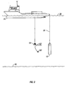
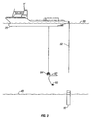
- FIGS. 1-3 are side elevation views of a parking pile being launched from a transport vessel, lowered to the sea bottom, and released and bedded in the sea bottom;
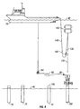
- FIGS. 4-6 are side elevation views of a subsea well tree or any other payload being launched from a vessel, lowered to the sea bottom, and parked on a parking pile;
- FIGS. 7-9 are side elevation views of a parked subsea well tree or any other payload being moved from a parking pile to a distant operating location;
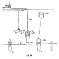
- FIGS. 10-15 are side elevation views of subsea equipment integrally mounted to a framed parking pile being launched, lowered to the sea bottom, and released and bedded together as a unit in the sea bottom;
- FIGS. 16-21 are side elevation views of a parked subsea well tree or any other payload being removed from a framed parking pile and then moved to a distant operating location; and
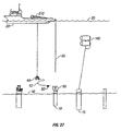
- FIGS. 22-27 are side elevation views of subsea equipment integrally mounted to a parking pile being launched from a transport vehicle with a launching frame, lowered to the sea bottom without the launching frame, and then released and bedded together as a unit in the sea bottom.
- It is to be noted that the drawings illustrate only typical embodiments of the invention and are therefore not to be considered limiting of its scope, for the invention will admit to other equally effective embodiments.
- In general, the present application describes a cost-effective alternative for deploying and installing subsea equipment using a workboat or other vessel of opportunity. The equipment is not supported directly by the vessel, but is instead supported by one or more buoys below the wave zone. The buoys are controlled by a combination of chain, wire rope, and synthetic line linking it to the workboat. As such, the buoy system described herein decouples vessel motion from the payload by supporting the payload from the buoys below the wave zone. Because the buoys are below the wave action and its associated turbulence, there is little energy and hence little tendency for motion. The result is a stable, inexpensive, maneuverable system capable of servicing large subsea payloads in a wide range of water depths.
- Referring now to FIGS. 1-3, there are shown the basic steps in deploying and bedding a
parking pile 10 of the present invention. Theparking pile 10 is launched from the deck of a surface or transport vessel or other vessel ofconvenience 20 such as a workboat, barge, drill ship, or semi-submersible vessel. Theparking pile 10 is lowered from thesurface 30 of the water to thesea bottom 40 by a winch with ahoisting line 50, such as a steel wire, over the stem of thevessel 20. The hoistingline 50 is preferably 3 ½ inch (8.89 cm.) 6-strand wire rope, with a breaking strength around 600 tons (544 tons (metric)) in this particular case, with specific loads being handled (for other loads the diameter and breaking strength could be different). As theparking pile 10 nears thesea bottom 40, it is released from the wire 50 (for example, by an ROV-activated release mechanism), and then partially embeds itself into thesea bottom 40. - Preferably, the
parking pile 10 weighs from about 30 tons to about 60 tons (27.2 - 54.4 tons (metric)), has a diameter from about 8 feet to about 12 feet (2.44 - 3.66 m.), and is from about 20 feet to about 120 feet in length (6.1 - 36.6 m.). When embedded in the sea floor, from about 5 feet to about 10 feet (1.52 - 3.04 m.) in length of the parking pile is above the sea floor mud line. The piles are usually stiffened steel tubular sections (pipes) but could also be of different sections and materials capable of carrying the loads and penetrating the sea floor. For example, it may also have the package (THS or tree) attached to the top of the parking pile, in which case the pile is longer and larger in order to have the correct penetration into the sea floor, as well as provide sufficient clearance of the package above the sea floor on final penetration. Depending upon the need, more than one of these suction piles 10 can be deployed to the sea bottom 40 to form a wet parking system. As might be expected, some engineering modifications to the suction piles are needed to allow for the attachment of the subsea equipment. For example, a different location and orientation for the pumping path and the exit path for the suction pile may be needed. Moreover, a solid plate or perforated plate (or similar device) may be added to the suction pile to arrest penetration into the subsea floor. - If desired, a remotely operated vehicle (ROV) 60, which swims on an umbilical 62 from a
cage 64, can be deployed from thevessel 20 and used to monitor or assist with the launching, lowering, releasing, or embedding of theparking pile 10. TheROV 60 provides visual feedback to the operators, final guidance of the payload, and can operate any latch and release mechanisms. - When one or more parking piles 10 are bedded in the sea bottom 40, a variety of subsea equipment or other payloads, such as a subsea
tubing hanger spool 70 or asubsea well tree 80, may be installed or "parked" on thepiles 10. These loads or packages may be landed on the parking piles separately, or launched attached with the parking piles. A suitable interface between the subsea equipment and the parking pile is provided. For example, the top of the parking pile may have a modified stump profile adapted to whatever subsea package is sent down. A standard tubing hanger spool incorporates upward facing or funnel up tops and downward facing or funnel down bottom interfaces. Its weight in air is approximately 30 short tons (27.2 tons (metric)). The tubing head spool provides a transition between the wellhead housing and the Christmas tree, as well as a transition from the subsequently installed tree production flow-loop and well jumper via a U-loop assembly. The subsea well tree is landed on the tubing head and weighs approximately 40 short tons in air. - By way of example, FIGS. 4-6 illustrate the basic steps in parking a
subsea well tree 80 or any other payload on aparking pile 10. In FIG. 4, thesubsea tree 80 is attached to anoverboarding line 100, such as a steel wire (preferably a 3 ½ inch (8.89 cm.) diameter wire with approximately 600 ton (544 tons (metric)) breaking load). Thetree 80 is lowered into the water with the aid of aboom crane 90. Theboom crane 90 may be located on the deck of thevessel 20 or on another vessel of convenience. Alternatively, a large A-frame can be used to overboard the package into the water off the stem or through a moonpool in the deployment vessel. Thetree 80 is supported in the water by one or more synthetic foam subsurface buoys 110 which are attached to thesubsea tree 80 by apendant line 120. Thependant line 120 must be strong enough to support the subsea payload and its own line weight with a significant safety margin to allow for wear and/or dynamic loads. While many different materials can be selected, thependant line 120 is usually a steel wire or a high strength synthetic fiber rope or a combination of the two joined by 55-ton (49.9 metric tons) shackles. Preferably, the pendant line is 3-inch (7.62 cm.) rope available from Marlow Superline. This rope is known for its relatively light weight (approximately 9 times less than steel), being almost neutrally buoyant, and having a slightly smaller elastic modulus (approximately 3 times smaller). Moreover, an important advantage of synthetic fiber over steel wire is the overall payload reduction including rope, winches, and supporting infrastructure for deployment. - In FIGS. 4-6, the subsurface buoys 110 that are used to initially install the subsea equipment are synthetic foam buoys depth rated from about 3,000 to about 5,000 feet (914-1524 m.). As is known to those skilled in the art, the use of a deep buoyancy design allows for a correspondingly short steel pendant line so that the weight of the pendant is minimized and the total carrying capacity of the buoys is not affected. The
buoys 110 support thewell tree 80, thependant line 120, and part of thechain weight 130, described below. They operate below the wave zone and ideally below the surface current. The actual location of the buoys in the water column is a trade-off between the overall system performance and the cost of buoyancy to resist large hydrostatic pressure. Each of thebuoys 110 is about 13 feet (3.96 m.) tall and 8 feet (2.44 m.) in diameter and weighs about 12,700 lbs (5.7 metric tons) dry. Each buoy provides about 60 kips (27,215 kg) of buoyancy in seawater. Each buoy is preferably surrounded by a metal protective cage, such as a pipe frame, to prevent chaffing from the chain motion. The required buoyancy is the sum of the payload weight, running tool and associated rigging weight, pendant wire weight, submergence allowance, and trim allowance chain weight. - The subsurface buoys 110 are attached to the
vessel 20 by adeployment line 140, such as a steel wire, and a length ofchain 130, which forms a catenary loop between thewire 140 and thebuoys 110. Depending upon the depth involved, the length of thedeployment line 140 is from about 3000 feet to about 4000 feet (914-1219 m), and the length of thechain 130 is from about 1500 feet to about 2000 feet (457-609 m.). Thedeployment line 140 must be strong enough to support the chain weight and its own line weight with a significant safety margin to allow for wear and/or shock loads. Also, one must consider hydrodynamic drag from the buoy in a worst-case scenario where the chain is entangled with the buoy and the system is uncompensated. Most preferably, thedeployment line 140 is 3 ½ inches (8.89 cm.) diameter wire rope with a breaking strength around 600 tons (544 metric tons). As is known to those skilled in the art, the stiffness of the line, which is a function of rope size (diameter), material (steel or synthetic fiber), and type of construction (such as 6 or 8 strand wire and/or spiral strand or plaited construction), may be varied depending upon the operating conditions. Moreover, the recommended practices for deployment lines suggests larger factors of safety ranging from 6 to 8 and even 10 due to the highly dynamic nature of load lifting and the frequent cyclic reeling of the line over sheaves which accumulates fatigue damage as well as significant wear and tear. - The
chain 130 serves many purposes. The chain "belly" allows the workboat orvessel 20 to heave independently of the buoys. As the vessel stem heaves up and down, the neutral point in the chain belly shifts and transfers chain weight to and from the buoy. This load transfer could theoretically cause the buoys to move up and down, defeating the purpose of the present invention. This type of motion, however, can be eliminated by engineering the heave compensated landing system around the resonant periods of each sub-system. When properly designed, the chain load is transferred to and from the buoys too quickly for the buoys/payload to respond. This effectively de-couples the buoys from the vessel. Specific attention must be paid to the environmental conditions. Also, because the chain's weight is supported by both the buoys and the vessel, the buoys will naturally come to equilibrium with the sum of its buoyancy, payload, and partial chain weight. Thus the chain automatically facilitates trim adjustment for small weight inaccuracies. - In addition, the
chain 130 is needed to provide enough weight at the end of thedeployment line 140 to avoid slack line conditions during fully deployed dynamic responses, to avoid "snap loading" during retrieval, and to avoid excessive lateral excursion during high current loads. The size of thechain 130 allows for designer's prerogative. The larger the size, e.g. 3-inch (8.89 cm.) versus 2-inch (5.1 cm.) chain, the shorter the required length. One ormore clump weights 150 can also be used to reduce the total length of chain required. Of course, it is possible to use different size chains in the same system, subject to well-defined package weights and buoyancy. Different chain sizes, however, are significantly more difficult to handle and store on board the surface vessel. - Selecting the chain size and weight requires establishing a balance between optimizing the chain "belly" below the buoys and de-coupling the buoys from the boat. The chain size should facilitate a reasonable belly length, be easily handled on the deck, and be fairly light. Preferably, the chain is 3 ¼-inch (8.26 cm.) chain with a dry weight of about 59-lb/ft (87.7 kg/m) chain and is used in a section of from about 1000 feet to about 2000 feet long (304.5 - 609 m).
- It is preferred that swivels, such as 45-ton (40.8 metric tons) eye-and-eye swivels, be used to compensate for rotation of the wires, lines, and chain. Preferably, swivels are used at each rope or wire connection point to manage twisting, kinking, and entanglement of the ropes. Standard wire rope is not torque-balanced and will twist as load is applied and relaxed. In the case of the present invention, which employs thousands of feet of wire, this can cause twisting and entanglement of the subsea equipment. Torque-balanced wire is available, but is expensive and usually not 100% balanced. Swivels placed into select points allow the wire to react without entangling the system. Ball bearing swivels are preferred because of their low turning friction.
- A winch or draw works 22 near, or deploying over, the stem of the
surface vessel 20 is used to raise or lower thedeployment line 140 and theoverboarding line 100. Various configurations are possible, and depending on the availability and capacity of a stem-mounted A-frame, the lines could run off an A-frame using a double drum winch unit. The system requires a large drum capacity to handle large amounts of wire and chain, and high speed to transit to and from the sea bottom. Anchor handling winches generally meet these requirements. Once submerged, the load is transferred from theoverboarding line 100 to thependant line 120 and buoys 110. AnROV 60 then releases theoverboarding line 100. The operation can be repeated for each component. By way of illustration, in FIG. 5, theoverboarding steel wire 100 is released, such that thesubsea tree 80 is connected to thevessel 20 through thedeployment steel wire 140,chain 130, buoys 110, andpendant rope 120. - The weight of the catenary loop of the
chain 130 is shared between the subsurface buoys 110 and thesurface vessel 20 and the depth of the subsurface buoys is controllable in part through the deployment line by adding significant weight to the catenary loop. For example, one ormore clump weights 150 may be added to thechain 130. Preferably, theclump weights 150 are about 20,000 lbs to 30,000 lbs (9.07 - 13.6 metric tons) each. Clump weights significantly reduce the length of chain required, and associated handling and storage thereof. The clump weights are also used to compensate the weight of the package when it is released and to lift and lower the buoys collaborating with the chain "belly." In FIG. 6, the clump weights move around the "belly" to be carried by thebuoys 110, thereby compensating for the load of thesubsea tree 80 being transferred to theparking pile 10, thereby lowering and engaging thesubsea tree 80 on top of theparking pile 10. AnROV 60 can be used to monitor the lowering of the subsea equipment, park the subsea equipment on thepile 10, and provide means for releasing theoverboarding line 100 or thependant line rope 120 from the equipment or payload. - FIGS. 4-6 also show a subsea tubing hanger spool parked on its
own parking pile 10 and one or more "parked" subsurface steel buoys 160 which are attached or tethered to adifferent parking pile 10 byrope 170. Here, thebuoys 160 are steel buoys depth rated from about 300 to about 500 feet (91.4-152.4 m.), well below the subsurface wave zone. These are 50 kip buoyancy steel cylinders with ellipsoidal heads filled with air. Each of thebuoys 160 is approximately 18 feet tall and 10 feet in diameter and weighs about 12,700 lbs. (5760.6 kg) dry. Each buoy provides about 50 kips (22,679 kg) of buoyancy in seawater. One potential source for these submersible buoys is a steel submersible buoy design. To prevent chaffing from the chain motion, smooth steel buoys are preferred. Instead of being tethered to a parking pile alone, thebuoys 160 may also be tethered to a variety of parked subsea equipment. As is known to those skilled in the art, the use of a near surface buoyancy design allows for a correspondingly very long pendant line. Again, the actual depth of the buoy is a trade-off between system performance and the cost of buoyancy. For instance, a shallow buoyancy case would have a relatively long pendant line that could eventually lead to significant dynamic response. On the other hand, the advantage of the shallow-buoy system would be in the expense of the buoy relative to a deep-water deployment buoy. - Turning now to FIGS. 7-9, there are shown the basic steps in moving a previously parked piece of subsea equipment to a desired operating location, such as a
wellhead 180. The distance from the parking pile to the operating location could be as short as a few feet to several hundred feet, preferably 300 feet (91.4 m). This distance provides sufficient clearance to account for vessel sizes, adjacent mooring lines, environmental loads, and the like, so as to avoid collisions. - Specifically, in FIG. 7, a
subsea tree 80 is parked on aparking pile 10. One or more steel buoys 160, such as a 50 kip (22,679 kg) buoy, are tethered to the parkedtree 80 with apendant line 170, such as dyneema rope. While many different materials can be selected, thependant line 120 is usually a steel wire or a high strength synthetic fiber rope such as dyneema rope or a combination of the two joined by shackles and swivels. Preferably, the pendant line is a combination of 200 feet (60.96 m) of 2¼-inch (5.715 cm) wire rope, 600 feet (182.9) of rope, and 5500 feet (1676.4 m) of rope joined by 55-ton (49.9 metric ton) shackles with 45-ton (40.8 metric ton) eye-and-eye swivels. The pendant line may be terminated near the sea bottom with a 3-inch (7.62 cm) lifting ring from which three 30 feet (9.14 m) sections of 1½ inch (3.86 cm) wire ropes disperse to provide a lifting sling or three "spaced" connection points with the subsea equipment. When it is desired to move thesubsea tree 80 to atubing hanger spool 190 mounted to thewellhead 180, thechain 130,steel wire 140, and clump weights 150 (all described above) are lowered from thevessel 20 and attached to the bottom of the steel buoys 160. As before, the short chain 130 (from about 50 feet to about 400 feet (15.24-121.92 m), preferably 155 feet (47.24 m) of 3¼ inch (8.255 cm) chain is attached to thebuoys 160 and hangs to form a "belly" before rising to thevessel 20. This allows the workboat orvessel 20 to heave independently of thebuoys 160. - In FIG. 8, the
steel wire 140 is then raised or winded up toward thevessel 20. As theclump weights 150 approach the depth of the steel buoys 160, the buoys begin to float toward thesurface 30 of the water, thus lifting thesubsea tree 80 from theparking pile 10. With the assistance of anROV 60, thesubsea tree 80 can then be moved close and steady above thetubing hanger spool 190. While only one ROV is shown in the drawings for monitoring and releasing the payloads, additional ROVs can be used in the present invention to monitor other subsea activities, such as the interaction of thechain 130 and thependant line 170 with thebuoys 160. As such, a combination of working class and observation class ROVs may be used with the present invention. - In FIG. 9, the deployment line or
steel wire 140 is lowered or payed out causing thebuoys 160 to fall to equalize the load. With the assistance of the ROV, thesubsea tree 80 is then engaged or mounted on thetubing hanger spool 190.Chain 130 and clumpweights 150 will move around under the buoys in order to take the load of the tree off the pendant line and buoys 160, allowing the tree to be carried fully by thewellhead 180. TheROV 60 can also be used to release the pendant line ordyneema rope 170 from thetree 80. - Another embodiment of the wet parking system of the present invention is pictured in FIGS. 10-15. Instead of bedding the parking piles and then "parking" the subsea equipment in two steps, the subsea equipment may be integrally mounted to the parking pile (while on the vessel), and then horizontally launched, lowered through the water column, and bedded together as a unit into the sea bottom.
- In this embodiment, the subsea equipment, such as a
subsea tree 80, is protected within ametal frame 200 attached to the upper portion of theparking pile 10. Themetal frame 200 surrounds the subsea equipment and protects its delicate components or interfaces. Theframe 200 is used as hinge structure when overboarding and also serves as protection to sensitive equipment components such as piping, controls, seals, control panels, ROV interfaces, and the body of the equipment itself. As before, the combinedparking pile 10 and subsea welltree 80 or other payload is launched from the deck of atransport vessel 20 and lowered from thesurface 30 of the water to the sea bottom 40 with a hoisting line orsteel wire 50. If desired, mass traps may be added to the hoisting line and lowering line axial properties can be engineered to achieve the desired strength and dynamic response properties. - FIG. 12 shows the
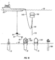
parking pile 10,metal frame 200, andsubsea tree 80 being lowered by the hoistingline 50 and alaunching line 52. As seen in FIG. 13, once the framed pile with package is submerged, a remotely operatedvehicle 60 is used to release the launching line 52 (for example, by an ROV-activated release mechanism). Thepile 10 is then lowered to the sea bottom 40 with only the hoistingline 50. As the framed pile with package reaches the sea bottom 40, theROV 60 releases thehoisting line 50 so that the framed pile with package embeds itself into thesea bottom 40. TheROV 60 can provide visual feedback to the operators and final guidance of the framed pile with package. Of course, the framed pile may also be parked on the sea bottom as described above without carrying any package or subsea equipment in its descent to the sea bottom. - Turning now to FIGS. 16-21, there are shown the basic steps in moving a previously parked piece of
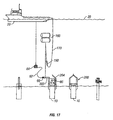
subsea equipment 80, brought to the sea bottom 40 within aframe 200 on thepile 10, to a desired operating location, such as awellhead 180. In this embodiment of the wet parking system, before moving the parked subsea equipment, theframe 200 must be unhinged or otherwise removed to gain access to the protected subsea equipment. - FIG. 16 shows a
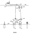
tree 80 parked within aframe 200 on a beddedparking pile 10. In FIG. 17 anROV 60 operates a tool that is attached to thependant line 170 to remove or open one of the hingeddoors 202 of thepile frame 200. In FIG. 18, theother door 204 is similarly opened. Withdoors tree 80. - In FIG. 19, one or more steel buoys 160 are tethered to the parked
tree 80 with apendant line 170, such as rope. When it is desired to move thesubsea tree 80 to atubing hanger spool 190 mounted to thewellhead 180, thesteel wire 140 is raised or winded up toward thevessel 20. As theclump weights 150 are carried bysteel wire 140 and no longer bybuoys 160, the buoys begin to float toward thesurface 30 of the water, thus lifting thesubsea tree 80 from theparking pile 10. - As seen in FIG. 20, with the assistance of an
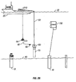
ROV 60, thesubsea tree 80 can be transported to the location of interest (such as a wellhead 180) and then be moved close and steady above thetubing hanger spool 190. If the distance between the pile where the payload is removed and the operating location of interest is far, the vessel itself may be used to transport the payload to the location of interest. While only one ROV is shown in the drawings for transporting the payloads, additional ROVs can be used in the present invention to transport the payloads and to monitor other subsea activities, such as the interaction of thechain 130 and thependant line 170 with thebuoys 160. - In FIG. 21, the deployment line or
steel wire 140 is lowered or payed out causing thebuoys 160 to fall to equalize the load. With the assistance of the ROV, thesubsea tree 80 is then engaged or mounted on thetubing hanger spool 190. TheROV 60 can also be used to release the pendant line ordyneema rope 170 from thetree 80. - In yet another embodiment of the wet parking system of the present invention, shown in FIGS. 22-27, the subsea equipment is again integrally mounted to the parking pile, but without the protective metal frame. In this embodiment, a launching device or
frame 210 is used to horizontally launch the combinedparking pile 10 andtree 80. Thelaunching frame 210 physically distances thetree 80 from thevessel 20, such that when thepile 10 andtree 80 are transported on and launched from thevessel 20, thetree 80 does not touch, crash into, or otherwise bang on thevessel 20. - FIG. 22 shows the
parking pile 10 andsubsea package 80 supported by the launchingframe 210 on the deck of thevessel 20. The launching frame is a truss like steel structure forming a wedge shaped frame. Other lightweight materials are also possible such as aluminum or composites if necessary and/or cost effective. Whatever configuration, the launching frame should support the load, take bending moments, and keep the equipment a safe distance from the vessel. FIGS. 23 and 24 show the launching of all three apparatuses, theparking pile 10,subsea package 80, and launchingframe 210, from the stem of thetransport vessel 20. The launching is facilitated by ahoisting line 50 attached to the top of thesubsea tree 80 and alaunching line 52 attached to thelaunching frame 210. In FIG. 25, the launchingframe 210 is separated from theparking pile 10 andsubsea package 80. In FIG. 26, the launchingframe 210 is retrieved and returned to the deck of thetransport vessel 20. Theparking pile 10 and its mountedsubsea equipment 80 are lowered to the sea bottom 40 with the hoistingline 50. If desired, mass traps may be added to the hoisting line and lowering line axial properties can be engineered to achieve the desired strength and dynamic response properties. In FIG. 27, the parking pile with the subsea equipment package is released and bedded in thesea bottom 40. Instead of being a separate and reusable device, in other embodiments, the launching frame could be integrally formed with or connected to the suction pile and bedded. - Although the present invention and its advantages have been described in detail, it should be understood that various changes, substitutions, and alterations could be made herein without departing from the spirit and scope of the invention as defined by the appended claims.
Claims (10)
- An apparatus for deploying and installing subsea equipment from a surface vessel (20) to the sea floor (40), said apparatus comprising:a subsurface buoy (110,160);a pendant line (170) connecting the subsea equipment (80) to the subsurface buoy (110,160);a deployment line (140) having a catenary loop below the subsurface buoy (110,160), the deployment line (140) being supported by the subsurface buoy (110,160) on one end and connected to the surface vessel (20) on the other end, the subsea equipment (80), subsurface buoy (110,160), pendant line (170), and deployment line (140) cooperating to establish a natural frequency for the suspended subsea equipment (80) which is materially different from the average wave frequency acting on the surface vessel (20); anda subsea structure partially embedded in the sea floor (40), on which the subsea equipment (80) may be parked, characterised in that the subsea structure is a parking pipe (10), which is configured to embed itself into the sea floor (40).
- The apparatus of claim 1 wherein the subsurface buoy (110,160) is formed from synthetic foam.
- A method for positioning a subsea work package (80) at a desired deepwater offshore location comprising:launching the subsea work package (80) from a transport vessel (20);lowering the subsea work package (80) to the sea floor (40) with a combination of wire (170), chain (130), clump weights (150), subsurface buoys (110,160), and synthetic line (120); andarranging the subsea work package (80) on a subsea structure, characterised in that the subsea structure is a parking pipe (10), which is
launched from a transport vessel (20);
lowered to the sea floor (40) with a hoisting line (50); and
released from the hoisting line (50) such that the pipe (10) partially embeds itself into the sea floor (40). - The method of claim 3, wherein the parking pipe (10) is partially embedded into the sea floor (40) and subsequently the subsea work package (80) is lowered to the sea floor (40) and parked on the partially embedded parking pipe (10).
- The method of claim 3, wherein the subsea work package (80) is mounted on the parking pipe (10) before launching the parking pipe (10) and subsea package (80) from the transport vessel (20) and said pipe (10) and package (80) are lowered together to the sea floor (10), and wherein the pipe (10) and package (80) are released from the hoisting line (50) such that the pipe (10) partially embeds itself into the sea floor (40).
- The method of claim 5, further comprising:providing a protective frame (200) to surround the mounted subsea work package (80).
- The method of claim 5, further comprising:providing a launching frame for launching the parking pipe (10) and subsea package (80) from the transport vessel (20).
- The method of claim 5, further comprising:moving the parked subsea work package (80) to an operating location.
- The method of claim 6, further comprising:removing the protective frame (200) surrounding the parked subsea work package (80); and moving the parked subsea work package to an operating location.
- The method of claim 3, wherein the parking pipe (10) is a suction pile which embeds itself into the sea floor (40).
Applications Claiming Priority (3)
| Application Number | Priority Date | Filing Date | Title |
|---|---|---|---|
| US10/156,713 US6752100B2 (en) | 2002-05-28 | 2002-05-28 | Apparatuses and methods of deploying and installing subsea equipment |
| US156713 | 2002-05-28 | ||
| PCT/US2003/016730 WO2003100207A1 (en) | 2002-05-28 | 2003-05-28 | Apparatuses and methods of deploying and installing subsea equipment |
Publications (2)
| Publication Number | Publication Date |
|---|---|
| EP1509672A1 EP1509672A1 (en) | 2005-03-02 |
| EP1509672B1 true EP1509672B1 (en) | 2006-03-08 |
Family
ID=29582322
Family Applications (1)
| Application Number | Title | Priority Date | Filing Date |
|---|---|---|---|
| EP03734221A Expired - Lifetime EP1509672B1 (en) | 2002-05-28 | 2003-05-28 | Apparatuses and methods of deploying and installing subsea equipment |
Country Status (8)
| Country | Link |
|---|---|
| US (1) | US6752100B2 (en) |
| EP (1) | EP1509672B1 (en) |
| AU (1) | AU2003239913A1 (en) |
| BR (1) | BR0311168B1 (en) |
| CA (1) | CA2485386A1 (en) |
| MY (1) | MY136607A (en) |
| NO (1) | NO331066B1 (en) |
| WO (1) | WO2003100207A1 (en) |
Families Citing this family (31)
| Publication number | Priority date | Publication date | Assignee | Title |
|---|---|---|---|---|
| WO2003062042A1 (en) * | 2002-01-24 | 2003-07-31 | Stolt Offshore Limited | Method and apparatus for deploying articles in deep waters |
| WO2004009434A1 (en) * | 2002-07-23 | 2004-01-29 | Philip Head | Seabed installation apparatus |
| GB2439902B (en) * | 2005-05-27 | 2008-12-31 | Shell Int Research | Method for installing oilfield equipment at the water bottom |
| GB0615884D0 (en) * | 2006-08-10 | 2006-09-20 | Subsea 7 Ltd | Method and frame |
| BRPI0702808A2 (en) * | 2007-06-22 | 2009-08-04 | Petroleo Brasileiro Sa | subsea module installation and exchange system and subsea module installation and exchange methods |
| WO2010019675A2 (en) * | 2008-08-13 | 2010-02-18 | Schlumberger Technology Corporation | Umbilical management system and method for subsea well intervention |
| US8316947B2 (en) * | 2008-08-14 | 2012-11-27 | Schlumberger Technology Corporation | System and method for deployment of a subsea well intervention system |
| AU2009283041B2 (en) * | 2008-08-21 | 2012-12-20 | Shell Internationale Research Maatschappij B.V. | Subsea structure installation or removal |
| GB2464714B (en) * | 2008-10-24 | 2010-09-08 | Subsea Deployment Systems Ltd | Method and apparatus for subsea installations |
| EP2196622A1 (en) * | 2008-12-12 | 2010-06-16 | Welltec A/S | Subsea well intervention module |
| MY168604A (en) * | 2010-02-12 | 2018-11-14 | Shell Int Research | Rigless intervention |
| US8657531B2 (en) * | 2010-03-16 | 2014-02-25 | Technip France | Installation method of flexible pipe with subsea connector, utilizing a pull down system |
| WO2011150363A1 (en) * | 2010-05-28 | 2011-12-01 | Weatherford/Lamb, Inc. | Deepwater completion installation and intervention system |
| US20120037378A1 (en) * | 2010-08-10 | 2012-02-16 | Vetco Gray Inc. | Tree protection system |
| US8425154B1 (en) * | 2010-08-30 | 2013-04-23 | Trendsetter Engineering, Inc. | System and method for repairing and extended length of a subsea pipeline |
| US8657012B2 (en) * | 2010-11-01 | 2014-02-25 | Vetco Gray Inc. | Efficient open water riser deployment |
| US9316066B2 (en) * | 2011-09-16 | 2016-04-19 | Woodside Energy Technologies Pty Ltd. | Redeployable subsea manifold-riser system |
| US9033049B2 (en) | 2011-11-10 | 2015-05-19 | Johnnie E. Kotrla | Blowout preventer shut-in assembly of last resort |
| US9254894B2 (en) | 2013-02-19 | 2016-02-09 | Conocophillips Company | Flotable subsea platform (FSP) |
| US9321514B2 (en) | 2013-04-25 | 2016-04-26 | Cgg Services Sa | Methods and underwater bases for using autonomous underwater vehicle for marine seismic surveys |
| US9359852B2 (en) | 2013-06-24 | 2016-06-07 | Trendsetter Vulcan Offshore, Inc. | Systems and methods for tethering subsea blowout preventers to enhance the strength and fatigue resistance of subsea wellheads and primary conductors |
| GB2535717B (en) * | 2015-02-24 | 2020-11-25 | Equinor Energy As | Pipeline method and apparatus |
| GB2535716B (en) | 2015-02-24 | 2020-11-25 | Equinor Energy As | Direct tie-in of pipelines by added curvature |
| WO2017079627A1 (en) * | 2015-11-06 | 2017-05-11 | Vetco Gray Inc. | Installation assembly for a subsea wellhead |
| GB2564665B (en) * | 2017-07-18 | 2020-06-03 | Equinor Energy As | Subsea installation method |
| NO20171355A1 (en) | 2017-08-15 | 2019-02-11 | Protan As | Device for lice skirts |
| GB2576333C (en) | 2018-08-14 | 2024-05-08 | Subsea 7 Do Brasil Servicos Ltda | Handling loads in subsea operations |
| EP3854746B1 (en) * | 2020-01-22 | 2024-12-18 | Grant Prideco, Inc. | Hoisting system and method for hoisting a vertically-suspended object |
| EP4226013B1 (en) * | 2020-10-05 | 2024-11-27 | ConocoPhillips Company | Subsea equipment installation |
| CN112606976A (en) * | 2020-12-22 | 2021-04-06 | 国家海洋技术中心 | Submersible wave glider |
| WO2022169367A1 (en) * | 2021-02-08 | 2022-08-11 | National Oilwell Varco Norway As | Apparatus, system and methods for moving a load between a floating vessel and a submerged position |
Family Cites Families (9)
| Publication number | Priority date | Publication date | Assignee | Title |
|---|---|---|---|---|
| US4448568A (en) * | 1982-06-22 | 1984-05-15 | Mobil Oil Corporation | Marine surface facility work station for subsea equipment handling |
| GB2132670A (en) * | 1982-12-21 | 1984-07-11 | Sedco Inc | Installation and levelling of subsea templates |
| US4702320A (en) * | 1986-07-31 | 1987-10-27 | Otis Engineering Corporation | Method and system for attaching and removing equipment from a wellhead |
| US4797035A (en) * | 1987-06-05 | 1989-01-10 | Conoco Inc. | Method of installing a template on the seafloor |
| US5190107A (en) * | 1991-04-23 | 1993-03-02 | Shell Oil Company | Heave compensated support system for positioning subsea work packages |
| US5480521A (en) * | 1994-12-16 | 1996-01-02 | Shell Oil Company | Tendon foundation guide cone assembly and anode |
| GB2315083A (en) * | 1996-07-11 | 1998-01-21 | Philip Head | Accessing sub sea oil well |
| US6352114B1 (en) * | 1998-12-11 | 2002-03-05 | Ocean Drilling Technology, L.L.C. | Deep ocean riser positioning system and method of running casing |
| US6250395B1 (en) * | 1999-11-05 | 2001-06-26 | Carlos A. Torres | Apparatus system and method for installing and retrieving pipe in a well |
-
2002
- 2002-05-28 US US10/156,713 patent/US6752100B2/en not_active Expired - Lifetime
-
2003
- 2003-05-26 MY MYPI20031943A patent/MY136607A/en unknown
- 2003-05-28 EP EP03734221A patent/EP1509672B1/en not_active Expired - Lifetime
- 2003-05-28 CA CA002485386A patent/CA2485386A1/en not_active Abandoned
- 2003-05-28 WO PCT/US2003/016730 patent/WO2003100207A1/en not_active Ceased
- 2003-05-28 BR BRPI0311168-7A patent/BR0311168B1/en not_active IP Right Cessation
- 2003-05-28 AU AU2003239913A patent/AU2003239913A1/en not_active Abandoned
-
2004
- 2004-12-27 NO NO20045662A patent/NO331066B1/en not_active IP Right Cessation
Also Published As
| Publication number | Publication date |
|---|---|
| US20030221602A1 (en) | 2003-12-04 |
| CA2485386A1 (en) | 2003-12-04 |
| AU2003239913A1 (en) | 2003-12-12 |
| US6752100B2 (en) | 2004-06-22 |
| MY136607A (en) | 2008-10-31 |
| NO20045662L (en) | 2004-12-27 |
| NO331066B1 (en) | 2011-09-26 |
| EP1509672A1 (en) | 2005-03-02 |
| BR0311168A (en) | 2005-03-15 |
| WO2003100207A1 (en) | 2003-12-04 |
| BR0311168B1 (en) | 2014-04-15 |
Similar Documents
| Publication | Publication Date | Title |
|---|---|---|
| US6752100B2 (en) | Apparatuses and methods of deploying and installing subsea equipment | |
| US5190107A (en) | Heave compensated support system for positioning subsea work packages | |
| CN102132001B (en) | Installation or removal of subsea structures | |
| CN102630211B (en) | lifting equipment | |
| JP7025433B2 (en) | Deep sea hoisting system and method | |
| US7600570B2 (en) | Drilling rig placed on the sea bed and equipped for drilling of oil and gas wells | |
| EP1984237B1 (en) | Deep water installation vessel | |
| US4537533A (en) | Installation and levelling of subsea templates | |
| CN103328756B (en) | Method, system and apparatus for deployment of umbilicals in subsea well operations | |
| EP2326552B1 (en) | Method of locating a subsea structure for deployment | |
| US11377913B2 (en) | Offshore drilling rig comprising an anti-recoil system | |
| US20080251258A1 (en) | Tubing Support Assembly, Vessel And Method Of Deploying Tubing | |
| CN102753759B (en) | Method for lifting an underwater structure and method for installing an underwater structure | |
| CN104024561A (en) | Method and system for wireline intervention in a subsea well from a floating vessel | |
| Nelson et al. | Heave Compensated landing system-A novel tool for subsea intervention | |
| Pollack et al. | Installation of deep water sub-sea equipment | |
| OA19498A (en) | Offshore drilling rig comprising an antirecoil system |
Legal Events
| Date | Code | Title | Description |
|---|---|---|---|
| PUAI | Public reference made under article 153(3) epc to a published international application that has entered the european phase |
Free format text: ORIGINAL CODE: 0009012 |
|
| 17P | Request for examination filed |
Effective date: 20041022 |
|
| AK | Designated contracting states |
Kind code of ref document: A1 Designated state(s): AT BE BG CH CY CZ DE DK EE ES FI FR GB GR HU IE IT LI LU MC NL PT RO SE SI SK TR |
|
| AX | Request for extension of the european patent |
Extension state: AL LT LV MK |
|
| 17Q | First examination report despatched |
Effective date: 20040330 |
|
| GRAP | Despatch of communication of intention to grant a patent |
Free format text: ORIGINAL CODE: EPIDOSNIGR1 |
|
| DAX | Request for extension of the european patent (deleted) | ||
| RBV | Designated contracting states (corrected) |
Designated state(s): GB NL |
|
| REG | Reference to a national code |
Ref country code: DE Ref legal event code: 8566 |
|
| GRAS | Grant fee paid |
Free format text: ORIGINAL CODE: EPIDOSNIGR3 |
|
| GRAA | (expected) grant |
Free format text: ORIGINAL CODE: 0009210 |
|
| AK | Designated contracting states |
Kind code of ref document: B1 Designated state(s): GB NL |
|
| REG | Reference to a national code |
Ref country code: GB Ref legal event code: FG4D |
|
| PLBE | No opposition filed within time limit |
Free format text: ORIGINAL CODE: 0009261 |
|
| STAA | Information on the status of an ep patent application or granted ep patent |
Free format text: STATUS: NO OPPOSITION FILED WITHIN TIME LIMIT |
|
| 26N | No opposition filed |
Effective date: 20061211 |
|
| PGFP | Annual fee paid to national office [announced via postgrant information from national office to epo] |
Ref country code: NL Payment date: 20080526 Year of fee payment: 6 |
|
| NLV4 | Nl: lapsed or anulled due to non-payment of the annual fee |
Effective date: 20091201 |
|
| PG25 | Lapsed in a contracting state [announced via postgrant information from national office to epo] |
Ref country code: NL Free format text: LAPSE BECAUSE OF NON-PAYMENT OF DUE FEES Effective date: 20091201 |
|
| PGFP | Annual fee paid to national office [announced via postgrant information from national office to epo] |
Ref country code: GB Payment date: 20190522 Year of fee payment: 17 |
|
| GBPC | Gb: european patent ceased through non-payment of renewal fee |
Effective date: 20200528 |
|
| PG25 | Lapsed in a contracting state [announced via postgrant information from national office to epo] |
Ref country code: GB Free format text: LAPSE BECAUSE OF NON-PAYMENT OF DUE FEES Effective date: 20200528 |