EP1508944A1 - Electrical apparatus with cover for retractably housing an electrical cable connected thereto - Google Patents
Electrical apparatus with cover for retractably housing an electrical cable connected thereto Download PDFInfo
- Publication number
- EP1508944A1 EP1508944A1 EP04103055A EP04103055A EP1508944A1 EP 1508944 A1 EP1508944 A1 EP 1508944A1 EP 04103055 A EP04103055 A EP 04103055A EP 04103055 A EP04103055 A EP 04103055A EP 1508944 A1 EP1508944 A1 EP 1508944A1
- Authority
- EP
- European Patent Office
- Prior art keywords
- electrical
- cover
- housing
- electrical cable
- transformer
- Prior art date
- Legal status (The legal status is an assumption and is not a legal conclusion. Google has not performed a legal analysis and makes no representation as to the accuracy of the status listed.)
- Granted
Links
- 230000002093 peripheral effect Effects 0.000 claims description 20
- 230000008878 coupling Effects 0.000 claims description 11
- 238000010168 coupling process Methods 0.000 claims description 11
- 238000005859 coupling reaction Methods 0.000 claims description 11
- 238000000034 method Methods 0.000 claims description 9
- 230000014759 maintenance of location Effects 0.000 claims description 8
- 238000004804 winding Methods 0.000 claims description 5
- 230000007246 mechanism Effects 0.000 description 5
- 230000006870 function Effects 0.000 description 3
- 238000003780 insertion Methods 0.000 description 2
- 230000037431 insertion Effects 0.000 description 2
- 230000004075 alteration Effects 0.000 description 1
- 235000012489 doughnuts Nutrition 0.000 description 1
- 230000010354 integration Effects 0.000 description 1
- 238000012986 modification Methods 0.000 description 1
- 230000004048 modification Effects 0.000 description 1
- 238000000926 separation method Methods 0.000 description 1
Images


Classifications
-
- H—ELECTRICITY
- H01—ELECTRIC ELEMENTS
- H01R—ELECTRICALLY-CONDUCTIVE CONNECTIONS; STRUCTURAL ASSOCIATIONS OF A PLURALITY OF MUTUALLY-INSULATED ELECTRICAL CONNECTING ELEMENTS; COUPLING DEVICES; CURRENT COLLECTORS
- H01R13/00—Details of coupling devices of the kinds covered by groups H01R12/70 or H01R24/00 - H01R33/00
- H01R13/66—Structural association with built-in electrical component
- H01R13/6608—Structural association with built-in electrical component with built-in single component
- H01R13/6633—Structural association with built-in electrical component with built-in single component with inductive component, e.g. transformer
-
- H—ELECTRICITY
- H01—ELECTRIC ELEMENTS
- H01R—ELECTRICALLY-CONDUCTIVE CONNECTIONS; STRUCTURAL ASSOCIATIONS OF A PLURALITY OF MUTUALLY-INSULATED ELECTRICAL CONNECTING ELEMENTS; COUPLING DEVICES; CURRENT COLLECTORS
- H01R13/00—Details of coupling devices of the kinds covered by groups H01R12/70 or H01R24/00 - H01R33/00
- H01R13/66—Structural association with built-in electrical component
- H01R13/665—Structural association with built-in electrical component with built-in electronic circuit
- H01R13/6658—Structural association with built-in electrical component with built-in electronic circuit on printed circuit board
-
- H—ELECTRICITY
- H01—ELECTRIC ELEMENTS
- H01R—ELECTRICALLY-CONDUCTIVE CONNECTIONS; STRUCTURAL ASSOCIATIONS OF A PLURALITY OF MUTUALLY-INSULATED ELECTRICAL CONNECTING ELEMENTS; COUPLING DEVICES; CURRENT COLLECTORS
- H01R13/00—Details of coupling devices of the kinds covered by groups H01R12/70 or H01R24/00 - H01R33/00
- H01R13/72—Means for accommodating flexible lead within the holder
-
- Y—GENERAL TAGGING OF NEW TECHNOLOGICAL DEVELOPMENTS; GENERAL TAGGING OF CROSS-SECTIONAL TECHNOLOGIES SPANNING OVER SEVERAL SECTIONS OF THE IPC; TECHNICAL SUBJECTS COVERED BY FORMER USPC CROSS-REFERENCE ART COLLECTIONS [XRACs] AND DIGESTS
- Y10—TECHNICAL SUBJECTS COVERED BY FORMER USPC
- Y10S—TECHNICAL SUBJECTS COVERED BY FORMER USPC CROSS-REFERENCE ART COLLECTIONS [XRACs] AND DIGESTS
- Y10S439/00—Electrical connectors
- Y10S439/956—Electrical connectors with means to allow selection of diverse voltage or polarity
Definitions
- the present invention relates generally to electrical apparatus of the type having a transformer in a housing coupled to a source of commercial AC power and an electrical cable delivering power to an electrical device with which the apparatus is used.
- the invention deals more specifically with a cover integrally carried on the transformer housing surface for manual retraction and housing of the electrical cable.
- AC adapters to provide power to portable electronic devices such as laptop computers, mobile telephones, and other such portable electronic devices and for charging batteries powering such devices.
- These AC adapters may typically have a transformer carried in the housing.
- An electrical plug compatible with the electrical service of a given country is provided for connection to a commercial AC electrical output to provide input power to the adapter.
- An electrical cable generally having a suitable power plug is also provided for delivering power to the electronic device with which the adapter is used.
- the AC adapter may be of different operational modes and have means to function for example, as a switch mode power supply, voltage regulator, AC to DC converter or in other operational electrical circuit configuration means necessary to provide the desired power to the electronic device with which the adapter is used.
- the electrical plug may be integral with the housing to provide a "wall mounted" unit wherein the adapter is plugged directly into the AC outlet without an intervening cord.
- the electrical cable coupling the AC adapter to the electronic device with which the adapter is used is of an indeterminate length sufficient to reach from the commercial AC outlet to the location of the electronic device. In some instances, the electrical cable may be upwards of ten (10) feet.
- a further disadvantage is the electrical cable may become twisted, tangled or knotted when the AC adapter is in use because the full length of the electrical cable may not be required between the AC outlet and the electronic device.
- Cable organizing devices have been proposed for the manual retraction and storage of excess cable length. These devices are typically accessory devices and not part of the AC adapter consequently subject to detachment from the cable and separation from the adapter. Further, such organizers take up additional storage room when the adapter is not in use.
- an electrical apparatus of the type having a transformer carried in a housing and an electrical cable for coupling the transformer output to an electrical device with which the apparatus is used is presented.
- the electrical apparatus is characterized by a cover located on an outer surface of the transformer housing and an interior cavity defined between the inner surface of the cover and the transformer housing outer surface.
- the interior cavity retractably houses the electrical cable within the interior cavity when the electrical apparatus is not in use and when in use, a desired length of the electrical is withdrawn from the interior cavity for connection to the electrical device.
- the cover is made of a resilient deformable material of a suitable type having a shape retention memory wherein the cover is flipped up away from the transformer housing outer surface so that the inner surface of the cover faces outward and a portion of the inner surface of the cover juxtapositioned the transformer housing outer surface defines a tower around which the electrical cable is manually retracted and wound.
- the cover is flipped down toward the transformer housing outer surface for retaining the retracted electrical cable in the interior cavity defined between the inner surface of the cover and the transformer housing outer surface.
- the cover may be flipped up to manually pay off a desired length of the electrical cable.
- a closeable opening is defined along and between the peripheral lip of the cover and the transformer housing outer surface through which closeable opening the electrical cable is manually retracted into the interior cavity and wound around a tower defined within the interior cavity. Additionally, the electrical cable passes through the closeable opening when manually uncoiled from the tower to pay off a desired length of the electrical cable.
- the electrical apparatus has an electrical plug integral with the housing for coupling a source of commercial electrical power to the transformer input.
- the electrical apparatus is a charger.
- the electrical apparatus is a charger and the electrical device is a mobile phone.
- the electrical apparatus is a switched mode power converter and said electrical device is a mobile phone.
- an electrical apparatus in another aspect of the invention, includes a housing for carrying a transformer that has an input and output.
- An electrical plug integral with the housing is provided for coupling an AC commercial voltage outlet to the transformer input.
- An electrical cable has one end coupled to the transformer output and an opposite end terminated in a suitable power plug for coupling the transformer output to a desired electronic device.
- a cover made of a resilient deformable material has shape retention memory characteristics and is located integral with and on an outer surface of the housing.
- An interior cavity is defined between the inner surface of the cover and the outer surface of the housing.
- the interior cavity is further defined by a continuous wall having an inner peripheral wall portion and an outer peripheral wall portion spaced from the inner peripheral wall portion.
- the inner peripheral wall portion juxtapositioned the housing outer surface defines a tower around which the electrical cable is manually retracted and wound for storage within the interior cavity.
- a method for retractably housing the electrical cable in an electrical apparatus of the type having a transformer carried in a housing for coupling the transformer output to an electrical device with which the electrical device is used includes the steps of: providing a cover; locating the cover on an outer surface of the transformer housing to define an interior cavity between the inner surface of the cover and the transformer housing outer surface; retractably housing the electrical cable within the interior cavity when the electrical apparatus is not in use, and withdrawing a desired length of the electrical cable from the interior cavity for connection to the electrical device.
- the method further includes the steps of: providing a cover made of a resilient deformable material having a shape retention memory; flipping the cover up away from the transformer housing outer surface whereby the inner surface of the cover faces outward and a portion of the outwardly facing inner surface juxtaposed the transformer housing outer surface defines a tower; manually retracting and winding the electrical cable around the tower, and flipping the cover down toward the transformer housing outer surface to retain the retracted electrical cable.
- the method further includes the steps of: providing a closeable opening along and between the peripheral lip of the cover and the transformer housing outer surface, and manually retracting the electrical cable into the interior cavity through the closeable opening.
- the method further includes the step of winding the electrical cable around a tower defined within the interior cavity.
- electrical apparatus generally designated 10 of the type having a transformer generally designated 12 carried in a housing 14 includes an electrical cable 16 having one end 18 coupled to the transformer output and an opposite end 20 having a suitable configured power plug 22 for connection to an electrical device with which the electrical apparatus 10 is used.
- the electrical apparatus 10 includes an electrical plug 24 having suitably configured and arranged prongs 26 arranged for insertion and electrical connection with a commercial AC power outlet (not shown).
- the electrical plug 24 is configured and arranged to be integral with the housing 14 such that the housing 14 and electrical plug 24 form and define a unitary assembly 28.
- the electrical plug 24 may alternately be located and positioned at any desired location on the housing suitable to permit insertion of the prongs 26 into a power outlet. It will also be noted by those skilled in the art that there are many different prong arrangements and configurations to accommodate the electrical power distribution schemes as used in various different countries and accordingly all such prong and plug arrangements are contemplated by the present invention.
- a cover generally designated 30 is arranged and located on an outer surface 32 of the housing 14.
- the cover 30 has an outer surface 34 and an inner surface 36.
- the cover 30 has an outer peripheral edge 40 and a inner peripheral edge 42 in a spaced relation with the outer peripheral edge 40 defining an open end of the cover 30 therebetween generally designated 43 and terminating substantially at the outer surface 32 of the housing 14.
- the cover 30 may be of any desired geometric shape and contour having a continuous wall portion with an interior wall 44 extending to an outer wall 46 and defining an interior cavity 38 between the cover inner surface 36 and the outer surface 32 of the housing 14.
- the cover inner surface 36 along the interior wall 44 defines a tower-like structure generally designated 48 around which the electrical cable 16 is manually retracted and wound such that the retracted electrical cable 16 is stored within the interior cavity 38 as best illustrated in Fig. 2.
- the cover 30 is made of a suitable resilient deformable material having shape retention memory characteristics such that a closeable opening generally designated 50 is formed between the lip of the outer peripheral edge 40 of the cover following along the path defined between the outer peripheral edge 40 and the housing 14.
- the cover material may be of any material well known to those skilled in the art or future developed material to carry out the intended function.
- the electrical cable 16 passes through and is manually guided along the closeable opening 50 and wound on to the tower 48 to retract the electrical cable.
- the electrical cable 16 may likewise be manually withdrawn through the closeable opening 50 to uncoil the cable from the tower 48 to pay off a desired length of the electrical cable.
- the cover 30 may alternately be flipped up as illustrated in FIGS. 3 and 4 such that the outer peripheral edge 40 is not in contact with the surface 32 of the housing 14 to reveal the tower 48 around which the electrical cable 16 may be manually retracted and wound after which the cover 30 is flipped down such that the outer peripheral edge 40 is in contact with the outer surface 32 of the housing 14 thereby forming and defining the interior cavity 38 for retractably housing the electrical cable when the electrical apparatus is not in use.
- the cover 30 may be flipped up so that the electrical cable 16 may be manually uncoiled from the tower 48 to pay off the desired length of the electrical cable.
- the cover 30 is then flipped down such that the peripheral edge 40 is in contact with the outer surface 32 of the housing 14 whereby the cover 30 returns to its original shape due to the memory retention characteristic of the material forming the cover 30.
- the electrical apparatus 10 may include a transformer 12 as illustrated in the dash-line box in Fig. 2 or may further include suitable electronic circuitry defining means to function as a charger or a switched-mode power converter or other desired operational electrical circuit means to provide the required power to an electronic device with which the electrical apparatus 10 is used.
- the electronic device may be a mobile phone as shown in phantom in Fig. 4 and generally designated 52.
- cross-sectional geometric shape of the cover 30 may be that other than shown in the figures and for example may be doughnut shaped, trapezoidal shaped, rhomboid shaped, or other desired suitable shape and configuration to accommodate the housing with which the cover is utilized.
Landscapes
- Engineering & Computer Science (AREA)
- Microelectronics & Electronic Packaging (AREA)
- Power Engineering (AREA)
- Connector Housings Or Holding Contact Members (AREA)
- Details Of Indoor Wiring (AREA)
Abstract
Description
- The present invention relates generally to electrical apparatus of the type having a transformer in a housing coupled to a source of commercial AC power and an electrical cable delivering power to an electrical device with which the apparatus is used. The invention deals more specifically with a cover integrally carried on the transformer housing surface for manual retraction and housing of the electrical cable.
- It is known to use AC adapters to provide power to portable electronic devices such as laptop computers, mobile telephones, and other such portable electronic devices and for charging batteries powering such devices. These AC adapters may typically have a transformer carried in the housing. An electrical plug compatible with the electrical service of a given country is provided for connection to a commercial AC electrical output to provide input power to the adapter. An electrical cable generally having a suitable power plug is also provided for delivering power to the electronic device with which the adapter is used. The AC adapter may be of different operational modes and have means to function for example, as a switch mode power supply, voltage regulator, AC to DC converter or in other operational electrical circuit configuration means necessary to provide the desired power to the electronic device with which the adapter is used. The electrical plug may be integral with the housing to provide a "wall mounted" unit wherein the adapter is plugged directly into the AC outlet without an intervening cord. The electrical cable coupling the AC adapter to the electronic device with which the adapter is used is of an indeterminate length sufficient to reach from the commercial AC outlet to the location of the electronic device. In some instances, the electrical cable may be upwards of ten (10) feet.
- One disadvantage associated with such AC adapters is there is no convenient method or means for housing the electrical cable when the AC adapter is not in use and the electrical cable becomes twisted, tangled and knotted.
- A further disadvantage is the electrical cable may become twisted, tangled or knotted when the AC adapter is in use because the full length of the electrical cable may not be required between the AC outlet and the electronic device.
- Various mechanical mechanisms have been proposed for use in electronic devices to automatically retract cords such as earphone/microphone chords, data/telephone line chords and the like. Typically such mechanisms are used for retracting relatively small flexible cables such as used for earphone/microphone and data connections and are not suitable for heavier electrical cables such as power cables used to carry power from an AC adapter to an electronic device. Additionally, such mechanical devices and winding mechanisms are complex, and costly. Further, integration of such retraction mechanisms add to the cost and weight of the electronic apparatus utilizing such mechanisms.
- Cable organizing devices have been proposed for the manual retraction and storage of excess cable length. These devices are typically accessory devices and not part of the AC adapter consequently subject to detachment from the cable and separation from the adapter. Further, such organizers take up additional storage room when the adapter is not in use.
- It would be desirable therefore to provide an inexpensive and convenient means for manual retraction and storage of the electrical cable of an AC adapter.
- Accordingly, it is an object of the present invention to provide a convenient and inexpensive means for manual retraction of the electrical cable of an AC adapter for housing the electrical cable when the AC adapter is not in use and such that when in use, a desired length of the electrical cable is withdrawn for connection to the electrical device with which the AC adapter is used.
- In accordance with a first aspect of the invention, an electrical apparatus of the type having a transformer carried in a housing and an electrical cable for coupling the transformer output to an electrical device with which the apparatus is used is presented. The electrical apparatus is characterized by a cover located on an outer surface of the transformer housing and an interior cavity defined between the inner surface of the cover and the transformer housing outer surface. The interior cavity retractably houses the electrical cable within the interior cavity when the electrical apparatus is not in use and when in use, a desired length of the electrical is withdrawn from the interior cavity for connection to the electrical device. The cover is made of a resilient deformable material of a suitable type having a shape retention memory wherein the cover is flipped up away from the transformer housing outer surface so that the inner surface of the cover faces outward and a portion of the inner surface of the cover juxtapositioned the transformer housing outer surface defines a tower around which the electrical cable is manually retracted and wound. The cover is flipped down toward the transformer housing outer surface for retaining the retracted electrical cable in the interior cavity defined between the inner surface of the cover and the transformer housing outer surface. The cover may be flipped up to manually pay off a desired length of the electrical cable.
- In a further aspect of the invention, a closeable opening is defined along and between the peripheral lip of the cover and the transformer housing outer surface through which closeable opening the electrical cable is manually retracted into the interior cavity and wound around a tower defined within the interior cavity. Additionally, the electrical cable passes through the closeable opening when manually uncoiled from the tower to pay off a desired length of the electrical cable.
- Preferably, the electrical apparatus has an electrical plug integral with the housing for coupling a source of commercial electrical power to the transformer input.
- Preferably, the electrical apparatus is a charger.
- Preferably, the electrical apparatus is a charger and the electrical device is a mobile phone.
- Preferably, the electrical apparatus is a switched mode power converter and said electrical device is a mobile phone.
- In another aspect of the invention, an electrical apparatus includes a housing for carrying a transformer that has an input and output. An electrical plug integral with the housing is provided for coupling an AC commercial voltage outlet to the transformer input. An electrical cable has one end coupled to the transformer output and an opposite end terminated in a suitable power plug for coupling the transformer output to a desired electronic device. A cover made of a resilient deformable material has shape retention memory characteristics and is located integral with and on an outer surface of the housing. An interior cavity is defined between the inner surface of the cover and the outer surface of the housing. The interior cavity is further defined by a continuous wall having an inner peripheral wall portion and an outer peripheral wall portion spaced from the inner peripheral wall portion. The inner peripheral wall portion juxtapositioned the housing outer surface defines a tower around which the electrical cable is manually retracted and wound for storage within the interior cavity.
- In a yet further aspect of the invention, a method is presented for retractably housing the electrical cable in an electrical apparatus of the type having a transformer carried in a housing for coupling the transformer output to an electrical device with which the electrical device is used and includes the steps of: providing a cover; locating the cover on an outer surface of the transformer housing to define an interior cavity between the inner surface of the cover and the transformer housing outer surface; retractably housing the electrical cable within the interior cavity when the electrical apparatus is not in use, and withdrawing a desired length of the electrical cable from the interior cavity for connection to the electrical device.
- Preferably, the method further includes the steps of: providing a cover made of a resilient deformable material having a shape retention memory; flipping the cover up away from the transformer housing outer surface whereby the inner surface of the cover faces outward and a portion of the outwardly facing inner surface juxtaposed the transformer housing outer surface defines a tower; manually retracting and winding the electrical cable around the tower, and flipping the cover down toward the transformer housing outer surface to retain the retracted electrical cable.
- Preferably the method further includes the steps of: providing a closeable opening along and between the peripheral lip of the cover and the transformer housing outer surface, and manually retracting the electrical cable into the interior cavity through the closeable opening.
- Preferably, the method further includes the step of winding the electrical cable around a tower defined within the interior cavity.
- Other features, benefits and objects of the present invention will become more apparent from the following written description taken in conjunction with the drawings wherein:
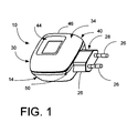
- FIG. 1 is a perspective top view of electrical apparatus with a cover embodying the present invention for manual retraction and housing of the electrical cable.
- FIG. 2 is a schematic side view of the electrical apparatus showing the electrical cable passing through the closeable opening formed between the cover lip and the apparatus housing.
- FIG. 3 is a perspective view of the electrical apparatus of FIG. 1 showing the cover flipped up revealing the electrical cable that is manually retracted or withdrawn.
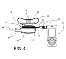
- FIG. 4 is a schematic side view of the electrical apparatus showing the cover flipped up revealing the tower around which a portion of the electrical cable is manually retracted or withdrawn with the plug end of the electrical cable connected to a mobile phone.
-
- Turning now to the drawings, Figures 1 to 4, and considering the invention in further detail, electrical apparatus generally designated 10 of the type having a transformer generally designated 12 carried in a
housing 14 includes anelectrical cable 16 having oneend 18 coupled to the transformer output and anopposite end 20 having a suitable configuredpower plug 22 for connection to an electrical device with which theelectrical apparatus 10 is used. Theelectrical apparatus 10 includes anelectrical plug 24 having suitably configured and arrangedprongs 26 arranged for insertion and electrical connection with a commercial AC power outlet (not shown). Theelectrical plug 24 is configured and arranged to be integral with thehousing 14 such that thehousing 14 andelectrical plug 24 form and define aunitary assembly 28. Further, theelectrical plug 24 may alternately be located and positioned at any desired location on the housing suitable to permit insertion of theprongs 26 into a power outlet. It will also be noted by those skilled in the art that there are many different prong arrangements and configurations to accommodate the electrical power distribution schemes as used in various different countries and accordingly all such prong and plug arrangements are contemplated by the present invention. - A cover generally designated 30 is arranged and located on an
outer surface 32 of thehousing 14. Thecover 30 has anouter surface 34 and aninner surface 36. Thecover 30 has an outerperipheral edge 40 and a innerperipheral edge 42 in a spaced relation with the outerperipheral edge 40 defining an open end of thecover 30 therebetween generally designated 43 and terminating substantially at theouter surface 32 of thehousing 14. Thecover 30 may be of any desired geometric shape and contour having a continuous wall portion with aninterior wall 44 extending to anouter wall 46 and defining aninterior cavity 38 between the coverinner surface 36 and theouter surface 32 of thehousing 14. - The cover
inner surface 36 along theinterior wall 44 defines a tower-like structure generally designated 48 around which theelectrical cable 16 is manually retracted and wound such that the retractedelectrical cable 16 is stored within theinterior cavity 38 as best illustrated in Fig. 2. Thecover 30 is made of a suitable resilient deformable material having shape retention memory characteristics such that a closeable opening generally designated 50 is formed between the lip of the outerperipheral edge 40 of the cover following along the path defined between the outerperipheral edge 40 and thehousing 14. The cover material may be of any material well known to those skilled in the art or future developed material to carry out the intended function. Theelectrical cable 16 passes through and is manually guided along thecloseable opening 50 and wound on to thetower 48 to retract the electrical cable. Theelectrical cable 16 may likewise be manually withdrawn through thecloseable opening 50 to uncoil the cable from thetower 48 to pay off a desired length of the electrical cable. - The
cover 30 may alternately be flipped up as illustrated in FIGS. 3 and 4 such that the outerperipheral edge 40 is not in contact with thesurface 32 of thehousing 14 to reveal thetower 48 around which theelectrical cable 16 may be manually retracted and wound after which thecover 30 is flipped down such that the outerperipheral edge 40 is in contact with theouter surface 32 of thehousing 14 thereby forming and defining theinterior cavity 38 for retractably housing the electrical cable when the electrical apparatus is not in use. Likewise, thecover 30 may be flipped up so that theelectrical cable 16 may be manually uncoiled from thetower 48 to pay off the desired length of the electrical cable. Thecover 30 is then flipped down such that theperipheral edge 40 is in contact with theouter surface 32 of thehousing 14 whereby thecover 30 returns to its original shape due to the memory retention characteristic of the material forming thecover 30. - It will be recognized that the
electrical apparatus 10 may include atransformer 12 as illustrated in the dash-line box in Fig. 2 or may further include suitable electronic circuitry defining means to function as a charger or a switched-mode power converter or other desired operational electrical circuit means to provide the required power to an electronic device with which theelectrical apparatus 10 is used. For example, the electronic device may be a mobile phone as shown in phantom in Fig. 4 and generally designated 52. - It will be further recognized that the cross-sectional geometric shape of the
cover 30 may be that other than shown in the figures and for example may be doughnut shaped, trapezoidal shaped, rhomboid shaped, or other desired suitable shape and configuration to accommodate the housing with which the cover is utilized. - Electrical apparatus characterized by a cover integral with and located on an outer surface of the transformer housing and defining an interior cavity for housing a manually retracted electrical cable has been described above in several preferred embodiments. It will be recognized and appreciated that numerous modifications and alterations may be made by those skilled in the art without departing from the spirit and scope of the invention. Therefore, the invention has been described by way of illustration rather than limitation.
Claims (15)
- Electrical apparatus of the type having a transformer carried in a housing and an electrical cable for coupling the transformer output to an electrical device, the improvement characterized by a cover located on an outer surface of the transformer housing and an interior cavity defined between the inner surface of the cover and the transformer housing outer surface for retractably housing the electrical cable within said interior cavity when the electrical apparatus is not in use, and such that, when in use, a desired length of the electrical cable is withdrawn from said interior cavity for connection to the electrical device.
- The electrical apparatus defined in claim 1 further characterized in that said cover is made of a resilient deformable material having a shape retention memory wherein said cover is flipped up away from the transformer housing outer surface so that the inner surface of the cover faces outward and a portion of the inner surface of the cover juxtapositioned the transformer housing outer surface defining a tower around which said electrical cable is manually retracted and wound, said cover being flipped down toward the transformer housing outer surface retaining the retracted electrical cable.
- The electrical apparatus defined in claim 2 further characterized in that said cover is flipped-up to manually pay-off a desired length of the electrical cable.
- The electrical apparatus defined in claim 1 further characterized in that a closeable opening is defined along and between the peripheral lip of the-cover and the transformer housing outer surface through which closeable opening said electrical cable is manually retracted into the interior cavity and wound around a tower defined within the interior cavity.
- The electrical apparatus defined in claim 4 further characterized in that said electrical cable passes through said closeable opening when manually uncoiled from said tower to pay-off a desired length of the electrical cable.
- The electrical apparatus as defined in claim 1 further characterized by an electrical plug integral with the housing for coupling a source of commercial electrical power to the transformer input.
- The electrical apparatus as defined in claim 6 further characterized in that said apparatus is a charger.
- The electrical apparatus as defined in claim 6 further characterized in that said apparatus is a charger and said electrical device is a mobile phone.
- The electrical apparatus as defined in claim 6 further characterized in the said apparatus is a switched mode power converter and said electrical device is a mobile phone.
- The electrical apparatus as defined in claim 1 further characterized in that said apparatus is an AC adapter.
- Electrical apparatus comprising:a housing for carrying a transformer having an input and output;an electrical plug integral with said housing for coupling an AC commercial voltage outlet to the transformer input;an electrical cable having one end coupled to the transformer output and an opposite end terminated in a suitable power plug for coupling the transformer output to a desired electronic device;a cover made of a resilient deformable material having shape retention memory characteristics located integral with and on an outer surface of the housing;an interior cavity defined between the inner surface of the cover and the outer surface of the housing, said interior cavity further being defined by a continuous wall comprising an inner peripheral wall portion and an outer peripheral wall portion spaced from the inner peripheral wall portion, said inner peripheral wall portion juxtapositioned the housing outer surface defining a tower around which said electrical cable is manually retracted and wound for storage within said interior cavity.
- In an electrical apparatus of the type having a transformer carried in a housing and an electrical cable for coupling the transformer output to an electrical device with which the electrical device is used, a method for retractably housing the electrical cable comprising the steps of:providing a cover;locating the cover on an outer surface of the transformer housing to define an interior cavity between the inner surface of the cover and the transformer housing outer surface;retractably housing the electrical cable within the interior cavity when the electrical apparatus is not in use, andwithdrawing a desired length of the electrical cable from the interior cavity for connection to the electrical device.
- The method of claim 12 further including the steps of:providing a cover made of a resilient deformable material having a shape retention memory;flipping the cover up away from the transformer housing outer surface whereby the inner surface of the cover faces outward and a portion of the outwardly facing inner surface juxtaposed the transformer housing outer surface defines a tower;manually retracting and winding the electrical cable around the tower, andflipping the cover down toward the transformer housing outer surface to retain the retracted electrical cable.
- The method of claim 12 further including the steps of:providing a closeable opening along and between the peripheral lip of the cover and the transformer housing outer surface, andmanually retracting the electrical cable into the interior cavity through the closeable opening.
- The method of claim 14 further comprising the step of winding the electrical cable around a tower defined within the interior cavity.
Applications Claiming Priority (2)
| Application Number | Priority Date | Filing Date | Title |
|---|---|---|---|
| US646339 | 1984-08-29 | ||
| US10/646,339 US6960727B2 (en) | 2003-08-22 | 2003-08-22 | Electrical apparatus with cover for retractably housing an electrical cable connected thereto |
Publications (2)
| Publication Number | Publication Date |
|---|---|
| EP1508944A1 true EP1508944A1 (en) | 2005-02-23 |
| EP1508944B1 EP1508944B1 (en) | 2006-11-02 |
Family
ID=34063505
Family Applications (1)
| Application Number | Title | Priority Date | Filing Date |
|---|---|---|---|
| EP04103055A Expired - Lifetime EP1508944B1 (en) | 2003-08-22 | 2004-06-29 | Electrical apparatus with cover for retractably housing an electrical cable connected thereto |
Country Status (5)
| Country | Link |
|---|---|
| US (1) | US6960727B2 (en) |
| EP (1) | EP1508944B1 (en) |
| CN (1) | CN100442610C (en) |
| AT (1) | ATE344541T1 (en) |
| DE (1) | DE602004002999T2 (en) |
Cited By (2)
| Publication number | Priority date | Publication date | Assignee | Title |
|---|---|---|---|---|
| FR2906415A1 (en) * | 2006-09-22 | 2008-03-28 | Jean Jacques Bigou | Battery charger for e.g. mobile telephone, has cable exiting on bottom side of gutter case, and wound in gutter by cover and case assembly, where cable has end with connector comprising band having fixation system |
| WO2016075348A1 (en) * | 2014-11-12 | 2016-05-19 | Fabricacion De Material Electrico, S.A. | Extension cord |
Families Citing this family (20)
| Publication number | Priority date | Publication date | Assignee | Title |
|---|---|---|---|---|
| USD526272S1 (en) * | 2003-08-22 | 2006-08-08 | Nokia Corporation | Travel charger |
| US20060044754A1 (en) * | 2004-08-30 | 2006-03-02 | Kuo-Chuan Hung | External power structure for industrial thin-type computer |
| TWM281259U (en) * | 2005-05-05 | 2005-11-21 | Datastor Technology Co Ltd | External case of access apparatus with protective shield |
| TW200812166A (en) * | 2006-08-25 | 2008-03-01 | sheng-xing Liao | Transfer plug |
| TWM311219U (en) * | 2006-09-01 | 2007-05-01 | Aopen Inc | Wire-managing device |
| US20090027922A1 (en) * | 2007-07-24 | 2009-01-29 | Tracy Mark S | Power adapter |
| US7871291B2 (en) * | 2007-07-31 | 2011-01-18 | Hewlett-Packard Development Company, L.P. | Power adapter |
| ITMI20090387A1 (en) * | 2009-03-13 | 2010-09-14 | Giuriani Stefano | POWER CABLE WITH SHAPE MEMORY. |
| US20110065313A1 (en) * | 2009-09-14 | 2011-03-17 | Ming-Jhih Huang | Power cord collector for power supply |
| JP5463821B2 (en) | 2009-09-24 | 2014-04-09 | セイコーエプソン株式会社 | AC adapter unit and electronic device unit |
| WO2011043812A1 (en) * | 2009-10-08 | 2011-04-14 | Audiovox Corporation | Charging station |
| US7871292B1 (en) * | 2010-01-05 | 2011-01-18 | Innotrans Technology Co., Ltd. | Power adapter provided line winding |
| US8222861B1 (en) * | 2010-02-08 | 2012-07-17 | Lockheed Martin Corporation | Elimination of power consumption when charger/adaptor is not in use |
| WO2013006753A1 (en) | 2011-07-07 | 2013-01-10 | Voxx International Corporation | Current selectable usb charger |
| US9312704B2 (en) | 2012-01-09 | 2016-04-12 | Voxx International Corporation | USB wall plate charger |
| WO2013106308A1 (en) | 2012-01-09 | 2013-07-18 | Voxx International Corporation | Travel nightlight with usb charger |
| JP6214280B2 (en) * | 2013-08-27 | 2017-10-18 | 株式会社ケアコム | Wall unit with hook function |
| US10033294B2 (en) * | 2014-11-13 | 2018-07-24 | Ricot Riphin | Folding plug with safety cover |
| US11190035B2 (en) * | 2018-12-21 | 2021-11-30 | Adeeb SOBH | Device for charging portable electronic devices |
| US11837804B2 (en) | 2021-03-29 | 2023-12-05 | Marie L. Cardi | Protective cover for a power cord |
Citations (2)
| Publication number | Priority date | Publication date | Assignee | Title |
|---|---|---|---|---|
| JPH07263057A (en) * | 1994-03-18 | 1995-10-13 | Fujitsu Ltd | Terminal board |
| GB2318930A (en) * | 1996-10-30 | 1998-05-06 | Ipr Ind Ltd | Battery charger with reel for charging cable |
Family Cites Families (10)
| Publication number | Priority date | Publication date | Assignee | Title |
|---|---|---|---|---|
| EP0624021B1 (en) * | 1993-04-16 | 1999-11-17 | Nec Corporation | Portable telephone set with an earphone |
| JPH10143214A (en) | 1996-11-12 | 1998-05-29 | Okuma Mach Works Ltd | Numerical controller |
| US5684883A (en) * | 1996-11-26 | 1997-11-04 | E Lead Electronic Co., Ltd. | Device for receiving earphone/microphone wire of holdfree hand set |
| JPH10190798A (en) | 1996-12-25 | 1998-07-21 | Kokusai Electric Co Ltd | Mobile communication device |
| GB2328580A (en) * | 1997-08-22 | 1999-02-24 | E Lead Electronic Co Ltd | A plug/cable reel assembly for use with an earphone/microphone assembly |
| AT408703B (en) * | 1998-03-09 | 2002-02-25 | Egston Eggenburger Syst Elektr | POWER SUPPLY |
| AUPP357698A0 (en) | 1998-05-18 | 1998-06-11 | White, Simon John | Hands-free device for mobile telephones |
| CA2297237C (en) * | 2000-01-26 | 2005-11-22 | Jonie Chou | Communication adapter |
| CN2461193Y (en) * | 2000-11-13 | 2001-11-21 | 鑫腾科技股份有限公司 | Mobile phone charger that is easy to carry and pack |
| CN2489484Y (en) * | 2001-07-04 | 2002-05-01 | 东莞朋达电子有限公司 | car phone charger |
-
2003
- 2003-08-22 US US10/646,339 patent/US6960727B2/en not_active Expired - Fee Related
-
2004
- 2004-06-29 AT AT04103055T patent/ATE344541T1/en not_active IP Right Cessation
- 2004-06-29 EP EP04103055A patent/EP1508944B1/en not_active Expired - Lifetime
- 2004-06-29 DE DE602004002999T patent/DE602004002999T2/en not_active Expired - Lifetime
- 2004-08-20 CN CNB2004100642777A patent/CN100442610C/en not_active Expired - Fee Related
Patent Citations (2)
| Publication number | Priority date | Publication date | Assignee | Title |
|---|---|---|---|---|
| JPH07263057A (en) * | 1994-03-18 | 1995-10-13 | Fujitsu Ltd | Terminal board |
| GB2318930A (en) * | 1996-10-30 | 1998-05-06 | Ipr Ind Ltd | Battery charger with reel for charging cable |
Non-Patent Citations (1)
| Title |
|---|
| PATENT ABSTRACTS OF JAPAN vol. 1996, no. 02 29 February 1996 (1996-02-29) * |
Cited By (2)
| Publication number | Priority date | Publication date | Assignee | Title |
|---|---|---|---|---|
| FR2906415A1 (en) * | 2006-09-22 | 2008-03-28 | Jean Jacques Bigou | Battery charger for e.g. mobile telephone, has cable exiting on bottom side of gutter case, and wound in gutter by cover and case assembly, where cable has end with connector comprising band having fixation system |
| WO2016075348A1 (en) * | 2014-11-12 | 2016-05-19 | Fabricacion De Material Electrico, S.A. | Extension cord |
Also Published As
| Publication number | Publication date |
|---|---|
| ATE344541T1 (en) | 2006-11-15 |
| DE602004002999T2 (en) | 2007-09-06 |
| DE602004002999D1 (en) | 2006-12-14 |
| US20050042914A1 (en) | 2005-02-24 |
| EP1508944B1 (en) | 2006-11-02 |
| US6960727B2 (en) | 2005-11-01 |
| CN100442610C (en) | 2008-12-10 |
| CN1585208A (en) | 2005-02-23 |
Similar Documents
| Publication | Publication Date | Title |
|---|---|---|
| US6960727B2 (en) | Electrical apparatus with cover for retractably housing an electrical cable connected thereto | |
| US7906936B2 (en) | Rechargeable inductive charger | |
| US10594148B2 (en) | Mechanism for charging an electronic device with a retractable cord reel | |
| AU2011201146B2 (en) | Inductive power charger | |
| JPH10155245A (en) | Battery charging unit | |
| US9300123B2 (en) | Mechanism for charging an electronic device with a retractable cord reel | |
| US20210066903A1 (en) | Cable organizer | |
| CN1124428A (en) | Portable Storage for Phone Cords | |
| KR101521867B1 (en) | The portable battery charger having gender storage groove | |
| CN208015416U (en) | A kind of onboard charger for electric vehicle | |
| CN223843570U (en) | Mobile power supply | |
| CN220341624U (en) | But pull multi-head data line | |
| CN223575868U (en) | Multi-line storage device | |
| KR200300964Y1 (en) | Power connected apparatus having charger for USB port | |
| EP3371868A1 (en) | Mechanism for charging an electronic device with a retractable cord reel |
Legal Events
| Date | Code | Title | Description |
|---|---|---|---|
| PUAI | Public reference made under article 153(3) epc to a published international application that has entered the european phase |
Free format text: ORIGINAL CODE: 0009012 |
|
| AK | Designated contracting states |
Kind code of ref document: A1 Designated state(s): AT BE BG CH CY CZ DE DK EE ES FI FR GB GR HU IE IT LI LU MC NL PL PT RO SE SI SK TR |
|
| AX | Request for extension of the european patent |
Extension state: AL HR LT LV MK |
|
| 17P | Request for examination filed |
Effective date: 20050401 |
|
| 17Q | First examination report despatched |
Effective date: 20050629 |
|
| AKX | Designation fees paid |
Designated state(s): AT BE BG CH CY CZ DE DK EE ES FI FR GB GR HU IE IT LI LU MC NL PL PT RO SE SI SK TR |
|
| GRAP | Despatch of communication of intention to grant a patent |
Free format text: ORIGINAL CODE: EPIDOSNIGR1 |
|
| GRAS | Grant fee paid |
Free format text: ORIGINAL CODE: EPIDOSNIGR3 |
|
| GRAA | (expected) grant |
Free format text: ORIGINAL CODE: 0009210 |
|
| AK | Designated contracting states |
Kind code of ref document: B1 Designated state(s): AT BE BG CH CY CZ DE DK EE ES FI FR GB GR HU IE IT LI LU MC NL PL PT RO SE SI SK TR |
|
| PG25 | Lapsed in a contracting state [announced via postgrant information from national office to epo] |
Ref country code: IT Free format text: LAPSE BECAUSE OF FAILURE TO SUBMIT A TRANSLATION OF THE DESCRIPTION OR TO PAY THE FEE WITHIN THE PRESCRIBED TIME-LIMIT;WARNING: LAPSES OF ITALIAN PATENTS WITH EFFECTIVE DATE BEFORE 2007 MAY HAVE OCCURRED AT ANY TIME BEFORE 2007. THE CORRECT EFFECTIVE DATE MAY BE DIFFERENT FROM THE ONE RECORDED. Effective date: 20061102 Ref country code: SI Free format text: LAPSE BECAUSE OF FAILURE TO SUBMIT A TRANSLATION OF THE DESCRIPTION OR TO PAY THE FEE WITHIN THE PRESCRIBED TIME-LIMIT Effective date: 20061102 Ref country code: CZ Free format text: LAPSE BECAUSE OF FAILURE TO SUBMIT A TRANSLATION OF THE DESCRIPTION OR TO PAY THE FEE WITHIN THE PRESCRIBED TIME-LIMIT Effective date: 20061102 Ref country code: LI Free format text: LAPSE BECAUSE OF FAILURE TO SUBMIT A TRANSLATION OF THE DESCRIPTION OR TO PAY THE FEE WITHIN THE PRESCRIBED TIME-LIMIT Effective date: 20061102 Ref country code: CH Free format text: LAPSE BECAUSE OF FAILURE TO SUBMIT A TRANSLATION OF THE DESCRIPTION OR TO PAY THE FEE WITHIN THE PRESCRIBED TIME-LIMIT Effective date: 20061102 Ref country code: PL Free format text: LAPSE BECAUSE OF FAILURE TO SUBMIT A TRANSLATION OF THE DESCRIPTION OR TO PAY THE FEE WITHIN THE PRESCRIBED TIME-LIMIT Effective date: 20061102 Ref country code: SK Free format text: LAPSE BECAUSE OF FAILURE TO SUBMIT A TRANSLATION OF THE DESCRIPTION OR TO PAY THE FEE WITHIN THE PRESCRIBED TIME-LIMIT Effective date: 20061102 Ref country code: BE Free format text: LAPSE BECAUSE OF FAILURE TO SUBMIT A TRANSLATION OF THE DESCRIPTION OR TO PAY THE FEE WITHIN THE PRESCRIBED TIME-LIMIT Effective date: 20061102 Ref country code: RO Free format text: LAPSE BECAUSE OF FAILURE TO SUBMIT A TRANSLATION OF THE DESCRIPTION OR TO PAY THE FEE WITHIN THE PRESCRIBED TIME-LIMIT Effective date: 20061102 Ref country code: AT Free format text: LAPSE BECAUSE OF FAILURE TO SUBMIT A TRANSLATION OF THE DESCRIPTION OR TO PAY THE FEE WITHIN THE PRESCRIBED TIME-LIMIT Effective date: 20061102 |
|
| REG | Reference to a national code |
Ref country code: GB Ref legal event code: FG4D |
|
| REG | Reference to a national code |
Ref country code: IE Ref legal event code: FG4D |
|
| REG | Reference to a national code |
Ref country code: CH Ref legal event code: EP |
|
| REF | Corresponds to: |
Ref document number: 602004002999 Country of ref document: DE Date of ref document: 20061214 Kind code of ref document: P |
|
| PG25 | Lapsed in a contracting state [announced via postgrant information from national office to epo] |
Ref country code: DK Free format text: LAPSE BECAUSE OF FAILURE TO SUBMIT A TRANSLATION OF THE DESCRIPTION OR TO PAY THE FEE WITHIN THE PRESCRIBED TIME-LIMIT Effective date: 20070202 Ref country code: SE Free format text: LAPSE BECAUSE OF FAILURE TO SUBMIT A TRANSLATION OF THE DESCRIPTION OR TO PAY THE FEE WITHIN THE PRESCRIBED TIME-LIMIT Effective date: 20070202 Ref country code: BG Free format text: LAPSE BECAUSE OF FAILURE TO SUBMIT A TRANSLATION OF THE DESCRIPTION OR TO PAY THE FEE WITHIN THE PRESCRIBED TIME-LIMIT Effective date: 20070202 |
|
| PG25 | Lapsed in a contracting state [announced via postgrant information from national office to epo] |
Ref country code: ES Free format text: LAPSE BECAUSE OF FAILURE TO SUBMIT A TRANSLATION OF THE DESCRIPTION OR TO PAY THE FEE WITHIN THE PRESCRIBED TIME-LIMIT Effective date: 20070213 |
|
| ET | Fr: translation filed | ||
| PG25 | Lapsed in a contracting state [announced via postgrant information from national office to epo] |
Ref country code: PT Free format text: LAPSE BECAUSE OF FAILURE TO SUBMIT A TRANSLATION OF THE DESCRIPTION OR TO PAY THE FEE WITHIN THE PRESCRIBED TIME-LIMIT Effective date: 20070402 |
|
| REG | Reference to a national code |
Ref country code: CH Ref legal event code: PL |
|
| PLBE | No opposition filed within time limit |
Free format text: ORIGINAL CODE: 0009261 |
|
| STAA | Information on the status of an ep patent application or granted ep patent |
Free format text: STATUS: NO OPPOSITION FILED WITHIN TIME LIMIT |
|
| 26N | No opposition filed |
Effective date: 20070803 |
|
| PG25 | Lapsed in a contracting state [announced via postgrant information from national office to epo] |
Ref country code: MC Free format text: LAPSE BECAUSE OF NON-PAYMENT OF DUE FEES Effective date: 20070630 |
|
| PG25 | Lapsed in a contracting state [announced via postgrant information from national office to epo] |
Ref country code: GR Free format text: LAPSE BECAUSE OF FAILURE TO SUBMIT A TRANSLATION OF THE DESCRIPTION OR TO PAY THE FEE WITHIN THE PRESCRIBED TIME-LIMIT Effective date: 20070203 |
|
| PG25 | Lapsed in a contracting state [announced via postgrant information from national office to epo] |
Ref country code: IE Free format text: LAPSE BECAUSE OF NON-PAYMENT OF DUE FEES Effective date: 20070629 |
|
| PG25 | Lapsed in a contracting state [announced via postgrant information from national office to epo] |
Ref country code: EE Free format text: LAPSE BECAUSE OF FAILURE TO SUBMIT A TRANSLATION OF THE DESCRIPTION OR TO PAY THE FEE WITHIN THE PRESCRIBED TIME-LIMIT Effective date: 20061102 |
|
| PG25 | Lapsed in a contracting state [announced via postgrant information from national office to epo] |
Ref country code: CY Free format text: LAPSE BECAUSE OF FAILURE TO SUBMIT A TRANSLATION OF THE DESCRIPTION OR TO PAY THE FEE WITHIN THE PRESCRIBED TIME-LIMIT Effective date: 20061102 Ref country code: LU Free format text: LAPSE BECAUSE OF NON-PAYMENT OF DUE FEES Effective date: 20070629 |
|
| PG25 | Lapsed in a contracting state [announced via postgrant information from national office to epo] |
Ref country code: HU Free format text: LAPSE BECAUSE OF FAILURE TO SUBMIT A TRANSLATION OF THE DESCRIPTION OR TO PAY THE FEE WITHIN THE PRESCRIBED TIME-LIMIT Effective date: 20070503 Ref country code: TR Free format text: LAPSE BECAUSE OF FAILURE TO SUBMIT A TRANSLATION OF THE DESCRIPTION OR TO PAY THE FEE WITHIN THE PRESCRIBED TIME-LIMIT Effective date: 20061102 |
|
| PGFP | Annual fee paid to national office [announced via postgrant information from national office to epo] |
Ref country code: DE Payment date: 20120627 Year of fee payment: 9 Ref country code: NL Payment date: 20120614 Year of fee payment: 9 |
|
| PGFP | Annual fee paid to national office [announced via postgrant information from national office to epo] |
Ref country code: FR Payment date: 20120619 Year of fee payment: 9 Ref country code: GB Payment date: 20120627 Year of fee payment: 9 Ref country code: FI Payment date: 20120612 Year of fee payment: 9 |
|
| REG | Reference to a national code |
Ref country code: NL Ref legal event code: V1 Effective date: 20140101 |
|
| GBPC | Gb: european patent ceased through non-payment of renewal fee |
Effective date: 20130629 |
|
| PG25 | Lapsed in a contracting state [announced via postgrant information from national office to epo] |
Ref country code: FI Free format text: LAPSE BECAUSE OF NON-PAYMENT OF DUE FEES Effective date: 20130629 |
|
| REG | Reference to a national code |
Ref country code: FR Ref legal event code: ST Effective date: 20140228 |
|
| REG | Reference to a national code |
Ref country code: DE Ref legal event code: R119 Ref document number: 602004002999 Country of ref document: DE Effective date: 20140101 |
|
| PG25 | Lapsed in a contracting state [announced via postgrant information from national office to epo] |
Ref country code: GB Free format text: LAPSE BECAUSE OF NON-PAYMENT OF DUE FEES Effective date: 20130629 Ref country code: DE Free format text: LAPSE BECAUSE OF NON-PAYMENT OF DUE FEES Effective date: 20140101 Ref country code: NL Free format text: LAPSE BECAUSE OF NON-PAYMENT OF DUE FEES Effective date: 20140101 |
|
| PG25 | Lapsed in a contracting state [announced via postgrant information from national office to epo] |
Ref country code: FR Free format text: LAPSE BECAUSE OF NON-PAYMENT OF DUE FEES Effective date: 20130701 |