EP1508843A1 - Numerical control apparatus - Google Patents
Numerical control apparatus Download PDFInfo
- Publication number
- EP1508843A1 EP1508843A1 EP04254843A EP04254843A EP1508843A1 EP 1508843 A1 EP1508843 A1 EP 1508843A1 EP 04254843 A EP04254843 A EP 04254843A EP 04254843 A EP04254843 A EP 04254843A EP 1508843 A1 EP1508843 A1 EP 1508843A1
- Authority
- EP
- European Patent Office
- Prior art keywords
- axis
- tool
- amount
- linear moving
- movement
- Prior art date
- Legal status (The legal status is an assumption and is not a legal conclusion. Google has not performed a legal analysis and makes no representation as to the accuracy of the status listed.)
- Granted
Links
Images


Classifications
-
- G—PHYSICS
- G05—CONTROLLING; REGULATING
- G05B—CONTROL OR REGULATING SYSTEMS IN GENERAL; FUNCTIONAL ELEMENTS OF SUCH SYSTEMS; MONITORING OR TESTING ARRANGEMENTS FOR SUCH SYSTEMS OR ELEMENTS
- G05B19/00—Program-control systems
- G05B19/02—Program-control systems electric
- G05B19/18—Numerical control [NC], i.e. automatically operating machines, in particular machine tools, e.g. in a manufacturing environment, so as to execute positioning, movement or co-ordinated operations by means of program data in numerical form
- G05B19/408—Numerical control [NC], i.e. automatically operating machines, in particular machine tools, e.g. in a manufacturing environment, so as to execute positioning, movement or co-ordinated operations by means of program data in numerical form characterised by data handling or data format, e.g. reading, buffering or conversion of data
- G05B19/4086—Coordinate conversions; Other special calculations
-
- G—PHYSICS
- G05—CONTROLLING; REGULATING
- G05B—CONTROL OR REGULATING SYSTEMS IN GENERAL; FUNCTIONAL ELEMENTS OF SUCH SYSTEMS; MONITORING OR TESTING ARRANGEMENTS FOR SUCH SYSTEMS OR ELEMENTS
- G05B2219/00—Program-control systems
- G05B2219/30—Nc systems
- G05B2219/33—Director till display
- G05B2219/33269—Convert cartesian to machine coordinates
-
- Y—GENERAL TAGGING OF NEW TECHNOLOGICAL DEVELOPMENTS; GENERAL TAGGING OF CROSS-SECTIONAL TECHNOLOGIES SPANNING OVER SEVERAL SECTIONS OF THE IPC; TECHNICAL SUBJECTS COVERED BY FORMER USPC CROSS-REFERENCE ART COLLECTIONS [XRACs] AND DIGESTS
- Y10—TECHNICAL SUBJECTS COVERED BY FORMER USPC
- Y10T—TECHNICAL SUBJECTS COVERED BY FORMER US CLASSIFICATION
- Y10T408/00—Cutting by use of rotating axially moving tool
- Y10T408/08—Cutting by use of rotating axially moving tool with means to regulate operation by use of templet, tape, card, or other replaceable information supply
-
- Y—GENERAL TAGGING OF NEW TECHNOLOGICAL DEVELOPMENTS; GENERAL TAGGING OF CROSS-SECTIONAL TECHNOLOGIES SPANNING OVER SEVERAL SECTIONS OF THE IPC; TECHNICAL SUBJECTS COVERED BY FORMER USPC CROSS-REFERENCE ART COLLECTIONS [XRACs] AND DIGESTS
- Y10—TECHNICAL SUBJECTS COVERED BY FORMER USPC
- Y10T—TECHNICAL SUBJECTS COVERED BY FORMER US CLASSIFICATION
- Y10T408/00—Cutting by use of rotating axially moving tool
- Y10T408/91—Machine frame
- Y10T408/93—Machine frame including pivotally mounted tool-carrier
-
- Y—GENERAL TAGGING OF NEW TECHNOLOGICAL DEVELOPMENTS; GENERAL TAGGING OF CROSS-SECTIONAL TECHNOLOGIES SPANNING OVER SEVERAL SECTIONS OF THE IPC; TECHNICAL SUBJECTS COVERED BY FORMER USPC CROSS-REFERENCE ART COLLECTIONS [XRACs] AND DIGESTS
- Y10—TECHNICAL SUBJECTS COVERED BY FORMER USPC
- Y10T—TECHNICAL SUBJECTS COVERED BY FORMER US CLASSIFICATION
- Y10T409/00—Gear cutting, milling, or planing
- Y10T409/30—Milling
- Y10T409/30084—Milling with regulation of operation by templet, card, or other replaceable information supply
- Y10T409/300896—Milling with regulation of operation by templet, card, or other replaceable information supply with sensing of numerical information and regulation without mechanical connection between sensing means and regulated means [i.e., numerical control]
-
- Y—GENERAL TAGGING OF NEW TECHNOLOGICAL DEVELOPMENTS; GENERAL TAGGING OF CROSS-SECTIONAL TECHNOLOGIES SPANNING OVER SEVERAL SECTIONS OF THE IPC; TECHNICAL SUBJECTS COVERED BY FORMER USPC CROSS-REFERENCE ART COLLECTIONS [XRACs] AND DIGESTS
- Y10—TECHNICAL SUBJECTS COVERED BY FORMER USPC
- Y10T—TECHNICAL SUBJECTS COVERED BY FORMER US CLASSIFICATION
- Y10T409/00—Gear cutting, milling, or planing
- Y10T409/30—Milling
- Y10T409/306664—Milling including means to infeed rotary cutter toward work
- Y10T409/307224—Milling including means to infeed rotary cutter toward work with infeed control means energized in response to activator stimulated by condition sensor
-
- Y—GENERAL TAGGING OF NEW TECHNOLOGICAL DEVELOPMENTS; GENERAL TAGGING OF CROSS-SECTIONAL TECHNOLOGIES SPANNING OVER SEVERAL SECTIONS OF THE IPC; TECHNICAL SUBJECTS COVERED BY FORMER USPC CROSS-REFERENCE ART COLLECTIONS [XRACs] AND DIGESTS
- Y10—TECHNICAL SUBJECTS COVERED BY FORMER USPC
- Y10T—TECHNICAL SUBJECTS COVERED BY FORMER US CLASSIFICATION
- Y10T409/00—Gear cutting, milling, or planing
- Y10T409/30—Milling
- Y10T409/306664—Milling including means to infeed rotary cutter toward work
- Y10T409/307672—Angularly adjustable cutter head
Definitions
- the present invention relates to a numerical control apparatus which controls a machine tool having two linear moving axes orthogonal to each other and a pivot axis.
- a machine tool for machining a three-dimensional-shaped workpiece a machine having an actuator for linearly operating at least three orthogonal axes is used.
- a drive system such as a guide and a ball screw applied to moving ranges of the axes are required. Even though the drive system is required to be reduced in size, the drive system cannot be easily reduced in size.
- a machine tool which includes a simple configuration, in place of the three orthogonal linear moving axes, to make it possible to achieve a reduction in size and to perform machining of an arbitrary three-dimensional shape equivalent to machining performed by three orthogonal linear moving axes is not known.
- the present invention relates to a numerical control apparatus which controls an operation of a machine tool, which uses a pivot axis in place of one of three linear moving axes orthogonal to each other and performs three-dimensional machining, according to a command program.
- the machine tool controlled by the numerical control apparatus comprises: a first linear moving axis; a second linear moving axis orthogonal to the first linear moving axis; a pivot axis for rotating a pivot member about the first linear moving axis or a axis parallel to the first linear moving axis; and a tool arranged at the distal end of the pivot member.
- a command program an operation route in a three-dimensional orthogonal coordinate system is commanded.
- the numerical control apparatus comprises means for interpolating the operation route in the three-dimensional orthogonal coordinate system commanded by the command program in a predetermined cycle and calculating an amount of movement between interpolation points as interpolation components on the three-dimensional orthogonal coordinate system; means for calculating an amount of rotation of the tool about the pivot axis required for moving the tool by an interpolation component for a third axis orthogonal to the first and second linear moving axes; and means for calculating an amount of movement of the tool in the direction of the second linear moving axis, caused by the rotation of the tool by the calculated amount of rotation, as an amount of correction.
- An amount of movement of an interpolation component of the first linear moving axis is outputted to the first linear moving axis, an amount of movement corrected by the amount of correction is outputted to the second linear moving axis, and the amount of rotation is outputted to the pivot axis, in a predetermined cycle, respectively.
- a machine tool can be operated along a commanded route and at a commanded speed.
- a machine tool in which one axis of orthogonal axes is replaced with a pivot axis can be driven and controlled by a command program for a conventional machine tool having three orthogonal linear moving axes. Therefore, the machine tool can be reduced in size and simplified.
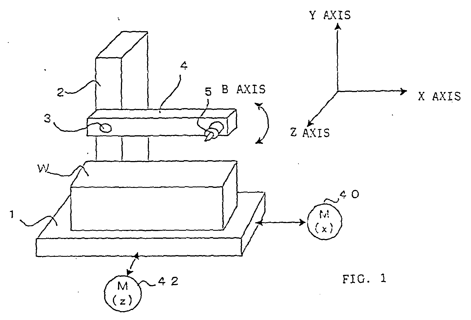
- FIG. 1 is a schematic diagram of an example of a machine tool to which a numerical control apparatus according to the present invention is applied.
- a table 1 moves in an X-axis direction and a Z-axis direction orthogonal to the X-axis direction by driving an X-axis servo motor 40 and a Z-axis servo motor 42.
- a shaft 3 extending in a direction parallel to the Z axis is arranged on a support 2, and a pivot member 4 is provided on the shaft 3 so as to rotate about the axis of the shaft 3.
- the pivot member 4 is rotationally driven by a servo motor (not shown).
- a tool 5 is fixed to the distal end of the pivot member 4, and the tool 5 is designed to be driven by a spindle motor (not shown).
- An axis about which the pivot member 4 is rotated about the shaft 3 to move the tool 5 is called a pivot axis B.
- a servo motor which drives the pivot axis B is called a B-axis servo motor.
- the tool 5 on the pivot member 4 is rotated by the B-axis servo motor on an
- the pivot member 4 having the tool 5 arranged at the distal end thereof is rotated about the pivot axis B (shaft 3) parallel to the Z axis, with respect to a workpiece W on the table 1 driven by the X-axis servo motor 40 and the Z-axis servo motor 42.
- the pivot member 4 is rotated about the pivot axis B, the position of the tool 5 shifts in the X-axis direction and the Y-axis direction orthogonal to the X-axis direction and the Z-axis direction.
- the tool 5 moves in the X-axis, Y-axis, and Z-axis direction with respect to the workpiece W to make it possible to three-dimensionally machine the workpiece W.
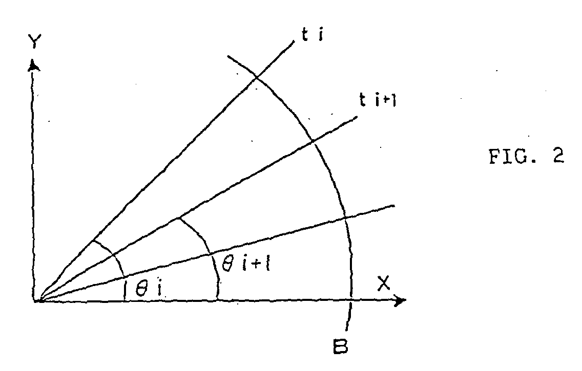
- FIG. 2 is a diagram for explaining calculation of the position of the tool 5 when rotation of the pivot axis B is interpolated at predetermined intervals.
- the rotating angle of the pivot axis B is equally divided by interpolation. It is assumed that a rotating angle is ⁇ i at time ti and that a rotating angle is ⁇ i+1 at time ti+1.
- R a distance between the center of rotation (shaft 3) of the pivot axis B and the center of rotation of the tool 5
- the tool 5 relatively moves in the Y-axis direction by R. (sin ⁇ i+1 - sin ⁇ i) with respect to the workpiece W and moves in the X-axis direction by R.(cos ⁇ i+1 - cos ⁇ i) in a period of time between time ti and time ti+1.
- a moving command to the Y-axis serving as a virtual axis is outputted, in place of a rotational command to the pivot axis B, like a moving command to a machine tool on a conventional orthogonal coordinate system.
- a moving command for a workpiece in a command program or the like is formed just like a moving command in a command program which is formed according to a conventional orthogonal coordinate system.
- interpolation processes are performed in the X-axis, Y-axis and Z-axis directions, based on a moving speed and a moving position commanded by a command program, to calculate interpolated amounts of movement in the respective directions.
- an amount of rotation of the pivot axis B is calculated from an amount of movement to the Y-axis serving as a virtual axis.
- the tool 5 on the pivot member 4 can be moved in the Y-axis direction at a commanded predetermined speed.
- FIG. 4 is a main block diagram of a numerical control apparatus according to an embodiment of the present invention.
- This embodiment is an example of a numerical control apparatus which controls a machine tool comprising a linear moving axis being an X axis shown in FIG. 1, a linear moving axis being a Z axis orthogonal to the X axis, a pivot axis B rotating a pivot member about the Z axis or an axis parallel to the Z axis, and a tool arranged at the distal end of the pivot member to have the machine tool machine a three-dimensional shape for a workpiece.
- a CPU 11 is a processor for entirely controlling a numerical control apparatus 10.
- a memory 12 a display/input device 13, a PMC (Programmable Machine Controller) 14, X-, B-, and Z-axis control circuits 20, 21, and 22, and a main axis control circuit 60 are connected to the CPU 11 through a bus 15.
- the CPU 11 reads the system program stored in the memory 12 through the bus 15, and controls the whole numerical control apparatus according to the system program.
- Various data inputted by an operator through the display/input device 13 constituted by an input device for inputting commands and data from the display, the keyboard, and the like, a command program formed by using the display/input device 13, and a command program inputted though an interface (not shown) are stored in the memory 12.
- a PMC 14 inputs a signal to and outputs a signal from an auxiliary device of the machine tool by a sequence program stored in a numerical control apparatus 100 to control the machine tool.
- the axis control circuits 20 to 22 for the respective axes receive moving commands of the respective axes from the CPU 11 to output the commands of the axes to servo amplifiers 30 to 32, respectively.
- the servo amplifiers 30 to 32 receive the commands to drive servo motors 40 to 42 of the respective axes.
- the servo motors 40 to 42 of the respective axes have position/speed detectors 50 to 52 built-in, and the axis control circuits 30 to 33 receive position/speed feedback signals from the position/speed detectors 50 to 52 to perform feedback control of the positions and the speeds.
- the main axis control circuit 60 receives a main axis rotation command to output a spindle speed signal to a main amplifier 61.
- the main amplifier 61 receives the spindle speed signal to rotate a spindle motor 62 at a commanded rotating speed, and the tool 5 arranged on the main axis is rotated.
- a position encoder (not shown) is provided on the main axis. According to a feedback signal from the position encoder, the main axis control circuit 60 performs feedback control of the rotating speed of the main axis.
- the configuration of the numerical control apparatus described above is the same as that of the conventional numerical control apparatus.
- the command program for machining a workpiece with the machine tool controlled by the numerical control apparatus is the same as that formed for a machine tool using conventional three orthogonal linear moving axes. More specifically, the command program for machining a three-dimensional shape is commanded as a command of three orthogonal X, Y, and Z axes as in the conventional art.
- the command program is different from the conventional command program in that the CPU 11, after calculating amounts of interpolation movement ⁇ X, ⁇ Y, and ⁇ Z to the three orthogonal axes X, Y, and Z by an interpolation process, calculates a rotating angle ⁇ of the pivot axis B and an amount of movement ⁇ x for canceling X-axis movement caused by rotation of the pivot axis B, and outputs moving commands ⁇ X+ ⁇ x, ⁇ , and ⁇ Z to the X-axis control circuit, B-axis control circuit, and the Z-axis control circuit, respectively.
- FIG. 5 is a flow chart showing an algorithm of processes executed by the CPU 11 of the embodiment on the basis of a command program.
- a pre-process in step S1 and processes in step S2 and the subsequent steps are performed by different tasks
- the pre-process in step S1 is performed by a pre-process task
- the processes in step S2 and subsequent steps are executed every interpolation cycle.
- these processes are expressed by the same flow chart.
- the CPU 11 reads one block from a command program, performs the same pre-process as the conventional pre-process, and forms block data of an executable form which can perform an interpolation distribution process (step S1).
- the CPU 11 executes the same interpolation process as that in the conventional art on the basis of the block data of the executable form to calculate amounts of feeding ⁇ X, ⁇ Y, and ⁇ Z in the orthogonal X-, Y-, and Z-axis directions (step S2).
- the processes executed up to this step are the same as those in control of a conventional machine tool having through three orthogonal linear moving axes.
- an amount of X-axis correction ⁇ x by which the tool 5 is moved in the reverse direction to cancel the X-axis movement caused by rotating the pivot axis B by an angle ⁇ is calculated by the equation (2) (step S4).
- the rotating angle ⁇ i+1 of the pivot axis B calculated in step S3 is stored in the register to be used as a rotating position ⁇ i at the previous cycle in the next interpolation cycle (step S5).
- the value obtained by adding the amount of correction ⁇ x to the amount of movement calculated in step S2 is outputted to the X-axis control circuit 20 as a moving command at the current cycle.
- the amount of rotation ⁇ calculated in step S3 is outputted to the axis control circuit 21 of the pivot axis B, and the amount of movement ⁇ Z calculated in step S2 is outputted to the Z-axis control circuit 22 (step S6).
- the respective axis control circuits 20 to 22 perform feedback control of positions and speeds on the basis of the received moving commands and the position/speed feedback signals fed back from the position/speed detectors 50 to 52. Furthermore, the axis control circuits 20 to 22 perform current loop control to drive the servo motors 40 to 42 through the servo amplifiers 30 to 32, respectively.
- steps S2 to S6 are performed every interpolation cycle. Upon completion of the movement for one commanded block, the interpolation process is performed in a similar way by using pre-processed data in the next block.
- the tool 5 moves in the X-, Y-, and Z-axis directions with respect to the workpiece W along a route and at a speed each commanded by the command program, and machines the workpiece.
- the machine tool comprises the X-and Z-axis linear moving axes.
- the Y axis orthogonal to these linear moving axes is defined as a virtual axis, and the pivot member is rotated about an axis (pivot axis) parallel to the Z axis, i.e., on the X-Y plane.
- the machine tool is moved in the Y-axis direction by the rotation of the pivot member, and an X-axis moving command is corrected.
- the pivot member comprising the tool arranged at the distal end thereof is rotated about the first linear moving axis of the first and second linear moving axes orthogonal to each other or an axis parallel to the first linear moving axis, so that the tool is moved in the third-axis direction orthogonal to the first and second linear moving axes and a moving command to the second linear moving axis is corrected to cancel movement of the tool in the direction of the second linear moving axis caused by the rotation of the pivot member.
Landscapes
- Engineering & Computer Science (AREA)
- Human Computer Interaction (AREA)
- Manufacturing & Machinery (AREA)
- Physics & Mathematics (AREA)
- General Physics & Mathematics (AREA)
- Automation & Control Theory (AREA)
- Numerical Control (AREA)
Abstract
Description
- The present invention relates to a numerical control apparatus which controls a machine tool having two linear moving axes orthogonal to each other and a pivot axis.
- As a machine tool for machining a three-dimensional-shaped workpiece, a machine having an actuator for linearly operating at least three orthogonal axes is used. In this case, a drive system such as a guide and a ball screw applied to moving ranges of the axes are required. Even though the drive system is required to be reduced in size, the drive system cannot be easily reduced in size. A machine tool which includes a simple configuration, in place of the three orthogonal linear moving axes, to make it possible to achieve a reduction in size and to perform machining of an arbitrary three-dimensional shape equivalent to machining performed by three orthogonal linear moving axes is not known.
- In order to reduce the size of the above machine tool or to simplify the drive system, an easy and simple drive system is necessary in place of the linear axes. If an actuator which does not use linear moving axes is used, formation of a program for a numerical control apparatus in which commands for workpiece machining are formed in three orthogonal moving directions in workpiece machining for a three-dimensional shape must be changed, usability is also deteriorated, and inconvenience increases.
- The present invention relates to a numerical control apparatus which controls an operation of a machine tool, which uses a pivot axis in place of one of three linear moving axes orthogonal to each other and performs three-dimensional machining, according to a command program.
- The machine tool controlled by the numerical control apparatus comprises: a first linear moving axis; a second linear moving axis orthogonal to the first linear moving axis; a pivot axis for rotating a pivot member about the first linear moving axis or a axis parallel to the first linear moving axis; and a tool arranged at the distal end of the pivot member. In the command program, an operation route in a three-dimensional orthogonal coordinate system is commanded.
- The numerical control apparatus comprises means for interpolating the operation route in the three-dimensional orthogonal coordinate system commanded by the command program in a predetermined cycle and calculating an amount of movement between interpolation points as interpolation components on the three-dimensional orthogonal coordinate system; means for calculating an amount of rotation of the tool about the pivot axis required for moving the tool by an interpolation component for a third axis orthogonal to the first and second linear moving axes; and means for calculating an amount of movement of the tool in the direction of the second linear moving axis, caused by the rotation of the tool by the calculated amount of rotation, as an amount of correction. An amount of movement of an interpolation component of the first linear moving axis is outputted to the first linear moving axis, an amount of movement corrected by the amount of correction is outputted to the second linear moving axis, and the amount of rotation is outputted to the pivot axis, in a predetermined cycle, respectively.
- With the above configuration, on the basis of the command program commanded in the three-dimensional orthogonal coordinate system, a machine tool can be operated along a commanded route and at a commanded speed.
- A machine tool in which one axis of orthogonal axes is replaced with a pivot axis can be driven and controlled by a command program for a conventional machine tool having three orthogonal linear moving axes. Therefore, the machine tool can be reduced in size and simplified.
- The above and other objects and characteristic features of the present invention will be apparent from the following description of embodiments explained with reference to the accompanying drawings. Of these drawings:
- FIG. 1 is a schematic diagram of an example of a machine tool to which a numerical control apparatus according to the present invention is applied;
- FIG. 2 is a diagram for explaining a position of a pivot axis calculated by linearly interpolating the pivot axis in units of time for interpolation;
- FIG. 3 is a diagram for explaining a position of the pivot axis calculated by linearly interpolating a pivot axis in a Y-axis direction of virtual linear movement;
- FIG. 4 is a main block diagram of a numerical control apparatus according to an embodiment of the present invention; and
- FIG. 5 is a flow chart showing processes performed by a CPU of the numerical control apparatus in FIG. 4 on the basis of a command program.
-
- FIG. 1 is a schematic diagram of an example of a machine tool to which a numerical control apparatus according to the present invention is applied.
- A table 1 moves in an X-axis direction and a Z-axis direction orthogonal to the X-axis direction by driving an
X-axis servo motor 40 and a Z-axis servo motor 42. A shaft 3 extending in a direction parallel to the Z axis is arranged on asupport 2, and apivot member 4 is provided on the shaft 3 so as to rotate about the axis of the shaft 3. Thepivot member 4 is rotationally driven by a servo motor (not shown). Atool 5 is fixed to the distal end of thepivot member 4, and thetool 5 is designed to be driven by a spindle motor (not shown). An axis about which thepivot member 4 is rotated about the shaft 3 to move thetool 5 is called a pivot axis B. A servo motor which drives the pivot axis B is called a B-axis servo motor. Thetool 5 on thepivot member 4 is rotated by the B-axis servo motor on an X-Y plane. - In the machine tool according to the embodiment, the
pivot member 4 having thetool 5 arranged at the distal end thereof is rotated about the pivot axis B (shaft 3) parallel to the Z axis, with respect to a workpiece W on the table 1 driven by theX-axis servo motor 40 and the Z-axis servo motor 42. When thepivot member 4 is rotated about the pivot axis B, the position of thetool 5 shifts in the X-axis direction and the Y-axis direction orthogonal to the X-axis direction and the Z-axis direction. As a result, thetool 5 moves in the X-axis, Y-axis, and Z-axis direction with respect to the workpiece W to make it possible to three-dimensionally machine the workpiece W. - FIG. 2 is a diagram for explaining calculation of the position of the
tool 5 when rotation of the pivot axis B is interpolated at predetermined intervals. The rotating angle of the pivot axis B is equally divided by interpolation. It is assumed that a rotating angle is i at time ti and that a rotating angle is i+1 at time ti+1. When a distance between the center of rotation (shaft 3) of the pivot axis B and the center of rotation of thetool 5 is represented by R, thetool 5 relatively moves in the Y-axis direction by R. (sini+1 - sini) with respect to the workpiece W and moves in the X-axis direction by R.(cosi+1 - cosi) in a period of time between time ti and time ti+1. - Therefore, if the X-axis motor moves the table 1 by -R.(cosi+1 - cosi) for a period of time between time ti and time ti+1, an X-axis moving component of the
tool 5 caused by rotation of thepivot member 4 about the pivot axis B is canceled, with the result that thetool 5 linearly moves in only the Y-axis direction with respect to the workpiece W. Even though an amount of rotation is interpolated with equal angles every predetermined time, a moving speed of thetool 5 in the Y-axis direction (relative moving speed of thetool 5 with respect to the workpiece) changes depending on rotational positions. Therefore, as shown in FIG. 3, a moving command to the Y-axis serving as a virtual axis is outputted, in place of a rotational command to the pivot axis B, like a moving command to a machine tool on a conventional orthogonal coordinate system. More specifically, a moving command for a workpiece in a command program or the like is formed just like a moving command in a command program which is formed according to a conventional orthogonal coordinate system. Similar to the case of a machine tool on a conventional orthogonal coordinate system, interpolation processes are performed in the X-axis, Y-axis and Z-axis directions, based on a moving speed and a moving position commanded by a command program, to calculate interpolated amounts of movement in the respective directions. Thereafter, an amount of rotation of the pivot axis B is calculated from an amount of movement to the Y-axis serving as a virtual axis. - As shown in FIG. 3, it is assumed that a moving command of ΔY is made for the Y axis in a period of time (time interval of interpolation) between time ti and time ti+1. It is assumed that a rotating angle of the pivot axis B at time ti is i and that a rotating angle of the pivot axis B at time ti+1 is i+1. In this case, the following equation is established:
- If the pivot axis B is rotated by an angle Δ in a predetermined cycle (interpolation cycle), and also the X axis is moved by the amount of movement δx, then the
tool 5 on thepivot member 4 can be moved in the Y-axis direction at a commanded predetermined speed. - In this case, when a moving command is outputted to the X axis, a value obtained by adding the value δx = -R.(cosi+1 - cosi) to a value obtained by dividing the moving command by the predetermined cycle may be used as interpolation data of the X axis.
- In a linear command, a circular arc command, or the like made by using synchronous three axes, i.e., the X, Y, and Z axes,
- 1) amounts of interpolation movement ΔX, ΔY, and ΔZ to the X, Y, and Z axes are calculated,
- 2) the calculated amount of interpolation movement ΔY is converted into a rotational command of the pivot axis B on the basis of the equation (1) to calculate a rotational displacement Δ,
- 3) the amount of X-axis correction δx calculated by the equation (2) is added to the amount of interpolation movement ΔX, and
- 4) (ΔX + δx), Δ, and ΔZ are outputted to the servo circuits of the respective axes as X-, B-, and Z-axis moving commands at the point of current interpolation movement. In this manner, the same operation as the tool operation in the machine tool on three orthogonal axes can be performed.
-
- FIG. 4 is a main block diagram of a numerical control apparatus according to an embodiment of the present invention. This embodiment is an example of a numerical control apparatus which controls a machine tool comprising a linear moving axis being an X axis shown in FIG. 1, a linear moving axis being a Z axis orthogonal to the X axis, a pivot axis B rotating a pivot member about the Z axis or an axis parallel to the Z axis, and a tool arranged at the distal end of the pivot member to have the machine tool machine a three-dimensional shape for a workpiece.
- A
CPU 11 is a processor for entirely controlling anumerical control apparatus 10. Amemory 12, a display/input device 13, a PMC (Programmable Machine Controller) 14, X-, B-, and Z-axis control circuits axis control circuit 60 are connected to theCPU 11 through abus 15. TheCPU 11 reads the system program stored in thememory 12 through thebus 15, and controls the whole numerical control apparatus according to the system program. Various data inputted by an operator through the display/input device 13 constituted by an input device for inputting commands and data from the display, the keyboard, and the like, a command program formed by using the display/input device 13, and a command program inputted though an interface (not shown) are stored in thememory 12. APMC 14 inputs a signal to and outputs a signal from an auxiliary device of the machine tool by a sequence program stored in a numerical control apparatus 100 to control the machine tool. - The
axis control circuits 20 to 22 for the respective axes receive moving commands of the respective axes from theCPU 11 to output the commands of the axes toservo amplifiers 30 to 32, respectively. Theservo amplifiers 30 to 32 receive the commands to driveservo motors 40 to 42 of the respective axes. Theservo motors 40 to 42 of the respective axes have position/speed detectors 50 to 52 built-in, and theaxis control circuits 30 to 33 receive position/speed feedback signals from the position/speed detectors 50 to 52 to perform feedback control of the positions and the speeds. - The main
axis control circuit 60 receives a main axis rotation command to output a spindle speed signal to amain amplifier 61. Themain amplifier 61 receives the spindle speed signal to rotate aspindle motor 62 at a commanded rotating speed, and thetool 5 arranged on the main axis is rotated. A position encoder (not shown) is provided on the main axis. According to a feedback signal from the position encoder, the mainaxis control circuit 60 performs feedback control of the rotating speed of the main axis. - The configuration of the numerical control apparatus described above is the same as that of the conventional numerical control apparatus. The command program for machining a workpiece with the machine tool controlled by the numerical control apparatus is the same as that formed for a machine tool using conventional three orthogonal linear moving axes. More specifically, the command program for machining a three-dimensional shape is commanded as a command of three orthogonal X, Y, and Z axes as in the conventional art. The command program is different from the conventional command program in that the
CPU 11, after calculating amounts of interpolation movement ΔX, ΔY, and ΔZ to the three orthogonal axes X, Y, and Z by an interpolation process, calculates a rotating angle Δ of the pivot axis B and an amount of movement δx for canceling X-axis movement caused by rotation of the pivot axis B, and outputs moving commands ΔX+δx, Δ, and ΔZ to the X-axis control circuit, B-axis control circuit, and the Z-axis control circuit, respectively. - FIG. 5 is a flow chart showing an algorithm of processes executed by the
CPU 11 of the embodiment on the basis of a command program. - In the processes shown in FIG. 5, a pre-process in step S1 and processes in step S2 and the subsequent steps are performed by different tasks, the pre-process in step S1 is performed by a pre-process task, and the processes in step S2 and subsequent steps are executed every interpolation cycle. However, for descriptive convenience, these processes are expressed by the same flow chart.
- The
CPU 11 reads one block from a command program, performs the same pre-process as the conventional pre-process, and forms block data of an executable form which can perform an interpolation distribution process (step S1). TheCPU 11 executes the same interpolation process as that in the conventional art on the basis of the block data of the executable form to calculate amounts of feeding ΔX, ΔY, and ΔZ in the orthogonal X-, Y-, and Z-axis directions (step S2). The processes executed up to this step are the same as those in control of a conventional machine tool having through three orthogonal linear moving axes. - On the basis of the preset length (distance between the center of the rotating shaft 3 and the center of rotation of the tool 5) R of the
pivot member 4 of the pivot axis B, a rotating angle (initial set value at the first time) i of the pivot axis B calculated at a point of previous interpolation and stored in a register, and an amount of movement ΔY by which thetool 5 is desired to be moved in the Y-axis direction at a point of current interpolation, an arithmetic operation of the equation (1) to calculate a rotating angle i+1 of the pivot axis B at the point of current interpolation. - Subtracting the rotating angle i at the previous cycle, stored in the register, from the calculated rotating angle i+1, a rotational displacement Δ (= i+1 - i) is calculated (step S3).
- In addition, an amount of X-axis correction δx by which the
tool 5 is moved in the reverse direction to cancel the X-axis movement caused by rotating the pivot axis B by an angle Δ is calculated by the equation (2) (step S4). - The rotating angle i+1 of the pivot axis B calculated in step S3 is stored in the register to be used as a rotating position i at the previous cycle in the next interpolation cycle (step S5). The value obtained by adding the amount of correction δx to the amount of movement calculated in step S2 is outputted to the
X-axis control circuit 20 as a moving command at the current cycle. The amount of rotation Δ calculated in step S3 is outputted to theaxis control circuit 21 of the pivot axis B, and the amount of movement ΔZ calculated in step S2 is outputted to the Z-axis control circuit 22 (step S6). The respectiveaxis control circuits 20 to 22 perform feedback control of positions and speeds on the basis of the received moving commands and the position/speed feedback signals fed back from the position/speed detectors 50 to 52. Furthermore, theaxis control circuits 20 to 22 perform current loop control to drive theservo motors 40 to 42 through theservo amplifiers 30 to 32, respectively. - The processes in steps S2 to S6 are performed every interpolation cycle. Upon completion of the movement for one commanded block, the interpolation process is performed in a similar way by using pre-processed data in the next block.
- With the above processes, the
tool 5 moves in the X-, Y-, and Z-axis directions with respect to the workpiece W along a route and at a speed each commanded by the command program, and machines the workpiece. - In the above example, the machine tool comprises the X-and Z-axis linear moving axes. The Y axis orthogonal to these linear moving axes is defined as a virtual axis, and the pivot member is rotated about an axis (pivot axis) parallel to the Z axis, i.e., on the X-Y plane. The machine tool is moved in the Y-axis direction by the rotation of the pivot member, and an X-axis moving command is corrected. When the pivot member is rotated about an axis (i.e., on the Y-Z plane) parallel to the X axis, not about the Z axis, movement in the Y-axis direction is generated by the rotation of the pivot member, and a Z-axis moving command is corrected.
- Generally speaking, the pivot member comprising the tool arranged at the distal end thereof is rotated about the first linear moving axis of the first and second linear moving axes orthogonal to each other or an axis parallel to the first linear moving axis, so that the tool is moved in the third-axis direction orthogonal to the first and second linear moving axes and a moving command to the second linear moving axis is corrected to cancel movement of the tool in the direction of the second linear moving axis caused by the rotation of the pivot member.
Claims (1)
- A numerical control apparatus for controlling an operation of a machine tool according to a command program, wherein
the machine tool comprises a first linear moving axis, a second linear moving axis orthogonal to the first linear moving axis, a pivot axis for rotating a pivot member about the first linear moving axis or a axis parallel to the first linear moving axis, and a tool arranged at the distal end of the pivot member, and
an operation route of the tool in a three-dimensional orthogonal coordinate system is commanded in the command program, and
the numerical control apparatus comprises:means for interpolating the operation route of the tool in the three-dimensional orthogonal coordinate system commanded by the command program in a predetermined cycle and calculating an amount of movement of the tool between interpolation points as interpolation components on the three-dimensional orthogonal coordinate system;means for calculating an amount of rotation of the tool about the pivot axis required for moving the tool by an interpolation component for a third axis orthogonal to the first and second linear moving axes; andmeans for calculating an amount of movement of the tool in the direction of the second linear moving axis, caused by the rotation of the tool by the calculated amount of rotation, as an amount of correction, whereinan amount of movement of an interpolation component of the first linear moving axis is outputted to the first linear moving axis, an amount of movement corrected by the amount of correction is outputted to the second linear moving axis, and the amount of rotation is outputted to the pivot axis, in a predetermined cycle, respectively.
Applications Claiming Priority (2)
| Application Number | Priority Date | Filing Date | Title |
|---|---|---|---|
| JP2003298669 | 2003-08-22 | ||
| JP2003298669A JP2005071016A (en) | 2003-08-22 | 2003-08-22 | Numerical control device |
Publications (2)
| Publication Number | Publication Date |
|---|---|
| EP1508843A1 true EP1508843A1 (en) | 2005-02-23 |
| EP1508843B1 EP1508843B1 (en) | 2006-11-02 |
Family
ID=34056265
Family Applications (1)
| Application Number | Title | Priority Date | Filing Date |
|---|---|---|---|
| EP04254843A Expired - Lifetime EP1508843B1 (en) | 2003-08-22 | 2004-08-12 | Numerical control apparatus |
Country Status (5)
| Country | Link |
|---|---|
| US (1) | US7083368B2 (en) |
| EP (1) | EP1508843B1 (en) |
| JP (1) | JP2005071016A (en) |
| CN (1) | CN1584763A (en) |
| DE (1) | DE602004002997T2 (en) |
Cited By (1)
| Publication number | Priority date | Publication date | Assignee | Title |
|---|---|---|---|---|
| EP2538292A1 (en) * | 2011-06-21 | 2012-12-26 | Tornos SA | Memorisation of kinematic constraints |
Families Citing this family (17)
| Publication number | Priority date | Publication date | Assignee | Title |
|---|---|---|---|---|
| JP2006289524A (en) * | 2005-04-06 | 2006-10-26 | Fanuc Ltd | Workpiece placement error measuring device |
| GB2450446B (en) * | 2006-03-03 | 2011-11-23 | Honda Motor Co Ltd | Machine tool and method of controlling machine tool |
| JP4957153B2 (en) * | 2006-09-28 | 2012-06-20 | 株式会社ジェイテクト | Processing equipment |
| JP5061558B2 (en) * | 2006-09-28 | 2012-10-31 | 株式会社ジェイテクト | Numerical control device program description method, numerical control device, and machining device |
| JP4299865B2 (en) * | 2007-01-04 | 2009-07-22 | ファナック株式会社 | Machine tool control apparatus and control method |
| DE102007021294B4 (en) * | 2007-05-07 | 2009-10-01 | P & L Gmbh & Co. Kg | Dynamically optimized machine tool with superimposed drive systems |
| US9063533B2 (en) * | 2009-03-27 | 2015-06-23 | Mitsubishi Electric Corporation | Multi-spindle translation control for multiple coordinate systems |
| JP4945664B2 (en) * | 2010-07-28 | 2012-06-06 | ファナック株式会社 | Numerical control device for multi-axis machines that machine inclined surfaces |
| WO2013179366A1 (en) * | 2012-05-28 | 2013-12-05 | 三菱電機株式会社 | Numerical control device |
| US9904270B2 (en) | 2012-07-26 | 2018-02-27 | Mitsubishi Electric Corporation | Numerical control apparatus for multi-axial machine |
| US9395268B2 (en) * | 2013-07-03 | 2016-07-19 | General Electric Company | Method and system to tolerance test a component |
| WO2016061137A1 (en) * | 2014-10-15 | 2016-04-21 | Usnr, Llc | Electric veneer lathe |
| JP6435962B2 (en) * | 2015-03-30 | 2018-12-12 | ブラザー工業株式会社 | Control device, machine tool and computer program |
| JP6321586B2 (en) * | 2015-07-10 | 2018-05-09 | ファナック株式会社 | Numerical control device that enables error correction in consideration of axis movement direction |
| JP6267161B2 (en) * | 2015-08-10 | 2018-01-24 | ファナック株式会社 | Numerical control device that controls two parallel axes |
| JP6333793B2 (en) * | 2015-11-17 | 2018-05-30 | ファナック株式会社 | Numerical control device with swing width manual adjustment function |
| CN110370285A (en) * | 2019-08-09 | 2019-10-25 | 蓝思智能机器人(长沙)有限公司 | A kind of robot control method, device and robot and storage medium |
Citations (3)
| Publication number | Priority date | Publication date | Assignee | Title |
|---|---|---|---|---|
| JPS55121507A (en) * | 1979-03-12 | 1980-09-18 | Fanuc Ltd | Numerical control interpolation system |
| EP0356522A1 (en) * | 1988-01-08 | 1990-03-07 | Fanuc Ltd. | Involute interpolating method |
| EP1302829A2 (en) * | 2001-10-16 | 2003-04-16 | Fanuc Ltd | Numerical controller |
Family Cites Families (8)
| Publication number | Priority date | Publication date | Assignee | Title |
|---|---|---|---|---|
| JPS6091405A (en) | 1983-10-24 | 1985-05-22 | Toshiba Mach Co Ltd | Numerical controller |
| DE9204823U1 (en) * | 1992-04-07 | 1992-06-11 | MAHO AG, 8962 Pfronten | Milling head |
| JPH05337851A (en) | 1992-06-08 | 1993-12-21 | Takeshi Yanagisawa | Arm turning robot |
| JP2706420B2 (en) * | 1993-12-27 | 1998-01-28 | 村田機械株式会社 | Method and apparatus for correcting tool edge position of NC machine tool |
| DE9418723U1 (en) * | 1994-11-25 | 1996-01-04 | Deitert, Heinz, 33442 Herzebrock-Clarholz | Machine tool |
| US6223095B1 (en) * | 1996-11-07 | 2001-04-24 | Okuma Corporation | Numeric control command generator and method |
| JP2002254273A (en) * | 2001-02-23 | 2002-09-10 | Mori Seiki Co Ltd | Control device for cutting machine, cutting machine and cutting method thereof |
| DE10208411B4 (en) * | 2002-02-27 | 2004-11-04 | Werkzeugmaschinenfabrik Zerbst Gmbh | Process for machining workpieces with straight surface recesses |
-
2003
- 2003-08-22 JP JP2003298669A patent/JP2005071016A/en active Pending
-
2004
- 2004-08-12 EP EP04254843A patent/EP1508843B1/en not_active Expired - Lifetime
- 2004-08-12 DE DE602004002997T patent/DE602004002997T2/en not_active Expired - Lifetime
- 2004-08-17 CN CNA2004100582117A patent/CN1584763A/en active Pending
- 2004-08-19 US US10/921,233 patent/US7083368B2/en not_active Expired - Fee Related
Patent Citations (3)
| Publication number | Priority date | Publication date | Assignee | Title |
|---|---|---|---|---|
| JPS55121507A (en) * | 1979-03-12 | 1980-09-18 | Fanuc Ltd | Numerical control interpolation system |
| EP0356522A1 (en) * | 1988-01-08 | 1990-03-07 | Fanuc Ltd. | Involute interpolating method |
| EP1302829A2 (en) * | 2001-10-16 | 2003-04-16 | Fanuc Ltd | Numerical controller |
Non-Patent Citations (1)
| Title |
|---|
| PATENT ABSTRACTS OF JAPAN vol. 0041, no. 77 (P - 039) 9 December 1980 (1980-12-09) * |
Cited By (1)
| Publication number | Priority date | Publication date | Assignee | Title |
|---|---|---|---|---|
| EP2538292A1 (en) * | 2011-06-21 | 2012-12-26 | Tornos SA | Memorisation of kinematic constraints |
Also Published As
| Publication number | Publication date |
|---|---|
| CN1584763A (en) | 2005-02-23 |
| DE602004002997T2 (en) | 2007-05-24 |
| DE602004002997D1 (en) | 2006-12-14 |
| JP2005071016A (en) | 2005-03-17 |
| EP1508843B1 (en) | 2006-11-02 |
| US20050042052A1 (en) | 2005-02-24 |
| US7083368B2 (en) | 2006-08-01 |
Similar Documents
| Publication | Publication Date | Title |
|---|---|---|
| EP1508843B1 (en) | Numerical control apparatus | |
| JP2749197B2 (en) | Dynamic correction method of servo tracking error in computer numerical controller and fixed cycle by using the method | |
| US8190287B2 (en) | Tool vector display apparatus for a machine tool with rotational axes | |
| JP4837110B2 (en) | Numerical control device with tool path display function | |
| JP5350766B2 (en) | Numerical control device for 5-axis machine | |
| JP5452788B1 (en) | Numerical controller | |
| US5765976A (en) | Method of controlling the normal direction of the main shaft of the numerical control machine tool | |
| JP2005182437A (en) | Numerical control device and numerical control method | |
| JP5905521B2 (en) | Numerical control device characterized by suppressing backlash generated during tool tip point control | |
| JP3680064B2 (en) | Numerical controller | |
| CN101893874B (en) | Numerical value control device of four-shaft processor | |
| JP4734440B2 (en) | Numerical control device for 4-axis machine | |
| JPH0649260B2 (en) | Synchronous control device | |
| JP4982170B2 (en) | Machining control device and machining control program | |
| JP6068614B2 (en) | Numerical control device characterized by suppressing backlash generated during tool tip point control | |
| JP2003295918A (en) | Machine tool control device, machine tool control method, and program | |
| JP3534845B2 (en) | Multi-axis positioning controller | |
| WO2025041213A9 (en) | Route changing device and computer-readable recording medium | |
| JP6666234B2 (en) | Numerical control unit | |
| JPH11102214A (en) | Numerical controller | |
| WO2021182305A1 (en) | Numerical control device | |
| JPH0386462A (en) | robot control device | |
| JPS63126008A (en) | Constant speed arc trajectory control device for multi-axis servomechanism | |
| JPH0122105B2 (en) | ||
| JPH11207570A (en) | Machine tool feed control method and device |
Legal Events
| Date | Code | Title | Description |
|---|---|---|---|
| PUAI | Public reference made under article 153(3) epc to a published international application that has entered the european phase |
Free format text: ORIGINAL CODE: 0009012 |
|
| AK | Designated contracting states |
Kind code of ref document: A1 Designated state(s): AT BE BG CH CY CZ DE DK EE ES FI FR GB GR HU IE IT LI LU MC NL PL PT RO SE SI SK TR |
|
| AX | Request for extension of the european patent |
Extension state: AL HR LT LV MK |
|
| 17P | Request for examination filed |
Effective date: 20050822 |
|
| AKX | Designation fees paid |
Designated state(s): DE |
|
| GRAP | Despatch of communication of intention to grant a patent |
Free format text: ORIGINAL CODE: EPIDOSNIGR1 |
|
| GRAS | Grant fee paid |
Free format text: ORIGINAL CODE: EPIDOSNIGR3 |
|
| GRAA | (expected) grant |
Free format text: ORIGINAL CODE: 0009210 |
|
| AK | Designated contracting states |
Kind code of ref document: B1 Designated state(s): DE |
|
| REF | Corresponds to: |
Ref document number: 602004002997 Country of ref document: DE Date of ref document: 20061214 Kind code of ref document: P |
|
| PLBE | No opposition filed within time limit |
Free format text: ORIGINAL CODE: 0009261 |
|
| STAA | Information on the status of an ep patent application or granted ep patent |
Free format text: STATUS: NO OPPOSITION FILED WITHIN TIME LIMIT |
|
| 26N | No opposition filed |
Effective date: 20070803 |
|
| PGFP | Annual fee paid to national office [announced via postgrant information from national office to epo] |
Ref country code: DE Payment date: 20090824 Year of fee payment: 6 |
|
| REG | Reference to a national code |
Ref country code: DE Ref legal event code: R119 Ref document number: 602004002997 Country of ref document: DE Effective date: 20110301 |
|
| PG25 | Lapsed in a contracting state [announced via postgrant information from national office to epo] |
Ref country code: DE Free format text: LAPSE BECAUSE OF NON-PAYMENT OF DUE FEES Effective date: 20110301 |