EP1508811A2 - Method and apparatus for measuring impedance - Google Patents
Method and apparatus for measuring impedance Download PDFInfo
- Publication number
- EP1508811A2 EP1508811A2 EP04018234A EP04018234A EP1508811A2 EP 1508811 A2 EP1508811 A2 EP 1508811A2 EP 04018234 A EP04018234 A EP 04018234A EP 04018234 A EP04018234 A EP 04018234A EP 1508811 A2 EP1508811 A2 EP 1508811A2
- Authority
- EP
- European Patent Office
- Prior art keywords
- voltage
- impedance
- current
- measuring
- distribution system
- Prior art date
- Legal status (The legal status is an assumption and is not a legal conclusion. Google has not performed a legal analysis and makes no representation as to the accuracy of the status listed.)
- Withdrawn
Links
Images



Classifications
-
- G—PHYSICS
- G01—MEASURING; TESTING
- G01R—MEASURING ELECTRIC VARIABLES; MEASURING MAGNETIC VARIABLES
- G01R27/00—Arrangements for measuring resistance, reactance, impedance, or electric characteristics derived therefrom
- G01R27/02—Measuring real or complex resistance, reactance, impedance, or other two-pole characteristics derived therefrom, e.g. time constant
- G01R27/20—Measuring earth resistance; Measuring contact resistance, e.g. of earth connections, e.g. plates
- G01R27/205—Measuring contact resistance of connections, e.g. of earth connections
-
- G—PHYSICS
- G01—MEASURING; TESTING
- G01R—MEASURING ELECTRIC VARIABLES; MEASURING MAGNETIC VARIABLES
- G01R31/00—Arrangements for testing electric properties; Arrangements for locating electric faults; Arrangements for electrical testing characterised by what is being tested not provided for elsewhere
- G01R31/50—Testing of electric apparatus, lines, cables or components for short-circuits, continuity, leakage current or incorrect line connections
- G01R31/66—Testing of connections, e.g. of plugs or non-disconnectable joints
- G01R31/68—Testing of releasable connections, e.g. of terminals mounted on a printed circuit board
Definitions
- This invention relates to detecting loose and otherwise faulty pressure joints in power distribution systems, and particularly, by monitoring the impedance across the pressure joints using the power delivered to a load.
- Power systems distributing electrical power throughout an installation typically include different types of conductors and devices, such as switches, circuit breakers, contactors, overload relays, network protectors, and the like that are mechanically interconnected.
- the conductors can be rigid bus bars and bus ways made up of sections bolted together, including branch connections.
- Other conductors include cables bolted or clamped to the bus bars or bus ways and to the various devices mentioned above.
- An improved method and apparatus is needed for determining the resistance across joints in a power distribution system.
- the load current flowing through an energized power distribution system is used to monitor the impedance across pressure junctions in a section of the system.
- energized power distribution system it is meant a system delivering power.
- the invention does not require the injection of a dedicated monitoring current.
- Voltage measurements are taken at the two ends of the section as well as a measurement of the current flowing through the pressure junction.
- the impedance of the pressure junction is a function of the difference between the two voltage readings (and hence the voltage drop across the junction) divided by a function of the current.
- the voltage and current measurements are taken repetitively, multiple times per cycle of the power when applied to an ac power distribution system.
- the voltage differences are squared and summed for a selected number of measurements.
- the current measurements are squared and summed for the same number of measurements and divided into the summed voltage differences squared to generate the representation of the impedance across the pressure junction.
- the change in the reported impedance between successive calculations is limited. This can be accomplished by only allowing the value of the impedance to change by a selected step size between successive calculations. In the exemplary system, the step change is equal to a selected gain times an initial calculated value of the impedance. Synchronization of the two voltage measurements can be utilized to further reduce the effects of transients.
- the voltage and current measuring capabilities of devices such as: switches, circuit breakers, contactors, network protectors, overcurrent relays, monitors, analyzers and the like existing in a distribution system, supplemented as needed by additional measuring devices, can be utilized to implement the invention.
- the effects of power factor can be eliminated by starting the summing of the voltage differences at a zero crossing of the difference and starting the accumulation of current measurements at the zero crossing of the current closest to the zero crossing of the voltage difference.
- the invention embraces both a method and apparatus for determining the impedance across pressure junctions in ac and dc power distribution systems using the ac or dc power delivered by the system.
- the invention is directed to a method of determining the impedance across a pressure junction in a section of an energized power distribution system using power delivered by the system comprising: measuring a first voltage produced by the power at a first end of the section of the power distribution system, measuring a second voltage produced by the power at a second end of the section of the power distribution system, measuring current through the pressure junction, and determining the impedance as a difference between the first voltage and the second voltage divided by the current.
- the invention is also directed to apparatus for determining the impedance across a pressure junction in a section of an energized power distribution system using the energizing power, comprising: first voltage measuring means measuring a first voltage produced by the power at a first end of the section of the energized power distribution system, second voltage measuring means measuring a second voltage produced by the energizing power at a second end of the section of the energized power distribution system, current measuring means measuring current through the section of the energized power distribution system, and means determining impedance by dividing a difference between the first voltage and the second voltage by the current.
- FIG. 1 is a schematic circuit diagram of an idealized ac electric power distribution system 1 to which the invention has been applied. As mentioned, the invention can also be applied to dc electric power distribution systems.
- the power distribution system 1 includes a power source 3 providing power through a main bus 5 to feeder buses 7 and 9.
- the feeder bus 7 provides the power to a load 11 while the feeder 9 provides power to other loads 13 collectively referred to as balance of plant (BOP).
- BOP balance of plant
- the power distribution system 1 upstream of the feeder buses 7 and 9 has a source impedance Z s , which is typically inductive but also has a resistive component. Impedances Z load and Z BOP of the load 11 and balance of plant 13 can be inductive, capacitive or resistive.
- the feeder 7 has a pressure junction 15 formed by a mechanical connection such as a bolted connection between bus bars or bus ways or cable terminal connections or the like, that has an impedance Z bus Typically, this impedance Z bus will be primarily resistive.
- a good pressure junction 15 will have a low impedance; however, a faulty junction could have a substantial resistance that could result in heating and more serious consequences.
- Such faulty pressure junctions can be the result of a loose fitting, dirt, corrosion, moisture, vibration or thermal cycling that results in an increase in electrical resistance across the junction.
- the resistance across a pressure junction 15 can be quite low, even in the case of a faulty junction.
- Even a small increase in resistance of the pressure junction can result in the generation of the considerable amount of heat in the case of a feeder bus carrying heavy load current.
- the problem presented is determining changes in the impedance across the pressure junction even in the presence of voltage harmonics, switching transients, and load changes. Typically, the change in impedance due to a faulty pressure junction will occur slowly over time, although the change could occur more rapidly as in the case of a loose connection.
- the impedance in the feeder bus 7 containing the pressure junction 15 is determined by dividing the difference between the upstream and downstream voltage in the bus by the current through the bus according to the following equation.
- the upstream voltage is recorded as a first voltage measured at a first end 17 of a section 19 of the bus 7 containing the pressure junction 15.
- this first voltage is measured by a first relay 21 through a voltage transformer 23.
- a second relay 25 measures the downstream voltage as a second voltage at a second end 27 of the section 19 through a second voltage transformer 29. While separate relays 21 and 25 are shown in the exemplary implementation of the invention, a single relay or other device could make both voltage measurements.
- the ac current, I bus flowing through the section 19 of the bus 7 is measured by the relay 21 through the current transformer 31. Either relay 21 or 25 can make the current measurement or the current measurement could be made by a combined unit or even a separate current relay.
- the sampling of the voltages and current may be synchronized through synchronizing link 33 between the relays 21 and 25 where separate relays are utilized.
- synchronizing link 33 between the relays 21 and 25 where separate relays are utilized.
- Known techniques for synchronization can be implemented.
- one of the relays 21 and 25 can be designated a master that transmits a synchronizing signal over the synchronization link 33 to the other relay, which is the slave. This synchronization permits both relays 21 and 25 to capture the same waveforms.
- the ac voltages and current in the section 19 are repetitively sampled multiple times during each cycle of the ac power being supplied to the load 11. Higher sampling rates permit the capture of higher harmonics.
- the relays 21 and 25 are digital.
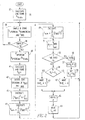
- Figure 2 illustrates a flow chart used by the system to determine the impedance in the bus section 19, and therefore, any change in the impedance of the pressure junction 15.
- any transformer that might be present in the distribution system between the points at which the first and second voltages are measured is taken into account.
- Such a transformer would produce a difference in the upstream and downstream voltages determined by the transformer ratio.
- This transformer ratio could be applied to the voltage samples if known.
- the exemplary system can determine and apply the transformer ratio.
- the transformer in a distribution system will be a step down transformer, in which case, the upstream voltage will be larger than the downstream voltage if a transformer is present.
- the transformer ratio is calculated, by dividing the upstream voltage by the downstream voltage, and stored at 37. If no transformer is present, the ratio will be essentially one.
- a loop is then entered in which V upstream , V downstream and I bus are periodically sampled and stored at 38. In the exemplary system, each of these parameters is measured 28 times per half cycle of the ac power. A selected number of samples, in the example 50, are gathered as indicated at 39. The upstream voltage readings are then adjusted for the transformer ratio at 49. This results in normalization of the impedance readings to the impedance at start up, whether or not there is a transformer present.
- V diff which is the difference between the upstream and the downstream voltage, is calculated and stored at 41.
- V diff and of I bus are located at 43.
- the V diff zero crossing is located by a change of polarity.
- the I bus zero crossing is identified as the sample of current closest to the samples making up the zero crossing of the diff at which the current changes polarity.
- the voltage difference and the current are then squared at 45.
- the voltage differences squared for the 50 samples are then summed at 47 to generate V sum .
- the current squared values for the 50 samples are summed at 49 to generate I sum .
- the 50 samples of the voltage difference and current are counted from the corresponding zero crossings to eliminate the effect of power factor.
- the impedance of the section of the feeder bus, and therefore, essentially across pressure junction 15, is calculated at 51 by dividing V sum by I sum to generate the calculated impedance R c .
- the impedance calculated, R c can be quite noisy, primarily because a small number is being divided by a large number, but also because of jitter caused by slight variations in the timing of the measurements.
- large disturbances are introduced by switching, either in the feeder branch 7 or the balance of plant feeder 9, and by other transients.
- changes in successive values of the impedance output, R are limited to steps equal to the initial calculated value of the impedance, R o , multiplied by a gain, G.
- the impedance R c is calculated as determined at 53 the impedance R output is made equal to the R o at 55.
- the step X by which the impedance R will be permitted to change is then calculated at 57 as the R o multiplied by the gain G.
- the parameter R -1 which represents the last output value for the impedance is made equal to R o at 59.
- the next set of samples are then generated by returning to the sampling loop at 37.
- a determination is made whether the new calculated value of impedance, R c , is greater or smaller than the last output value, R 1 , as determined at 61.
- the impedance output, R is set by adding the step X to the last value of impedance, R 1, at 63 and this new value is output as the impedance R at 65. If the latest calculated value of impedance is less than the previous value, then a negative step, -X, is added to the previous value at 67 and output as the impedance R at 65. In either case, this newly output value of impedance is recorded as the last value at 69 for the next set of samples
- FIG. 3 A computer simulation of the invention was implemented to assess its effectiveness. The results are illustrated in Figures 3 and 4.
- the trace 71 illustrates the instantaneous value of the calculated impedance. This is the value R c calculated at 51 in Figure 2. As can be seen from Figure 3, this instantaneous value has considerable noise due to harmonics. The effects of load switching at 1.5 seconds and 2.5 seconds can also be seen.
- the trace 73 represents the median value produced by the smoothing algorithm and which is output as the impedance R at 65 in Figure 2. Different levels of smoothing can be produced by adjusting the gain G used at 57 in Figure 2.
- Figure 3 also illustrates at 75 an increase in bus impedance to twice the previous value at 3.5 seconds. This increase appears to be four times the previous value in Figure 3 due to the built-in gain in the algorithm (provided by the squaring of sampled values).
- G the smoothing algorithm gain
- G the smoothing algorithm gain, in the example was set to a low value to provide a high level of smoothing, it can be seen that the median value 73 slowly changes to the final value. In the example, this is reached at approximately nine seconds, or 5.5 seconds after the step change in impedance.
- Figure 4 illustrates the simulation of this lack of synchronization of the voltage and current in 13 samples out of 28 in the summed group or a jitter of 49.2 percent.
- the same switching events as in Figure 3 occur at 1.5 seconds and 2.5 seconds, but are overwhelmed in the Figure 4 example by the jitter.
- the median value of impedance output 73 filters out all of this noise while still detecting the step change in impedance at 3.5 seconds.
- FIG. 5 illustrates application of the invention to a practical ac power distribution system 1'.
- This system includes a main bus 77 connected to a source (not shown) providing ac power to a number of feeder buses 79a-79d.
- the feeder bus 79a in turn energizes a number of loads such as motors 81a-81d.
- the motors 81a-81c are each controlled by a motor starter 83 that energizes the motor from the feeder bus 79a.
- Each motor starter includes a circuit breaker 85, a contactor 87 and an overload relay 89, as is well known.
- the fourth motor, 81d is energized by a variable speed drive 91 through another circuit breaker 85.
- Each of the feeder buses 79a through 79d has a circuit breaker 85a through 85d, respectively, adjacent its connection to the main bus 77.
- the main bus 77 has a fuse 93, a main disconnect switch 95, a meter 97, stepdown transformer 99 and a main circuit breaker 85m.
- An additional circuit breaker 85e is included in the feeder bus 79a adjacent the motor starters 83.
- the power distribution system 1' has a number of pressure junctions 103 represented by the solid dots. These pressure junctions 103 include terminals on the various devices, such as for example, the circuit breakers 85, as well as bolted connections 103s at shipping splits in the buses such as bus 79a.
- the meter 97 already includes a voltage tap 105 and a current transformer 107 for performing the metering functions. These voltage and current measurements can be used to perform the impedance monitoring function 109.
- the circuit breakers 85e, 85d and 85m include a current transformer 107 for performing the protection function. They also have a voltage tap 105 or the voltage tap can be added to implement the metering function 109.
- the meter 97 and main breaker 85m are on the ends of a section of the main bus 77 that includes the step-down transformer 99, which has two pressure connections 103 to the meter 97 and the main circuit breaker 101.
- the meter 97 can measure the upstream voltage while the main breaker 85m measures the downstream voltage.
- the current reading from either the meter or main breaker can be used for the current measurement.
- the impedance will be that of the two pressure junctions plus the impedance of the transformer.
- the effect of the transformer can be eliminated by converting the voltage reading taken on the side of the transformer opposite that at which the current reading is taken using the transformer ratio. While this particular arrangement does not identify the particular faulty junction, it narrows the investigation to these two junctions which can then be examined.
- the technique of starting the voltage and current sampling at the zero crossings eliminates the inductive impedance introduced by the transformer.
- Other pressure junctions 103 in the power distribution system 1' can be monitored by other combinations of readings taken with the impedance monitoring function 109 built into the other components. For instance, readings taken by the main breaker 101 and the breaker 85d monitor pressure connections between these two circuit breakers. Similarly, the breaker 85e can cooperate with the main breaker 101 to monitor the group of pressure junctions between them, including the connections to the feeder breaker 85a. Again, a more detailed investigation would have to be conducted to identify the particular pressure junction between these two breakers. It can also be seen that by incorporating the impedance monitoring function 109 into the overload relays 89, that the pressure junctions between the components of the motor starters 83 can be monitored by using the impedance monitoring function built into the circuit breaker 85e.
- the invention permits the impedance of pressure junctions in an ac power distribution system to be monitored on line using the ac power delivered by the power system. No constant dc current source or the filters needed in dc monitoring systems to block the ac power are required.
- the invention can be applied to an existing system utilizing, in many cases, existing voltage and current measuring components.
Landscapes
- Physics & Mathematics (AREA)
- General Physics & Mathematics (AREA)
- Measurement Of Resistance Or Impedance (AREA)
- Supply And Distribution Of Alternating Current (AREA)
- Measurement Of Current Or Voltage (AREA)
- Remote Monitoring And Control Of Power-Distribution Networks (AREA)
- Investigating Or Analyzing Materials By The Use Of Electric Means (AREA)
Abstract
Description
Claims (20)
- A method of determining the impedance across a pressure junction (15) in a section (19) of an energized power distribution system (1) using the energizing power, the method comprising:measuring a first voltage produced by the energizing power at a first end (17) of the section (19) of the energized power system (1);measuring a second voltage produced by the energizing power at a second end (27) of the section (19) of the energized power system (1);measuring current through the section (19) of the energized power system produced by the energizing power; anddetermining the impedance as a difference between first voltage and the second voltage divided by the current.
- The method of Claim 1 wherein the measuring of the first voltage, the second voltage and the current is performed repeatedly multiple times, and wherein determining the impedance of the section (19) of the power distribution system comprises summing a difference between the first and second voltages to generate a summed voltage difference and summing the current to generate a summed current for a selected number of measurements of the first voltage, the second voltage and the current, and dividing the summed voltage difference by the summed current to generate the impedance.
- The method of Claim 2 wherein the energized power distribution system is an ac power distribution system in which the first voltage, second voltage and the current are all ac and wherein the measuring of the first ac voltage, the second ac voltage and the ac current are performed substantially simultaneously.
- The method of Claim 2 wherein determining impedance comprises summing a squared difference between the first voltage and the second voltage to generate a summed voltage difference squared and summing the current squared to generate a summed current squared for the selected number of measurements of the first voltage, the second voltage and the current and dividing the voltage difference squared by the current squared to generate a representation of the impedance.
- The method of Claim 4 wherein the steps of Claim 4 are repeated to generate successive values of the impedance and including limiting changes in the successive values of the impedance.
- The method of Claim 5 wherein limiting changes in successive values of impedance comprises changing the impedance to a preceding value of the impedance plus a value X when the impedance is more than the preceding value of the impedance, and changing the impedance to the preceding value of impedance minus the value X when the impedance is less than the preceding value of the impedance.
- The method of Claim 6 wherein the value X is generated by multiplying a selected gain by an initial value of the impedance.
- The method of Claim 4 wherein the energized power distribution system is an ac power distribution system in which the first voltage, the second voltage and the current are all ac and wherein determining the impedance comprises selecting measurements of the first ac voltage, the second ac voltage and measurements of the ac current used in generating the summed voltage difference squared and the summed current squared to eliminate any power factor in the energizing ac power.
- The method of Claim 8 wherein the selected number of the first ac voltage and the second ac voltage measurements used to generate the summed voltage difference squared and the selected number of ac current measurements used to generate the summed current squared are selected to begin at a zero crossing of the difference between the first and second ac voltage, and a closest zero crossing of the ac current.
- The method of Claim 1 wherein the current is measured by taking two spaced voltage measurements at two spaced apart points not separated by the pressure joint, but through which current through the pressure joint flows and between which a fixed impedance is known, and dividing a difference between the two spaced apart voltage measurements by the known fixed impedance.
- The method of Claim 10 wherein one of the first and second voltage measurements is used as one of the two spaced apart voltage measurements.
- The method of Claim 11 wherein measuring at least one of the first voltage, the second voltage and the current is performed using devices provided in the power distribution system (1) selected from a group comprising: switches, circuit breakers, contactors, network protectors, overcurrent relays and monitors.
- The method of Claim 1 wherein the energized power distribution system is an ac power distribution system energized by ac power such that the first voltage, the second voltage and the current are all ac and wherein measuring the first ac voltage and the second ac voltage comprises calculating a transformer ratio from the first ac voltage and the second ac voltage when the first ac voltage and the second ac voltage differ by a selected amount and applying the transformer ratio to one of the first ac voltage and the second ac voltage before determining the impedance.
- Apparatus for determining the impedance across a pressure junction (15) in a section (19) of an energized power distribution system (1) using the energizing power, the apparatus comprising:first voltage measuring means (21) measuring a first voltage generated by the energizing power at a first end (17) of the section (19) of the energized power distribution system (1);second voltage measuring means (25) measuring a second voltage generated by the energizing power at a second end (27) of the section (19) of the energized power distribution system (1);current measuring means (31) measuring current through the section (19) of the energized power distribution system generated by the energizing power; andmeans determining (35) the impedance by dividing a difference between the first voltage and the second ac voltage by the current.
- The apparatus of Claim 14 wherein the energizing power is ac power so that the first voltage, the second voltage and the current are all ac and the means measuring the first ac voltage (21), the means measuring the second ac voltage (25) and the means measuring the ac current comprise synchronizing means (33) measuring the first ac voltage, the second ac voltage and the ac current substantially simultaneously.
- The apparatus of Claim 14 wherein the means (21) measuring the first voltage, the means (25) measuring the second voltage and the means (31) measuring the current, measure the first voltage, the second voltage and the current repeatedly, and wherein the means (35) determining impedance comprise means (51-69) repetitively calculating the impedance from the selected number of measurements of the first voltage, the second voltage, and the current.
- The apparatus of Claim 14 where the means determining the impedance (35) comprises means (41) repetitively calculating a voltage difference between corresponding measurements of the first and second voltages, means (47) calculating a sum of the difference squared for the selected number of measurements of the first and second voltages, means (49) generating a sum of current squared for the selected number of measurements of the current and means (51) generating successive values of impedance as the sum of the voltage difference squared divided by the sum of the current squared.
- The apparatus of Claim 17 wherein the means determining impedance (35) comprises means (53-69) limiting changes in the successive values of impedance.
- The apparatus of Claim 18 wherein the means (53-69) limiting changes in successive values of impedance comprise means (63) changing the impedance calculated to the preceding value of impedance plus a value X when the impendence is more than the preceding value of the impedance, and means (67) changing the impedance to the preceding value of impedance minus the value X when the impedance is less than the preceding value of impedance.
- The apparatus of Claim 18 wherein the means (53-69) limiting changes in successive values of impedance further comprise means (57) generating the value X as a selected gain times an initial value of the impedance.
Applications Claiming Priority (2)
| Application Number | Priority Date | Filing Date | Title |
|---|---|---|---|
| US10/643,351 US7034554B2 (en) | 2003-08-19 | 2003-08-19 | Method and apparatus for measuring impedance across pressure joints in a power distribution system |
| US643351 | 2003-08-19 |
Publications (2)
| Publication Number | Publication Date |
|---|---|
| EP1508811A2 true EP1508811A2 (en) | 2005-02-23 |
| EP1508811A3 EP1508811A3 (en) | 2005-09-07 |
Family
ID=34063456
Family Applications (1)
| Application Number | Title | Priority Date | Filing Date |
|---|---|---|---|
| EP04018234A Withdrawn EP1508811A3 (en) | 2003-08-19 | 2004-08-02 | Method and apparatus for measuring impedance |
Country Status (6)
| Country | Link |
|---|---|
| US (1) | US7034554B2 (en) |
| EP (1) | EP1508811A3 (en) |
| CN (1) | CN100578235C (en) |
| AU (1) | AU2004203250B2 (en) |
| BR (1) | BRPI0403136A (en) |
| CA (1) | CA2477606C (en) |
Cited By (1)
| Publication number | Priority date | Publication date | Assignee | Title |
|---|---|---|---|---|
| EP1916530A1 (en) * | 2006-10-27 | 2008-04-30 | Helmut-Schmidt-Universität Hamburg | Device and method for measuring the network impedance on the medium voltage level |
Families Citing this family (12)
| Publication number | Priority date | Publication date | Assignee | Title |
|---|---|---|---|---|
| FR3011938B1 (en) * | 2013-10-16 | 2015-12-11 | Schneider Electric Ind Sas | METHOD FOR DETERMINING INDIVIDUAL POWER CONSUMPTION |
| ITUA20163209A1 (en) * | 2016-05-06 | 2017-11-06 | St Microelectronics Srl | CURRENT MEASUREMENT DEVICE IN AN INDUCTIVE LOAD |
| CN108414930B (en) * | 2018-02-11 | 2020-10-20 | 桐城市为诺机器人技术有限公司 | Method for identifying load change of direct current motor based on detection of impedance of direct current motor |
| CN108469546B (en) * | 2018-03-13 | 2020-08-04 | 宁波弘讯科技股份有限公司 | Wire impedance testing method and system |
| CN108387812A (en) * | 2018-03-22 | 2018-08-10 | 北京百度网讯科技有限公司 | Methods, devices and systems for output information |
| EP3948915B1 (en) * | 2019-04-05 | 2026-06-03 | Blixt Tech Ab | Circuit breaker and method for breaking an electrical circuit |
| CN111208351B (en) * | 2020-01-17 | 2022-05-17 | 北京市腾河电子技术有限公司 | Method for calculating power supply line impedance based on load jump and storage medium |
| CN112379195B (en) * | 2020-10-29 | 2023-04-25 | 云南电网有限责任公司 | Secondary circuit detection method for bus protection |
| US12111359B2 (en) * | 2021-12-14 | 2024-10-08 | Eaton Intelligent Power Limited | Method of monitoring joint and contact conditions in an electrical network |
| CN115184679A (en) * | 2022-06-22 | 2022-10-14 | 中冶赛迪工程技术股份有限公司 | Dynamic online detection system and method for high current line impedance of electric arc furnace |
| US12631698B2 (en) | 2023-05-01 | 2026-05-19 | Eaton Intelligent Power Limited | Apparatus, system and method of monitoring joints and switch conditions in an electrical network |
| US20250264506A1 (en) * | 2024-02-20 | 2025-08-21 | Siemens Industry, Inc. | Electric vehicle (ev) charging infrastructure quality predictor |
Family Cites Families (18)
| Publication number | Priority date | Publication date | Assignee | Title |
|---|---|---|---|---|
| US4047104A (en) | 1976-07-28 | 1977-09-06 | Bell Telephone Laboratories, Incorporated | Ohmmeter for circuits carrying unknown currents |
| EP0039751A1 (en) | 1980-05-08 | 1981-11-18 | Imperial Chemical Industries Plc | Electrical resistance measurement |
| US4954782A (en) * | 1987-05-08 | 1990-09-04 | The Boeing Company | Self-checking ohmmeter that checks for contact resistance of its probes |
| GB8800081D0 (en) * | 1988-01-05 | 1988-02-10 | Automated Light Technologies | Resistive fault location means & device for use on electrical cables |
| DE58903408D1 (en) | 1989-02-16 | 1993-03-11 | Mania Gmbh | CIRCUIT FOR MEASURING RESISTORS OF TEST UNITS. |
| US4963830A (en) | 1989-07-19 | 1990-10-16 | Roman Manufacturing, Inc. | Portable impedance meter for resistance welding equipment |
| US5189375A (en) * | 1991-06-04 | 1993-02-23 | United States Of America As Represented By The Secretary Of The Army | Inductive cable resistance tester |
| US5371469A (en) | 1993-02-16 | 1994-12-06 | The United States Of America As Represented By The Administrator Of The National Aeronautics And Space Administration | Constant current loop impedance measuring system that is immune to the effects of parasitic impedances |
| US5365180A (en) | 1993-04-16 | 1994-11-15 | National Semiconductor Corporation | Method for measuring contact resistance |
| US5391991A (en) * | 1993-09-29 | 1995-02-21 | The United States Of America As Represented By The Secretary Of The Army | Cable shield resistance test set |
| JP3468817B2 (en) * | 1994-02-25 | 2003-11-17 | 株式会社東芝 | Field ground fault detector |
| US6281685B1 (en) * | 1995-08-29 | 2001-08-28 | The United States Of America As Represented By The Secretary Of The Army | Cable shield fault locator |
| US5600255A (en) | 1995-11-20 | 1997-02-04 | Electro-Test, Inc. | Live circuit resistance measurement system and method |
| DE19605013C2 (en) * | 1996-01-31 | 1998-04-02 | Siemens Ag | Process for forming a resistance value |
| US6225810B1 (en) * | 1998-02-12 | 2001-05-01 | The Boeing Company | Loop resistance tester (LRT) for cable shield integrity |
| US6477021B1 (en) * | 1998-02-19 | 2002-11-05 | Square D Company | Blocking/inhibiting operation in an arc fault detection system |
| US6160402A (en) | 1998-08-28 | 2000-12-12 | Motorola, Inc. | Method and apparatus for determining contact resistance |
| US6397156B1 (en) * | 1998-11-17 | 2002-05-28 | Abb Inc. | Impedance measurement system for power system transmission lines |
-
2003
- 2003-08-19 US US10/643,351 patent/US7034554B2/en not_active Expired - Lifetime
-
2004
- 2004-07-19 AU AU2004203250A patent/AU2004203250B2/en not_active Ceased
- 2004-08-02 EP EP04018234A patent/EP1508811A3/en not_active Withdrawn
- 2004-08-03 BR BR0403136-9A patent/BRPI0403136A/en not_active Application Discontinuation
- 2004-08-12 CN CN200410056048A patent/CN100578235C/en not_active Expired - Fee Related
- 2004-08-17 CA CA2477606A patent/CA2477606C/en not_active Expired - Fee Related
Cited By (1)
| Publication number | Priority date | Publication date | Assignee | Title |
|---|---|---|---|---|
| EP1916530A1 (en) * | 2006-10-27 | 2008-04-30 | Helmut-Schmidt-Universität Hamburg | Device and method for measuring the network impedance on the medium voltage level |
Also Published As
| Publication number | Publication date |
|---|---|
| EP1508811A3 (en) | 2005-09-07 |
| AU2004203250B2 (en) | 2008-10-09 |
| BRPI0403136A (en) | 2005-04-05 |
| AU2004203250A1 (en) | 2005-03-10 |
| CA2477606C (en) | 2013-11-19 |
| CN100578235C (en) | 2010-01-06 |
| CN1584609A (en) | 2005-02-23 |
| CA2477606A1 (en) | 2005-02-19 |
| US20050040835A1 (en) | 2005-02-24 |
| US7034554B2 (en) | 2006-04-25 |
Similar Documents
| Publication | Publication Date | Title |
|---|---|---|
| US7034554B2 (en) | Method and apparatus for measuring impedance across pressure joints in a power distribution system | |
| CN100431232C (en) | State Estimation of Power Transmission Network | |
| JP7535984B2 (en) | Method and apparatus for estimating source impedance in one or more transmission lines - Patents.com | |
| JP5618758B2 (en) | Method and system for monitoring short-circuit capacity of power system | |
| AU2022377184B2 (en) | Improved accuracy for phasor measurement units (synchrophasors) in utility distribution applications | |
| CN119125782B (en) | A method, device and system for locating faults in medium-voltage lines | |
| CN115336130A (en) | Fault detection in power transmission systems | |
| Abdul-Malek | A new method to extract the resistive component of the metal oxide surge arrester leakage current | |
| RU2351048C1 (en) | Method of functional diagnostics for induction motors | |
| JP7585722B2 (en) | Insulation Resistance Monitoring Device | |
| CN111289837A (en) | A method and system for evaluating latent faults of distribution network equipment | |
| EP3770615B1 (en) | Electrical network impedance determination | |
| Bayati et al. | A high-impedance fault detection scheme for DC aircrafts based on comb filter and second derivative of voltage | |
| CN121596022A (en) | System and method for monitoring a power distribution system | |
| JP4527346B2 (en) | Insulation state monitoring method and device | |
| CN109655681A (en) | A kind of substation and switchyard double measurement circuit method for detecting abnormality and system | |
| US20040130327A1 (en) | Ground circuit impedance measurement apparatus and method | |
| Geiger et al. | Flicker limit compliance assessment in the presence of background disturbances | |
| US11965916B2 (en) | Method and device for determining the resistive component of the leakage current impedance in the alternating current network | |
| CN111060759A (en) | Power distribution cabinet test system and test method | |
| RU2028634C1 (en) | Method of and device for insulation resistance measurement in alternating-current lines incorporating static converters | |
| KR101779706B1 (en) | Detecting method of fault current in power system | |
| JP3829529B2 (en) | Peak cut controller | |
| Stojčić et al. | Detecting high-resistance connection asymmetries in inverter fed AC drive systems | |
| CN112595903B (en) | Single-phase ammeter phase judgment method, device and meter reading system |
Legal Events
| Date | Code | Title | Description |
|---|---|---|---|
| PUAI | Public reference made under article 153(3) epc to a published international application that has entered the european phase |
Free format text: ORIGINAL CODE: 0009012 |
|
| AK | Designated contracting states |
Kind code of ref document: A2 Designated state(s): AT BE BG CH CY CZ DE DK EE ES FI FR GB GR HU IE IT LI LU MC NL PL PT RO SE SI SK TR |
|
| AX | Request for extension of the european patent |
Extension state: AL HR LT LV MK |
|
| PUAL | Search report despatched |
Free format text: ORIGINAL CODE: 0009013 |
|
| AK | Designated contracting states |
Kind code of ref document: A3 Designated state(s): AT BE BG CH CY CZ DE DK EE ES FI FR GB GR HU IE IT LI LU MC NL PL PT RO SE SI SK TR |
|
| AX | Request for extension of the european patent |
Extension state: AL HR LT LV MK |
|
| RIC1 | Information provided on ipc code assigned before grant |
Ipc: 7G 01R 27/08 B Ipc: 7G 01N 27/00 B Ipc: 7G 01R 27/00 A |
|
| AKX | Designation fees paid | ||
| STAA | Information on the status of an ep patent application or granted ep patent |
Free format text: STATUS: THE APPLICATION IS DEEMED TO BE WITHDRAWN |
|
| 18D | Application deemed to be withdrawn |
Effective date: 20050824 |
|
| REG | Reference to a national code |
Ref country code: DE Ref legal event code: 8566 |