EP1508800A1 - Detecting unit for x-ray diffraction measurements - Google Patents
Detecting unit for x-ray diffraction measurements Download PDFInfo
- Publication number
- EP1508800A1 EP1508800A1 EP04013353A EP04013353A EP1508800A1 EP 1508800 A1 EP1508800 A1 EP 1508800A1 EP 04013353 A EP04013353 A EP 04013353A EP 04013353 A EP04013353 A EP 04013353A EP 1508800 A1 EP1508800 A1 EP 1508800A1
- Authority
- EP
- European Patent Office
- Prior art keywords
- collimating system
- detecting unit
- tubular channels
- unit according
- collimating
- Prior art date
- Legal status (The legal status is an assumption and is not a legal conclusion. Google has not performed a legal analysis and makes no representation as to the accuracy of the status listed.)
- Granted
Links
Images






Classifications
-
- G—PHYSICS
- G01—MEASURING; TESTING
- G01N—INVESTIGATING OR ANALYSING MATERIALS BY DETERMINING THEIR CHEMICAL OR PHYSICAL PROPERTIES
- G01N23/00—Investigating or analysing materials by the use of wave or particle radiation, e.g. X-rays or neutrons, not covered by groups G01N3/00 – G01N17/00, G01N21/00 or G01N22/00
- G01N23/20—Investigating or analysing materials by the use of wave or particle radiation, e.g. X-rays or neutrons, not covered by groups G01N3/00 – G01N17/00, G01N21/00 or G01N22/00 by using diffraction of the radiation by the materials, e.g. for investigating crystal structure; by using scattering of the radiation by the materials, e.g. for investigating non-crystalline materials; by using reflection of the radiation by the materials
- G01N23/20008—Constructional details of analysers, e.g. characterised by X-ray source, detector or optical system; Accessories therefor; Preparing specimens therefor
Definitions
- the invention relates to means used in conducting X-ray diffraction measurements, in particular, those belonging to X-ray diffractometers, namely, to a detecting unit.
- a detecting unit which comprises detector and Soller slit system in the form of assembly of thin plates parallel to a plane, is comprised the primary X-ray beam and the normal to surface of the sample studied, that also passing through center of goniometer (see D.A. Goganov, B.S. Losinsky, N.B. Tsvetova, T.P. Toporkova. Sealed-off proportional X-ray emission counter SPRO-12. - In: Apparatura i metody rentgenovskogo sau (Equipment and methods for X-ray analysis). Leningrad, Mashinostroenie editing house, 1972, Issue 11, pp.151-155 [1] (in Russian)).
- This detecting unit also comprises a collimating slit, located in a plane perpendicular to that specified and carrying a beam of X-rays reflected by the sample studied.
- the largest dimension of irradiated area of the sample studied lies in the plane passing through collimating slit in parallel with its generatrices, and the smallest one - in the plane perpendicular to collimating slit.
- This detecting unit utilized in X-ray diffractometric photography with focusing schemes, captures only narrow beam of X-rays reflected by the sample studied. In real measurements, this angle is of an order of several angular minutes. In order to obtain information with such detecting unit in angular range of several tens of degrees, it is necessary to perform exposure several hundred times. Total exposure time will increase correspondingly.
- This detecting unit comprises straight or curved position-sensitive detector and a slit situated along detector window (see Ortendahl D., Perez-Mendez V., Stoker J. One dimensional curved wire chamber for powder X-ray crystallography. - Nucl. Instrum. and Meth., 1978, Vol.156, No.1-2, p.53-56, [2]).
- this detecting unit Due to the fact of this detecting unit have the detector extended along diffraction angle, in case of its utilization in the above scheme of measurements; the information is obtained simultaneously for a certain range of reflection angles ⁇ .
- collimating system such as represented by said slit
- collimating system is narrows considerably the detector window in the plane perpendicular to the diffraction angle, thus lead to reducing reflected radiation intensity being detected.
- the collimation is completely absent in the plane of the diffraction angle.
- any reflected X-rays, incident on detector are captured, resulting in distortion of the diffractogram obtained.
- the invention proposed is directed to achievement of technical results involving the prevention of distortion in the diffractograms obtained and also increase the detecting unit sensitivity.
- the technical substance of the detecting unit proposed and by description of its particular embodiments, other kinds of technical result achieved will be identified as well.
- the proposed detecting unit for X-ray diffraction measurements similar to that most close, known from [2], comprises position-sensitive detector and collimating system located in front of its window.
- collimating system in the detecting unit is made in the form of honeycomb structure, comprising multitude of tubular channels for conveying the diffracted X-ray radiation.
- the walls of adjacent tubular channels are fused together.
- Tubular channels, forming outlet end face of collimating system are oriented with their outlet ends, towards window of the position-sensitive detector, and are made converging towards inlet end face of the collimating system.
- outlets of tubular channels in the outlet end face of collimating system are arranged in several rows along window of the position-sensitive detector. Walls of the tubular channels are made of material capable to absorb X-ray radiation, or have a coating of such material.
- tubular channels may have the shape of a truncated cone or pyramid.
- An embodiment of the proposed detecting unit is possible, in which case of the greatest transverse dimension D of a separate tubular channel of the collimating system and its length H are satisfied relationship: D / H > ⁇ c , where ⁇ c denotes critical angle of total external reflection of X-ray radiation from channel walls material. Fulfilment of this condition prevents possibility of transmittance to the channel outlet of rays, having at the tubular channel inlet a deviation from its longitudinal axis below ⁇ c , due to multiple total external reflections.
- the detecting unit may be structured with collimating system having outlet end face in the form of cylindrical surface, with tubular channels oriented by radii of this cylindrical surface.
- the inlet end face of collimating system of the detecting unit proposed may also have a shape of cylindrical surface, coaxial with that specified above.
- the collimating system of the detecting unit may be constructured also with planar or parallel to one another surfaces of outlet or inlet end faces and longitudinal axes of tubular channels having extensions intersecting in a point, laying on the perpendicular to said planar surfaces, and passing through geometrical center of outlet or inlet end faces.
- collimating system may be executed with planar surfaces of outlet and inlet end faces, situated in parallel one to another, and longitudinal axes of tubular channels oriented by radii of coaxial cylindrical surfaces, having common axis perpendicular to said planar surfaces.
- the tubular channels may be formed using glass mono- or polycapillaries.
- their walls may be made, in particular, from lead glass.
- Walls of the tubular channels, formed by glass mono- or polycapillaries, may have a coating of lead or other heavy metal.
- Collimating system of the detecting unit proposed is installed with possibility of adjusting its position relative to window of the position-sensitive detector. Changes in distance or orientation of the collimating system in respect to detector window allow to adjust position of focus (a point of intersection, or line segment intersecting with extensions of longitudinal axes of the tubular channels of collimating system in the embodiments described above) relative to surface of the sample studied, as well as to display interference pattern of diffraction in a form typical for different methods of its capture. This, in its turn, provides possibility to compare diffractograms obtained with those containing in different databases collected in X-ray diffraction pictures.
- collimating system may be installed with possibility of linear displacement in the direction of longitudinal axis of one of its tubular channels, situated in central zone of the collimating system.
- Collimating system may be installed also with possibility of rotation about axis, perpendicular to a plane passing through the middle one of tubular channels rows having outlets situated in the outlet end face of the collimating system.
- Proposed detecting unit for X-ray diffraction measurements comprises following elements (Fig. 1a and b):
- Collimating system 2 is made in the form of honeycomb structure (Fig. 2) comprising multitude of tubular channels for transmittance of diffracted X-ray radiation. Walls of adjacent tubular channels 16 are fused together.
- a dimension of the window of position-sensitive detector 1 in transverse direction is small in comparison with its length, then it is possible to build collimating system 2 with outlet end face 22 and inlet end face 23 in the form of coaxial cylindrical surfaces (Fig. 3a). At that, dimension of outlet end face 22 is close to that of window of the position-sensitive detector.
- Tubular channels 16 in this case are oriented by radii of said cylindrical surfaces, and collimating system has a linear focus 24 situated on common axis of these surfaces.
- collimating system comprising detecting unit having point focus, with outlet and inlet end faces in the form of concentric spherical surfaces (Fig. 3b), and longitudinal axes of tubular channels oriented by radii of this spherical surface and their extensions intersecting in focus 24.
- one or both of its end faces may be planar, as shown in Fig. 3c, which depicts planar and parallel to one another outlet 22 and inlet 23 end faces.
- Such collimating system may be represented as kind of "truncated" collimating system with cylindrical or spherical end faces.
- Tubular channels have rectilinear longitudinal axes and converge towards inlet end face 22 of the collimating system.
- they are shaped as truncated cone or pyramid, with lesser bases forming inlet end face of collimating system. At that, said cone does not have to be circular, and pyramid - a regular one.
- Tubular channels are oriented with their outlet ends, forming outlet end face 22 of collimating system, towards window 19 of the position-sensitive detector (Fig. 1).
- Outlets of tubular channels in the outlet end face 22 of collimating system 2 are arranged in several rows, oriented along window 19 of the position-sensitive detector 1. Number of said rows determines dimension of collimating system in transverse direction and depends on the window width of the position-sensitive detector 1. It should be such as to ensure the uttermost utilization of window area of the position-sensitive detector.
- Collimating system in the form of said honeycomb structure having required configuration may be made, in particular, of glass, by using technology for polycapillary structures production, similar to that disclosed in patent of Russian Federation No.2096353, publ. 20.11.97 [3].
- glass tubes or glass capillaries or polycapillaries made of lead glass, or those having internal walls coating made of lead or other heavy metal absorbing X-ray radiation may be used as source material in realization of said technology.
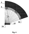
- Fig. 4 which illustrates the case of focus 24 of the collimating system being situated inside the specimen studied 15, in what manner occurs “screening” of "extraneous" rays in the plane of diffraction angle. Such a ray, crossed-out in the drawing, will not enter any of tubular channels 16 and, therefore, may not cause distortion of the diffractogram obtained.
- X-ray tube 12 (Fig. 5) and X-ray half-lens 13 generate parallel primary X-ray beam 14.
- This beam being reflected in specimen 15 studied from unlike crystallographic planes hkl and HKL having normals N1 and N2, at angles ⁇ 1 and ⁇ 2, correspondingly, gives rise to diffracted X-ray beams from the planes hkl and HKL.
- Diffracted beams on coming selectively through collimating system 2, are registered with position-sensitive detector 1.
- the X-ray tube 12 and X-ray half-lens 13 are placed and fastened securely at an angle of 45° to the surface of specimen studied 15, or at other angle, determined by the purpose of investigations, depending on the anode material of X-ray tube 12.
- the specimen studied 15 is positioned for X-ray phase analysis in such a way as to place the largest possible portion of its surface in reflecting position. To do this, in particular, rotation is used of the specimen studied 15 around axis perpendicular to its surface (see: Portable Parallel Beam X-ray Diffraction System ⁇ / ⁇ Diffractometer, STOE News, STOE&CIE, 2003, S.1-28, [4]).
- X-ray tube 12 with half-lens 13 is positioned for measurements in the range of large diffraction angles ⁇ in such a way that beam 14 would be incident at an angle of 60° to 80° to the surface of the specimen 15 studied (see: S.S.Gorelik, Yu.A.Skakov, L.N.Rastorguev, Rentgenovskiy i elektronno-opticheskiy analiz (X-ray and electron-optical analysis), Moscow, MISIS, "Nauka” publishers, 2002, p.17-122 [6] (in Russian)).
- X-ray tube 12 with half-lens 13 is positioned for shaping of beam 14 at an angle of 45° to the surface of specimen studied 15.
- Each of m regions of coherent scattering reflects narrow parallel X-ray beam (having greater divergence than that incident, because region of coherent scattering itself is a selector of radiation with different wavelength, and primary beam carries ⁇ - and ⁇ - components of K-series of characteristic X-ray radiation) at an angle, corresponding to interplanar distances of planes, reflecting in the given region of coherent scattering.
- irradiated area has finite geometrical dimensions
- the detecting unit proposed solves following problems:
- Fig. 6 shows position of the collimating system 2 focused on surface of the specimen studied 15.
- Outlet window 22 of the collimating system has equal distances 17 and 18 to the detector 1.
- Axes of tubular channels of the collimating system 2 converge in a point focus 24 on surface of the specimen studied 15.
- tungsten carbide In order to provide comparative performance evaluation of the detecting unit proposed and that known from [2], diffractograms of tungsten carbide (WC) have been registered, which are demonstrated in Fig. 7.
- Diffractogram shown in Fig. 7a represents a diffraction pattern registered using the detecting unit of a design known from [2], and diffractogram in Fig. 7b - that using the detecting unit proposed.
- perceptible effects include lowering of background level, decrease in the width of X-ray interference peaks and resolution increase ("peak-background" ratio).
- partial filtration takes place of ⁇ -component of the primary X-ray beam radiation 14.
- Fig. 8 By varying the position of collimating system 2 and its orientation angles relative to detector 1, selective transmission may be achieved (Fig. 8) of ⁇ - and ⁇ -components of the primary X-ray beam.
- focus 24 of tubular channels of the collimating system 2 moves below the surface of the specimen studied 15. Regions of coherent scattering themselves divide ⁇ - and ⁇ -components of the primary parallel beam 14 by their reflection angle.
- an angle range By moving the collimating system 2 from position 2.1 into position 2.2, an angle range may be passed over, in which either both ⁇ - and ⁇ -components of diffracted beam will be transmitted to the outlet of collimating system (variant "a" at the bottom of Fig. 8), or only ⁇ -component (variant "b") or only ⁇ -component (variant "c”). It is impossible to achieve this in the primary beam with no collimating systems whatever, except for diffraction (use of monochromators).
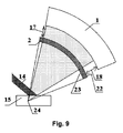
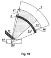
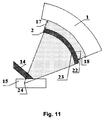
- Fig. 9 shows displacement of the collimating system 2 along the axis of one of its central tubular channels while keeping equal changes in distances 17 and 18 to the position-sensitive detector 1.
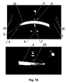
- Maximum transmittance of X-rays by collimating system 2 is achieved by rotation of the collimating system about axis 11 lying in a plane passing through the middle one of tubular channels rows, and perpendicular to central tubular channel in said row (Fig. 14), so as to increase as much as possible capture angle ⁇ of diffracted radiation with full width of window 19 of the position-sensitive detector 1 in ⁇ 2 ⁇ ) range of detection angles.
- Possibility to place different angular ranges of the interference pattern in unequal conditions in one exposure allows comparing X-ray pictures containing in different, by conditions of their registration, databases. To this end, it is enough preliminarily to calibrate the collimating system by reference substance.
- simulating diffraction pattern of interference obtained using Debye chambers, with " ⁇ -2 ⁇ "-diffractometers having different focusing arrangements and " ⁇ - ⁇ "-diffractometers by parallel beam method, all databases accumulated in X-ray crystallography may be used.
- Two-coordinate position-sensitive detectors are employed to an increasing extent in X-ray diffractometry, especially in those fields where due to the complex structure of the object investigated use of single-coordinate detectors is associated with multiple exposure (see: V. Kahenberg, C.S.J.Shaw and J.B. Parrise. Crystal structure analysis of sinthetic Ca 4 Fe 1,5 Al 17,67 O 32 : A high-pressure, spinel-related phase, American Mineralogist, Vol.86, pp.1477-1482, 2001 [8]).
- Two-coordinate position-sensitive detector may also be used in the detecting unit proposed, furnished with collimating system in the form of specified honeycomb structure, located in front of the window of position-sensitive detector.
Landscapes
- Chemical & Material Sciences (AREA)
- Crystallography & Structural Chemistry (AREA)
- Physics & Mathematics (AREA)
- Health & Medical Sciences (AREA)
- Life Sciences & Earth Sciences (AREA)
- Analytical Chemistry (AREA)
- Biochemistry (AREA)
- General Health & Medical Sciences (AREA)
- General Physics & Mathematics (AREA)
- Immunology (AREA)
- Pathology (AREA)
- Analysing Materials By The Use Of Radiation (AREA)
Abstract
Description
- position-
sensitive detector 1; - collimating system 2 (shown only in Fig. 1 a), rigidly mounted on rocker 5 (see below);
- mounting
plate 3 for sliding joint with position-sensitive detector 1 in slotted guides 10 by means ofmechanism 9 and arrangement of other mechanisms on said plate; -
mechanism 4 for rotation of collimatingsystem 2 aboutaxis 7 perpendicular to a plane passing through the middle one of tubular channels rows having outlets situated in the outlet end face of collimating system; -
rocker 5, used for mounting of the collimating system in mechanism for its rotation around axis perpendicular to a plane passing through the middle one of tubular channels rows having outlets situated in the outlet end face of collimating system, and for rotation of said mechanism itself about axis lying in a plane passing through the middle one of tubular channels rows, perpendicular to the central tubular channel in said row; -
frame 6 for mounting ofaxis 7 on mountingplate 3; -
axis 7 ofcollimating system 2 rotation, said axis being perpendicular to a plane passing through the middle one of tubular channels rows having outlets situated in the outlet end face 22 ofcollimating system 2; -
mechanism 8 for rotation of collimatingsystem 2 around imaginary axis lying in a plane passing through the middle one of tubular channels rows having outlets situated in the outlet end face of collimating system, said axis being perpendicular to the central tubular channel in the middle of row; -
mechanism 9 for distance changing betweencollimating system 2 andwindow 19 of position-sensitive detector 1; - guide
slots 10 in mountingplate 3 for parallel displacement ofcollimating system 2 relative towindow 19 of position-sensitive detector 1.
D/H> c .
c = ℎωp /E,
where D and H denote, correspondingly, the largest transverse dimension of a separate tubular channel and its length,
c is a critical angle of total external reflection of X-ray radiation from channel walls material,
ℎ is Planck constant,
ω p denotes plasma frequency of the material of tubular channels walls, and
E denotes quantum energy of X-ray radiation used,
than due to multiple total external reflection, a possibility is excluded of transmission to the channel's end of rays having at the inlet of the tubular channel a deviation from its longitudinal axis, not exceeding c .
- transmittance and registration of all X-rays, passing in axial direction of tubular channels, from as large irradiated area as possible, utilizing greatest possible area of detector window without its being overlapped with a slit;
- interception of all other secondary X-rays, whether reflected or those generated due to fluorescence, on their way to the window of position-sensitive detector;
- removal of the requirement, mandatory in schemes [4]-[5], as to monochromatization of primary X-ray beam, which decrease intensity of the primary beam by 12-15 times;
- increase in radiation intensity captured by the position-sensitive detector and provision of additional instrument for researcher in the form of second wavelength (energy space between Kα-radiation and Kβ-radiation are known for all metals employed as anodes in X-ray tubes), which is so often missing with monochromatization of the primary beam.
- registration of X-ray radiation obtained from larger irradiated area of the specimen studied and maximum utilization of window area of the position-sensitive detector;
- interception of all "extraneous" secondary X-rays, whether reflected or generated due to fluorescence, on their way to the window of position-sensitive detector;
- elimination of the necessity in monochromatization of primary beam and consequent increase in the intensity of radiation acting on position-sensitive detector;
- realization of possibilities, provided by use of second wavelength, which are absent in case of monochromatization of the primary beam;
- adjustment of resolving power of diffractogram in desired region of the diffraction angles range studied;
- acquisition of diffractograms, suitable for comparison with those taken from different databases created in roentgenography.
Claims (15)
- Detecting unit for X-ray diffraction measurements, comprising position-sensitive detector and collimating system, located on front of its window, characterized in that said collimating system is made in the form of honeycomb structure comprising multitude of tubular channels for transmittance of diffracted X-ray radiation, walls of adjacent tubular channels being fused together, tubular channels being made converging towards inlet end face of said collimating system and oriented with their outlet ends, forming outlet end face of said collimating system, towards window of said position-sensitive detector, the outlets of tubular channels in said outlet end face of said collimating system being arranged in several rows along window of said position-sensitive detector, said walls of tubular channels baing made of the material, absorbing X-ray radiation, or have a coating of such material, and collimating system furthermore being installed with possibility of adjusting its position relative to the window of said position-sensitive detector.
- Detecting unit according to claim 1, characterized in that the collimating system is made with outlet end face in the form of cylindrical surface, tubular channels being oriented by radii of said cylindrical surface.
- Detecting unit according to claim 2, characterized in that the inlet end face of said collimating system has a form of cylindrical surface, coaxial with that specified.
- Detecting unit according to claim 1, characterized in that the collimating system is made with outlet end face in the form of spherical surface, tubular channels having longitudinal axes oriented by radii of said spherical surface.
- Detecting unit according to claim 4, characterized in that the inlet end face of said collimating system has a form of spherical surface, concentric with that specified.
- Detecting unit according to claim 1, characterized in that the collimating system is made with planar and parallel to one another surfaces of said outlet and inlet end faces, extensions of longitudinal axes of said tubular channels intersecting in a point lying on a perpendicular to said planar surfaces, passing through geometrical center of said outlet or inlet end faces.
- Detecting unit according to claim 1, characterized in that the collimating system is made with planar, parallel to one another surfaces of outlet and inlet end faces, longitudinal axes of tubular channels being oriented by radii of said coaxial cylindrical surfaces.
- Detecting unit according to any of claims 1 to 7, characterized in that the collimating system is installed with possibility of linear displacement in the direction of longitudinal axis of one of said tubular channels, situated in central zone of collimating system.
- Detecting unit according to any of claims 1 to 7, characterized in that the collimating system is installed with possibility of rotation about axis perpendicular to a plane passing through the middle one of tubular channels rows.
- Detecting unit according to any of claims 1 to 7, characterized in that the collimating system is installed with possibility of rotation around axis lying in a plane passing through the middle one of tubular channels rows, and normal to central tubular channel in said row.
- Detecting unit according to claim 10, characterized in that the collimating system is installed with the possibility of rotation around axis perpendicular to a plane passing through the middle one of tubular channels rows.
- Detecting unit according to claim 8, characterized in that the collimating system is installed with rotation possibility around axis perpendicular to a plane passing through the middle one of tubular channels rows.
- Detecting unit according to claim 8, characterized in that the collimating system is installed with the possibility of rotation around axis lying in a plane passing through the middle one of tubular channels rows, and perpendicular to central tubular channel in said row.
- Detecting unit according to claim 12, characterized in that the collimating system is installed with possibility of rotation about axis perpendicular to a plane passing through the middle one of tubular channels rows.
- Detecting unit according to any of claims 1 to 7, and 11 to 14, characterized in that the greatest transverse dimension D of a separate tubular channel and its length H satisfy relationship: D/H>c, where c denotes critical angle of total external reflection of X-ray radiation from material of channel walls.
Applications Claiming Priority (2)
| Application Number | Priority Date | Filing Date | Title |
|---|---|---|---|
| RU2003125341/28A RU2242748C1 (en) | 2003-08-19 | 2003-08-19 | Detecting assembly for x-ray diffraction measurements |
| RU2003125341 | 2003-08-19 |
Publications (2)
| Publication Number | Publication Date |
|---|---|
| EP1508800A1 true EP1508800A1 (en) | 2005-02-23 |
| EP1508800B1 EP1508800B1 (en) | 2008-02-27 |
Family
ID=34057076
Family Applications (1)
| Application Number | Title | Priority Date | Filing Date |
|---|---|---|---|
| EP04013353A Expired - Lifetime EP1508800B1 (en) | 2003-08-19 | 2004-06-07 | Detecting unit for x-ray diffraction measurements |
Country Status (5)
| Country | Link |
|---|---|
| US (1) | US7149279B2 (en) |
| EP (1) | EP1508800B1 (en) |
| CN (1) | CN1590992A (en) |
| DE (1) | DE602004012031T2 (en) |
| RU (1) | RU2242748C1 (en) |
Cited By (1)
| Publication number | Priority date | Publication date | Assignee | Title |
|---|---|---|---|---|
| WO2008097345A3 (en) * | 2006-08-10 | 2008-12-24 | X Ray Optical Sys Inc | Wide parallel beam diffraction imaging method and system |
Families Citing this family (11)
| Publication number | Priority date | Publication date | Assignee | Title |
|---|---|---|---|---|
| US7231017B2 (en) * | 2005-07-27 | 2007-06-12 | Physical Optics Corporation | Lobster eye X-ray imaging system and method of fabrication thereof |
| US20100329424A1 (en) * | 2009-06-30 | 2010-12-30 | Geoffrey Harding | X-ray diffraction imaging system and method for operating the same |
| KR101239765B1 (en) * | 2011-02-09 | 2013-03-06 | 삼성전자주식회사 | X-ray generating apparatus and x-ray imaging system having the same |
| GB2496484B (en) | 2011-11-11 | 2016-04-06 | Rigaku Denki Co Ltd | X-Ray intensity correction method and x-ray diffractometer |
| JP5492173B2 (en) * | 2011-11-11 | 2014-05-14 | 株式会社リガク | Diffraction X-ray detection method and X-ray diffraction apparatus |
| JP5695589B2 (en) * | 2012-03-02 | 2015-04-08 | 株式会社リガク | X-ray intensity correction method and X-ray diffraction apparatus |
| US9939393B2 (en) | 2015-09-28 | 2018-04-10 | United Technologies Corporation | Detection of crystallographic properties in aerospace components |
| JP6155538B2 (en) * | 2015-11-30 | 2017-07-05 | パルステック工業株式会社 | X-ray diffraction measurement apparatus and X-ray diffraction measurement method |
| DE102017223228B3 (en) | 2017-12-19 | 2018-12-27 | Bruker Axs Gmbh | Setup for spatially resolved measurement with a wavelength-dispersive X-ray spectrometer |
| CN109374660B (en) * | 2018-11-22 | 2024-09-06 | 北京科技大学 | Apparatus for high-throughput powder diffraction with a pencil beam |
| CN115524350B (en) * | 2021-06-25 | 2026-03-06 | 中国兵器工业第五九研究所 | A receiving collimator for a diffraction measurement device |
Citations (3)
| Publication number | Priority date | Publication date | Assignee | Title |
|---|---|---|---|---|
| US2635192A (en) * | 1949-10-24 | 1953-04-14 | Babcock & Wilcox Co | Fluorescent spectral analysis |
| US3154684A (en) * | 1960-06-22 | 1964-10-27 | Lab For Electronics Inc | X-ray analysis system with means to detect only the coherently scattered X-rays |
| US5394453A (en) * | 1992-02-06 | 1995-02-28 | U.S. Philips Corporation | Device for measuring the pulse transfer spectrum of elastically scattered X-ray quanta |
Family Cites Families (19)
| Publication number | Priority date | Publication date | Assignee | Title |
|---|---|---|---|---|
| AT346629B (en) * | 1972-01-28 | 1978-11-27 | Efanov Valery P | PROCESS FOR ROENTGEN DIFFraction TOPOGRAPHING OF SINGLE CRYSTALS AND DEVICE FOR IMPLEMENTING THESE |
| US4495636A (en) * | 1981-01-02 | 1985-01-22 | Research Corporation | Multichannel radiography employing scattered radiation |
| US4519092A (en) * | 1982-10-27 | 1985-05-21 | Albert Richard D | Scanning x-ray spectrometry method and apparatus |
| US4958081A (en) * | 1985-08-14 | 1990-09-18 | Siemens Gammasonics, Inc. | Focusing collimator and method for making it |
| US5007072A (en) * | 1988-08-03 | 1991-04-09 | Ion Track Instruments | X-ray diffraction inspection system |
| DE4034602A1 (en) * | 1990-06-20 | 1992-05-07 | Philips Patentverwaltung | ARRANGEMENT FOR MEASURING THE IMPULSE TRANSMISSION SPECTRUM OF ROENTGEN QUANTS |
| US5373544A (en) * | 1992-08-12 | 1994-12-13 | Siemens Aktiengesellschaft | X-ray diffractometer |
| RU2072515C1 (en) * | 1993-01-26 | 1997-01-27 | Акционерное общество "Элскорт" | Multichannel x-ray element composition analyzer |
| EP0617431B1 (en) * | 1993-03-25 | 1997-05-14 | Seiko Instruments Inc. | X-ray analysing apparatus |
| RU2096353C1 (en) | 1994-02-28 | 1997-11-20 | Мурадин Абубекирович Кумахов | Method of manufacturing multiple-capillary rigid fiber-optic structure or element and device for controlling x-ray and other emissions |
| DE69427152T2 (en) * | 1994-07-08 | 2001-11-22 | Muradin Abubekirovic Kumachov | METHOD FOR GUIDING NEUTRAL AND CARGO BEAMS AND A DEVICE FOR IMPLEMENTING THE METHOD |
| US5727044A (en) * | 1994-07-19 | 1998-03-10 | University Of Leicester | Microchannel plates |
| US5747821A (en) * | 1995-08-04 | 1998-05-05 | X-Ray Optical Systems, Inc. | Radiation focusing monocapillary with constant inner dimension region and varying inner dimension region |
| CN1069136C (en) * | 1996-02-17 | 2001-08-01 | 北京师范大学 | Integral X-ray lens and manufacturing method thereof and equipment using the same |
| US5778039A (en) * | 1996-02-21 | 1998-07-07 | Advanced Micro Devices, Inc. | Method and apparatus for the detection of light elements on the surface of a semiconductor substrate using x-ray fluorescence (XRF) |
| US5933473A (en) * | 1996-04-04 | 1999-08-03 | Hitachi, Ltd. | Non-destructive inspection apparatus and inspection system using it |
| US6069934A (en) * | 1998-04-07 | 2000-05-30 | Osmic, Inc. | X-ray diffractometer with adjustable image distance |
| DE19954663B4 (en) * | 1999-11-13 | 2006-06-08 | Smiths Heimann Gmbh | Method and device for determining a material of a detected object |
| RU2180439C2 (en) * | 2000-02-11 | 2002-03-10 | Кумахов Мурадин Абубекирович | Process of generation of image of internal structure of object with use of x-rays and device for its realization |
-
2003
- 2003-08-19 RU RU2003125341/28A patent/RU2242748C1/en not_active IP Right Cessation
-
2004
- 2004-06-07 DE DE602004012031T patent/DE602004012031T2/en not_active Expired - Fee Related
- 2004-06-07 EP EP04013353A patent/EP1508800B1/en not_active Expired - Lifetime
- 2004-06-14 US US10/865,939 patent/US7149279B2/en not_active Expired - Fee Related
- 2004-08-10 CN CNA2004100567206A patent/CN1590992A/en active Pending
Patent Citations (3)
| Publication number | Priority date | Publication date | Assignee | Title |
|---|---|---|---|---|
| US2635192A (en) * | 1949-10-24 | 1953-04-14 | Babcock & Wilcox Co | Fluorescent spectral analysis |
| US3154684A (en) * | 1960-06-22 | 1964-10-27 | Lab For Electronics Inc | X-ray analysis system with means to detect only the coherently scattered X-rays |
| US5394453A (en) * | 1992-02-06 | 1995-02-28 | U.S. Philips Corporation | Device for measuring the pulse transfer spectrum of elastically scattered X-ray quanta |
Cited By (1)
| Publication number | Priority date | Publication date | Assignee | Title |
|---|---|---|---|---|
| WO2008097345A3 (en) * | 2006-08-10 | 2008-12-24 | X Ray Optical Sys Inc | Wide parallel beam diffraction imaging method and system |
Also Published As
| Publication number | Publication date |
|---|---|
| CN1590992A (en) | 2005-03-09 |
| RU2242748C1 (en) | 2004-12-20 |
| RU2003125341A (en) | 2005-02-20 |
| EP1508800B1 (en) | 2008-02-27 |
| US20050041776A1 (en) | 2005-02-24 |
| US7149279B2 (en) | 2006-12-12 |
| DE602004012031D1 (en) | 2008-04-10 |
| DE602004012031T2 (en) | 2009-03-19 |
Similar Documents
| Publication | Publication Date | Title |
|---|---|---|
| EP0117293B1 (en) | Stress measurement by x-ray diffractometry | |
| EP1508800B1 (en) | Detecting unit for x-ray diffraction measurements | |
| JP7195341B2 (en) | Wavelength dispersive X-ray spectrometer | |
| EP2171435B1 (en) | Detection of x-ray scattering | |
| US5497008A (en) | Use of a Kumakhov lens in analytic instruments | |
| US8548123B2 (en) | Method and apparatus for using an area X-ray detector as a point detector in an X-ray diffractometer | |
| US7885383B1 (en) | Method for measuring crystallite size with a two-dimensional X-ray diffractometer | |
| JP4278108B2 (en) | Ultra-small angle X-ray scattering measurement device | |
| CN1864062B (en) | In Situ X-ray Diffraction System Using Source and Detector at Fixed Angular Positions | |
| US10145808B2 (en) | Beam generation unit and X-ray small-angle scattering apparatus | |
| US2805342A (en) | Diffractometer | |
| US7190762B2 (en) | Scanning line detector for two-dimensional x-ray diffractometer | |
| US8155267B2 (en) | Device for the X-ray analysis of a specimen, comprising an energy/angle-filtering diffraction analyser system | |
| RU34742U1 (en) | Detection unit for x-ray diffraction measurements | |
| He | Two-dimensional powder diffraction | |
| Larsen et al. | X-ray diffraction studies of polycrystalline thin films using glancing angle diffractometry | |
| RU2370757C2 (en) | Device for analysing perfection of structure of monocrystalline layers | |
| Zaka | Energy resolution improvement of a laboratory scale X-ray absorption spectrometer using a position-sensitive detector | |
| HK1071435A (en) | Detecting unit for x-ray diffraction measurements | |
| Ibraimov et al. | Raster polycapillary collimating system for position-sensitive detector of diffracted X-rays | |
| JP2019086408A (en) | Equipment for X-ray measurement and slit plate used therefor | |
| RU13842U1 (en) | PORTABLE X-RAY DIFFRACTOMETER | |
| Parrish et al. | Conventional reflection specimen, θ–2θ scan | |
| Cowley et al. | Powder and related techniques: electron and neutron techniques | |
| Brytov et al. | X‐ray spectrometers in Russia: history of their development and present‐day status |
Legal Events
| Date | Code | Title | Description |
|---|---|---|---|
| PUAI | Public reference made under article 153(3) epc to a published international application that has entered the european phase |
Free format text: ORIGINAL CODE: 0009012 |
|
| 17P | Request for examination filed |
Effective date: 20040607 |
|
| AK | Designated contracting states |
Kind code of ref document: A1 Designated state(s): AT BE BG CH CY CZ DE DK EE ES FI FR GB GR HU IE IT LI LU MC NL PL PT RO SE SI SK TR |
|
| AX | Request for extension of the european patent |
Extension state: AL HR LT LV MK |
|
| AKX | Designation fees paid |
Designated state(s): CH DE FR GB IT LI |
|
| 17Q | First examination report despatched |
Effective date: 20060622 |
|
| GRAP | Despatch of communication of intention to grant a patent |
Free format text: ORIGINAL CODE: EPIDOSNIGR1 |
|
| GRAS | Grant fee paid |
Free format text: ORIGINAL CODE: EPIDOSNIGR3 |
|
| GRAA | (expected) grant |
Free format text: ORIGINAL CODE: 0009210 |
|
| AK | Designated contracting states |
Kind code of ref document: B1 Designated state(s): CH DE FR GB IT LI |
|
| REG | Reference to a national code |
Ref country code: GB Ref legal event code: FG4D |
|
| REG | Reference to a national code |
Ref country code: CH Ref legal event code: EP |
|
| REF | Corresponds to: |
Ref document number: 602004012031 Country of ref document: DE Date of ref document: 20080410 Kind code of ref document: P |
|
| REG | Reference to a national code |
Ref country code: CH Ref legal event code: NV Representative=s name: SCHMAUDER & PARTNER AG PATENTANWALTSBUERO |
|
| ET | Fr: translation filed | ||
| PLBE | No opposition filed within time limit |
Free format text: ORIGINAL CODE: 0009261 |
|
| STAA | Information on the status of an ep patent application or granted ep patent |
Free format text: STATUS: NO OPPOSITION FILED WITHIN TIME LIMIT |
|
| REG | Reference to a national code |
Ref country code: CH Ref legal event code: PL |
|
| 26N | No opposition filed |
Effective date: 20081128 |
|
| GBPC | Gb: european patent ceased through non-payment of renewal fee |
Effective date: 20080607 |
|
| PG25 | Lapsed in a contracting state [announced via postgrant information from national office to epo] |
Ref country code: DE Free format text: LAPSE BECAUSE OF NON-PAYMENT OF DUE FEES Effective date: 20090101 |
|
| PG25 | Lapsed in a contracting state [announced via postgrant information from national office to epo] |
Ref country code: LI Free format text: LAPSE BECAUSE OF NON-PAYMENT OF DUE FEES Effective date: 20080630 Ref country code: GB Free format text: LAPSE BECAUSE OF NON-PAYMENT OF DUE FEES Effective date: 20080607 Ref country code: CH Free format text: LAPSE BECAUSE OF NON-PAYMENT OF DUE FEES Effective date: 20080630 |
|
| PG25 | Lapsed in a contracting state [announced via postgrant information from national office to epo] |
Ref country code: IT Free format text: LAPSE BECAUSE OF NON-PAYMENT OF DUE FEES Effective date: 20080607 |
|
| REG | Reference to a national code |
Ref country code: FR Ref legal event code: ST Effective date: 20110531 |
|
| PG25 | Lapsed in a contracting state [announced via postgrant information from national office to epo] |
Ref country code: FR Free format text: LAPSE BECAUSE OF NON-PAYMENT OF DUE FEES Effective date: 20080630 |