EP1508740A1 - Illuminating device, and photographing device and projector device using this illuminating device - Google Patents
Illuminating device, and photographing device and projector device using this illuminating device Download PDFInfo
- Publication number
- EP1508740A1 EP1508740A1 EP03730518A EP03730518A EP1508740A1 EP 1508740 A1 EP1508740 A1 EP 1508740A1 EP 03730518 A EP03730518 A EP 03730518A EP 03730518 A EP03730518 A EP 03730518A EP 1508740 A1 EP1508740 A1 EP 1508740A1
- Authority
- EP
- European Patent Office
- Prior art keywords
- light
- illumination
- luminous
- target area
- luminous bodies
- Prior art date
- Legal status (The legal status is an assumption and is not a legal conclusion. Google has not performed a legal analysis and makes no representation as to the accuracy of the status listed.)
- Granted
Links
Images





Classifications
-
- F—MECHANICAL ENGINEERING; LIGHTING; HEATING; WEAPONS; BLASTING
- F21—LIGHTING
- F21S—NON-PORTABLE LIGHTING DEVICES; SYSTEMS THEREOF; VEHICLE LIGHTING DEVICES SPECIALLY ADAPTED FOR VEHICLE EXTERIORS
- F21S6/00—Lighting devices intended to be free-standing
- F21S6/002—Table lamps, e.g. for ambient lighting
- F21S6/003—Table lamps, e.g. for ambient lighting for task lighting, e.g. for reading or desk work, e.g. angle poise lamps
-
- F—MECHANICAL ENGINEERING; LIGHTING; HEATING; WEAPONS; BLASTING
- F21—LIGHTING
- F21V—FUNCTIONAL FEATURES OR DETAILS OF LIGHTING DEVICES OR SYSTEMS THEREOF; STRUCTURAL COMBINATIONS OF LIGHTING DEVICES WITH OTHER ARTICLES, NOT OTHERWISE PROVIDED FOR
- F21V9/00—Elements for modifying spectral properties, polarisation or intensity of the light emitted, e.g. filters
- F21V9/40—Elements for modifying spectral properties, polarisation or intensity of the light emitted, e.g. filters with provision for controlling spectral properties, e.g. colour, or intensity
-
- G—PHYSICS
- G03—PHOTOGRAPHY; CINEMATOGRAPHY; ANALOGOUS TECHNIQUES USING WAVES OTHER THAN OPTICAL WAVES; ELECTROGRAPHY; HOLOGRAPHY
- G03B—APPARATUS OR ARRANGEMENTS FOR TAKING PHOTOGRAPHS OR FOR PROJECTING OR VIEWING THEM; APPARATUS OR ARRANGEMENTS EMPLOYING ANALOGOUS TECHNIQUES USING WAVES OTHER THAN OPTICAL WAVES; ACCESSORIES THEREFOR
- G03B15/00—Special procedures for taking photographs; Apparatus therefor
- G03B15/02—Illuminating scene
- G03B15/03—Combinations of cameras with lighting apparatus; Flash units
- G03B15/04—Combinations of cameras with non-electronic flash apparatus; Non-electronic flash units
- G03B15/041—Separatable flash apparatus; Means for mounting the flash apparatus on the photographic apparatus
- G03B15/0431—Rotatable mounting means
-
- G—PHYSICS
- G03—PHOTOGRAPHY; CINEMATOGRAPHY; ANALOGOUS TECHNIQUES USING WAVES OTHER THAN OPTICAL WAVES; ELECTROGRAPHY; HOLOGRAPHY
- G03B—APPARATUS OR ARRANGEMENTS FOR TAKING PHOTOGRAPHS OR FOR PROJECTING OR VIEWING THEM; APPARATUS OR ARRANGEMENTS EMPLOYING ANALOGOUS TECHNIQUES USING WAVES OTHER THAN OPTICAL WAVES; ACCESSORIES THEREFOR
- G03B21/00—Projectors or projection-type viewers; Accessories therefor
- G03B21/14—Details
- G03B21/20—Lamp housings
- G03B21/2006—Lamp housings characterised by the light source
- G03B21/2013—Plural light sources
-
- G—PHYSICS
- G03—PHOTOGRAPHY; CINEMATOGRAPHY; ANALOGOUS TECHNIQUES USING WAVES OTHER THAN OPTICAL WAVES; ELECTROGRAPHY; HOLOGRAPHY
- G03B—APPARATUS OR ARRANGEMENTS FOR TAKING PHOTOGRAPHS OR FOR PROJECTING OR VIEWING THEM; APPARATUS OR ARRANGEMENTS EMPLOYING ANALOGOUS TECHNIQUES USING WAVES OTHER THAN OPTICAL WAVES; ACCESSORIES THEREFOR
- G03B21/00—Projectors or projection-type viewers; Accessories therefor
- G03B21/14—Details
- G03B21/20—Lamp housings
- G03B21/2053—Intensity control of illuminating light
-
- G—PHYSICS
- G03—PHOTOGRAPHY; CINEMATOGRAPHY; ANALOGOUS TECHNIQUES USING WAVES OTHER THAN OPTICAL WAVES; ELECTROGRAPHY; HOLOGRAPHY
- G03B—APPARATUS OR ARRANGEMENTS FOR TAKING PHOTOGRAPHS OR FOR PROJECTING OR VIEWING THEM; APPARATUS OR ARRANGEMENTS EMPLOYING ANALOGOUS TECHNIQUES USING WAVES OTHER THAN OPTICAL WAVES; ACCESSORIES THEREFOR
- G03B21/00—Projectors or projection-type viewers; Accessories therefor
- G03B21/14—Details
- G03B21/20—Lamp housings
- G03B21/206—Control of light source other than position or intensity
-
- G—PHYSICS
- G03—PHOTOGRAPHY; CINEMATOGRAPHY; ANALOGOUS TECHNIQUES USING WAVES OTHER THAN OPTICAL WAVES; ELECTROGRAPHY; HOLOGRAPHY
- G03B—APPARATUS OR ARRANGEMENTS FOR TAKING PHOTOGRAPHS OR FOR PROJECTING OR VIEWING THEM; APPARATUS OR ARRANGEMENTS EMPLOYING ANALOGOUS TECHNIQUES USING WAVES OTHER THAN OPTICAL WAVES; ACCESSORIES THEREFOR
- G03B33/00—Colour photography, other than mere exposure or projection of a colour film
- G03B33/10—Simultaneous recording or projection
-
- F—MECHANICAL ENGINEERING; LIGHTING; HEATING; WEAPONS; BLASTING
- F21—LIGHTING
- F21V—FUNCTIONAL FEATURES OR DETAILS OF LIGHTING DEVICES OR SYSTEMS THEREOF; STRUCTURAL COMBINATIONS OF LIGHTING DEVICES WITH OTHER ARTICLES, NOT OTHERWISE PROVIDED FOR
- F21V7/00—Reflectors for light sources
- F21V7/0008—Reflectors for light sources providing for indirect lighting
-
- F—MECHANICAL ENGINEERING; LIGHTING; HEATING; WEAPONS; BLASTING
- F21—LIGHTING
- F21Y—INDEXING SCHEME ASSOCIATED WITH SUBCLASSES F21K, F21L, F21S and F21V, RELATING TO THE FORM OR THE KIND OF THE LIGHT SOURCES OR OF THE COLOUR OF THE LIGHT EMITTED
- F21Y2115/00—Light-generating elements of semiconductor light sources
- F21Y2115/10—Light-emitting diodes [LED]
Definitions
- the present invention relates to an illumination apparatus which has a high condensing performance and realizes a high luminance and a reduction in size, and an image capturing apparatus and a projector apparatus using this illumination apparatus.
- a condensing illumination apparatus which efficiently illuminates a specific position, there are, e.g., a care headlight, a stand illumination, a spot light, a flashlight, an illumination unit for a data projector and others.
- a conventional condensing illumination apparatus is usually intended to perform illumination with a high condensing performance by a relatively simple method. That is, light from a light emission source relatively closer to a point light source is reflected by a reflection unit with an ingenious reflection shape. Further, the reflected light is condensed on an optical lens or the like. The directivity of light rays is thus enhanced.
- a light emitting diode which will be abbreviated as an LED hereinafter
- the LED has advantages such as a small size, high-resistance characteristics, a long duration of life and others, it has a limit in its light emission efficiency and a light emission output. Therefore, the LED has been mainly applied as an indicator illumination for various kinds of measuring gauges or a control state confirmation lamp. In recent years, however, the light emission efficiency has been rapidly improved. It is said that it is a matter of time before exceeding the light emission efficiency of a discharge type high pressure mercury lamp or a fluorescent lamp which is conventionally considered that it has the highest efficiency.
- the LED basically has characteristics superior to other light emission sources in a life duration, the durability, a lighting speed and the simplicity of a lighting drive circuit. Additionally, the fact that blue is added and three primary colors are provided for the light emission source of spontaneous light has enlarged an application range as a full-color image display apparatus.
- a projector display apparatus which forms a display image from image data and projects this image.
- This projector display apparatus conventionally separates a desired primary color from light from a white color type light emission source by using a color filter or the like, performs spatial light modulation with respect to image data corresponding to each color and spatially or temporally combines the modulated data, thereby enabling color image display.
- a white color type light emission source since a desired one color is separated and utilized, it is often the case that other colors than the separated color are uselessly wasted.
- the LED emits light of a desired color itself, it can emit a necessary quantity of light when the need arises. Therefore, light of the light emission source can be efficiently utilized without wasting the light as compared with the conventional white color type light emission source.
- a widely used light modulation element such as a liquid crystal device has a very small incident angle allowed as illumination light. It is, therefore, ideal to not only provide the simple condensing performance but also form light beams with the higher parallelism and use them for irradiation. This is a very important point when increasing the light utilization efficiency in the light modulation element.
- the LED When the LED is used as a light emission source as described above, however, there is a restriction that the LED must be handled as a plane emission type diffusion light source rather than a point light source. It is, therefore, theoretically very difficult to obtain light beams with the enhanced parallelism by efficiently and easily condensing light from emitted light by using an optical element such as a lens like the example of a point light source. Furthermore, in order to assure a light quantity, constituting many LEDs is necessarily required. If many LEDs are constituted, however, a configuration size is thereby increased, and hence it is further difficult to obtain light beams with the enhanced parallelism by combining light from the plurality of LEDs. This results in keeping off the object of efficiently condensing light and obtaining light beams with the enhanced parallelism even though the LED has many characteristics as an excellent small light source.
- the LED has a favorable factor that it evolves toward an increase in luminance and in efficiency in addition to the fact that it is a small light source and various advantages that the LED basically has.
- the LED is very hard to be applied to an apparatus which requires efficient illumination with the improved light condensing properties or parallelism in a predetermined area.
- An illumination apparatus is an illumination apparatus which illuminates an illumination target area with light from light sources, comprising:
- an image capturing apparatus is an image capturing apparatus which captures an image of a subject, comprising:
- a projector apparatus which projects an image corresponding to image information on a projection surface, comprising:
- an illumination apparatus which illuminates an illumination target area with light from light sources, comprising:
- an image capturing apparatus is an image capturing apparatus which captures an image of a subject, comprising:
- a projector apparatus which projects an image corresponding to image information on a projection surface, comprising:
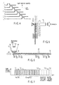
- FIGS. 1 to 10 A basic illumination principle of an illumination apparatus according to a first embodiment of the present invention will first be described with reference to FIGS. 1 to 10.
- An operation start command portion 1 as shown in FIG. 1 outputs a signal which commands start of an illumination operation by an illumination apparatus according to this embodiment.
- This signal which commands start of the operation is output in cooperation with a non-illustrated trigger switch which is operated by a user in order to start illumination. Alternatively, it may be output in cooperation with another non-illustrated function block which must activate the illumination operation.
- the signal output from the operation start command portion 1 is input to a luminous body movable control portion 2.
- a plurality of luminous bodies L 1 , L 2 , ..., L n are arranged and configured, and a luminous body movable portion 4 as movable means for mechanically enabling movement of these luminous bodies themselves is constituted.
- the luminous body movable control portion 2 gives a movement control quantity of each luminous body to this luminous body movable portion 4.
- the luminous body movable portion 4 spatially moves each luminous body at high speed in accordance with the given control quantity.
- the luminous body movable portion 4 one which can perform electrical driving and control such as an electromagnetic motor or an electrostatic motor is realistic, and selecting appropriate means in accordance with demanded conditions can suffice.
- a luminous body position detection portion 5 which constitutes a luminous body position detection sensor which is used to know a movement quantity or a movement timing of each luminous body is additionally provided in the vicinity of the luminous bodies.
- This luminous body position detection portion 5 detects a luminous body which should emit light by detecting a position of the luminous body moved to a specific light emission reference position 16 (refer to FIG. 2), and outputs a signal according to this detection.
- the signal output from the luminous body position detection portion 5 is input to a luminous body selection control portion 6.
- This luminous body selection control portion 6 and the luminous body movable control portion 2 constitute a light selection control portion as light selection controlling means.
- This luminous body selection control portion 6 selects a luminous body which should be caused to emit light based on the signal input thereto. Then, it outputs a control quantity which gives switching on/off of light emission or a light emission quantity to the selected luminous body.
- Luminous body drive portions 7 1 , 7 2 , ..., 7 n (in this case, the luminous bodies comprise n luminous bodies) as lighting means are constituted in association with the luminous bodies L 1 , L 2 , ..., L n .
- a control quantity output from the luminous body selection control portion 6 is input to any selected one of these luminous body drive portions 7 1 , 7 2 , ..., 7 n .
- the luminous bodies may comprise those which can emit light having different colors.
- the luminous bodies L 1 , L 2 , ..., L n may comprise those which can emit light having different colors.
- illumination light having mixed luminous colors of these luminous bodies can be created by using an afterglow phenomenon of the visual perception.
- This perceptible mixed color can be flexibly set based on combinations of luminous colors of the individual luminous bodies or individual light emission quantities.
- an illumination color characteristic setting portion 8 as illumination color characteristic setting means, a desired mixed color of the illumination light is set, and its information is supplied to the luminous body selection control portion 6.
- the luminous body selection control portion 6 outputs a control quantity according to the input information.
- a resort of setting an illumination color in the illumination color characteristic setting portion 8 may be one of mechanical means, an electrical means and software means.
- a content of the setting may be a direct content, e.g., a desired illumination color, or an indirect content, e.g., setting a light emission quantity with respect to each of the luminous bodies having different luminous colors. It is to be noted that, as the method of setting a mixed color, a method of controlling and changing a light emission time of each of the luminous bodies as well as the above-described method of setting a luminous color or a light emission quantity can be used.
- the plurality of luminous bodies are constituted, these luminous bodies move at a high speed, a luminous body placed at a specific position is caused to emit light like a single pulse, and the sequentially different luminous bodies are caused to continuously emit light, thereby obtaining continuous light emission which is equivalent to seemingly one luminous body.
- LED chips L 1 to L 7 are mounted on a support member 11 as light control member at equal intervals.
- This support member 11 has a mechanism which can slide in a direction indicated by an arrow A1 in the drawing at high speed by a voice coil motor 12 corresponding to the luminous body movable portion 4.
- reflection portions 13 are separately formed on a rear surface of the support member 11 so that they form pairs with the LED chips L 1 to L 7 .
- These reflection portions 13 as well as a light emitting element 14 and a light receiving element 15 constitute the luminous body position detection portion 5.
- These reflection portions 13 are fixedly arranged in such a manner that they can reflect light emitted from the light emitting element 14 in a predetermined direction and the reflected light can be received by the light receiving element 15. Therefore, when the reflection portion 13 reaches a predetermined light emission reference position 16 as shown in the drawing, the reflected light is input to the light receiving element 15. Therefore, whether an LED chip forming a pair exists at the light emission reference position 16 can be detected by counting the number of times of reflection from an initial reflection portion. It is to be noted that the light emission reference position 16 is a position at which the LED chip L 1 is placed in the illustrated state.
- this optical member As optical means which leads and applies light exiting from this LED chip to an illumination target area is arranged.
- this optical member comprises an optical lens 17 which condenses light emitted by the LED chip, and an optical lens 18 which controls a light path in such a manner that a desired irradiation target area is irradiated with the light condensed by the optical lens 17. That is, when the support member 11 moves and the LED chip passes the light emission reference position 16, the passing LED chip alone emits light, and this light is applied to the irradiation target area.
- FIG. 3 shows a relationship between an application current and a light emission quantity of the LED chip in the form of a modeled graph. That is, although the LED chip has a predetermined tolerance limit, but it can increase a quantity of emitted light when an application current is increased.
- the tolerance limit is of course affected and determined by characteristics of a material used, a composition defect, a heat radiation performance, electric conduction characteristics of peripheral electrodes and others. Additionally, by increasing the heat radiation performance in particular without changing these factors, a current which is not smaller than a maximum rating in continuous light can be given, thereby obtaining a large light quantity.
- FIG. 4 is a timing chart showing light emission timings of the LED chips L 1 to L 7 described in conjunction with FIG. 2.
- a horizontal axis represents a time axis, and a vertical axis represents a light emission quantity.
- each of the LED chips L 1 to L 7 is time-shared, and the light emission control is carried out with these time-shared LED chips being continuous.
- the LED chips L 1 to L 7 move with respect to the optical lenses 17 and 18 in the above description, but the optical lenses 17 and 18 may relatively move with respect to the LED chips L 1 to L 7 . It is needless to say that the same advantages can be obtained even if this structure is adopted.
- FIG. 5 shows a configuration in which the optical lenses 17 and 18 as the optical members are substituted by one rod lens 19 in the structure depicted in FIG. 2. Even if the rod lens 19 is used in this manner, the optical configuration which is used to obtain the illumination light can be likewise taken.
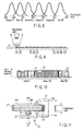
- FIGS. 6 and 7 show an example of a method of toning tints of the illumination light by using the illumination principle described in conjunction with FIGS. 2 to 4.
- LED chips L 1 to L 15 are arranged on the support member 11 at equal intervals.
- a position at which the LED chip L 1 is placed is determined as the light emission reference position 16.
- a condensing optical lens 17 is fixedly arranged in front of this light emission reference position 16 so that the illumination light can be obtained.
- a reflection surface 20 is constituted on each side of the LED chips in such a manner that the light emitted from side surfaces of the individual LED chips can be effectively applied to the front surface.
- the support member 11 moves in a direction indicated by an arrow A1 in the drawing at a high speed.
- the LED chips L 1 to L 2 are formed of a light emitting material which emits a red (R) color; the LED chips L 3 to L 10 , an orange (O) color; the LED chips L 11 to L 13 , a green (G) color; and the LED chips L 14 to L 15 , a blue (B) color.
- R red
- O orange
- G green
- B blue
- FIG. 7 shows a state of light emission quantities of the LED chips L 1 to L n (L 15 in this example) in accordance with these LED chips.
- the light emission quantity means a quantity of light emitted by the LED chip rather than a voltage and a current applied to the LED chip.
- the LED chips can sequentially emit light in the order of the LED chips L 1 to L 2 , ..., L 15 with respect to a time axis t.
- the LED chips L 11 to L 15 are controlled so that they do not emit light.
- a time that the LED chips L 11 to L 15 pass the light emission reference position 16 is such a very short period as that a human cannot perceive the light emitted by each of the LED chips, and a time which is, e.g., not more than 1/60 second is set.
- the illumination light becomes seemingly equivalent to the light obtained by mixing luminous colors of the LED chips L 1 to L 15 by the afterglow phenomenon of a human.
- the illumination light is perceived as light having a luminous color which aboundingly contains an orange color component and has a red color component mixed to some extent.
- Various color components are generally roughly classified into a red color, an orange color, a yellow color, a green color, a blue color and a purple color as visible light, and they can be grasped as light having spectral components in a wavelength band shown in FIG. 8, for example.
- the LED chips which emit light of the red (R) color, the green (G) color and the blue (B) color are generally often utilized, but elements which emit the orange (O) color, the yellow color and the purple (P) have also been developed. Therefore, by suitably mixing and using these chips as described above, various tints can be flexibly created.
- Utilizing such an advantage readily enables toning so that colors of the illumination light which can make the green color noticeable can be obtained when performing illumination to excellently show, e.g., green leaves of a tree. Moreover, illumination light which approximates to the spectrum of the sun light can be realized.
- FIGS. 9 and 10 are views illustrating a state in which individual irregularities in light emission quantity of the arranged LED chips can be absorbed by using the illumination principle of this embodiment when such irregularities exist in the structure equal to that described in conjunction with FIGS. 6 and 7.
- LED chips L 1 to L 5 emitting light of the red (R) color, LED chips L 6 to L 12 emitting light of the green (G) color and LED chips L 13 to L 15 emitting light of the blue (B) color are arranged.
- FIG. 10 shows a state of light emission quantities according to these chips. Even if light emission quantities obtained from the respective LED chips are not equal, for example, the red color is perceived as an average light emission quantity Ir obtained by subjecting the LED chips L 1 to L 5 to time average due to persistence of vision of a human. Likewise, the green color is perceived as an average light emission quantity Ig obtained by subjecting the LED chips L 6 to L 12 to time average, and the blue color is perceived as an average light emission quantity Ib obtained by subjecting the LED chips L 13 to L 15 to time average. This means that the averaged light emission quantity is perceived according to the illumination principle of this embodiment even if some irregularities are generated in the light emission quantities as well as waveform components of the LED chips in manufacture.
- the illumination light which is close to substantially homogeneous illumination light can be obtained without perceiving small irregularities in light emission quantities of the LED chips by a human according to the illumination principle of this embodiment even if such irregularities are generated.
- the average light emission quantity Ir, Ig or Ib when a desired light emission quantity should be intentionally controlled, one method of controlling this quantity is previously measuring a statistic of a light emission quantity of the LED chip to be adopted and calculating and utilizing an average value based on its normal distribution. Another method is detecting an actual average light emission quantity Ir, Ig or Ib by using any light detecting means and controlling an application voltage and current to a corresponding LED chip to have a desired average light emission quantity value.
- FIGS. 11 to 14 A second embodiment of an illumination apparatus using the illumination principle explained in conjunction with the first embodiment will now be described with reference to FIGS. 11 to 14.
- FIG. 11 is a view showing a structure of a flashlight 21 as the illumination apparatus according to the second embodiment of the present invention in the form of a cross-sectional structure.
- a drum support member 23 having a drum shape coupled with a rotating shaft 22 is used as a light control member in place of the linear support member 11 in FIG. 2.
- LED chips are closely arranged along an inner side surface of this drum support member 23 (in the drawing, these LED chips are illustrated as LED chip rows 24R and 24G and 24B which are continuously arranged in accordance with the same color and sectioned in accordance with each color (indicated by hatchings of different broken lines) set by a circumference in place of illustrating each of the LED chips for the sake of convenience).
- the rotating shaft 22 is supported by a rotating shaft bearing 25, and coupled with a drive motor 26 which is a movable portion as movable means.
- the drum support member 23 is partially inserted into a concave reflecting mirror 27 as an optical member in such a manner that the plurality of LED chips are positioned in the concave reflecting mirror 27.
- the LED chips emit light in the concave reflecting mirror 27, the emitted light is reflected on the concave reflecting mirror 27 and projected from an opening 28 of the concave reflecting mirror 27.
- a side of each LED chip has a reflection structure so that the light exiting from the side surface can be applied to the front side of the LED chip.
- the LED chip emits light only when it reaches a predetermined position (light emission reference position 29) of the concave reflecting mirror 27 in cooperation with the rotating drum support member 23, and this operation is continuously performed with respect to the LED chips which continuously move, thereby obtaining the intensive illumination light.
- the tints of the illumination light may be flexibly set based on luminous colors and the number of arrays of the LED chips as described with reference to FIGS. 6 and 7.
- the LED chips to be arranged is formed of a material which emits light having a near ultraviolet wavelength and a fluorescent substance which emits light in response to the near ultraviolet light is applied on the reflecting surface of the concave reflecting mirror 27, the same advantages can be obtained.
- tints of the illumination light can be set by appropriately mixing fluorescent substances which emit light having different colors.
- FIG. 12 shows an example in which the flashlight 21 is incorporated and used in place of a strobe of a camera (image capturing apparatus). That is, the flashlight 21 having the above-described structure as a strobe, an image sensor 31 as imaging means, and an imaging optical system 32 as imaging optical means are arranged and constituted in a camera main body 30 as shown in the drawing. Furthermore, a shutter button 33 is arranged at an upper portion of the camera main body 30.
- FIG. 13 is a function block diagram of such a camera. That is, a shutter portion 34 detects whether an operator has instructed an imaging operation based on whether the shutter button 33 is turned on, and inputs its detection signal to a timing control portion 35. This timing control portion 35 gives a command which executes preliminary illumination to an illumination portion 36 corresponding to the flashlight 21. Referring to a correspondence relationship in the basic block diagram in FIG. 1, the detection signal is input to the operation start command portion 1.
- the timing control portion 35 supplies a timing signal indicative of end of a predetermined preliminary illumination period to an image sensor exposure control portion 37, and instructs an exposure operation to the image sensor 31 from the image sensor exposure control portion 37, thereby executing the exposure.
- the illumination portion 36 continuously executes imaging illumination in a predetermined period.
- the image sensor exposure control portion 37 supplies an exposure operation end instruction to an image sensor read control portion 38.
- the image sensor read control portion 38 reads imaging information accumulated in the image sensor 31, converts this information into data, and temporarily accumulates this data in a storage portion 39. With end of this accumulation operation, a series of the imaging operation is terminated.
- FIG. 14 shows an example in which a white color LED is added as a luminous color, and illustrates a time-series operation when performing imaging by using a camera configured as shown in FIG. 12.
- the flashlight 21 starts a light emission operation. After a predetermined time elapses, the exposure of the image sensor 31 is effected. After an exposure time elapses, a signal is read from the image sensor 31. As a result, a series of the imaging operation is terminated.
- the illumination light of the white color is emitted from the flashlight 21, and a kind of a red-eye preventing effect is carried out.
- the illumination light having tints required for imaging conditions is toned and emitted while exploiting features of this illumination principle.
- a digital camera using the image sensor 31 is taken as an example as the camera in the above description, but it is needless to say that the flashlight 21 can be likewise applied to a film camera using a photographic film.
- the illumination apparatus according to this embodiment is an example applied to an illumination unit of an image projection display apparatus (which will be referred to as a projector apparatus hereinafter).
- FIG. 15 is a view showing a general view and basic structure of the projector apparatus. That is, a projector main body 40 comprises an illumination unit 41, a spatial light modulation element 42 as an illumination target area, and a projection optical system 43 based on a predetermined arrangement relationship.
- the illumination unit 41 is an illumination apparatus according to this embodiment having a light source and an illumination optical system as a basic structure.
- the spatial light modulation element 42 is light modulating means which receives light emitted from the illumination unit 41 and individually modulates the brightness in accordance with each pixel constituting an image.
- the projection optical system 43 is projection optical means for projecting light which has passed through the spatial light modulation element 42. The light emitted from the projection optical system 43 is projected on a screen 42, and an image is displayed.
- the spatial light modulation element 42 it is possible to utilize one using a transmission type liquid crystal, one using a reflection type liquid crystal, one using a fine mirror array which can perform a reflection angle control and others. In the present invention, any of these elements can be used. However, when the reflection type element is used, a structure of the optical system different from that depicted in FIG. 15 is required, but it is general, thereby eliminating the explanation.
- FIGS. 16A and 16B are views showing a detail of the illumination unit 41 as the illumination apparatus according to this embodiment. It is to be noted that FIG. 16A is a view showing the illumination unit 41 from above, and FIG. 16B is a view showing the same illumination unit 41 from a side surface.
- an LED chip row 45R whose luminous color is the red (R) color
- an LED chip row 45G whose luminous color is the green (G) color
- an LED chip row 45B whose luminous color is the blue (B) color
- This drums support member 46 is coupled with a rotating shaft 47.
- the rotating shaft 47 is held by a rotating shaft bearing 48, and can be rotated and driven in a direction indicated by an arrow A3 in the drawing by a drive motor 49 which is a movable portion as movable means.
- Ring-shaped power supply contact points 50a and 50b are also coupled with the rotating shaft 47. These power supply contact points 50a and 50b can be also rotated together with the drum support member 46.
- Such a structure has a secondary effect that heat radiation of the luminous bodies can be effectively performed since the luminous bodies themselves rotate.
- a forcible air-cooled mechanism can be readily constituted by utilizing the rotating drive force.
- two light emission reference positions 51a and 51b for the LED chips are set.
- Concave reflecting mirrors 52a and 52b are constituted at these light emission reference positions 51a and 51b.
- the light emitted from the LED chip which has reached the light emission reference positions 51a and 51b, is directly taken in by corresponding condenser lenses 53a and 53b or indirectly taken in by these lenses after reflected on the concave reflecting mirrors 52a and 52b.
- the light is applied to the same spatial light modulation element 42 in an overlapping manner.
- the arranged LED chips rows 45R, 45G and 45B also rotate in cooperation with the drum support member 46, and the LED chips placed at the light emission reference positions 51a and 51b instantaneously emit light. Power required for this light emission is supplied from the power supply contact points 50a and 50b, and used as a power which allows light emission of the LED chips which must emit light.
- a method of performing the light emission control a detailed embodiment is not presented, but one method is using the technique described in the first embodiment with reference to FIGS. 1 and 2.
- the high-luminance light emission with the enhanced heat radiation properties of the LED chips can be realized by configuring the illumination unit 41 for the projector apparatus with such a structure like the foregoing embodiments.
- a color surface sequential illumination mode which sequentially applies primary color illumination light of red, green and blue is required.
- the electric energy can be efficiently utilized.
- a conventional white lamp is used as a light source, since one color alone is used at the same time among primary colors which are constantly emitted in the color surface sequential illumination mode, any other colors are not utilized, and the energy must be lost.
- FIGS. 17 and 18 illustrate a structure from the light emission reference positions 51a and 51b for the LED chips to the spatial light modulation element 42 in FIGS. 16A and 16B and its illumination method by presenting a further detailed embodiment.
- FIG. 17 is a view schematically showing an illumination method which forms an image of an LED chip 54 on the spatial light modulation element 42 as an illumination target.
- a first irradiation area 55 and a second irradiation area 56 which have a conjugate relationship are defined.
- the optical system has such a structure as that the first irradiation area 55 is positioned in the vicinity of the LED chip 54 and the second irradiation area 56 is positioned in the vicinity of a position at which the spatial light modulation element 42 is arranged.
- the output light from the LED chip 54 is condensed by using a condenser microlens 57 (corresponding to the condenser lenses 53a and 53b). Further, the light from the plurality of LED chips 54 condensed by the condenser microlens 57 is caused to overlap on the spatial light modulation element 42 by an overlapping lens 58. By doing so, individual differences in brightness between the LED chips 54 can be averaged, thereby realizing homogenous illumination.
- the plurality of LED chips 54 may be used, and one LED chip 54 may be used if the brightness is sufficient.
- a substantially conjugate relationship is provided to the LED chips 54 and the spatial light modulation element 42 as an illumination target.
- the illumination optical system can have an isotropic lens structure which just provides magnifications. Furthermore, since the illumination light is not supplied to any area other than the display area of the spatial light modulation element 42, the illumination efficiency is improved.
- the spatial light modulation element 42 is a wide screen whose aspect ratio is 16:9, the LED chip 54 which has an aspect ratio of 16:9 according to this element is preferable.
- the illumination efficiency can be improved by adopting an anamorphic optical system having a vertical power larger than a horizontal power as the condenser microlens 57 or the overlapping lens 58.
- Another advantage of providing the conjugate relationship to the LED chip 54 and the spatial light modulation element 42 is that illumination irregularities are hard to be generated even if light distribution characteristics of the LED chip 54 have an angular dependence.
- the LED chip 54 actually has an electrode structure for electrical conduction, and existence of a bonding wire in the chip may generate the brightness distribution in the chip surface in some cases. In such a case, a shadow of the bonding can prevent the illumination irregularities from being generated by appropriately defocusing a position of the spatial light modulation element 42 from a position of an LED chip image. That is, in the LED chip 54 and the spatial light modulation element 42 arranged in the first irradiation area 55 and the second irradiation area 56 having the conjugate relationship, the LED chip 54 is arranged at a position deviating from the first irradiation area 55. By so doing, a blurry image of the LED chip 54 is projected on the spatial light modulation element 42 arranged in the second irradiation area 56, thereby averaging the brightness distribution in the surface.
- FIG. 18 shows an example of another illumination method in which the plurality of LED chips 54 are used as light sources.
- optical members which condense light projected from the LED chips 54 there is adopted a two-stage structure comprising condenser microlenses 57 as condensing optical elements and deflecting microlenses 59 as deflecting optical elements in accordance with the respective LED chips 54.
- the conjugate relationship is not provided to the LED chips 54 and the spatial light modulation element 42 as an illumination target, but the condenser microlenses 57 on the front stage of the optical members having the two-stage structure and the spatial light modulation element 42 have a conjugate positional relationship.
- the condenser microlenses 57 are arranged to be positioned in the vicinity of front focal positions of the deflecting microlenses 59 so that images of the LED chips 54 obtained by the condenser microlenses 57 are positioned in the vicinity of the deflecting microlenses 59.
- incident pupils formed on the condenser microlenses 57 can be relayed by the deflecting microlenses 59 and an overlapping lens 58 which is an overlapping optical element as overlapping means on the rear stage, thereby forming pupils at a position where the spatial light modulation element is arranged.
- An advantage of such an illumination method and structure is that individual differences in the brightness of the LED chips 54 can be averaged to obtain homogenous illumination since output light from the plurality of LEDs is superimposed. Moreover, there is another advantage that existence of the illumination target on the pupil surface can suppress illumination irregularities even if there is a brightness distribution in the surface of each LED chip.
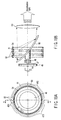
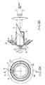
- FIGS. 19A and 19B are views showing a modification of the illumination unit 41 as the illumination apparatus according to the third embodiment.
- FIG. 19A is a view showing the illumination unit 41 from a rear surface
- FIG. 19B is a cross-sectional view taken along the line aa' in FIG. 19A.
- a concave reflecting mirror 60 which is a mirror member as a light control member is coupled with a rotating shaft 47.
- the rotating shaft 47 is supported by a rotating shaft bearing 48, and coupled with a drive motor 49.
- This drive motor 49 enables the concave reflecting mirror 60 to rotate in a direction indicated by an arrow A4 in the drawing at a high speed.
- a drum support member 61 with a drum shape is fixed and formed the rotating shaft 47 being used as a common central axis as shown in the drawing.
- LED chips 54 are closely arranged on two stages along an inner side surface of the drum support member 61. It is to be noted that the number of stages on which the LED chips 54 are arranged is not restricted to two, and the appropriate number of stages is set according to needs. In FIG.
- LED chips are drawn as LED chip rows 45R, 45G and 45B in such a manner that the chips having the same color are continuously arranged, they are sectioned in accordance with each color set by the circumference (indicated by hatchings of different broken lines), and the colors of emitted light are switched in the order of the red (R) color, the green (G) color and the blue (B) color in a process of one revolution. That is, illumination light capable of generating a field image with three primary colors required for a color image of one,frame can be obtained with respect to one revolution of the concave reflecting mirror 60.
- the LED chips 54 arranged on the drum support member 61 repeat sequential light emission in the time-sharing manner, and performs chain light emission to go around on the inner side surface (light emission points 62 go around).
- the concave reflecting mirror 60 performs a rotating operation
- the light emission control is performed in such a manner that the LED chips 54 having a correspondence relationship emit light in synchronization with this rotating operation. That is, there is achieved a structural relationship that the light emitted from the LED chips 54 is reflected and condensed by the concave reflecting mirror 60 and projected to the irradiation area through the optical lens 63 as an optical member.
- the LED chips themselves do not have to be rotated and moved as described in conjunction with the first and second embodiments. Therefore, transmission of an electrical control signal or supply of a power to the LED chips can be fixed and carried out, thereby greatly facilitating the design.
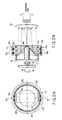
- FIGS. 20A and 20B are views showing another modification of the illumination unit 41 as the illumination apparatus according to the third embodiment. It is to be noted that FIG. 20A is a view showing the illumination unit 41 from a rear surface, and FIG. 20B is a cross-sectional view taken along the line bb' in FIG. 20B.
- a planar reflecting mirror 64 which is a mirror member as a light control member is coupled with a rotating shaft 47.
- the rotating shaft 47 is supported by a rotating shaft bearing 48, and coupled with a drive motor 49.
- This drive motor 49 forms a mechanism that the planar reflecting mirror 64 can rotate in a direction indicated by an arrow A5 in the drawing at a high speed.
- a drum support member 61 with a drum shape is fixed and formed with the rotating shaft 47 being used as a common central axis, and LED chips 54 are closely arranged on two stages along an inner side surface of the drum support member 61.
- two sets of condenser lenses 53 are supported by a rotating support member 65 integrated with the rotating shaft 47 in such a manner that these lenses can be rotated and moved in cooperation with the planar reflecting mirror 64.
- the number of stages on which the LED chips 54 are arranged is equal to the number of sets of condenser lenses 53.
- these numbers are not restricted thereto, and setting appropriate numbers according to needs can suffice.
- how to arrange of the LED chips 54 and how to emit light are the same as those in the modification shown in FIGS. 19A and 19B.
- the light emission control is effected in such a manner that the LED chips 54 having a correspondence relationship emit light in synchronization with a rotating operation of the planar reflecting mirror 64 when the planar reflecting mirror 64 performs this operation
- the condenser lenses 53 are provided in an arrangement relationship with which the light emitted from the LED chips 54 can be excellently taken in. That is, there is formed a structural relationship that the light from the activated LED chips 54 is once condensed by the condenser lenses 53, reflected by the planar reflecting mirror 64 so that its light path is bent, and projected to the irradiation target area through the optical lens 63.
- FIGS. 21A and 21B show an example obtained by further modifying the modification depicted in FIGS. 20A and 20B.
- FIG. 21A is a view showing the illumination unit 41 from a rear surface
- FIG. 21B is a cross-sectional view taken along the line cc'.
- like reference numerals denote elements which have the same functions as those in FIGS. 20A and 20B, thereby eliminating their explanation.
- two planar reflecting mirrors 64a and 64b and two condenser lenses 53a and 53b are configured as pairs with respect to a rotating shaft 47.
- the respective members are set so that they have a symmetrical positional relationship with respect to the rotating shaft 47.
- the light condensed by the condenser lens 53a is reflected by the planar reflecting mirror 64a, and the light condensed by the condenser lens 53b is reflected by the planar reflecting mirror 64b so that the light is applied to the irradiation target area through an optical lens 63.
- a structure that the LED chips 54a (54b) are closely arranged on two stages along an inner side surface of a drum support member 61 is the same as that depicted in FIGS. 19A and 19B and that illustrated in FIGS. 20A and 20B.
- two cycles of switching of colors of the light emitted in the order of the red (R) color, the green (G) color and the blue (B) color are prepared in a process of one revolution of the rotating support member 65 in a direction indicated by an arrow A6 in the drawing. That is, it is possible to obtain illumination light which can generate a field image of three primary colors required for color images of two frames with respect to one revolution of the drum support member 61.
- the two frames correspond to arrangement ranges of the LED chips described as an even-numbered frame and an odd-numbered frame in FIG. 21A.
- the number of revolutions of the drive motor 49 can be reduced to 1/2 of that in the example shown in FIGS. 19A and 19B or the example depicted in FIGS. 20A and 20B. Therefore, loads on the drive motor 49 can be reduced. Additionally, the number of LED chips which can emit light at the same time can be increased, thereby increasing a light quantity of the illumination light. However, each light emission time is increased as compared with the example shown in FIGS. 19A and 19B or FIGS. 20A and 20B. In a tolerance of the heat radiation performance or characteristics of the LED chips, the above-described effects can be realized without reducing the light emission quantity.
- FIG. 22A is a view showing the illumination unit 41 from a rear surface
- FIG. 22B is a cross-sectional view taken along the line dd' in FIG. 22A. It is to be noted that FIG. 22A shows LED chips rows by solid lines for clarifying the drawing, LED chips rows of which should be indicated by broken line because they cannot be seen from the rear surface.
- a prism 67 as a refraction member is integrated with a cylindrical rotating support member 66 coupled with a rotating shaft 47.
- the rotating shaft 47 is supported by a rotating shaft bearing 48, and coupled with a drive motor 49.
- This drive motor 49 forms a mechanism that the prism 67 can rotate in a direction indicated by an arrow A7 in the drawing at a high speed.
- a conical support member 68 with a conical shape is fixed and formed as shown in the drawing with the rotating shaft 47 being used as a common central axis.
- LED chips 54 are closely arranged on two stages along an inner side surface of this conical support member 68.
- a left stage in FIG. 22B is referred to as a stage a
- a right stage in the same is referred to as a stage b.
- the number of stages on which the LED chips 54 are arranged is not restricted to two, and the appropriate number of rows can be set according to needs.
- each LED chip these chips are illustrated as LED chip rows 45R, 45G and 45B in such a manner that the chips of the same color are continuously arranged, the LED chips are sectioned in accordance with each set color (indicated by hatchings of different broken lines) and colors of emitted light are switched in the order of the red (R) color, the green (G) color and the blue (B) color in a process of one revolution. That is, it is possible to obtain the illumination light which can generate a field image of three primary colors required for a color image of one frame with respect to one revolution of the conical support member 68.
- Condenser lenses 53 are configured to be equal to the modification shown in FIGS. 20A and 20B. That is, the light emitted from the LED chips 54 which have reached light emission points 62 is condensed by the condenser lenses 53, and caused to enter an incident surface 69 of the prism 67. The light exiting from an outgoing radiation surface 70 of this prism 67 is applied to the irradiation target area through an optical lens 63.
- the LED chips 54 arranged on the conical support member 68 repeat sequential light emission in the time-sharing manner, and perform chain light emission to go around the inner side surface (light emission points 62 go around). In this example, however, it is determined that the LED chip on one stage alone emits the light, namely, the LED chip 54 on the stage b does not emit the light when that on the stage a emits the light, and the LED chip 54 on the stage a does not emit the light when that on the stage b emits the light, as shown in FIG. 23. By so doing, assuming that all the chips on the stage b form the green (G) color and the stage a is formed while separating an area of the red (R) color and an area of the blue (B) color from each other as shown in FIG.
- G green
- R red
- B blue
- the following operation can be repeated as one cycle. That is, with the revolution of the conical support member 68, the LED chip 54 in the chip row 45R corresponding to the red (R) color on the stage a first emits the light for a predetermined period; this LED chip is switched to the LED chip 54 in the chip row 45G corresponding to the green (G) color on the stage b simultaneously with end of this light emission period of the red color, and the switched LED chip emits the light for a predetermined period; this LED chip is likewise switched to the LED chip 54 in the chip row 45B corresponding to the blue (B) color on the stage a simultaneously with end of the light emission period of the green color, and the switched LED chip emits the light for a predetermined period; and, at last, this LED chip is again switched to the LED chip 54 in the chip row 45G corresponding to the green (G) color on the stage b simultaneously with end of the light emission period of the green color, and the switched LED chip emits the light for a predetermined period. In this manner, it is, it
- FIGS. 19A and 19B FIGS. 20A and 20B and FIGS. 21A and 21B
- providing a non-light emission range between the adjacent LED chips having different luminous colors can avoid mixing of different colors in a switching state of the luminous colors.
- a light utilization efficiency in a period of providing such a range is reduced.
- image switching of the spatial light modulation element 42 of the projector apparatus can be also instantaneously performed, and a wasteful time, i.e., a non-light emission period can be eliminated, thereby improving the illumination efficiency.
- the illumination apparatus according to this embodiment is an example applied to an illumination unit of the projector apparatus, and has both a projector function and a general illumination function.
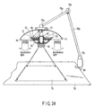
- FIG. 24 is a view showing a structure of a projector apparatus to which an illumination unit as the illumination apparatus according to this embodiment is applied.
- This drawing shows a part corresponding to a projector function and a part corresponding to an illumination reflecting umbrella in the form of a cross-sectional view, and shows any other apparatus part in the form of a perspective view.
- a cylindrical rotating shaft 71 is provided, and a fixed planar mirror 72 is set on an extended line of a central axis of the rotating shaft 71.
- the rotating shaft 71 is supported by a rotating shaft bearing 73, and can be rotated and driven by a non-illustrated drive motor.
- a rotating conical support member 74 with a conical shape is integrated with the rotating shaft 71 as shown in the drawing with the rotating shaft 71 being used as a common central axis.
- LED chips 54 are closely arranged on three stages along an inner side surface of this rotating conical support member 74.
- the number of stages on which the LED chips 54 are arranged is not restricted to three, and the appropriate number of stages can be set according to needs.
- each of the LED chips are illustrated as LED chip rows that the chips of the same color are continuously arranged, the LED chips are sectioned in accordance with each color set by the circumference (indicated by hatchings of different broken lines) and colors of light emitted in the order of the red (R) color, the green (G) color and the blue (B) color are switched in a process of one revolution. That is, it is possible to obtain the illumination light which can generate a field image of three primary colors required for a color image of one frame with respect to one revolution of the rotating conical support member 74.
- the light emitted from the LED chip 54 which has reached a light emission reference position 51 is taken in by each corresponding condenser lens 53, optically controlled into a state close to parallel light by an optical lens 63, then reflected by the fixed planar mirror 72 and applied to a spatial light modulation element 42 in an overlapping state.
- a single-plate transmission type liquid crystal is used as the spatial light modulation element 42.
- the light modulated in accordance with an image by this spatial light modulation element 42 is projected on a projection surface 75 by a projection optical system 43, resulting in a formed image.
- this projection surface 75 a part of a table surface 76 on which this projector apparatus is set is utilized.
- the condenser lens 53, the optical lens 63, the fixed planar mirror 72, the spatial light modulation element 42 and the projection optical system 43 are all configured to be fixed to the projector apparatus so that they all have a predetermined positional relationship, and they do not rotate.
- the LED chips 54 arranged to the rotating conical support member 74 repeat sequential light emission in the time-sharing manner and perform chain light emission with their rotation and movement based on the illumination principle described in conjunction with the first embodiment.
- this projector apparatus when utilized as a general illumination apparatus, rotation of the rotating conical support member 74 is caused to stand still, and all or a part of the LED chips 54 arranged to the rotating conical support member 74 are caused to emit light at the same time.
- the simultaneously emitted light is reflected by the umbrella reflecting member 77 as reflecting means, and applied to the table surface 76, and the table surface 76 is illuminated like a regular lighting equipment.
- These drive controlling means and switching means of the projector function and the general illumination function are not illustrated in detail, but they are additionally provided in this apparatus.
- the reflecting member 77 is supported by a flexibly movable support member comprising joints 78a, 78b and 78c and arms 79a and 79b and a base 80. Further, the base 80 is fixed to the edge of the table surface 76.
- the LED chips 54 arranged to the rotating conical support member 74 are not restricted to the primary luminous colors, and appropriately arranging LED chips which emit white light leads to the excellent color balance of illumination light when utilizing these chips as a regular illumination function, which is convenient. Furthermore, when utilizing the LED chips as the projector function, their white light does not have to be used. In any case, it is good enough to adjust the tints of the illumination light in accordance with preferences or applications of a user as described in conjunction with the first embodiment.
- the projector apparatus which has both the projector function which can effectively utilize the LEDs which are expected as light sources for coming generation and include various advantages and the general illumination function.
- an environment in which quite readily digitized image information is viewed is given by provision of the apparatus having the image display function as a part of the illumination equipment rather than viewing the image information in an additionally provided display.
- the displaying means is the projector, uses with the intimacy are enabled in daily life. For example, a display screen size can be flexibly selected, or the display portion can be set on a table or a desk and does not require a dedicated space.
- the projector apparatus can be incorporated in a general illumination equipment because the illumination unit itself can be reduced in size.
- the present invention can be utilized for, e.g., a car headlight, a stand illumination lamp, a spot light, a flashlight and others which are desired to efficiently illuminate a specific position. Further, it can be also utilized for an illumination unit for a projector apparatus like a data projector.
Landscapes
- Physics & Mathematics (AREA)
- General Physics & Mathematics (AREA)
- Engineering & Computer Science (AREA)
- General Engineering & Computer Science (AREA)
- Spectroscopy & Molecular Physics (AREA)
- Multimedia (AREA)
- Signal Processing (AREA)
- Projection Apparatus (AREA)
- Non-Portable Lighting Devices Or Systems Thereof (AREA)
- Microscoopes, Condenser (AREA)
- Stroboscope Apparatuses (AREA)
- Circuit Arrangement For Electric Light Sources In General (AREA)
Abstract
Description
Claims (33)
- An illumination apparatus which illuminates an illumination target area with light from light sources, comprising:a plurality of luminous bodies which are the light sources;luminous body drive portions configured to drive to light each of the plurality of luminous bodies;an optical member configured to lead and apply light exiting from a luminous body lighted by the luminous body drive portion to the illumination target area;a light control member configured to perform at least one of change of a light path of the light exiting from the luminous body with which the illumination target area is illuminated and movement of the luminous bodies;a movable portion configured to operably drive the light control member; anda light selection control portion configured to control at least one of the movable portion and the luminous body drive portions in such a manner that the light with which the illumination target area is illuminated is selected from the light exiting from the plurality of luminous bodies.
- The illumination apparatus according to claim 1, wherein the plurality of luminous bodies include at least a luminous body having first color characteristics and a luminous body having second color characteristics different from the first color characteristics.
- The illumination apparatus according to claim 2, wherein the light selection control portion controls at least one of the movable portion and the luminous body drive portions in such a manner that color characteristics of illumination light obtained by integrating light with which the illumination target area is illuminated for a predetermined time become desired characteristics.
- The illumination apparatus according to claim 3, wherein the desired color light is white color light.
- The illumination apparatus according to claim 3, wherein the desired color characteristics of color light have spectral characteristics approximating a sun light spectrum.
- The illumination apparatus according to claim 3, further comprising an illumination color characteristic setting portion configured to set the desired color characteristics, and
wherein the light selection control portion controls at least one of the movable portion and the luminous body drive portions in such a manner that the illumination target area is illuminated with illumination light having the color characteristics set by the illumination color characteristic setting portion. - The illumination apparatus according to claim 1, wherein each of the plurality of luminous bodies emits light in any wavelength band of light in a plurality of wavelength bands obtained by dividing a wavelength band visible to human eyes into a plurality of types of spectral components.
- The illumination apparatus according to claim 1, wherein spectral components of the light exiting from the plurality of luminous bodies are set in such a manner that the light with which the illumination target area is illuminated has all spectral components in the wavelength band visible to human eyes.
- The illumination apparatus according to claim 1, wherein the movable portion changes the light path by relatively moving the plurality of luminous bodies and the optical member.
- The illumination apparatus according to claim 1, wherein the light selection control portion selects the light with which the illumination target area is illuminated from the light exiting from the plurality of luminous bodies by controlling a light quantity of the light exiting from the luminous bodies by using the luminous body drive portions.
- The illumination apparatus according to claim 1, wherein the plurality of luminous bodies are luminous bodies having the same color characteristics.
- The illumination apparatus according to claim 1, wherein the optical member comprises a concave mirror.
- The illumination apparatus according to claim 1, wherein the optical member is constituted in such a manner that it can apply light in a plurality of separated irradiation areas to an irradiation target area, and
the light selection control portion selects light exiting from luminous bodies corresponding to the plurality of irradiation areas. - The illumination apparatus according to claim 13, wherein the plurality of irradiation areas are two-dimensionally arranged.
- The illumination apparatus according to claim 14, wherein the light selection control portion controls in such a manner that exiting light having the same color characteristics is simultaneously selected from the light exiting from the plurality of luminous bodies.
- The illumination apparatus according to claim 13, wherein the optical member includes a prism which synthesizes light from the plurality of irradiation areas.
- The illumination apparatus according to claim 1, wherein the optical member
irradiates a first irradiation area with the light exiting from the luminous body and irradiates an illumination target area as a second irradiation area with light passed through the first irradiation area, and
has such an optical structure that the first irradiation area and the second irradiation area have an optically conjugate relationship. - The illumination apparatus according to claim 17, wherein light emission surfaces of the plurality of luminous bodies are arranged in the first irradiation area.
- The illumination apparatus according to claim 17, wherein the optical member comprises a condensing optical element which is arranged in the vicinity of the first irradiation area, a deflecting optical element which is arranged in accordance with the condensing optical element, and
an overlapping optical element configured to lead light exiting from the deflecting optical element to the second irradiation area, and
an optical pupil is formed in each of the first irradiation area and the second irradiation area. - The illumination apparatus according to claim 1, wherein the light control member comprises a refracting member.
- The illumination apparatus according to claim 20, wherein the refracting member is a prism having an incident surface which relatively moves with respect to the plurality of luminous bodies so that an angle with respect to the light exiting from the plurality of luminous bodies sequentially varies in a time-series manner.
- The illumination apparatus according to claim 20, wherein the incident surface of the refracting member comprises a plurality of flat surfaces.
- The illumination apparatus according to claim 1, wherein the light control member comprises a mirror member.
- The illumination apparatus according to claim 23, wherein the mirror member is a mirror having a reflecting surface which relatively moves with respect to the plurality of luminous bodies so that an angle with respect to the light exiting from the plurality of luminous bodies sequentially varies in a time-series manner.
- The illumination apparatus according to claim 23, wherein the reflecting surface of the mirror has a curved surface and also has a function as the optical member.
- The illumination apparatus according to claim 23, wherein the reflecting surface of the mirror member comprises a plurality of flat surfaces.
- An image capturing apparatus which captures an image of a subject, comprising:wherein the light selection control portion of the illumination apparatus controls at least one of the movable portion and the luminous body drive portions in such a manner that illumination light is emitted in synchronization with the exposure start timing.an illumination apparatus including:a plurality of luminous bodies which are the light sources;luminous body drive portions configured to drive to light each of the plurality of luminous bodies;an optical member configured to lead and apply light exiting from a luminous body lighted by the luminous body drive portion to the illumination target area;a light control member configured to perform at least one of change of a light path of the light exiting from the luminous body with which the illumination target area is illuminated and movement of the luminous bodies;a movable portion configured to operably drive the light control member; anda light selection control portion configured to control at least one of the movable portion and the luminous body drive portions in such a manner that the light with which the illumination target area is illuminated is selected from the light exiting from the plurality of luminous bodies;an imaging optical system configured to form an image of the subject;an image sensor configured to expose and image the formed image of the subject; anda shutter button which operates an exposure start timing of the image sensor,
- The image capturing apparatus according to claim 27, wherein the image sensor starts exposure when a predetermined time elapses after the shutter button is pressed, and the light selection control portion of the illumination apparatus emits the illumination light immediately after the shutter button is pressed.
- A projector apparatus which projects an image corresponding to image information on a projection surface, comprising:an illumination apparatus including:a plurality of luminous bodies which are the light sources;luminous body drive portions configured to drive to light each of the plurality of luminous bodies;an optical member configured to lead and apply light exiting from a luminous body lighted by the luminous body drive portion to the illumination target area;a light control member configured to perform at least one of change of a light path of the light exiting from the luminous body with which the illumination target area is illuminated and movement of the luminous bodies;a movable portion configured to operably drive the light control member; anda light selection control portion configured to control at least one of the movable portion and the luminous body drive portions in such a manner that the light with which the illumination target area is illuminated is selected from the light exiting from the plurality of luminous bodies;a spatial light modulation element configured to perform one of transmission and reflection by modulating illumination light emitted from the illumination apparatus in accordance with the image information; anda projection optical system configured to project the light modulated by the spatial light modulation element on the projection surface.
- The projector apparatus according to claim 29, further comprising a reflecting member which can illuminate the projection surface with light exiting from the luminous body in an optical path different from the optical member and the projection optical system.
- An illumination apparatus which illuminates an illumination target area with light from light sources, comprising:a plurality of luminous bodies which are the light sources;lighting means for driving to light each of the plurality of luminous bodies;optical means for leading and applying light exiting from a luminous body lighted by the lighting means to the illumination target area;a light control member for performing at least one of change of a light path of the light exiting from the luminous body with which the illumination target area is illuminated and movement of the luminous bodies;movable means for operably driving the light control member; andlight selection control means for controlling at least one of the movable means and the lighting means in such a manner that the light with which the illumination target area is illuminated is selected from the light exiting from the plurality of luminous bodies.
- An image capturing apparatus which captures an image of a subject, comprising:wherein the light selection control means of the illumination apparatus controls at least one of the movable means and the lighting means in such a manner that illumination light is emitted in synchronization with the exposure start timing.an illumination apparatus including:a plurality of luminous bodies which are the light sources;lighting means for driving to light each of the plurality of luminous bodies;optical means for leading and applying light exiting from a luminous body lighted by the lighting means to the illumination target area;a light control member for performing at least one of change of a light path of the light exiting from the luminous body with which the illumination target area is illuminated and movement of the luminous bodies;movable means for operably driving the light control member; andlight selection control means for controlling at least one of the movable means and the lighting means in such a manner that the light with which the illumination target area is illuminated is selected from the light exiting from the plurality of luminous bodies;imaging optical means for forming an image of the subject;image sensing means for exposing and imaging the formed image of the subject; anda shutter button for operating an exposure start timing of the image sensing means,
- A projector apparatus which projects an image corresponding to image information on a projection surface, comprising:an illumination apparatus including:a plurality of luminous bodies which are the light sources;lighting means for driving to light each of the plurality of luminous bodies;optical means for leading and applying light exiting from a luminous body lighted by the lighting means to the illumination target area;a light control member for performing at least one of change of a light path of the light exiting from the luminous body with which the illumination target area is illuminated and movement of the luminous bodies;movable means for operably driving the light control member; andlight selection control means for controlling at least one of the movable means and the lighting means in such a manner that the light with which the illumination target area is illuminated is selected from the light exiting from the plurality of luminous bodies;light modulation means for performing one of transmission and reflection by modulating illumination light emitted from the illumination apparatus in accordance with the image information; andprojection optical means for projecting the light modulated by the light modulation means on the projection surface.
Applications Claiming Priority (3)
| Application Number | Priority Date | Filing Date | Title |
|---|---|---|---|
| JP2002151038A JP3989302B2 (en) | 2002-05-24 | 2002-05-24 | Illumination device and projector device |
| JP2002151038 | 2002-05-24 | ||
| PCT/JP2003/006211 WO2003100315A1 (en) | 2002-05-24 | 2003-05-19 | Illuminating device, and photographing device and projector device using this illuminating device |
Publications (3)
| Publication Number | Publication Date |
|---|---|
| EP1508740A1 true EP1508740A1 (en) | 2005-02-23 |
| EP1508740A4 EP1508740A4 (en) | 2008-09-03 |
| EP1508740B1 EP1508740B1 (en) | 2010-01-27 |
Family
ID=29561242
Family Applications (1)
| Application Number | Title | Priority Date | Filing Date |
|---|---|---|---|
| EP03730518A Expired - Lifetime EP1508740B1 (en) | 2002-05-24 | 2003-05-19 | Illuminating device, and photographing device and projector device using this illuminating device |
Country Status (6)
| Country | Link |
|---|---|
| US (2) | US7128423B2 (en) |
| EP (1) | EP1508740B1 (en) |
| JP (1) | JP3989302B2 (en) |
| CN (1) | CN1656337B (en) |
| DE (1) | DE60331143D1 (en) |
| WO (1) | WO2003100315A1 (en) |
Cited By (10)
| Publication number | Priority date | Publication date | Assignee | Title |
|---|---|---|---|---|
| EP1395064A3 (en) * | 2002-08-07 | 2005-08-24 | Olympus Optical Co., Ltd. | Illumination apparatus and projector display apparatus |
| WO2006107358A1 (en) * | 2005-03-30 | 2006-10-12 | Tte Technology, Inc. | A system and method for projecting video onto a screen |
| WO2007050764A1 (en) * | 2005-10-26 | 2007-05-03 | Hewlett-Packard Development Company, L.P. | A projection light source having multiple light emitting diodes |
| EP2009496A1 (en) * | 2007-06-26 | 2008-12-31 | Samsung Electronics Co., Ltd. | Optical Scanning Unit |
| EP2003490A4 (en) * | 2006-03-31 | 2009-12-02 | Nikon Corp | Projector |
| EP2490070A1 (en) * | 2011-02-17 | 2012-08-22 | Nikon Corporation | Illuminating optical system and projector device |
| CN102809098A (en) * | 2012-07-11 | 2012-12-05 | 江苏好的节能光电科技有限公司 | Automatic focusing LED (Light Emitting Diode) searching lamp |
| WO2013132386A1 (en) * | 2012-03-08 | 2013-09-12 | Koninklijke Philips N.V. | Controllable high luminance illumination with moving light-sources |
| EP3537213A1 (en) * | 2018-03-09 | 2019-09-11 | Nichia Corporation | Light source device |
| EP2726777B1 (en) * | 2011-06-29 | 2020-03-11 | Harman Professional Denmark ApS | Color mixing illumination device |
Families Citing this family (60)
| Publication number | Priority date | Publication date | Assignee | Title |
|---|---|---|---|---|
| JP3989302B2 (en) * | 2002-05-24 | 2007-10-10 | オリンパス株式会社 | Illumination device and projector device |
| JP4046585B2 (en) * | 2002-10-01 | 2008-02-13 | オリンパス株式会社 | LIGHTING DEVICE AND PROJECTION DISPLAY DEVICE USING THE LIGHTING DEVICE |
| JP2005173487A (en) * | 2003-12-15 | 2005-06-30 | Olympus Corp | Fluorescence microscope and computer program |
| JP2005181579A (en) * | 2003-12-18 | 2005-07-07 | Olympus Corp | Lighting device and display device using the same |
| JP2005189472A (en) * | 2003-12-25 | 2005-07-14 | Olympus Corp | Display unit and lighting device thereof |
| JP2005189653A (en) * | 2003-12-26 | 2005-07-14 | Olympus Corp | Image projector |
| JP4546741B2 (en) * | 2004-01-08 | 2010-09-15 | オリンパス株式会社 | Fluorescence microscope |
| JP2005257790A (en) * | 2004-03-09 | 2005-09-22 | Olympus Corp | Illumination apparatus and image projection apparatus using the same |
| JP2006018196A (en) * | 2004-07-05 | 2006-01-19 | Sanyo Electric Co Ltd | Illuminator and projection video display device |
| JP2006023436A (en) * | 2004-07-07 | 2006-01-26 | Olympus Corp | Illuminating apparatus and projector |
| JP2006023627A (en) * | 2004-07-09 | 2006-01-26 | Olympus Corp | Lighting device and image projection apparatus |
| JP4603836B2 (en) * | 2004-08-31 | 2010-12-22 | キヤノン株式会社 | Imaging apparatus, control method therefor, program, and recording medium |
| JP4540458B2 (en) * | 2004-12-06 | 2010-09-08 | Hoya株式会社 | LIGHTING DEVICE USING SEMICONDUCTOR LIGHT EMITTING DEVICE AND CAMERA |
| JP2006195069A (en) * | 2005-01-12 | 2006-07-27 | Konica Minolta Photo Imaging Inc | Illuminating device and illumination control method |
| EP1689148B1 (en) * | 2005-02-03 | 2009-04-01 | Sony Ericsson Mobile Communications AB | An optical device |
| JP2006330176A (en) | 2005-05-24 | 2006-12-07 | Olympus Corp | Light source device |
| JP2006343500A (en) * | 2005-06-08 | 2006-12-21 | Olympus Corp | Light source device and projection optical device |
| JP2007003561A (en) * | 2005-06-21 | 2007-01-11 | Seiko Epson Corp | Projection apparatus and projector |
| JP2007047544A (en) * | 2005-08-11 | 2007-02-22 | Fujifilm Holdings Corp | Strobe apparatus |
| US7497579B2 (en) * | 2005-09-02 | 2009-03-03 | Hewlett-Packard Development Company, L.P. | Active color wheel |
| WO2007056541A2 (en) * | 2005-11-08 | 2007-05-18 | Young Garrett J | Apparatus and method for generating light from multi - primary colors |
| JP4540118B2 (en) * | 2006-03-16 | 2010-09-08 | スタンレー電気株式会社 | Vehicle lighting |
| US8519566B2 (en) | 2006-03-28 | 2013-08-27 | Wireless Environment, Llc | Remote switch sensing in lighting devices |
| US8203445B2 (en) * | 2006-03-28 | 2012-06-19 | Wireless Environment, Llc | Wireless lighting |
| US8669716B2 (en) | 2007-08-30 | 2014-03-11 | Wireless Environment, Llc | Wireless light bulb |
| JP4900943B2 (en) * | 2006-12-25 | 2012-03-21 | 独立行政法人産業技術総合研究所 | Modified double-stranded RNA with excellent nuclease resistance and RNA interference effect |
| JP2008305710A (en) | 2007-06-08 | 2008-12-18 | Olympus Corp | Light source device for illumination |
| US8085218B2 (en) * | 2007-06-28 | 2011-12-27 | International Business Machines Corporation | Providing a floating alphanumeric/graphical display without moving electronics |
| JP5074278B2 (en) * | 2008-04-21 | 2012-11-14 | オリンパス株式会社 | Illumination device and illumination imaging device |
| JP2009302104A (en) * | 2008-06-10 | 2009-12-24 | Eko Instruments Trading Co Ltd | Light projector |
| JP2009297436A (en) | 2008-06-17 | 2009-12-24 | Olympus Corp | Light source apparatus and endoscope system |
| WO2010063001A1 (en) | 2008-11-26 | 2010-06-03 | Wireless Environment, Llc | Wireless lighting devices and applications |
| CN101761862B (en) * | 2008-12-24 | 2011-12-07 | 富士迈半导体精密工业(上海)有限公司 | Illumination device |
| CN101893173B (en) * | 2009-05-20 | 2012-03-28 | 富士迈半导体精密工业(上海)有限公司 | Lighting system |
| US20120233034A1 (en) * | 2009-08-19 | 2012-09-13 | Compurants Limited | Combined table and computer-controlled projector unit |
| WO2011062164A1 (en) * | 2009-11-20 | 2011-05-26 | オリンパスメディカルシステムズ株式会社 | Medical light source device and medical system |
| JP5146566B2 (en) * | 2011-05-16 | 2013-02-20 | セイコーエプソン株式会社 | Projection apparatus and projector |
| JP5966363B2 (en) | 2011-06-20 | 2016-08-10 | 株式会社リコー | Light source device and image projection device |
| CN102997174A (en) * | 2011-09-14 | 2013-03-27 | 湖南明和光电设备有限公司 | LED (Light Emitting Diode) lamp with double color change and adjustable beam angle |
| JP6083172B2 (en) * | 2011-12-26 | 2017-02-22 | セイコーエプソン株式会社 | Lighting device |
| CN102722077A (en) * | 2012-05-24 | 2012-10-10 | 深圳市绎立锐光科技开发有限公司 | Light source system and projection system related to light source system |
| JP6183582B2 (en) * | 2013-02-14 | 2017-08-23 | セイコーエプソン株式会社 | Lighting device and projector |
| JP6236811B2 (en) | 2013-03-14 | 2017-11-29 | 株式会社リコー | Light source unit, illumination device, and image projection device |
| JP6349784B2 (en) * | 2013-03-14 | 2018-07-04 | 株式会社リコー | Light source unit, illumination device, and image projection device |
| CN104657973B (en) * | 2013-11-25 | 2018-12-14 | 联想(北京)有限公司 | A kind of image processing method, electronic equipment and control system |
| EP2882178B1 (en) | 2013-12-03 | 2015-12-02 | Axis AB | An illumination device for a camera |
| KR200479099Y1 (en) * | 2014-02-03 | 2015-12-17 | 광주대학교산학협력단 | Led light for camera |
| DE112016002924B4 (en) * | 2015-07-29 | 2020-08-13 | Fujifilm Corporation | Projection type display device and projection control method |
| US10636302B2 (en) * | 2015-12-22 | 2020-04-28 | Koito Manufacturing Co., Ltd. | Vehicle illumination device, vehicle and illumination control system |
| US10782599B1 (en) * | 2017-02-15 | 2020-09-22 | Designs For Vision, Inc. | LED light blending assembly |
| US10393348B2 (en) * | 2017-02-24 | 2019-08-27 | Glint Photonics, Inc. | Configurable luminaire |
| WO2020010933A1 (en) * | 2018-07-13 | 2020-01-16 | 华域视觉科技(上海)有限公司 | Rotating light source for vehicle lamp, and control method and application therefor |
| CN110195844A (en) * | 2019-06-26 | 2019-09-03 | 深圳恩生科技有限公司 | A kind of rotating LED car light |
| JP7363411B2 (en) * | 2019-11-25 | 2023-10-18 | セイコーエプソン株式会社 | Light source device and projector |
| CN110928126B (en) * | 2019-12-09 | 2020-09-22 | 四川长虹电器股份有限公司 | Projection equipment capable of automatically adjusting brightness |
| CN114063374B (en) * | 2020-08-06 | 2025-01-07 | 深圳光峰科技股份有限公司 | Light source device and projection equipment |
| EP4427096A4 (en) * | 2021-11-03 | 2025-09-03 | Lumileds Llc | ACTUATOR FOR BLURRING DARK BANDS IN LIGHTING |
| WO2023112593A1 (en) | 2021-12-14 | 2023-06-22 | 日亜化学工業株式会社 | Light source device |
| JPWO2024038804A1 (en) * | 2022-08-18 | 2024-02-22 | ||
| CN117806106A (en) * | 2022-09-26 | 2024-04-02 | 中强光电股份有限公司 | Light source components and projection devices |
Family Cites Families (27)
| Publication number | Priority date | Publication date | Assignee | Title |
|---|---|---|---|---|
| AT397639B (en) | 1992-03-09 | 1994-05-25 | Zizala Lichtsysteme Gmbh | VEHICLE LIGHTING SYSTEM |
| JPS6197831A (en) | 1984-10-18 | 1986-05-16 | Canon Inc | Exposure device |
| JPH0828543A (en) | 1994-07-21 | 1996-02-02 | Hidenori Ushiyama | Piston crank connecting rod |
| JP3334833B2 (en) | 1995-08-24 | 2002-10-15 | 松下電器産業株式会社 | Linear lighting device |
| JP3645350B2 (en) | 1996-04-09 | 2005-05-11 | シチズン時計株式会社 | Display device |
| JP4050802B2 (en) * | 1996-08-02 | 2008-02-20 | シチズン電子株式会社 | Color display device |
| JPH10293233A (en) | 1997-04-21 | 1998-11-04 | Nippon Steel Corp | Fiber optic light guide |
| JPH10333588A (en) * | 1997-05-30 | 1998-12-18 | Ichikoh Ind Ltd | Backlight for color liquid crystal display |
| JPH1132278A (en) | 1997-07-10 | 1999-02-02 | Fuji Xerox Co Ltd | Projecting device |
| US6227669B1 (en) | 1998-05-26 | 2001-05-08 | Industrial Technology Research Institute | Illumination device and image projection apparatus comprising the device |
| JP3795683B2 (en) * | 1998-11-05 | 2006-07-12 | 株式会社リコー | Optical device |
| WO2000033122A1 (en) | 1998-11-27 | 2000-06-08 | Matsushita Electric Industrial Co., Ltd. | Polarized light illuminator, image display, portable information terminal, head-up display, method for producing diffraction optical device, method for producing polarized light illuminator, and method for producing image display |
| JP4332648B2 (en) | 1999-04-07 | 2009-09-16 | レーザーテック株式会社 | Light source device |
| JP2000356757A (en) * | 1999-04-16 | 2000-12-26 | Matsushita Electric Ind Co Ltd | Polarized illumination device |
| JP2000331520A (en) | 1999-05-18 | 2000-11-30 | Canon Inc | Illumination device and display device using the illumination device |
| JP2001111826A (en) * | 1999-10-07 | 2001-04-20 | Canon Inc | Image processing apparatus and method |
| EP1234140B2 (en) * | 1999-11-18 | 2015-11-25 | Philips Lighting North America Corporation | Systems and methods for generating and modulating illumination conditions |
| JP4495814B2 (en) * | 1999-12-28 | 2010-07-07 | アビックス株式会社 | Dimmable LED lighting fixture |
| JP2001209342A (en) * | 2000-01-24 | 2001-08-03 | Matsushita Electric Ind Co Ltd | Video display device |
| DE10031303A1 (en) * | 2000-06-27 | 2002-01-10 | Arnold & Richter Kg | Lighting device with light emitting diodes (LED), lighting method and method for image recording with such an LED lighting device |
| JP4288553B2 (en) * | 2000-07-25 | 2009-07-01 | 富士フイルム株式会社 | Camera strobe device |
| JP4174195B2 (en) * | 2001-05-28 | 2008-10-29 | キヤノン株式会社 | Image display device |
| US6749310B2 (en) * | 2001-09-07 | 2004-06-15 | Contrast Lighting Services, Inc. | Wide area lighting effects system |
| FR2831382B1 (en) | 2001-10-19 | 2008-12-26 | Valeo Vision | ELECTROLUMINESCENT DIODE LIGHTING OR SIGNALING DEVICE |
| US6889435B1 (en) * | 2002-05-06 | 2005-05-10 | Dana Corporation | Attachment of metal components by thermal drilling |
| JP3989302B2 (en) * | 2002-05-24 | 2007-10-10 | オリンパス株式会社 | Illumination device and projector device |
| JP3989412B2 (en) * | 2002-10-21 | 2007-10-10 | オリンパス株式会社 | Illumination device and image projection device |
-
2002
- 2002-05-24 JP JP2002151038A patent/JP3989302B2/en not_active Expired - Fee Related
-
2003
- 2003-05-19 CN CN038118742A patent/CN1656337B/en not_active Expired - Fee Related
- 2003-05-19 WO PCT/JP2003/006211 patent/WO2003100315A1/en not_active Ceased
- 2003-05-19 DE DE60331143T patent/DE60331143D1/en not_active Expired - Lifetime
- 2003-05-19 EP EP03730518A patent/EP1508740B1/en not_active Expired - Lifetime
-
2004
- 2004-11-19 US US10/994,131 patent/US7128423B2/en not_active Expired - Fee Related
-
2006
- 2006-09-18 US US11/522,707 patent/US7322705B2/en not_active Expired - Fee Related
Cited By (21)
| Publication number | Priority date | Publication date | Assignee | Title |
|---|---|---|---|---|
| EP1395064A3 (en) * | 2002-08-07 | 2005-08-24 | Olympus Optical Co., Ltd. | Illumination apparatus and projector display apparatus |
| US6991336B2 (en) | 2002-08-07 | 2006-01-31 | Olympus Corporation | Illumination apparatus and projector display apparatus |
| US7080909B2 (en) | 2002-08-07 | 2006-07-25 | Olympus Corporation | Illumination apparatus and projector display apparatus |
| WO2006107358A1 (en) * | 2005-03-30 | 2006-10-12 | Tte Technology, Inc. | A system and method for projecting video onto a screen |
| US9049412B2 (en) | 2005-03-30 | 2015-06-02 | Tte Technology, Inc. | System and method for projecting video onto a screen |
| US7506985B2 (en) | 2005-10-26 | 2009-03-24 | Hewlett-Packard Development Company, L.P. | Projection light source having multiple light emitting diodes |
| WO2007050764A1 (en) * | 2005-10-26 | 2007-05-03 | Hewlett-Packard Development Company, L.P. | A projection light source having multiple light emitting diodes |
| EP2003490A4 (en) * | 2006-03-31 | 2009-12-02 | Nikon Corp | Projector |
| US11438558B2 (en) | 2006-03-31 | 2022-09-06 | Nikon Corporation | Projection device |
| US10855961B2 (en) | 2006-03-31 | 2020-12-01 | Nikon Corporation | Projection device |
| US9219895B2 (en) | 2006-03-31 | 2015-12-22 | Nikon Corporation | Projection device |
| EP2009496A1 (en) * | 2007-06-26 | 2008-12-31 | Samsung Electronics Co., Ltd. | Optical Scanning Unit |
| EP2490070A1 (en) * | 2011-02-17 | 2012-08-22 | Nikon Corporation | Illuminating optical system and projector device |
| US8746892B2 (en) | 2011-02-17 | 2014-06-10 | Nikon Corporation | Illuminating optical system and projector device |
| EP2726777B1 (en) * | 2011-06-29 | 2020-03-11 | Harman Professional Denmark ApS | Color mixing illumination device |
| WO2013132386A1 (en) * | 2012-03-08 | 2013-09-12 | Koninklijke Philips N.V. | Controllable high luminance illumination with moving light-sources |
| US9333904B2 (en) | 2012-03-08 | 2016-05-10 | Koninklijke Philips N.V. | Controllable high luminance illumination with moving light-sources |
| CN102809098B (en) * | 2012-07-11 | 2014-06-18 | 江苏好的节能光电科技有限公司 | Automatic focusing LED (Light Emitting Diode) searching lamp |
| CN102809098A (en) * | 2012-07-11 | 2012-12-05 | 江苏好的节能光电科技有限公司 | Automatic focusing LED (Light Emitting Diode) searching lamp |
| EP3537213A1 (en) * | 2018-03-09 | 2019-09-11 | Nichia Corporation | Light source device |
| EP3805859A1 (en) * | 2018-03-09 | 2021-04-14 | Nichia Corporation | Light source device |
Also Published As
| Publication number | Publication date |
|---|---|
| CN1656337B (en) | 2010-08-18 |
| CN1656337A (en) | 2005-08-17 |
| WO2003100315B1 (en) | 2004-05-13 |
| US7128423B2 (en) | 2006-10-31 |
| EP1508740B1 (en) | 2010-01-27 |
| JP2003346503A (en) | 2003-12-05 |
| WO2003100315A1 (en) | 2003-12-04 |
| EP1508740A4 (en) | 2008-09-03 |
| JP3989302B2 (en) | 2007-10-10 |
| US7322705B2 (en) | 2008-01-29 |
| US20070013879A1 (en) | 2007-01-18 |
| US20050062937A1 (en) | 2005-03-24 |
| DE60331143D1 (en) | 2010-03-18 |
Similar Documents
| Publication | Publication Date | Title |
|---|---|---|
| EP1508740B1 (en) | Illuminating device, and photographing device and projector device using this illuminating device | |
| US6991336B2 (en) | Illumination apparatus and projector display apparatus | |
| JP4046585B2 (en) | LIGHTING DEVICE AND PROJECTION DISPLAY DEVICE USING THE LIGHTING DEVICE | |
| EP1544671B1 (en) | Illumination apparatus with movable LEDs and image projection apparatus using the same | |
| US10031406B2 (en) | Image projection apparatus and method of controlling image projection apparatus | |
| US7252392B2 (en) | Illumination apparatus and image projection apparatus using the illumination apparatus | |
| JP2001209342A (en) | Video display device | |
| JP2012247491A (en) | Lighting device and projection display unit having the lighting device | |
| JP2004163527A (en) | Light amount control device, illumination device, control method thereof, and projector | |
| US20060139954A1 (en) | Display system and lighting device used therein | |
| JP2008546023A (en) | Multi-position illumination system and projection display system using the same | |
| US20100214535A1 (en) | Fundus camera | |
| JP2004004359A (en) | Image display device | |
| JP2006310320A (en) | Lighting system and projection display device | |
| EP1869897B1 (en) | A system and method for projecting video onto a screen | |
| JP2006286648A (en) | Illumination device and imaging device | |
| JP2004013107A (en) | Illumination optical element | |
| JP2007219263A (en) | Illumination method and image display apparatus using the method |
Legal Events
| Date | Code | Title | Description |
|---|---|---|---|
| PUAI | Public reference made under article 153(3) epc to a published international application that has entered the european phase |
Free format text: ORIGINAL CODE: 0009012 |
|
| 17P | Request for examination filed |
Effective date: 20041122 |
|
| AK | Designated contracting states |
Kind code of ref document: A1 Designated state(s): AT BE BG CH CY CZ DE DK EE ES FI FR GB GR HU IE IT LI LU MC NL PT RO SE SI SK TR |
|
| RBV | Designated contracting states (corrected) |
Designated state(s): DE FR GB |
|
| A4 | Supplementary search report drawn up and despatched |
Effective date: 20080805 |
|
| 17Q | First examination report despatched |
Effective date: 20090430 |
|
| GRAP | Despatch of communication of intention to grant a patent |
Free format text: ORIGINAL CODE: EPIDOSNIGR1 |
|
| GRAS | Grant fee paid |
Free format text: ORIGINAL CODE: EPIDOSNIGR3 |
|
| GRAA | (expected) grant |
Free format text: ORIGINAL CODE: 0009210 |
|
| AK | Designated contracting states |
Kind code of ref document: B1 Designated state(s): DE FR GB |
|
| REG | Reference to a national code |
Ref country code: GB Ref legal event code: FG4D |
|
| REF | Corresponds to: |
Ref document number: 60331143 Country of ref document: DE Date of ref document: 20100318 Kind code of ref document: P |
|
| PLBE | No opposition filed within time limit |
Free format text: ORIGINAL CODE: 0009261 |
|
| STAA | Information on the status of an ep patent application or granted ep patent |
Free format text: STATUS: NO OPPOSITION FILED WITHIN TIME LIMIT |
|
| 26N | No opposition filed |
Effective date: 20101028 |
|
| REG | Reference to a national code |
Ref country code: FR Ref legal event code: PLFP Year of fee payment: 13 |
|
| PGFP | Annual fee paid to national office [announced via postgrant information from national office to epo] |
Ref country code: DE Payment date: 20150512 Year of fee payment: 13 Ref country code: GB Payment date: 20150513 Year of fee payment: 13 |
|
| PGFP | Annual fee paid to national office [announced via postgrant information from national office to epo] |
Ref country code: FR Payment date: 20150508 Year of fee payment: 13 |
|
| REG | Reference to a national code |
Ref country code: DE Ref legal event code: R119 Ref document number: 60331143 Country of ref document: DE |
|
| GBPC | Gb: european patent ceased through non-payment of renewal fee |
Effective date: 20160519 |
|
| REG | Reference to a national code |
Ref country code: FR Ref legal event code: ST Effective date: 20170131 |
|
| PG25 | Lapsed in a contracting state [announced via postgrant information from national office to epo] |
Ref country code: DE Free format text: LAPSE BECAUSE OF NON-PAYMENT OF DUE FEES Effective date: 20161201 Ref country code: FR Free format text: LAPSE BECAUSE OF NON-PAYMENT OF DUE FEES Effective date: 20160531 |
|
| PG25 | Lapsed in a contracting state [announced via postgrant information from national office to epo] |
Ref country code: GB Free format text: LAPSE BECAUSE OF NON-PAYMENT OF DUE FEES Effective date: 20160519 |