EP1508488A1 - Installation of compressed air production for a vehicle and method of operating the same - Google Patents
Installation of compressed air production for a vehicle and method of operating the same Download PDFInfo
- Publication number
- EP1508488A1 EP1508488A1 EP04019344A EP04019344A EP1508488A1 EP 1508488 A1 EP1508488 A1 EP 1508488A1 EP 04019344 A EP04019344 A EP 04019344A EP 04019344 A EP04019344 A EP 04019344A EP 1508488 A1 EP1508488 A1 EP 1508488A1
- Authority
- EP
- European Patent Office
- Prior art keywords
- control
- valve
- pressure
- compressed air
- valves
- Prior art date
- Legal status (The legal status is an assumption and is not a legal conclusion. Google has not performed a legal analysis and makes no representation as to the accuracy of the status listed.)
- Granted
Links
- 238000000034 method Methods 0.000 title claims description 9
- 238000009434 installation Methods 0.000 title 1
- 238000002360 preparation method Methods 0.000 claims abstract description 8
- 238000009423 ventilation Methods 0.000 claims description 26
- 238000011144 upstream manufacturing Methods 0.000 claims description 7
- 238000005516 engineering process Methods 0.000 claims description 6
- 230000008929 regeneration Effects 0.000 description 17
- 238000011069 regeneration method Methods 0.000 description 17
- 230000000903 blocking effect Effects 0.000 description 9
- 238000010586 diagram Methods 0.000 description 7
- 239000000725 suspension Substances 0.000 description 7
- 244000037459 secondary consumers Species 0.000 description 3
- 230000015572 biosynthetic process Effects 0.000 description 2
- 230000002411 adverse Effects 0.000 description 1
- 238000010276 construction Methods 0.000 description 1
- 230000007423 decrease Effects 0.000 description 1
- 230000007547 defect Effects 0.000 description 1
- 230000002950 deficient Effects 0.000 description 1
- 230000001419 dependent effect Effects 0.000 description 1
- 230000001627 detrimental effect Effects 0.000 description 1
- 210000003746 feather Anatomy 0.000 description 1
- 230000001960 triggered effect Effects 0.000 description 1
Images


Classifications
-
- B—PERFORMING OPERATIONS; TRANSPORTING
- B60—VEHICLES IN GENERAL
- B60T—VEHICLE BRAKE CONTROL SYSTEMS OR PARTS THEREOF; BRAKE CONTROL SYSTEMS OR PARTS THEREOF, IN GENERAL; ARRANGEMENT OF BRAKING ELEMENTS ON VEHICLES IN GENERAL; PORTABLE DEVICES FOR PREVENTING UNWANTED MOVEMENT OF VEHICLES; VEHICLE MODIFICATIONS TO FACILITATE COOLING OF BRAKES
- B60T17/00—Component parts, details, or accessories of power brake systems not covered by groups B60T8/00, B60T13/00 or B60T15/00, or presenting other characteristic features
- B60T17/02—Arrangements of pumps or compressors, or control devices therefor
Definitions
- the invention relates to a method for operating a compressed air procurement system of a motor vehicle and compressed air treatment device with those in the preambles of claims 1 and 5 specified characteristics.
- a compressed air procurement plant has a compressed air processing device and a compressor and the individual consumer circuits associated reservoir for compressed air certain pressure level on.
- the compressed air treatment device has a pressure regulator, as a rule also an air dryer, a multi-circuit protection valve and control electronics. Depending on Embodiment, these parts are joined together to form a common unit.
- a Such common unit can, for example, as a compressed air processing device be downstream of the compressor of a compressed air procurement device.
- a compressed air treatment device of the type in question is known from DE 44 21 575 C2 known.
- a pressure regulator for capturing the output side Pressures in circuits I to IV are provided pressure sensors whose signals the control electronics be forwarded. All circles are treated equally or equally.
- the circuits can be protected by the overflow valves with limited backflow be.
- each solenoid valve is assigned to each overflow valve of each circuit. The Solenoid valve is open when not energized, d.
- the spring chamber of the overflow valve is connected to the Anströmraum.
- the overflow valve has a comparatively increased opening pressure.
- the solenoid valve switches over and vents the spring chamber. This is a hold the relief valves and a targeted Opening the overflow valves by releasing the normal function of an overflow valve possible with its two active surfaces.
- the hedge can also be controlled by Non-return valves to be switched by a to be switched by a solenoid valve Actuating piston can be pushed open.
- the air suspension of the vehicle can be connected be.
- a spill valve connected with limited return flow without pilot control.
- the overflow valve is thus part of the multi-circuit protection valve. It leaves one in its open position Air exchange with the other circles too.
- the air suspension can also be to the circle IV connected in accordance with the structure of the circles I to III is.
- the circle V is also used for regeneration. Be via a control electronics all circles are controlled together according to the air consumption in one of the circles. Of the Pressure regulator with the associated outlet valve is controlled in the same way, independently of which circle an air consumption has occurred. This is harmless for the Life of the compressor, as long as the supply pressure in the circle V is a pressure level which corresponds to the pressure level of the other circles.
- a similar compressed air treatment device of a compressed air procurement system is also known from DE 195 44 621 C1.
- a common housing which too may be formed divided, is a pressure regulator, an air dryer, a multi-circuit protection valve and a control electronics housed with their corresponding elements.
- the multi-circuit protection valve is designed and arranged for all circles, which of the Branch housing.
- Each circuit has an overflow valve with limited backflow.
- the overflow valves When the system is filled up, the overflow valves are open so that an air exchange is possible is.
- the air suspension can be connected.
- the circle V is also the Regeneration of the air dryer used.
- About the air consumption is the pressure regulator and thus controlling the idle / load cycle of the compressor.
- Another compressed air treatment device is known from DE 197 00 243 C1.
- an overflow valve is a pressure limiter upstream or downstream, via a Solenoid valve is piloted.
- the pressure is controlled jointly via the control electronics for all circles.
- DE 195 15 895 A1 shows a compressed air treatment device with a pressure regulator, an air dryer and an integrated multi-circuit protection valve.
- the Air dryer downstream of the usual check valve, where the central ventilation begins, over which the relief valves of the individual circuits are supplied with compressed air.
- the overflow valves are pilot-controlling solenoid valves upstream. Solenoid valves can also be used downstream of the overflow valves Shut-off valves are switched.
- the overflow valves and the solenoid valves replaced by over a control electronics directly controllable shut-off valves be. In most circles, the output pressures are measured by pressure sensors detected, whose signals are forwarded to the control electronics.
- the control electronics By appropriate programming of the control electronics, the Lobehellung, the Sequence of filling the circles, setting different operating pressures, the compensation of different compressed air consumption in the circles as well as the Refilling the circles can be varied within wide limits.
- the control electronics can control the operation of the compressor become.
- the kinetic energy of the vehicle can be used in push mode, to fill a circle to a higher pressure level than the operating pressure of this Circle corresponds.
- By air exchange with this circle another circle can be served become.
- Through the individual control of each circuit and the use of electronic means for every single control process increases the number of circuits considerably. This is detrimental to the life of the overflow valves, check valves and the solenoid valves.
- the individual control also adversely increases the switching frequency of the pressure regulator and the number of circuits of the load / idle cycle and thus the life of the compressor.
- failure of or a defect in the power supply of Control electronics results in a total failure of the compressed air processing device and the Compressed air system. Is an air exchange between individual or all circles intended, it must be opened for this purpose the relevant check valves of the circles. But then stored compressed air goes over the check valve in front of the Central ventilation bridging line with choke lost, at least during one Idle phase, although at this time a regeneration is not intended.
- Another disadvantage is that in case of power failure, either as a result of an incoming Defective or by switching off the ignition of the motor vehicle, all connected Circles are emptied to the closing pressure of the overflow valves. The necessary Refilling requires additional compressor work.
- the invention is based on the object, a method for operating a compressed air procurement system and to provide such a compressed air procurement system, the Circles with different pressure levels and at which the compressor has air consumption in circles with non-maximum pressure, does not have to promote against the maximum pressure.
- the number of electrically generated by the control electronics circuits for the Overflow valves, check valves and the like should be kept as low as possible in order to the life of the compressed air supply system and the compressed air preparation device to hold up.
- this is achieved in a method for operating a compressor, a pressure regulator, a multi-circuit protection valve having compressed air procurement system with the features specified in the preamble of claim 1 achieved in that the several consumer circuits with the different pressure levels control technology in at least two control groups are divided or summarized, of which a control group comprises or has the circle with the maximum pressure level, while the other control group includes the circle with the minimum pressure altitude or having.
- the compressor is between idle phase and load phase on the Pressure regulator and an associated exhaust valve of one of the control electronics generated signal according to the air consumption in the two formed control groups connected.
- the new invention provides, at the described location at least two steering groups, which influence each other in different ways take the control of the pressure regulator and then also of the compressor.
- the one Control group includes in any case the circle in which the maximum pressure level must be kept in stock. This circle may be in particular the Supply an air suspension of the motor vehicle act, the pressure level especially in the order of 12 to 15 bar can be. It is easy possible that this control group has only this one circle V.
- the other control group comprises the service brake circuits of circuits I and II, Circuit III to supply the trailer brake and the parking brake and the circle IV for the supply of secondary consumers.
- the circle III can have 8.5 bar.
- the secondary consumers For example, at circuit IV, 10 bar may be required.
- a regeneration valve is provided in the check valve before the central ventilation bridging bypass .
- the regeneration valve should take a locked position without current and be transferable only for purposes of regeneration in a passage position. That's it possible that regeneration only when needed on request by the control electronics takes place.
- the desired air exchange between circles of a group is not inevitable associated with a loss of air into the atmosphere. In case of power failure, especially at parked vehicle, an air loss is up to the closing pressure of the overflow valves and the comparatively increased energy requirement when refilling the circuits avoided.
- the division takes place the compressed air delivered by the compressor in the load phase to the individual circuits using mechanical-pneumatic valves, in particular overflow valves, Pressure limiters, switching valves and / or check valves and the like.
- mechanical-pneumatic valves come with few switching pulses and possess great reliability and longevity.
- the compressed air treatment device is part of a compressed air procurement system, the in turn, has a compressor.
- the compressed air processing device has a Pressure regulator, an air dryer, a multi-circuit protection valve and control electronics, the can be summarized in a common unit.
- the compressed air preparation device may also have a regeneration valve.
- this common Assembly are the individual circles associated mechanical-pneumatic Valves, in particular overflow valves with limited backflow, pressure limiters, Switching valves and / or check valves or the like provided.
- the compressor is between Idle phase and load phase via the pressure regulator and an associated exhaust valve from a signal generated by the control electronics according to the air consumption in switched the two control groups formed. Because the predominant air consumption occurs while driving in the circles I and II, which supply the service brake, the Compressor operated with a cut-off at the end of the load phase, the lower than the maximum pressure of the air spring system. This protects the compressor and improves the longevity of the elements of the plant. Of course, at some point, too Reservoir filled with the maximum pressure level or refilled. This However, this happens in comparatively larger time intervals and only when needed that the normal wear of the compressor is limited. In connection with it will be the Compressor is usually operated or held at a lower pressure level and is on adjusted the compressed air consumption in the control group of circles, which is the maximum Pressure level do not have.
- the processing device is with one or more elements in one or more several of the circuits are equipped so that control technology at least two control groups be achieved in a very different way.
- a comparatively simple embodiment arises when the control technology subdivision causing elements in the supply line of the circle V, so the circle with the maximum head, a relief valve with limited backflow and a Check valve are.
- the order of these two valves in the supply line is any.
- the check valve is installed so that there is definitely an air exchange prevented to circles of the other steering group.
- the check valve stores the Once reached maximum pressure level in the associated reservoir reliably, so that the air stored there is used exclusively for this purpose, not but for air exchange.
- a check valve which is a passage position and a blocking position has, for example via an electrically controllable solenoid valve is controlled. Also a direct control of the shut-off valve via the control electronics is possible.
- This check valve suitably also has a mechanical spring, which ensures that the check valve in de-energized state assumes the blocking position.
- control electronics can be included in the control electronics. This results in this possibility of special advantage that in the control group, which alone the circle V with the maximum Pressure level, all mechanical-pneumatic valves, such as overflow valves, Check valves and the like, and also electrically switchable valves, e.g. Solenoid valves, can get lost.
- the switching valve or the switch in such a way that in the one position only the control group with the maximum pressure level and in the other Position both control groups or all control groups operated or supplied become.
- the supply line for the circle V with Be provided with appropriate elements, in particular with a spill valve with limited backflow and a check valve or overflow valve without Backflow.
- the control group that does not include the maximum pressure can otherwise be formed largely unchanged compared to the prior art, d. H. here can overflow valves, pressure limiters, switching valves, also by solenoid valves pilot operated switching valves and the like find application.
- the present Invention is also completely independent of regeneration feasible, d. H. the Control can also be designed or to a required regeneration of Air dryer are tuned and used.
- Another way of forming two or more steering groups is to switchable overflow valves of circuits I and II, for example, a common check valve vorzuordnen.
- This check valve has a passage position and a blocking position is acted upon by a mechanical spring in the passage position and can z.
- B. are electrically controlled by a solenoid valve to take the locked position. This is done in conjunction with an overflow valve and a check valve in the circle that has the maximum pressure altitude.
- the check valve described above may also be replaced by a pressure limiter, the the controllable overflow valves of circuits I and II is connected upstream. As soon as the set pressure on the pressure limiter is reached or exceeded are not only the Circles I and II, but also the circles III and IV properly filled. By the Acquisition of the pressure on the output side of the circuit V is via the control electronics a signal generated or suppressed for the circuit of the pressure regulator, which is the idle phase of the Compressor initiates.
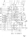
- a compressed air processing device 1 illustrated by a dash-dotted lines as a common unit, which has the various elements within a housing.
- the outline of the compressed air treatment device 1 can also be regarded as a housing.
- connection 2 is provided, to which a line 3 is introduced, which emanates from a compressor 4.
- the line 3 continues within a line 5 in the compressed air processing device 1, which leads on the one hand to an air dryer 6.
- a line 7 leads to a check valve 8, which in the usual way separates the part of the compressed air treatment device before the check valve 8 from the subsequent central ventilation 9.
- the central ventilation 9 can also be regarded as a common inflow space via which the individual circuits I to V are supplied.
- a line 10 leads to a safety valve 11, which output side is connected to a vent opening 12.
- a pressure regulator 13 is provided, the as recognizable having a blocking position and a passage position and of the force of a spring is acted upon in the blocking position, while on the other hand by a Solenoid valve is switched to the passage position according to the idling phase.
- a control valve 14 is provided, which via a line 15, the compressor 4 switches. Via the line 15, a clutch be switched on the compressor 4 or, for example, a the air promotion in Compressor 4 can be influenced.
- the control valve 14 is from the central ventilation 9 via a line 16 supplied with compressed air.
- a supply line 17 From the central ventilation 9 and a common inflow leads a supply line 17 to a controlled overflow valve 18 which is associated with the circuit I.
- the supply line 19 On the output side, the supply line 19 is provided, which ultimately has a connection and a corresponding line to a reservoir 20 of the circuit I leads.
- the circle II is trained accordingly.
- a supply line 21 here controlled spill valve 22 and a supply line 23 to the associated Reservoir 24.
- the reservoir 20 and 24 are the two service brake circuits assigned and can be designed or determined for a pressure of 12 bar.
- the controlled spill valve 18 is initially as each spill valve with limited Built back flow, d. H. it has on the inflow side a first effective area and downstream a second effective area, so that between opening and closing pressure the usual Hysteresis arises.
- the overflow valve 18 but also a third and a fourth effective area, wherein the third effective area pneumatically via a solenoid valve 25th is controlled and used to open the spill valve 18.
- the fourth effective area is controlled by a solenoid valve 26 and serves to reach the closed position of the Overflow valve 18.
- the solenoid valves 25 and 26 also control the overflow valve 22 with its third and fourth effective area accordingly.
- the compressed air supply of Solenoid valves 25 and 26 via a line 27, which also connects to Central ventilation 9 has.
- a pressure sensor 28 detects the pressure in the supply line 19 and thus in the reservoir 20 and outputs a corresponding voltage signal via a not shown line to a control electronics 29. It is understood that of the Control electronics 29 and corresponding electrical control lines not shown to the other elements, for example, to the solenoid valves 25 and 26 are performed.
- solenoid valve 30 is provided, which, as shown, the two switching positions has, is controlled by the control electronics 29 and in turn the pressure regulator 13 as also controls the control valve 14 pneumatically.
- a Regeneration valve 31 driven, ie together with the third effective area of the Overflow valves 18 and 22.
- the regeneration valve 31 is in a bypass line 32nd arranged, which bridges the check valve 8 and thus a return flow between the central ventilation 9 and the line 7 backwards through the air dryer. 6 allows.
- the circle III has a supply line 33 which from the central ventilation. 9 goes out and leads to an overflow valve 34, which, however, only three active surfaces having.
- a solenoid valve 35th intended to set an open position of the overflow valve 34.
- From the spill valve 34 leads a supply line 36 to the circle III, the shown here saving a reservoir.
- a pressure limiter 37 included in the supply line 36 , which upon reaching a set pressure, For example, 8.5 bar, goes into the closed position.
- a set pressure For example, 8.5 bar, goes into the closed position.
- the trailer is supplied with compressed air.
- From the supply line 36 branches one Supply line 38, which is assigned to the supply of the handbrake.
- a check valve 39 installed in the direction shown.
- a safety valve 40 leads via a line 41 to a vent port 42.
- a supply line 43 which leads to a Overflow valve 44 with downstream pressure limiter 45 leads.
- a supply line 46 is associated with the circle IV, may be connected to the auxiliary consumer, the require a pressure of 10 bar for their operation.
- the overflow valves 18, 22, 34 and 44 are components of a multi-circuit protection valve 47 and thus a first control group 48, which summarizes the circles I to IV. It can be seen that the two Service brake circuits I and II with the highest pressure within the control group 48 be supplied, namely with 12 bar.
- the circle V forms a second control group 49.
- a supply line 50 from which to a spill valve 51 and a downstream check valve 52 leads. She sits down in a supply line 53 continues, which ultimately leads to a reservoir 54 of the circle V.
- the circle V is used for Supplying an air spring system of the motor vehicle and may to a supply pressure of Be set 15 bar.
- the second control group 49 is definitely the group that includes the maximum pressure compared to all existing supply pressures or having.
- the output side pressures of the various circuits are determined by pressure sensors supervised.
- a pressure sensor 55 is provided and connected in the appropriate manner.
- One Pressure sensor 56 monitors the output pressure in the supply line 36 of the circle III.
- a pressure sensor 57 monitors the pressure in the supply line 53 and the Reservoir 54 of the circle V. All pressure sensors 28, 55, 56, 57 are by electrical Lines connected to the control electronics 29, so that the pressure corresponding Voltage signals are processed.
- the plant according to FIG. 1 is operated as follows:
- the elements are in the illustrated positions.
- the pressure in the reservoirs 20 and 24, for example 7 bar, which of the pressure sensors 28 and 55 to the control electronics 29th is reported.
- the solenoid valve 25 is turned off and the solenoid valve 35th driven.
- the Overflow valves 18 and 22 transferred to the closed position. This is done by means of a Switching pulse via the solenoid valve 26 and the fourth effective surface of the overflow valves 18 and 22. It is followed by a further pressure increase in the container 54, which with the Reaching the intended pressure of 15 bar for the air suspension to find its conclusion can. This is reported to the control electronics 29 via the sensor 57. It follows Switching the solenoid valve 30. As a result, the pressure regulator 13 in his Passed passage position, so that the idle phase is turned on and the Compressor 4 promotes through the vent port 12 into the atmosphere. In parallel the control valve 14 is switched so that a pressure pulse, the promotion of the compressor 4 interrupts. The solenoid valve 26 is turned off, so that the overflow in their normal open position can return and an air exchange between the Circles I to IV becomes possible.
- the journey begins. While driving occurs in the wake of braking a compressed air consumption in the circles I and II, so that the pressure in the reservoirs 20 and 24 decreases, while in the other circles, especially in circuit V, no compressed air consumption may occur.
- the solenoid valve 30 is switched again.
- the pressure regulator 13 and the control valve 14 change their again Positions, so that the compressor 4 in turn promotes compressed air, via the check valve 8 passes into the central ventilation 9.
- the compressed air passes over the overflow valves 18 and 22, which are in their normal open position, into the reservoirs 20 and 24, until the intended pressure of 12 bar is reached again.
- the pressure sensors 28 and 55 monitor these pressures and report reaching the control electronics 29, so that As a result, the pressure regulator 13 and the control valve 14 are switched again, so that the compressor 4 stops its promotion. The same applies to air consumption in circles III and IV. Also in this case, the compressor 4 with maximum 12 bar. The compressor 4 is spared during these phases, resulting in in a long life.
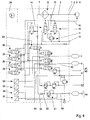
- the compressed air treatment plant shown in Fig. 2 is formed in many areas similar to the system of FIG. 1, which is why the local description can be referenced. All details regarding the control group 48 are unchanged. Again, only the circle V is detected in the control group 49.
- a check valve 58 is arranged here, which, as can be seen, has a blocking position and a passage position. In de-energized state, the blocking position is switched by a spring 59.
- the solenoid valve 26 not only switches the two overflow valves 18 and 22 in the closed position, but also switches the check valve 58 in the passage position.
- a separate electrically controllable solenoid valve in the supply line 50, 53 may be provided, which is controlled directly via the control electronics 29.
- the check valve 58 also fulfills the function of the check valve 52 of the system according to FIG. 1, ie, in the blocking position, a return flow and an exchange of compressed air to the overflow valves of the control group 48 is prevented.
- a switching valve 60 is used to form the two control groups 48 and 49, which is arranged at the beginning of the central ventilation 9 immediately after the check valve 8.
- the changeover valve 60 has two positions by once connecting the control group 48 and completing the control group 49 and vice versa. It suffices here the arrangement of the solenoid valves 30, 25 and 26 and the pressure sensors 28, 55 and 57.
- the overflow valves 18 and 22 have here only three active surfaces.
- the pressure limiter 37 is here jointly assigned to the circles III and IV and arranged in front of the respective overflow valves 34 and 44.
- In the supply line 50, 53 which has from the central ventilation 9 via a line 61 connection in the relevant position of the change-over valve 60 to the central ventilation 9, no switching element is arranged.
- a line 62 leads from the switching valve 60 to the elements of the circles I to IV and the multi-circuit protection valve 47. It can be seen how switching the changeover valve 60, which takes place via the solenoid valve 26, but also directly from the control electronics 29 can be operated, either only the control group 48 or the control group 49. Accordingly, the load running phase of the compressor 4 is set and performed. Since it is also to be expected here with the essential compressed air consumption in the area of circles I and II, the compressor 4 is operated at this comparatively lower pressure level. Only now and then must the container 54 be filled with the maximum pressure.
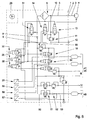
- FIG. 4 The embodiment of FIG. 4 follows the embodiments described above.
- a switching valve 63 is provided at the beginning of the central ventilation.
- the switching valve 63 has two positions, as shown. In one position only the line 61 is operated, in the other position, the lines 61 and 62 are connected simultaneously. In this case, in the supply line 50, 53 of the circuit V, the arrangement of the overflow valve 51 and the check valve 52 is required.
- the check valve 52 is arranged upstream of the overflow valve 51 here. In this way, again, the two control groups 48 and 49 are formed. Again, the control group 48, the four circles I, II, III and IV, while the second control group also has only the circle V.
- control group 48 is designed to omit the supply of the maximum pressure and to be directed substantially to the highest occurring pressure within the circles grouped together by the control group 48, while the second control group 49 in any case comprises the circle which is the maximum Pressure has. However, it is also possible to group several circles in the area of the control group 49.
- the system according to FIG. 5 has a check valve 64, which on the one hand takes the place of the changeover valves 60 and 63 and on the other hand performs the function of the blocking position of the overflow valves 18 and 22 of the system according to FIG. Again, it is necessary to form the control group 49 in the supply line 50, 53, a spill valve 51 and a check valve 52, in any order to arrange.
- the circle III and the circle IV are constructed here again in accordance with the embodiment of FIG.
- FIG. 6 has the special feature that the two overflow valves 18 and 22 of the circles I and II, a common pressure limiter 65 is connected upstream.
- the system is otherwise constructed as already shown in FIG. 5.
- the two control groups 48 and 49 are formed, by the spill valve 51 and the check valve 52.
- the solenoid valve 26 can be omitted here.
- the operation of the compressor 4 to form the two control groups 48 and 49 is manageable from the foregoing.
- the control group 49 has only one circle, it is easy to imagine that the control group can also identify multiple circles, as shown for the control group 48.
Abstract
Description
Die Erfindung bezieht sich auf ein Verfahren zum Betreiben einer Druckluftbeschaffungsanlage
eines Kraftfahrzeuges sowie Druckluftaufbereitungseinrichtung mit den in den Oberbegriffen
der Ansprüche 1 und 5 angegebenen Merkmalen. Eine Druckluftbeschaffungsanlage
weist eine Druckluftaufbereitungseinrichtung und einen Kompressor sowie den
einzelnen Verbraucherkreisen zugeordnete Vorratsbehälter für Druckluft bestimmter Druckhöhe
auf. Die Druckluftaufbereitungseinrichtung weist einen Druckregler, in der Regel auch
einen Lufttrockner, ein Mehrkreisschutzventil und eine Steuerelektronik auf. Je nach
Ausführungsform sind diese Teile zu einer gemeinsamen Baueinheit zusammengefügt. Eine
solche gemeinsame Baueinheit kann beispielsweise als Druckluftaufbereitungseinrichtung
dem Kompressor einer Druckluftbeschaffungseinrichtung nachgeschaltet sein.The invention relates to a method for operating a compressed air procurement system
of a motor vehicle and compressed air treatment device with those in the preambles
of
Eine Druckluftaufbereitungseinrichtung der in Rede stehenden Art ist aus der DE 44 21 575
C2 bekannt. Hierbei sind ein Druckregler, ein Lufttrockner, ein Mehrkreisschutzventil und
eine Steuerelektronik zu einer gemeinsamen Baueinheit zusammengefügt. Innerhalb der
gemeinsamen Baueinheit sind den einzelnen Verbraucherkreisen zugeordnete mechanisch-pneumatische
Ventile, insbesondere Überströmventile, Druckbegrenzer, Schaltventile
und/oder Rückschlagventile und dgl. vorgesehen. Für die Erfassung der ausgangsseitigen
Drücke in den Kreisen I bis IV sind Drucksensoren vorgesehen, deren Signale der Steuerelektronik
zugeleitet werden. Alle Kreise werden gleichwertig bzw. gleichrangig behandelt.
Die Kreise können durch die Überströmventile mit begrenzter Rückströmung abgesichert
sein. Hierbei ist jedem Überströmventil jedes Kreises ein Magnetventil zugeordnet. Das
Magnetventil ist in nicht erregtem Zustand offen, d. h. der Federraum des Überströmventils
ist mit dem Anströmraum verbunden. Damit besitzt das Überströmventil einen vergleichsweise
erhöhten Öffnungsdruck. In erregtem Zustand schaltet das Magnetventil um und
entlüftet den Federraum. Damit ist eine Zuhalten der Überströmventile und eine gezieltes
Öffnen der Überströmventile durch Freigabe der normalen Funktion eines Überströmventils
mit seinen zwei Wirkflächen möglich. Die Absicherung kann aber auch durch vorgesteuerte
Rückschlagventile erfolgen, die durch einen über ein Magnetventil zu schaltenden
Betätigungskolben aufgestoßen werden können.A compressed air treatment device of the type in question is known from
An einen fünften Verbraucherkreis V kann die Luftfederung des Fahrzeugs angeschlossen sein. In der Versorgungsleitung zu einem Vorratsbehälter dieses Kreises ist ein Überströmventil mit begrenzter Rückströmung ohne Vorsteuerung angeschlossen. Das Überströmventil ist damit Bestandteil des Mehrkreisschutzventils. Es lässt in seiner Offenstellung einen Luftaustausch mit den übrigen Kreisen zu. Die Luftfederung kann aber auch an den Kreis IV angeschlossen sein, der in Übereinstimmung mit dem Aufbau der Kreise I bis III aufgebaut ist. Der Kreis V wird auch für die Regeneration genutzt. Über eine Steuerelektronik werden alle Kreise gemeinsam je dach dem Luftverbrauch in einem der Kreise gesteuert. Der Druckregler mit dem zugehörigen Auslassventil wird in gleicher Weise gesteuert, unabhängig davon in welchem Kreis ein Luftverbrauch aufgetreten ist. Dies ist unschädlich für die Lebensdauer des Kompressors, solange der Vorratsdruck im Kreis V eine Druckhöhe aufweist, die der Druckhöhe der übrigen Kreise entspricht.To a fifth consumer circuit V, the air suspension of the vehicle can be connected be. In the supply line to a reservoir of this circuit is a spill valve connected with limited return flow without pilot control. The overflow valve is thus part of the multi-circuit protection valve. It leaves one in its open position Air exchange with the other circles too. The air suspension can also be to the circle IV connected in accordance with the structure of the circles I to III is. The circle V is also used for regeneration. Be via a control electronics all circles are controlled together according to the air consumption in one of the circles. Of the Pressure regulator with the associated outlet valve is controlled in the same way, independently of which circle an air consumption has occurred. This is harmless for the Life of the compressor, as long as the supply pressure in the circle V is a pressure level which corresponds to the pressure level of the other circles.
Wenn jedoch die Luftfederung des Kraftfahrzeuges eine vergleichsweise höhere Druckhöhe als z. B. die der Betriebsbremse zugeordneten Kreise I und II erfordert, muss das Überströmventil des Kreises V entsprechend hoch eingestellt werden. Dann aber wird bei jedem Luftverbrauch in den Kreisen I und II durch den zugelassenen Luftaustausch bzw. das Nachfüllen der Kreise I und II aus dem Kreis V heraus sich eine Absenkung der Druckhöhe im Kreis V einstellen, auch wenn im Kreis V kein eigener Luftverbrauch vorliegt, weil der Aufbau des Kraftfahrzeuges während der Fahrt weder gehoben wurde, noch eine Beladung stattgefunden hat. Der Kompressor muss also in jeder Lastlaufphase gegen den sehr hohen, in der Regel maximalen, Druck im Kreis V arbeiten und diesen bereitstellen. Dies verkürzt die Lebensdauer des Kompressors erheblich. However, if the air suspension of the motor vehicle has a comparatively higher pressure level as z. B. requires the service brake associated circuits I and II, the spill valve must of the circle V are set accordingly high. But then everyone will Air consumption in Circles I and II by the authorized air exchange or the Refilling the circles I and II out of the circle V out a lowering of the pressure level set in circuit V, even if there is no separate air consumption in circuit V, because the Structure of the vehicle while the ride was neither lifted, nor a load took place. The compressor must therefore be in every load phase against the very high, usually maximum pressure to work in circle V and deploy this. This shortens the life of the compressor considerably.
Eine ähnliche Druckluftaufbereitungseinrichtung einer Druckluftbeschaffungsanlage ist auch aus der DE 195 44 621 C1 bekannt. In einem gemeinsamen Gehäuse, welches auch unterteilt ausgebildet sein kann, ist ein Druckregler, ein Lufttrockner, ein Mehrkreisschutzventil und eine Steuerelektronik mit ihren entsprechenden Elementen untergebracht. Das Mehrkreisschutzventil ist für alle Kreise ausgebildet und angeordnet, die von dem Gehäuse abzweigen. Jeder Kreis besitzt ein Überströmventil mit begrenzter Rückströmung. Bei aufgefüllter Anlage stehen die Überströmventile offen, sodass ein Luftaustausch möglich ist. An einen Kreis V kann die Luftfederung angeschlossen sein. Der Kreis V wird auch zur Regeneration des Lufttrockners genutzt. Über den Luftverbrauch wird der Druckregler und damit der Leerlauf/Lastlaufzyklus des Kompressors gesteuert. Es treten dieselben Nachteile, wie oben beschrieben auf.A similar compressed air treatment device of a compressed air procurement system is also known from DE 195 44 621 C1. In a common housing, which too may be formed divided, is a pressure regulator, an air dryer, a multi-circuit protection valve and a control electronics housed with their corresponding elements. The multi-circuit protection valve is designed and arranged for all circles, which of the Branch housing. Each circuit has an overflow valve with limited backflow. When the system is filled up, the overflow valves are open so that an air exchange is possible is. To a circle V, the air suspension can be connected. The circle V is also the Regeneration of the air dryer used. About the air consumption is the pressure regulator and thus controlling the idle / load cycle of the compressor. There are the same disadvantages as described above.
Eine weitere Druckluftaufbereitungseinrichtung ist aus der DE 197 00 243 C1 bekannt. Hier ist einem Überströmventil ein Druckbegrenzer vor- oder nachgeschaltet, der über ein Magnetventil vorgesteuert wird. Die Druckregelung erfolgt gemeinsam über die Steuerelektronik für alle Kreise.Another compressed air treatment device is known from DE 197 00 243 C1. Here an overflow valve is a pressure limiter upstream or downstream, via a Solenoid valve is piloted. The pressure is controlled jointly via the control electronics for all circles.
Die DE 195 15 895 A1 zeigt eine Druckluftaufbereitungseinrichtung mit einem Druckregler, einem Lufttrockner und einem integrierten Mehrkreisschutzventil. In der Füllleitung ist dem Lufttrockner das übliche Rückschlagventil nachgeschaltet, an dem die Zentralbelüftung beginnt, über die die Überströmventile der einzelnen Kreise mit Druckluft versorgt werden. In einer ersten Ausführungsform sind den Überströmventilen vorsteuernde Magnetventile vorgeschaltet. Über Magnetventile können auch den Überströmventilen nachgeschaltete Sperrventile geschalt werden. In einer dritten Ausführungsform können die Überströmventile und die Magnetventile durch über eine Steuerelektronik direkt steuerbare Sperrventile ersetzt sein. In den meisten Kreisen werden die ausgangsseitigen Drücke durch Drucksensoren erfasst, deren Signale an die Steuerelektronik weitergeleitet werden. Damit ist es möglich, druckabhängig auf die Befüllung der einzelnen Kreise Einfluss zu nehmen. Bevorzugte Befüllung ist erreichbar. Zum Füllen des der Luftfederung zugeordneten Kreises V auf einen gegenüber den anderen Kreisen I bis IV erhöhten Druck werden die Überströmventile der anderen Kreise oder die Sperrventile in die Sperrstellung überführt. Durch die an die Kreise I bis V angeschlossenen Verbraucher wird Druckluft in unterschiedlichem Ausmaß verbraucht. Der Kreis V kann von einem Luftaustausch ausgeschlossen werden, ebenso andere Kreise. Jeder Kreis wird einzeln behandelt. Damit jeder Kreis einzeln behandelt werden kann, ist es notwendig, jeden Kreis mit einem eigenen Vorratsbehälter auszustatten. Dadurch entsteht ein entsprechender Aufwand. Wenn ein Druckluftverbrauch in einem Kreis stattfindet, wird dies von der Steuerelektronik erkannt und es schließt sich ein Nachfüllen dieses Kreises an. Durch entsprechende Programmierung der Steuerelektronik kann die Erstbefüllung, die Aufeinanderfolge der Befüllung der Kreise, die Einstellung unterschiedlicher Betriebsdrücke, der Ausgleich unterschiedlichen Druckluftverbrauchs in den Kreisen sowie das Wiederauffüllens der Kreise in weiten Grenzen variiert werden. Durch entsprechende Programmierung der Steuerelektronik kann die Arbeitsweise des Kompressors gesteuert werden. Es kann die kinetische Energie des Fahrzeugs im Schiebebetrieb genutzt werden, um einen Kreis auf ein höheres Druckniveau aufzufüllen als es dem Betriebsdruck dieses Kreises entspricht. Durch Luftaustausch mit diesem Kreis kann ein anderer Kreis bedient werden. Durch die Einzelsteuerung jedes Kreises und den Einsatz elektronischer Mittel für jeden einzelnen Steuerungsvorgang erhöht sich die Anzahl der Schaltungen erheblich. Dies ist nachteilig für die Lebensdauer der Überströmventile, Sperrventile und der Magnetventile. Die Einzelsteuerung erhöht auch in nachteiliger Weise die Schalthäufigkeit des Druckreglers und die Anzahl der Schaltungen des Lastlauf/Leerlaufzyklusses und damit die Lebensdauer des Kompressors. Bei Ausfall der oder einem Defekt in der Spannungsversorgung der Steuerelektronik ergibt sich ein Totalausfall der Druckluftaufbereitungseinrichtung und der Druckluftbeschaffungsanlage. Ist ein Luftaustausch zwischen einzelnen oder allen Kreisen beabsichtigt, so müssen hierzu die betreffenden Sperrventile der Kreise geöffnet werden. Dann aber geht gespeicherte Druckluft über die das Rückschlagventil vor der Zentralbelüftung überbrückende Leitung mit Drossel verloren, zumindest während einer Leerlaufphase, obwohl zu diesem Zeitpunkt eine Regeneration nicht beabsichtigt ist. Weiterhin ist nachteilig, dass bei Spannungsausfall, sei es infolge eines eintretenden Defektes oder durch Ausschalten der Zündung des Kraftfahrzeuges, alle angeschlossenen Kreise bis auf den Schließdruck der Überströmventile entleert werden. Die notwendige Wiederbefüllung erfordert zusätzliche Kompressorarbeit.DE 195 15 895 A1 shows a compressed air treatment device with a pressure regulator, an air dryer and an integrated multi-circuit protection valve. In the filling line is the Air dryer downstream of the usual check valve, where the central ventilation begins, over which the relief valves of the individual circuits are supplied with compressed air. In In a first embodiment, the overflow valves are pilot-controlling solenoid valves upstream. Solenoid valves can also be used downstream of the overflow valves Shut-off valves are switched. In a third embodiment, the overflow valves and the solenoid valves replaced by over a control electronics directly controllable shut-off valves be. In most circles, the output pressures are measured by pressure sensors detected, whose signals are forwarded to the control electronics. This makes it possible pressure-dependent on the filling of the individual circles influence. preferred Filling is achievable. To fill the air suspension associated circle V on a compared to the other circuits I to IV increased pressure, the overflow valves other circles or the check valves transferred to the locked position. By the to the circles I Up to V connected consumers, compressed air is consumed to varying degrees. The circle V can be excluded from an air exchange, as well as other circles. Each circle is treated individually. So that each circle can be treated individually, it is necessary to equip each circuit with its own storage tank. This creates a corresponding expense. When a compressed air consumption takes place in a circle, is this is detected by the control electronics and it is followed by refilling this circuit. By appropriate programming of the control electronics, the Erstbefüllung, the Sequence of filling the circles, setting different operating pressures, the compensation of different compressed air consumption in the circles as well as the Refilling the circles can be varied within wide limits. By appropriate Programming the control electronics can control the operation of the compressor become. The kinetic energy of the vehicle can be used in push mode, to fill a circle to a higher pressure level than the operating pressure of this Circle corresponds. By air exchange with this circle another circle can be served become. Through the individual control of each circuit and the use of electronic means for every single control process increases the number of circuits considerably. This is detrimental to the life of the overflow valves, check valves and the solenoid valves. The individual control also adversely increases the switching frequency of the pressure regulator and the number of circuits of the load / idle cycle and thus the life of the compressor. In case of failure of or a defect in the power supply of Control electronics results in a total failure of the compressed air processing device and the Compressed air system. Is an air exchange between individual or all circles intended, it must be opened for this purpose the relevant check valves of the circles. But then stored compressed air goes over the check valve in front of the Central ventilation bridging line with choke lost, at least during one Idle phase, although at this time a regeneration is not intended. Another disadvantage is that in case of power failure, either as a result of an incoming Defective or by switching off the ignition of the motor vehicle, all connected Circles are emptied to the closing pressure of the overflow valves. The necessary Refilling requires additional compressor work.
Der Erfindung liegt die Aufgabe zugrunde, ein Verfahren zum Betreiben einer Druckluftbeschaffungsanlage sowie eine solche Druckluftbeschaffungsanlage bereitzustellen, die Kreise mit unterschiedlichen Druckhöhen hat und bei der der Kompressor bei Luftverbrauch in Kreisen mit nicht maximaler Druckhöhe nicht gegen den maximalen Druck fördern muss. The invention is based on the object, a method for operating a compressed air procurement system and to provide such a compressed air procurement system, the Circles with different pressure levels and at which the compressor has air consumption in circles with non-maximum pressure, does not have to promote against the maximum pressure.
Die Anzahl der elektrisch von der Steuerelektronik generierten Schaltungen für die Überströmventile, Sperrventile und dergleichen sollen möglichst gering gehalten werden, um die Lebensdauer der Druckluftbeschaffungsanlage und der Druckluftaufbereitungseinrichtung hoch zu halten.The number of electrically generated by the control electronics circuits for the Overflow valves, check valves and the like should be kept as low as possible in order to the life of the compressed air supply system and the compressed air preparation device to hold up.
Erfindungsgemäß wird dies bei einem Verfahren zum Betreiben einer einen Kompressor,
einen Druckregler, ein Mehrkreisschutzventil aufweisenden Druckluftbeschaffungsanlage mit
den im Oberbegriff des Anspruches 1 angegebenen Merkmalen dadurch erreicht, dass die
mehreren Verbraucherkreise mit den unterschiedlichen Druckhöhen steuerungstechnisch in
mindestens zwei Steuerungsgruppen unterteilt bzw. zusammengefasst werden, von denen
die eine Steuerungsgruppe den Kreis mit der maximalen Druckhöhe umfasst oder aufweist,
während die andere Steuerungsgruppe den Kreis mit der minimalen Druckhöhe umfasst oder
aufweist. Der Kompressor wird zwischen Leerlaufphase und Lastlaufphase über den
Druckregler und ein zugehöriges Auslassventil von einem von der Steuerelektronik
generierten Signal entsprechend dem Luftverbrauch in den beiden gebildeten Steuerungsgruppen
geschaltet.According to the invention, this is achieved in a method for operating a compressor,
a pressure regulator, a multi-circuit protection valve having compressed air procurement system with
the features specified in the preamble of
Während bisher alle Kreise auch dann, wenn sie unterschiedliche Druckhöhen in den einzelnen Vorratsbehältern der Kreise vorsahen, über die Zentralbelüftung nach dem Rückschlagventil einheitlich als eine Steuerungsgruppe oder in Einzelsteuerung behandelt wurden und nur durch Überströmventile, Druckbegrenzer, Schaltventile und dergleichen unterschieden wurden, sieht die neue Erfindung vor, an der beschriebenen Stelle mindestens zwei Steuerungsgruppen zu bilden, die in unterschiedlicher Weise Einfluss auf die Steuerung des Druckreglers und dann auch des Kompressors nehmen. Die eine Steuerungsgruppe umfasst auf jeden Fall den Kreis, in welchem die maximale Druckhöhe vorrätig gehalten werden muss. Bei diesem Kreis kann es sich insbesondere um die Versorgung einer Luftfederung des Kraftfahrzeugs handeln, wobei die Druckhöhe insbesondere in der Größenordnung von 12 bis 15 bar liegen kann. Es ist ohne weiteres möglich, dass diese Steuerungsgruppe nur diesen einen Kreis V aufweist. In einem solchen Falle umfasst die andere Steuerungsgruppe die Betriebsbremskreise der Kreise I und II, den Kreis III zur Versorgung der Anhängerbremse sowie der Feststellbremse und den Kreis IV zur Versorgung der Nebenverbraucher. In den Betriebsbremskreisen kann ein Druck von 12 bar gewünscht bzw. festgelegt sein. Der Kreis III kann 8,5 bar aufweisen. Die Nebenverbraucher am Kreis IV können beispielsweise 10 bar erfordern. In der Regel genügt eine Unterteilung der einzelnen Kreise in zwei Steuerungsgruppen, wie beschrieben. Es ist jedoch auch möglich, mehr als zwei Steuerungsgruppen zu bilden, um bereichsweise eine noch weitergehendere Unterteilung zu bekommen. Sinn der Bildung dieser Steuerungsgruppen ist es, den Kompressor unterschiedlich zu betreiben, je nach dem, in welchem der Kreise der Steuerungsgruppen ein Luftverbrauch anfällt. So genügt es in vielen Fällen, die maximale Druckhöhe von z. B. 15 bar in dem Vorratsbehälter des Kreises V vor oder bei Antritt einer Fahrt einmalig zur Verfügung zu stellen und abzuspeichern. Der Kompressor muss also für diese eine Fahrt nur einmal gegen diesen hohen Druck von 15 bar arbeiten. Während der Fahrt möge kein Luftverbrauch an der Luftfeder eintreten, sondern nur der übliche Luftverbrauch zum Betätigen der Bremsen und der Nebenverbraucher. In diesem Falle wird also der Kompressor hinsichtlich seiner Lastlaufphase und Leerlaufphase so gesteuert, dass er während der Fahrt maximal gegen einen Druck von 12 bar der Kreise I und II arbeiten muss. Der höchste Druck in den Kreisen, die durch die Steuergruppe gebildet wird, die den maximalen Druck nicht umfasst, steuert in diesem Fall den Druckregler und damit den Kompressor, wobei durch Überströmventile mit begrenzter Rückströmung sichergestellt ist, dass alle Kreise dieser Steuerungsgruppe bedient werden. Es ist aber auch möglich, sämtliche Kreise dieser Steuerungsgruppe durch je einen Drucksensor in der jeweiligen zu einem Vorratsbehälter führenden Versorgungsleitung zu überwachen und aus den Signalen dieser Drucksensoren Einfluss auf die Steuerung des Druckreglers zu nehmen. Innerhalb jeder Steuerungsgruppe, die mehr als einen Kreis aufweist, ist ein Luftaustausch möglich.While so far all circles even if they have different pressure levels in the individual reservoirs of the circles provided, via the central ventilation after the Check valve uniformly treated as a control group or in individual control and only by overflow valves, pressure limiters, switching valves and the like were distinguished, the new invention provides, at the described location at least two steering groups, which influence each other in different ways take the control of the pressure regulator and then also of the compressor. The one Control group includes in any case the circle in which the maximum pressure level must be kept in stock. This circle may be in particular the Supply an air suspension of the motor vehicle act, the pressure level especially in the order of 12 to 15 bar can be. It is easy possible that this control group has only this one circle V. In such a Case, the other control group comprises the service brake circuits of circuits I and II, Circuit III to supply the trailer brake and the parking brake and the circle IV for the supply of secondary consumers. In the service brake circuits, a pressure of 12 bar desired or fixed. The circle III can have 8.5 bar. The secondary consumers For example, at circuit IV, 10 bar may be required. Usually one is enough Division of the individual circles into two control groups as described. However, it is It is also possible to form more than two steering groups, in some areas one more to get more detailed subdivision. Sense of formation of these steering groups is to operate the compressor differently, depending on which of the circles of the Control groups an air consumption is incurred. So it is sufficient in many cases, the maximum Pressure level of z. B. 15 bar in the reservoir of the circle V before or at the onset of a Ride once to provide and save. So the compressor has to be for this one ride only work against this high pressure of 15 bar once. During the Let no air consumption on the air spring occur, but only the usual Air consumption for operating the brakes and the secondary consumers. In this case will So the compressor in terms of its load phase and idle phase controlled so that While working, he works against a maximum pressure of 12 bar of circles I and II got to. The highest pressure in the circles formed by the control group that the does not include the maximum pressure, in this case controls the pressure regulator and thus the Compressor, which is ensured by overflow valves with limited backflow, that all circuits of this control group are served. But it is also possible all circuits of this control group by a respective pressure sensor in the respective to monitor a reservoir leading supply line and from the signals These pressure sensors influence the control of the pressure regulator. Within each control group, which has more than one circle, an air exchange is possible.
Sinn dieser Betriebsweise ist es auch, die Anzahl der Schaltungen der Magnetventile, der Überströmventile oder sonstiger Betätigungselemente zu reduzieren, um damit die Langlebigkeit der Anlage zu fördern. Ein mehrfaches Hin- und Herschalten von Magnetventilen, Sperrventilen und dergleichen zum annäherungsweisen Erreichen eines entsprechenden Druckniveaus wird damit vermieden. Es ist auch beabsichtigt, die Anzahl der Schaltungen, die durch die Steuerelektronik ausgelöst werden, zu reduzieren, also in den einzelnen Steuergruppen, insbesondere in der Steuergruppe, die die minimale Druckhöhe umfasst, verlässlich arbeitende mechanisch-pneumatische Elemente zu belassen bzw. anzuordnen, die ohne elektronische Schaltimpulse zu erfordern eine Verteilung von Druckluft in unterschiedlichen Druckhöhen auf die einzelnen Kreise ermöglichen. Die mechanisch-pneumatischen Elemente erbringen auch bei Ausfall oder Defekt der Spannungsversorgung eine sinnvoll nutzbare Funktion.Sense of this operation, it is also the number of circuits of the solenoid valves, the Overflow valves or other actuators to reduce, so that the longevity to promote the plant. A multiple toggling of solenoid valves, Block valves and the like for approximatively reaching a corresponding Pressure levels is thus avoided. It is also intended to limit the number of circuits which are triggered by the control electronics to reduce, ie in the individual Control groups, in particular in the control group, which comprises the minimum pressure altitude, to maintain or arrange reliable mechanical-pneumatic elements, which without electronic switching pulses require a distribution of compressed air in allow different pressure levels on the individual circles. The mechanical-pneumatic Elements provide even in case of failure or failure of the power supply a useful function.
Um einen Luftaustausch zwischen mehreren zu einer Gruppe zusammengefassten Kreisen ohne Druckluftverlust zu ermöglichen, ist es bedeutsam, dass in der das Rückschlagventil vor der Zentralbelüftung überbrückenden Umgehungsleitung ein Regenerationsventil vorgesehen ist. Das Regenerationsventil sollte stromlos eine Sperrstellung einnehmen und nur zu Zwecken der Regeneration in eine Durchgangsstellung überführbar sein. Damit ist es möglich, dass eine Regeneration nur bei Bedarf auf Anforderung durch die Steuerelektronik stattfindet. Der gewollte Luftaustausch zwischen Kreisen einer Gruppe ist nicht zwangsläufig mit einem Luftverlust in die Atmosphäre verbunden. Bei Spannungsausfall, insbesondere bei abgestelltem Fahrzeug, wird ein Luftverlust bis auf den Schließdruck der Überströmventile sowie der vergleichsweise erhöhte Energiebedarf bei einer Wiederbefüllung der Kreise vermieden.To exchange air between several groups combined into a group Without allowing compressed air loss, it is significant that in the the check valve before the central ventilation bridging bypass a regeneration valve is provided. The regeneration valve should take a locked position without current and be transferable only for purposes of regeneration in a passage position. That's it possible that regeneration only when needed on request by the control electronics takes place. The desired air exchange between circles of a group is not inevitable associated with a loss of air into the atmosphere. In case of power failure, especially at parked vehicle, an air loss is up to the closing pressure of the overflow valves and the comparatively increased energy requirement when refilling the circuits avoided.
Die an den Ausgängen zu Vorratsbehältern der einzelnen Kreise anstehenden höchsten Drücke zumindest der Steuerungsgruppe mit der maximalen Druckhöhe und der Steuerungsgruppe mit der minimalen Druckhöhe werden jeweils gemessen und zur Steuerung des Lastund Leerlaufzyklus des Kompressors genutzt. Damit wird ein zugelassener Luftaustausch zwischen den Kreisen einer Steuerungsgruppe vorteilhaft genutzt. Auch der Bauaufwand erniedrigt sich, indem nicht mehr jeder Kreis mit je einem Drucksensor versehen sein muss.The highest at the exits to reservoirs of each circle pending Press at least the control group with the maximum pressure altitude and the control group with the minimum pressure altitude are respectively measured and used to control the load and Idle cycle of the compressor used. This will become an approved air exchange used advantageously between the circles of a steering group. Also the construction costs is reduced by no longer having to provide each circuit with a pressure sensor.
In der die minimale Druckhöhe umfassenden Steuergruppe von Kreisen erfolgt die Aufteilung der in der Lastlaufphase vom Kompressor geförderten Druckluft auf die einzelnen Kreise unter Einsatz von mechanisch-pneumatischen Ventilen, insbesondere von Überströmventilen, Druckbegrenzern, Schaltventilen und/oder Rückschlagventilen und dergleichen. Derartig mechanisch-pneumatische Ventile kommen mit wenigen Schaltimpulsen aus und besitzen große Zuverlässigkeit und Langlebigkeit.In the control group of circles comprising the minimum pressure level, the division takes place the compressed air delivered by the compressor in the load phase to the individual circuits using mechanical-pneumatic valves, in particular overflow valves, Pressure limiters, switching valves and / or check valves and the like. Such mechanical-pneumatic valves come with few switching pulses and possess great reliability and longevity.
Ein Luftaustausch zwischen der die maximale Druckhöhe umfassenden Steuerungsgruppe und der die minimale Druckhöhe umfassenden Steuerungsgruppe wird verhindert. Es ist also nicht beabsichtigt, einen Luftaustausch zwischen dem Kreis mit der maximalen Druckhöhe und den anderen Kreisen zuzulassen. Eine solche Steuerung würde einen Luftverbrauch in dem Kreis mit der maximalen Druckhöhe vortäuschen und damit wiederum dazu zwingen, den Kompressor erneut gegen die maximale Druckhöhe zu betreiben.An air exchange between the control group comprising the maximum pressure altitude and the control group comprising the minimum pressure level is prevented. So it is not intended to exchange air between the circle with the maximum head and the other circles. Such control would consume air in simulate the circle with the maximum pressure altitude, forcing it to to operate the compressor again against the maximum pressure level.
Die Druckluftaufbereitungseinrichtung ist Bestandteil einer Druckluftbeschaffungsanlage, die ihrerseits einen Kompressor aufweist. Die Druckluftaufbereitungseinrichtung weist einen Druckregler, einen Lufttrockner, ein Mehrkreisschutzventil und eine Steuerelektronik auf, die in einer gemeinsamen Baueinheit zusammengefasst sein können. Die Druckluftaufbereitungseinrichtung kann auch ein Regenerationsventil aufweisen. Innerhalb dieser gemeinsamen Baueinheit sind den einzelnen Kreisen zugeordnete mechanisch-pneumatische Ventile, insbesondere Überströmventile mit begrenzter Rückströmung, Druckbegrenzer, Schaltventile und/oder Rückschlagventile oder dergleichen vorgesehen. Erfindungsgemäß sind dabei die Kreise durch ein oder mehrere Elemente steuerungstechnisch in mindestens zwei Steuerungsgruppen unterteilt, von denen die eine Steuerungsgruppe den Kreis mit der maximalen Druckhöhe umfasst oder aufweist, während die andere Steuerungsgruppe den Kreis mit der minimalen Druckhöhe umfasst oder aufweist. Der Kompressor wird zwischen Leerlaufphase und Lastlaufphase über den Druckregler und ein zugehöriges Auslassventil von einem von der Steuerelektronik generierten Signal entsprechend dem Luftverbrauch in den beiden gebildeten Steuerungsgruppen geschaltet. Da der überwiegende Luftverbrauch während der Fahrt in den Kreisen I und II auftritt, die die Betriebsbremse versorgen, kann der Kompressor mit einem Abschaltdruck am Ende der Lastlaufphase betrieben werden, der niedriger liegt als der maximale Druck der Luftfederanlage. Dies schont den Kompressor und verbessert die Langlebigkeit der Elemente der Anlage. Freilich muss irgendwann auch der Vorratsbehälter mit der maximalen Druckhöhe aufgefüllt oder nachgefüllt werden. Dies geschieht jedoch in vergleichsweise größeren zeitlichen Abständen und nur bei Bedarf, so dass der normale Verschleiß des Kompressors begrenzt wird. In Verbindung damit wird der Kompressor in der Regel auf niedrigerem Druckniveau betrieben bzw. gehalten und ist an den Druckluftverbrauch in der Steuerungsgruppe von Kreisen angepasst, die die maximale Druckhöhe nicht aufweisen.The compressed air treatment device is part of a compressed air procurement system, the in turn, has a compressor. The compressed air processing device has a Pressure regulator, an air dryer, a multi-circuit protection valve and control electronics, the can be summarized in a common unit. The compressed air preparation device may also have a regeneration valve. Within this common Assembly are the individual circles associated mechanical-pneumatic Valves, in particular overflow valves with limited backflow, pressure limiters, Switching valves and / or check valves or the like provided. According to the invention are the circles by one or more elements control technology in at least divided two control groups, of which the one control group the circle with the maximum pressure level includes or has, while the other control group the Includes or has circle with the minimum pressure level. The compressor is between Idle phase and load phase via the pressure regulator and an associated exhaust valve from a signal generated by the control electronics according to the air consumption in switched the two control groups formed. Because the predominant air consumption occurs while driving in the circles I and II, which supply the service brake, the Compressor operated with a cut-off at the end of the load phase, the lower than the maximum pressure of the air spring system. This protects the compressor and improves the longevity of the elements of the plant. Of course, at some point, too Reservoir filled with the maximum pressure level or refilled. This However, this happens in comparatively larger time intervals and only when needed that the normal wear of the compressor is limited. In connection with it will be the Compressor is usually operated or held at a lower pressure level and is on adjusted the compressed air consumption in the control group of circles, which is the maximum Pressure level do not have.
Die Aufbereitungseinrichtung ist mit einem oder mehreren Elementen in einem oder mehreren der Kreise so ausgestattet, dass steuerungstechnisch mindestens zwei Steuerungsgruppen auf ganz verschiedene Art und Weise erreicht werden. Eine vergleichsweise einfache Ausführungsform entsteht dann, wenn die die steuerungstechnische Unterteilung bewirkende Elemente in der Versorgungsleitung des Kreises V, also des Kreises mit der maximalen Druckhöhe, ein Überströmventil mit begrenzter Rückströmung und ein Rückschlagventil sind. Die Reihenfolge dieser beiden Ventile in der Versorgungsleitung ist beliebig. Das Rückschlagventil ist so eingebaut, dass es auf jeden Fall einen Luftaustausch zu Kreisen der anderen Steuerungsgruppe verhindert. Das Rückschlagventil speichert die einmal erreichte maximale Druckhöhe in dem zugeordneten Vorratsbehälter verlässlich ab, so dass die dort gespeicherte Luft ausschließlich für diesen Zweck eingesetzt wird, nicht aber zum Luftaustausch.The processing device is with one or more elements in one or more several of the circuits are equipped so that control technology at least two control groups be achieved in a very different way. A comparatively simple embodiment arises when the control technology subdivision causing elements in the supply line of the circle V, so the circle with the maximum head, a relief valve with limited backflow and a Check valve are. The order of these two valves in the supply line is any. The check valve is installed so that there is definitely an air exchange prevented to circles of the other steering group. The check valve stores the Once reached maximum pressure level in the associated reservoir reliably, so that the air stored there is used exclusively for this purpose, not but for air exchange.
Es ist aber auch möglich, in der Versorgungsleitung, die von der Zentralbelüftung nach dem Rückschlagventil abzweigt, ein Sperrventil anzuordnen, welches eine Durchgangsstellung und eine Sperrstellung aufweist beispielsweise über ein elektrisch steuerbares Magnetventil angesteuert wird. Auch eine direkte Ansteuerung des Sperrventils über die Steuerungselektronik ist möglich. Dieses Sperrventil besitzt zweckmäßig auch eine mechanische Feder, die gewährleistet, dass das Sperrventil in stromlosem Zustand die Sperrstellung einnimmt.But it is also possible in the supply line, by the central ventilation after the Check valve branches, to arrange a check valve, which is a passage position and a blocking position has, for example via an electrically controllable solenoid valve is controlled. Also a direct control of the shut-off valve via the control electronics is possible. This check valve suitably also has a mechanical spring, which ensures that the check valve in de-energized state assumes the blocking position.
Eine etwas abweichende Gruppe von Lösungen sehen als Element zur Bildung der beiden Steuerungsgruppen gleichsam eine Weiche oder ein Umschaltventil vor, welches in der Zentralbelüftung dem dort vorgesehenen Rückschlagventil unmittelbar nachgeschaltet ist. Dieses Umschaltventil besitzt zwei Stellungen, von denen die eine wiederum aufgrund der Kraft einer mechanischen Feder eingenommen wird, während die andere beispielsweise durch ein Magnetventil vorgesteuert oder auch direkt von der Steuerelektronik gesteuert werden kann. Damit ergibt sich eine Verzweigungsmöglichkeit nach dem Rückschlagventil der Zentralbelüftung und es ist die Möglichkeit eröffnet, den Kompressor mit dem Druckregler gleichsam entweder an die eine Steuerungsgruppe oder an die andere Steuerungsgruppe anzuschließen und je nach dem den oder die Kreise der einen Steuerungsgruppe oder der anderen Steuerungsgruppe je nach Bedarf zu bedienen. Es versteht sich, dass auch die Schaltspanne des Druckreglers bzw. des Kompressors je nach den Anforderungen in der einen Steuerungsgruppe oder der anderen Steuerungsgruppe unterschiedlich gewählt bzw. vorgegeben wird. Die hierzu erforderlichen Maßnahmen können in der Steuerelektronik beinhaltet sein. Damit ergibt sich bei dieser Möglichkeit der besondere Vorteil, dass in der Steuerungsgruppe, die allein den Kreis V mit der maximalen Druckhöhe bedient, sämtliche mechanisch-pneumatischen Ventile, wie Überströmventile, Rückschlagventile und dergleichen, und auch elektrisch schaltbare Ventile, z.B. Magnetventile, in Fortfall kommen können. A slightly different set of solutions see as an element to the formation of the two Control groups as it were a switch or a diverter valve, which in the Central ventilation the check valve provided there is immediately downstream. This switching valve has two positions, one of which in turn due to the Force of a mechanical spring is taken, while the other example pre-controlled by a solenoid valve or directly controlled by the control electronics can be. This results in a branching possibility after the check valve the central ventilation and it opens the possibility to the compressor with the Pressure regulator as it either to one control group or the other Join the steering group and, depending on the circle or circles of the one Control group or the other control group as needed. It It is understood that also the switching range of the pressure regulator or the compressor depending on the requirements in the one control group or the other control group is chosen differently or specified. The necessary measures can be included in the control electronics. This results in this possibility of special advantage that in the control group, which alone the circle V with the maximum Pressure level, all mechanical-pneumatic valves, such as overflow valves, Check valves and the like, and also electrically switchable valves, e.g. Solenoid valves, can get lost.
Es ist aber auch möglich, das Umschaltventil bzw. die Weiche so auszubilden, dass in der einen Stellung nur die Steuerungsgruppe mit der maximalen Druckhöhe und in der anderen Stellung beide Steuerungsgruppen oder alle Steuerungsgruppen bedient bzw. versorgt werden. In diesem Falle muss dann wieder die Versorgungsleitung für den Kreis V mit entsprechenden Elementen versehen sein, insbesondere mit einem Überströmventil mit begrenzter Rückströmung und einem Rückschlagventil oder einem Überströmventil ohne Rückströmung. Die Steuerungsgruppe, die den maximalen Druck nicht umfasst, kann ansonsten im Vergleich zum Stand der Technik weitgehend unverändert ausgebildet werden, d. h. es können hier Überströmventile, Druckbegrenzer, Schaltventile, auch durch Magnetventile vorgesteuerte Schaltventile und dergleichen Anwendung finden. Die vorliegende Erfindung ist auch völlig unabhängig von einer Regeneration verwirklichbar, d. h. die Steuerung kann auch so ausgebildet bzw. auf eine erforderliche Regeneration des Lufttrockners abgestimmt und eingesetzt werden.But it is also possible, the switching valve or the switch in such a way that in the one position only the control group with the maximum pressure level and in the other Position both control groups or all control groups operated or supplied become. In this case, then again the supply line for the circle V with Be provided with appropriate elements, in particular with a spill valve with limited backflow and a check valve or overflow valve without Backflow. The control group that does not include the maximum pressure can otherwise be formed largely unchanged compared to the prior art, d. H. here can overflow valves, pressure limiters, switching valves, also by solenoid valves pilot operated switching valves and the like find application. The present Invention is also completely independent of regeneration feasible, d. H. the Control can also be designed or to a required regeneration of Air dryer are tuned and used.
Eine weitere Möglichkeit zur Bildung von zwei und mehr Steuerungsgruppen besteht darin, schaltbaren Überströmventilen der Kreise I und II beispielsweise ein gemeinsames Sperrventil vorzuordnen. Dieses Sperrventil weist eine Durchgangsstellung und eine Sperrstellung auf, ist durch eine mechanische Feder in die Durchgangsstellung beaufschlagt und kann z. B. elektrisch über ein Magnetventil vorgesteuert werden, um die Sperrstellung einzunehmen. Dies geschieht in Verbindung mit einem Überströmventil und einem Rückschlagventil in dem Kreis, der die maximale Druckhöhe aufweist.Another way of forming two or more steering groups is to switchable overflow valves of circuits I and II, for example, a common check valve vorzuordnen. This check valve has a passage position and a blocking position is acted upon by a mechanical spring in the passage position and can z. B. are electrically controlled by a solenoid valve to take the locked position. This is done in conjunction with an overflow valve and a check valve in the circle that has the maximum pressure altitude.
Das zuvor beschriebene Sperrventil kann auch durch einen Druckbegrenzer ersetzt sein, der den steuerbaren Überströmventilen der Kreise I und II vorgeschaltet ist. Sobald der eingestellte Druck am Druckbegrenzer erreicht bzw. überschritten wird, sind nicht nur die Kreise I und II, sondern auch die Kreise III und IV ordnungsgemäß aufgefüllt. Durch die Erfassung des Druckes ausgangsseitig am Kreis V wird über die Steuerelektronik ein Signal für die Schaltung des Druckreglers erzeugt bzw. unterdrückt, welches die Leerlaufphase des Kompressors einleitet.The check valve described above may also be replaced by a pressure limiter, the the controllable overflow valves of circuits I and II is connected upstream. As soon as the set pressure on the pressure limiter is reached or exceeded are not only the Circles I and II, but also the circles III and IV properly filled. By the Acquisition of the pressure on the output side of the circuit V is via the control electronics a signal generated or suppressed for the circuit of the pressure regulator, which is the idle phase of the Compressor initiates.
Die Erfindung wird anhand verschiedener Ausführungsbeispiele weiter erläutert und beschrieben. Es zeigen:
- Fig. 1
- eine erste Ausführungsform der Druckluftaufbereitungseinrichtung in Form eines Schaltplans,
- Fig. 2
- eine zweite Ausführungsform der Druckluftaufbereitungseinrichtung in Form eines Schaltplans,
- Fig. 3
- eine dritte Ausführungsform der Druckluftaufbereitungseinrichtung in Form eines Schaltplans,
- Fig. 4
- eine vierte Ausführungsform der Druckluftaufbereitungseinrichtung in Form eines Schaltplans,
- Fig. 5
- eine fünfte Ausführungsform der Druckluftaufbereitungseinrichtung in Form eines Schaltplans, und
- Fig. 6
- eine sechste Ausführungsform der Druckluftaufbereitungseinrichtung in Form eines Schaltplans.
- Fig. 1
- A first embodiment of the compressed air treatment device in the form of a circuit diagram,
- Fig. 2
- A second embodiment of the compressed air treatment device in the form of a circuit diagram,
- Fig. 3
- A third embodiment of the compressed air treatment device in the form of a circuit diagram,
- Fig. 4
- A fourth embodiment of the compressed air treatment device in the form of a circuit diagram,
- Fig. 5
- a fifth embodiment of the compressed air processing device in the form of a circuit diagram, and
- Fig. 6
- a sixth embodiment of the compressed air processing device in the form of a circuit diagram.
In dem in Fig. 1 dargestellten Schaltplan sind die wesentlichen Elemente durch Symbole
verdeutlicht. Es ist eine Druckluftaufbereitungseinrichtung 1 durch eine strichpunktierte
Linienführung als gemeinsame Baueinheit verdeutlicht, die innerhalb eines Gehäuses die
verschiedenen Elemente besitzt. Der Umriss der Druckluftaufbereitungseinrichtung 1 kann
auch als Gehäuse angesehen werden. Es ist dort ein Anschluss 2 vorgesehen, an den eine
Leitung 3 herangeführt ist, die von einem Kompressor 4 ausgeht. Die Leitung 3 setzt sich
innerhalb einer Leitung 5 in der Druckluftaufbereitungseinrichtung 1 fort, die einerseits zu
einem Lufttrockner 6 führt. Vom Lufttrockner 6 führt eine Leitung 7 zu einem Rückschlagventil
8, welches in üblicher Weise den Teil der Druckluftaufbereitungseinrichtung vor
dem Rückschlagventil 8 von der nachfolgenden Zentralbelüftung 9 trennt. Die Zentralbelüftung
9 kann auch als gemeinsamer Einströmraum angesehen werden, über den die
einzelnen Kreise I bis V versorgt werden. In the circuit diagram shown in Fig. 1 , the essential elements are illustrated by symbols. It is a compressed
Von der Leitung 5 führt eine Leitung 10 zu einem Sicherheitsventil 11, welches ausgangsseitig
an eine Entlüftungsöffnung 12 angeschlossen ist. Es ist ein Druckregler 13 vorgesehen,
der wie erkennbar eine Sperrstellung und eine Durchgangsstellung aufweist und von
der Kraft einer Feder in die Sperrstellung beaufschlagt ist, während er andererseits durch ein
Magnetventil in die Durchgangsstellung entsprechend der Leerlaufphase geschaltet wird. In
paralleler Ansteuerung zu dem Druckregler 13 ist ein Steuerventil 14 vorgesehen, welches
über eine Leitung 15 den Kompressor 4 schaltet. Über die Leitung 15 kann eine Kupplung
am Kompressor 4 geschaltet werden oder beispielsweise auch eine die Luftförderung im
Kompressor 4 beeinflusst werden. Das Steuerventil 14 wird aus der Zentralbelüftung 9 über
eine Leitung 16 mit Druckluft versorgt.From the
Von der Zentralbelüftung 9 bzw. einem gemeinsamen Einströmraum führt eine Versorgungsleitung
17 zu einem gesteuerten Überströmventil 18, welches dem Kreis I zugeordnet ist.
Ausgangsseitig ist die Versorgungsleitung 19 vorgesehen, die letztlich über einen Anschluss
und eine entsprechende Leitung zu einem Vorratsbehälter 20 des Kreises I führt. Der Kreis II
ist entsprechend ausgebildet. Es gibt hier ebenfalls eine Versorgungsleitung 21, ein
gesteuertes Überströmventil 22 und eine Versorgungsleitung 23 zu dem zugehörigen
Vorratsbehälter 24. Die Vorratsbehälter 20 und 24 sind den beiden Betriebsbremskreisen
zugeordnet und können für eine Druckhöhe von 12 bar ausgelegt bzw. bestimmt sein.From the
Das gesteuerte Überströmventil 18 ist zunächst wie jedes Überströmventil mit begrenzter
Rückströmung aufgebaut, d. h. es besitzt anströmseitig eine erste Wirkfläche und abströmseitig
eine zweite Wirkfläche, so dass zwischen Öffnungs- und Schließdruck die übliche
Hysterese entsteht. Darüber hinaus weist das Überströmventil 18 aber auch eine dritte und
eine vierte Wirkfläche auf, wobei die dritte Wirkfläche pneumatisch über ein Magnetventil 25
angesteuert wird und zum Öffnen des Überströmventils 18 dient. Die vierte Wirkfläche wird
über ein Magnetventil 26 angesteuert und dient zum Erreichen der Schließstellung des
Überströmventils 18. Die Magnetventile 25 und 26 steuern auch das Überströmventil 22 mit
dessen dritter und vierter Wirkfläche entsprechend an. Die Druckluftversorgung der
Magnetventile 25 und 26 erfolgt über eine Leitung 27, die ebenfalls Verbindung zur
Zentralbelüftung 9 hat. Ein Drucksensor 28 erfasst den Druck in der Versorgungsleitung 19
und damit im Vorratsbehälter 20 und gibt ein entsprechendes Spannungssignal über eine
nicht dargestellte Leitung an eine Steuerelektronik 29. Es versteht sich, dass von der
Steuerelektronik 29 auch entsprechende nicht dargestellte elektrische Steuerleitungen zu
den übrigen Elementen, beispielsweise auch zu den Magnetventilen 25 und 26 geführt sind.The controlled
Es ist ein Magnetventil 30 vorgesehen, welches, wie dargestellt, die beiden Schaltstellungen
besitzt, über die Steuerelektronik 29 angesteuert wird und seinerseits den Druckregler 13 wie
auch das Steuerventil 14 pneumatisch ansteuert. Über das Magnetventil 25 wird auch ein
Regenerationsventil 31 angesteuert, also gemeinsam mit der dritten Wirkfläche der
Überströmventile 18 und 22. Das Regenerationsventil 31 ist in einer Umgehungsleitung 32
angeordnet, welches das Rückschlagventil 8 überbrückt und damit eine Rückströmung
zwischen der Zentralbelüftung 9 und der Leitung 7 rückwärts durch den Lufttrockner 6
ermöglicht.It is a
Auch der Kreis III weist eine Versorgungsleitung 33 auf, die von der Zentralbelüftung 9
ausgeht und zu einem Überströmventil 34 führt, welches jedoch nur drei Wirkflächen
aufweist. Zur Einstellung einer Offenstellung des Überströmventils 34 ist ein Magnetventil 35
vorgesehen. Von dem Überströmventil 34 führt eine Versorgungsleitung 36 zum Kreis III, der
hier unter Einsparung eines Vorratsbehälters dargestellt ist. In der Versorgungsleitung 36 ist
ein Druckbegrenzer 37 enthalten, der bei Erreichen eines eingestellten Druckes,
beispielsweise 8,5 bar, in die Schließstellung übergeht. Über die Versorgungsleitung 36 wird
der Anhänger mit Druckluft versorgt. Von der Versorgungsleitung 36 zweigt eine
Versorgungsleitung 38 ab, die der Versorgung der Handbremse zugeordnet ist. In dieser
Versorgungsleitung 38 ist ein Rückschlagventil 39 in der dargestellten Richtung eingebaut.
Ein Sicherheitsventil 40 führt über eine Leitung 41 zu einem Entlüftungsanschluss 42.Also, the circle III has a
Von der Zentralbelüftung 9 zweigt weiterhin eine Versorgungsleitung 43 ab, die zu einem
Überströmventil 44 mit nachgeschaltetem Druckbegrenzer 45 führt. Eine Versorgungsleitung
46 ist dem Kreis IV zugeordnet, an den Nebenverbraucher angeschlossen sein mögen, die
zu ihrem Betrieb eine Druckhöhe von 10 bar benötigen. Die Überströmventile 18, 22, 34 und
44 sind Bestandteile eines Mehrkreisschutzventils 47 und damit einer ersten Steuerungsgruppe
48, die die Kreise I bis IV zusammenfasst. Es ist erkennbar, dass die beiden
Betriebsbremskreise I und II mit dem höchsten Druck innerhalb der Steuerungsgruppe 48
versorgt werden, nämlich mit 12 bar. From the
Der Kreis V bildet eine zweite Steuerungsgruppe 49. Zu diesem Zweck zweigt von der
Zentralbelüftung 9 eine Versorgungsleitung 50 ab, die zu einem Überströmventil 51 und
einem nachgeschalteten Rückschlagventil 52 führt. Sie setzt sich in einer Versorgungsleitung
53 fort, die letztlich zu einem Vorratsbehälter 54 des Kreises V führt. Der Kreis V dient zur
Versorgung einer Luftfederanlage des Kraftfahrzeugs und mag auf einen Vorratsdruck von
15 bar eingestellt sein. Die zweite Steuerungsgruppe 49 ist auf jeden Fall die Gruppe, die
den maximalen Druck im Vergleich zu allen vorkommenden Vorratsdrücken umfasst oder
aufweist.The circle V forms a
Die ausgangsseitigen Drücke der verschiedenen Kreise werden durch Drucksensoren
überwacht. Zur Überwachung des Ausgangsdruckes im Vorratsbehälter 24 des Kreises II ist
ein Drucksensor 55 vorgesehen und in der entsprechenden Weise angeschlossen. Ein
Drucksensor 56 überwacht den Ausgangsdruck in der Versorgungsleitung 36 des Kreises III.
Ein Drucksensor 57 überwacht den Druck in der Versorgungsleitung 53 bzw. dem
Vorratsbehälter 54 des Kreises V. Alle Drucksensoren 28, 55, 56, 57 sind durch elektrische
Leitungen mit der Steuerelektronik 29 verbunden, so dass dem Druck entsprechende
Spannungssignale verarbeitet werden.The output side pressures of the various circuits are determined by pressure sensors
supervised. To monitor the output pressure in the
Durch die Unterteilung der Elemente der einzelnen Kreise I bis V werden die beiden
Steuerungsgruppen 48 und 49 gebildet. Die Elemente des Mehrkreisschutzventils 47 sind
auf die Gruppe 48 konzentriert. Insoweit bildet das Überströmventil 51 und das Rückschlagventil
52 in der Versorgung des Kreises V keinen Bestandteil des Mehrkreisschutzventils.
Das Rückschlagventil 52 verhindert vielmehr eine Rückströmung in die Kreise der
Steuerungsgruppe 48.By dividing the elements of each circle I to V are the two
Drucklos und stromlos befinden sich die Elemente in den dargestellten Stellungen. Nach
dem Starten des Motors des Zugfahrzeugs fördert der Kompressor 4 über die Leitungen 3
und 5 Druckluft, die durch den Lufttrockner 6 getrocknet in die Leitung 7 und über das
Rückschlagventil 8 in die Zentralbelüftung 9 und damit vor die geschlossenen Überströmventile
der verschiedenen Kreise I bis V gelangt. Durch einen Steuerimpuls der Steuerelektronik
29 auf das Magnetventil 25 werden die Überströmventile 18 und 22 in die
Offenstellung überführt. Es erfolgt eine bevorzugte Befüllung der Kreise I und II. Nach Ablauf
einer gewissen Füllphase ist der Druck in den Vorratsbehältern 20 und 24 auf beispielsweise
7 bar angestiegen, welches von den Drucksensoren 28 und 55 an die Steuerelektronik 29
gemeldet wird. Sodann wird das Magnetventil 25 ausgeschaltet und das Magnetventil 35
angesteuert. Bei weiterem Druckanstieg wird in den Vorratsbehältern 20 und 24 ein Druck
von 8,5 bar erreicht. Mit dem Erreichen dieses Druckes schließt der Druckbegrenzer 37, so
dass im Kreis III der Druck von 8,5 bar abgesichert ist. Das Erreichen dieses Druckes wird
über den Drucksensor 56 angezeigt, so dass das Magnetventil 35 wieder abgeschaltet wird.
Bei weiterem Druckanstieg in der Zentralbelüftung 9 werden die Öffnungsdrücke der
Überströmventile 44 und 51 erreicht, so dass diese Kreise befüllt werden. Der
Druckbegrenzer 45 schließt mit Erreichen eines Druckes von 10 bar, so dass der
Kompressor dann nur noch den Behälter 54 sowie die Behälter 20 und 24 weiter auffüllt.
Sobald in den Behältern 20 und 24 der vorgesehene Druck von 12 bar erreicht ist, melden
dies die Drucksensoren 28 und 55 der Steuerelektronik 29. Zu diesem Zeitpunkt werden die
Überströmventile 18 und 22 in die Schließstellung überführt. Dies erfolgt vermittels eines
Schaltimpulses über das Magnetventil 26 und die vierte Wirkfläche an den Überströmventilen
18 und 22. Es schließt sich eine weitere Druckerhöhung im Behälter 54 an, die mit dem
Erreichen des vorgesehenen Druckes von 15 bar für die Luftfederung ihren Abschluss finden
kann. Dies wird der Steuerelektronik 29 über den Sensor 57 gemeldet. Es folgt ein
Umschalten des Magnetventils 30. In der Folge wird der Druckregler 13 in seine
Durchgangsstellung überführt, so dass die Leerlaufphase eingeschaltet ist und der
Kompressor 4 über den Entlüftungsanschluss 12 in die Atmosphäre fördert. Parallel dazu
wird das Steuerventil 14 so geschaltet, dass ein Druckimpuls die Förderung des Kompressors
4 unterbricht. Das Magnetventil 26 wird ausgeschaltet, sodass die Überströmventile in
ihre normale Offenstellung zurückkehren können und ein Luftaustausch zwischen den
Kreisen I bis IV möglich wird.Depressurized and de-energized, the elements are in the illustrated positions. To
Starting the engine of the towing vehicle of the
Bei Bedarf kann eine Regeneration des Lufttrockners 6 erfolgen. Dies geschieht durch das
Magnetventil 25, indem das Regenerationsventil 31 in die Offenstellung überführt wird und
Druckluft aus den Kreisen I und II zur Regeneration benutzt wird.If necessary, a regeneration of the
Nach dem ordnungsgemäßen Befüllen der Anlage beginnt die Fahrt. Während der Fahrt tritt
in der Folge von Bremsvorgängen ein Druckluftverbrauch in den Kreisen I und II auf, so dass
sich der Druck in den Vorratsbehältern 20 und 24 erniedrigt, während in den übrigen Kreisen,
insbesondere im Kreis V, kein Druckluftverbrauch eintreten möge. Das Magnetventil 30 wird
wieder umgeschaltet. Der Druckregler 13 und das Steuerventil 14 wechseln wieder ihre
Stellungen, so dass der Kompressor 4 wiederum Druckluft fördert, die über das Rückschlagventil
8 in die Zentralbelüftung 9 gelangt. Die Druckluft gelangt über die Überströmventile 18
und 22, die sich in ihrer normalen Offenstellung befinden, in die Vorratsbehälter 20 und 24,
bis dort der vorgesehene Druck von 12 bar wieder erreicht wird. Die Drucksensoren 28 und
55 überwachen diese Drücke und melden das Erreichen an die Steuerelektronik 29, so dass
in der Folge der Druckregler 13 und das Steuerventil 14 wieder umgeschaltet werden, so
dass der Kompressor 4 seine Förderung beendet. Entsprechendes gilt bei einem Luftverbrauch
in den Kreisen III und IV. Auch in diesem Falle muss der Kompressor 4 mit
maximal 12 bar fördern. Der Kompressor 4 wird während dieser Phasen geschont, was sich
in einer langen Lebensdauer äußert.After proper filling of the system, the journey begins. While driving occurs
in the wake of braking a compressed air consumption in the circles I and II, so that
the pressure in the
Bei einem Luftverbrauch in den Kreisen III und IV erfolgt ein Luftaustausch mit den Kreisen I
und II, d. h. aus diesen Kreisen gelangt Druckluft über offenstehende Überströmventile in die
jeweils anderen Kreise. Dadurch sinkt der Druck in den Behältern 20 und 24 und es schließt
sich eine Lastlaufphase an, wie sie oben bereits beschrieben wurde.When air is consumed in circuits III and IV, air is exchanged with circuits I
and II, d. H. From these circuits compressed air passes through open overflow valves in the
each other circles. As a result, the pressure in the
Insbesondere durch das Anheben des Fahrzeugaufbaus über die Luftfederanlage, die am
Kreis V angeschlossen ist, erfolgt ein Luftverbrauch im Vorratsbehälter 54, so dass dort der
Druck abfällt. Ein solcher Druckabfall geschieht jedoch vergleichsweise seltener als ein
Luftverbrauch an den Betriebsbremskreisen I und II. Der Druckabfall wird der Steuerelektronik
29 über den Drucksensor 57 mitgeteilt und es erfolgt eine Umsteuerung des
Druckreglers 13, des Steuerventils 14 und des Kompressors 4 derart, dass nicht mehr die
Steuerungsgruppe 48 für die Luftförderung bestimmend ist, sondern die Steuerungsgruppe
49. Sobald der Drucksensor 57 eine Druckanforderung des Vorratsbehälters 54 meldet, wird
über das Magnetventil 26 die Schließstellung an den beiden Überströmventilen 18 und 22
der Kreise I und II herbeigeführt. Eine Luftabströmung in den Kreis III wird durch das
geschlossene Druckbegrenzungsventil 37 verhindert, ebenso eine Befüllung des Kreises IV
über das Druckbegrenzungsventil 45. Damit ist sichergestellt, dass während der nachfolgenden
Füllphase die vom Kompressor geförderte Luft über die Zentralbelüftung 9 allein in den
Vorratsbehälter 54 überführt wird, so dass dessen maximale Druckhöhe von 15 bar
schnellstmöglich erreicht wird. Die Lastlaufphase des Kompressors 4 wird also vorteilhaft
sehr kurz gehalten. Wenn weder aus der Steuerungsgruppe 48 noch aus der Steuerungsgruppe
49 ein Luftverbrauch gemeldet wird, kann eine Regenerationsphase durchgeführt
werden oder der Kompressor 4 verbleibt in der Leerlaufphase.In particular, by raising the vehicle body via the air spring system, the
Circle V is connected, there is an air consumption in the
Die in Fig. 2 dargestellte Druckluftaufbereitungsanlage ist in weiten Bereichen ähnlich wie
die Anlage gemäß Fig. 1 ausgebildet, weshalb auch die dortige Beschreibung verwiesen
werden kann. Sämtliche Einzelheiten bezüglich der Steuerungsgruppe 48 sind unverändert.
Auch hier wird in der Steuerungsgruppe 49 nur der Kreis V erfasst. In der Versorgungsleitung
50, 53 ist hier ein Sperrventil 58 angeordnet, welches wie ersichtlich eine Sperrstellung
und eine Durchgangsstellung aufweist. In stromlosem Zustand wird durch eine
Feder 59 die Sperrstellung eingeschaltet. Das Magnetventil 26 schaltet nicht nur die beiden
Überströmventile 18 und 22 in die Schließstellung, sondern schaltet auch das Sperrventil 58
in die Durchgangsstellung. Statt ein Sperrventil 58 mit Vorsteuerung durch das Magnetventil
26 einzusetzen, kann auch ein separates elektrisch ansteuerbares Magnetventil in der
Versorgungsleitung 50, 53 vorgesehen sein, welches direkt über die Steuerelektronik 29
angesteuert wird. Das Sperrventil 58 erfüllt zugleich die Funktion des Rückschlagventils 52
der Anlage gemäß Fig. 1, d. h. in der Sperrstellung wird ein Rückfluss und ein Austausch von
Druckluft zu den Überströmventilen der Steuerungsgruppe 48 verhindert.The compressed air treatment plant shown in Fig. 2 is formed in many areas similar to the system of FIG. 1, which is why the local description can be referenced. All details regarding the
Bei der Ausführungsform gemäß Fig. 3 wird zur Bildung der beiden Steuergruppen 48 und
49 ein Umschaltventil 60 eingesetzt, welches am Anfang der Zentralbelüftung 9 unmittelbar
nach dem Rückschlagventil 8 angeordnet ist. Das Umschaltventil 60 besitzt zwei Stellungen,
indem einmal die Steuerungsgruppe 48 angeschlossen und die Steuerungsgruppe 49
abgeschlossen wird sowie umgekehrt. Es genügt hier die Anordnung der Magnetventile 30,
25 und 26 sowie der Drucksensoren 28, 55 und 57. Die Überströmventile 18 und 22 besitzen
hier nur drei Wirkflächen. Der Druckbegrenzer 37 ist hier gemeinsam den Kreisen III und IV
zugeordnet und vor den jeweiligen Überströmventilen 34 und 44 angeordnet. In der
Versorgungsleitung 50, 53, die von der Zentralbelüftung 9 über eine Leitung 61 Anschluss in
der betreffenden Stellung des Umschaltventils 60 an die Zentralbelüftung 9 hat, ist kein
Schaltelement angeordnet. Entsprechend führt eine Leitung 62 von dem Umschaltventil 60
zu den Elementen der Kreise I bis IV bzw. des Mehrkreisschutzventils 47. Es ist erkennbar,
wie durch das Umschalten des Umschaltventils 60, welches über das Magnetventil 26
erfolgt, aber auch direkt von der Steuerelektronik 29 erfolgen kann, entweder nur die
Steuerungsgruppe 48 oder die Steuerungsgruppe 49 bedient wird. Entsprechend wird auch
die Lastlaufphase des Kompressors 4 festgelegt und durchgeführt. Da auch hier mit dem
wesentlichen Druckluftverbrauch im Bereich der Kreise I und II zu rechnen ist, wird der
Kompressor 4 auf dieser vergleichsweise niedrigeren Druckstufe betrieben. Nur hin und
wieder muss der Behälter 54 mit dem maximalen Druck aufgefüllt werden.In the embodiment according to FIG. 3 , a switching
Das Ausführungsbeispiel der Fig. 4 schließt an die vorangehend beschriebenen
Ausführungsbeispiele an. Nach dem Rückschlagventil 8 ist am Anfang der Zentralbelüftung
ein Umschaltventil 63 vorgesehen. Auch das Umschaltventil 63 besitzt zwei Stellungen, wie
dargestellt. In der einen Stellung wird nur die Leitung 61 bedient, in der anderen Stellung
sind gleichzeitig die Leitungen 61 und 62 angeschlossen. Dabei ist in der Versorgungsleitung
50, 53 des Kreises V die Anordnung des Überströmventils 51 und des Rückschlagventils 52
erforderlich. Das Rückschlagventil 52 ist hier stromauf des Überströmventils 51 angeordnet.
Auch auf diese Art und Weise werden wiederum die beiden Steuerungsgruppen 48 und 49
gebildet. Auch hier weist die Steuerungsgruppe 48 die vier Kreise I, II, III und IV auf,
während die zweite Steuerungsgruppe auch nur den Kreis V aufweist. Es ist erkennbar, dass
die einzelnen Kreise auch in anderer Weise zu zwei oder auch zu mehreren Steuerungsgruppen
48 und 49 zusammengefasst sein können. Die eine Steuerungsgruppe 48 ist so
aufgebaut, dass sie die Versorgung des maximalen Druckes auslässt und sich im
Wesentlichen nach dem höchsten vorkommenden Druck innerhalb der durch die
Steuerungsgruppe 48 zusammengefassten Kreise richtet, während die zweite Steuerungsgruppe
49 auf jeden Fall den Kreis umfasst, der den maximalen Druck aufweist. Es ist aber
auch möglich, im Bereich der Steuerungsgruppe 49 mehrere Kreise zusammenzufassen.The embodiment of FIG. 4 follows the embodiments described above. After the
Die Anlage gemäß Fig. 5 weist ein Sperrventil 64 auf, welches einerseits an die Stelle der
Umschaltventile 60 bzw. 63 tritt und andererseits die Funktion der Sperrstellung der
Überströmventile 18 und 22 der Anlage gemäß Fig. 1 erbringt. Auch hier ist es erforderlich,
zur Bildung der Steuerungsgruppe 49 in der Versorgungsleitung 50, 53 ein Überströmventil
51 und ein Rückschlagventil 52, gleich in welcher Reihenfolge, anzuordnen. Der Kreis III und
der Kreis IV sind hier wieder in Übereinstimmung mit der Ausführungsform der Fig. 1
aufgebaut.The system according to FIG. 5 has a
Die Ausführungsform der Fig. 6 weist die Besonderheit auf, dass den beiden
Überströmventilen 18 und 22 der Kreise I und II ein gemeinsamer Druckbegrenzer 65
vorgeschaltet ist. Die Anlage ist ansonsten so aufgebaut, wie dies bereits Fig. 5 zeigt. Auch
hier sind die beiden Steuerungsgruppen 48 und 49 gebildet, und zwar durch das
Überströmventil 51 und das Rückschlagventil 52. Das Magnetventil 26 kann hier in Fortfall
kommen. Die Betriebsweise des Kompressors 4 unter Bildung der beiden Steuerungsgruppen
48 und 49 ist aus den vorangehenden Ausführungen überschaubar. Obwohl bei
allen Ausführungsformen die Steuerungsgruppe 49 nur einen Kreis aufweist, ist leicht
vorstellbar, dass die Steuerungsgruppe auch mehrere Kreise ausweisen kann, wie dies für
die Steuerungsgruppe 48 gezeigt ist. The embodiment of FIG. 6 has the special feature that the two
- 11
- DruckluftaufbereitungseinrichtungCompressed air control device
- 22
- Anschlussconnection
- 33
- Leitungmanagement
- 44
- Kompressorcompressor
- 55
- Leitungmanagement
- 66
- Lufttrocknerair dryer
- 77
- Leitungmanagement
- 88th
- Rückschlagventilcheck valve
- 99
- ZentralbelüftungCentral ventilation
- 1010
- Leitungmanagement
- 1111
- Sicherheitsventilsafety valve
- 1212
- Entlüftungsöffnungvent
- 1313
- Druckreglerpressure regulator
- 1414
- Steuerventilcontrol valve
- 1515
- Leitungmanagement
- 1616
- Leitungmanagement
- 1717
- Versorgungsleitungsupply line
- 1818
- gesteuertes Überströmventilcontrolled overflow valve
- 1919
- Versorgungsleitungsupply line
- 2020
- Vorratsbehälterreservoir
- 2121
- Versorgungsleitungsupply line
- 2222
- gesteuertes Überströmventilcontrolled overflow valve
- 2323
- Versorgungsleitungsupply line
- 2424
- Vorratsbehälterreservoir
- 2525
- Magnetventilmagnetic valve
- 2626
- Magnetventilmagnetic valve
- 2727
- Leitungmanagement
- 2828
- Drucksensorpressure sensor
- 2929
- Steuerelektronikcontrol electronics
- 3030
- Magnetventilmagnetic valve
- 3131
- Regenerationsventilregeneration valve
- 3232
- Umgehungsleitungbypass line
- 3333
- Versorgungsleitungsupply line
- 3434
- Überströmventiloverflow
- 3535
- Magnetventilmagnetic valve
- 3636
- Versorgungsleitungsupply line
- 3737
- Druckbegrenzerpressure limiter
- 3838
- Versorgungsleitungsupply line
- 3939
- Rückschlagventilcheck valve
- 4040
- Sicherheitsventilsafety valve
- 4141
- Leitungmanagement
- 4242
- Entlüftungsanschlussexhaust port
- 4343
- Versorgungsleitungsupply line
- 4444
- Überströmventiloverflow
- 4545
- Druckbegrenzerpressure limiter
- 4646
- Versorgungsleitungsupply line
- 4747
- MehrkreisschutzventilMulti-circuit protection valve
- 4848
- Steuerungsgruppecontrol group
- 4949
- Steuerungsgruppecontrol group
- 5050
- Versorgungsleitungsupply line
- 5151
- Überströmventiloverflow
- 5252
- Rückschlagventilcheck valve
- 5353
- Versorgungsleitungsupply line
- 5454
- Vorratsbehälterreservoir
- 5555
- Drucksensorpressure sensor
- 5656
- Drucksensorpressure sensor
- 5757
- Drucksensorpressure sensor
- 5858
- Sperrventilcheck valve
- 5959
- Federfeather
- 6060
- Umschaltventilswitching valve
- 6161
- Leitungmanagement
- 6262
- Leitungmanagement
- 6363
- Umschaltventilswitching valve
- 6464
- Sperrventilcheck valve
- 6565
- Druckbegrenzerpressure limiter
Claims (10)
Applications Claiming Priority (2)
| Application Number | Priority Date | Filing Date | Title |
|---|---|---|---|
| DE2003138162 DE10338162B3 (en) | 2003-08-20 | 2003-08-20 | Method for operating a compressed air procurement system of a motor vehicle and compressed air treatment device |
| DE10338162 | 2003-08-20 |
Publications (3)
| Publication Number | Publication Date |
|---|---|
| EP1508488A1 true EP1508488A1 (en) | 2005-02-23 |
| EP1508488B1 EP1508488B1 (en) | 2006-10-18 |
| EP1508488B2 EP1508488B2 (en) | 2009-07-29 |
Family
ID=34042203
Family Applications (1)
| Application Number | Title | Priority Date | Filing Date |
|---|---|---|---|
| EP04019344A Active EP1508488B2 (en) | 2003-08-20 | 2004-08-14 | Installation of compressed air production for a vehicle and method of operating the same |
Country Status (2)
| Country | Link |
|---|---|
| EP (1) | EP1508488B2 (en) |
| DE (2) | DE10338162B3 (en) |
Cited By (10)
| Publication number | Priority date | Publication date | Assignee | Title |
|---|---|---|---|---|
| WO2007134796A2 (en) * | 2006-05-19 | 2007-11-29 | Knorr-Bremse Systeme für Nutzfahrzeuge GmbH | Compressed air supply device for a utility vehicle |
| WO2007134795A1 (en) * | 2006-05-19 | 2007-11-29 | Knorr-Bremse Systeme für Nutzfahrzeuge GmbH | Compressed air supply system for a utility vehicle |
| WO2008095702A1 (en) * | 2007-02-07 | 2008-08-14 | Knorr-Bremse Systeme für Nutzfahrzeuge GmbH | Compressed air supply system and method for operating a compressed air supply system |
| EP1925518A3 (en) * | 2006-11-22 | 2009-04-29 | WABCO GmbH | Method for compressed air supply in a vehicle |
| EP2173987A1 (en) * | 2007-07-25 | 2010-04-14 | KNORR-BREMSE Systeme für Nutzfahrzeuge GmbH | Compressed-air system |
| DE102007005987B4 (en) * | 2007-02-07 | 2010-09-09 | Knorr-Bremse Systeme für Nutzfahrzeuge GmbH | Valve device for a compressed air supply device and compressed air supply system |
| EP2743103B1 (en) | 2010-12-16 | 2016-02-03 | WABCO GmbH | Air supply system and pneumatic system |
| EP1964742A3 (en) * | 2007-02-27 | 2016-07-13 | KNORR-BREMSE Systeme für Nutzfahrzeuge GmbH | Compressed air supply device for a commercial vehicle and method for operating a compressed air supply device |
| US9783019B2 (en) | 2009-06-23 | 2017-10-10 | Wabco Gmbh | Compressed air supply system for a compressed air consumer circuit |
| US10493970B2 (en) | 2015-09-11 | 2019-12-03 | Knorr-Bremse Systeme für Schienenfahrzeuge GmbH | Method and device for controlling an air dryer unit of an air supply system for primary and auxiliary air supply, in particular for a rail vehicle |
Families Citing this family (7)
| Publication number | Priority date | Publication date | Assignee | Title |
|---|---|---|---|---|
| DE102006036017B4 (en) * | 2006-08-02 | 2008-07-31 | Haldex Brake Products Gmbh | Compressed air supply unit |
| DE102007002020A1 (en) * | 2007-01-13 | 2008-07-17 | Wabco Gmbh | Towing vehicle brake and air suspension system |
| DE102008031318B3 (en) * | 2008-07-02 | 2010-01-07 | Knorr-Bremse Systeme für Nutzfahrzeuge GmbH | Air dryer for turbocharged compressors |
| DE102010031306B4 (en) | 2010-07-14 | 2014-11-27 | Haldex Brake Products Gmbh | Compressed air preparation device with two air drying cartridges |
| DE102011053707B4 (en) | 2011-09-16 | 2017-01-26 | Haldex Brake Products Aktiebolag | Compressed air conditioning unit |
| DE102011084921A1 (en) | 2011-10-20 | 2013-04-25 | Continental Teves Ag & Co. Ohg | Compressor circuit for a pneumatic control device of a vehicle |
| DE102016201222A1 (en) * | 2016-01-28 | 2017-08-03 | Voith Patent Gmbh | Method for monitoring a vehicle compressed air system |
Citations (6)
| Publication number | Priority date | Publication date | Assignee | Title |
|---|---|---|---|---|
| DE2950904A1 (en) * | 1979-12-18 | 1981-06-25 | Graubremse Gmbh, 6900 Heidelberg | MULTI-CIRCUIT VALVE TO BE USED IN MOTOR VEHICLES |
| DE4421575A1 (en) * | 1994-06-21 | 1996-01-04 | Grau Gmbh | Pressure regulator for compressed air supply systems of motor vehicles |
| DE19515895A1 (en) * | 1995-04-29 | 1996-10-31 | Bosch Gmbh Robert | Compressed air supply device for vehicle compressed air systems and method for controlling the compressed air supply device |
| DE19544621C1 (en) * | 1995-11-30 | 1997-01-30 | Grau Gmbh | Compressed air treatment device for automotive compressed air systems |
| DE19700243C1 (en) * | 1997-01-07 | 1998-04-02 | Grau Gmbh | Compressed air processing device for compressed air systems in motor vehicles |
| DE19710814C1 (en) * | 1997-03-15 | 1998-07-09 | Grau Gmbh | Compressed air processor for air generator in motor vehicles |
Family Cites Families (12)
| Publication number | Priority date | Publication date | Assignee | Title |
|---|---|---|---|---|
| US3023765A (en) † | 1959-12-01 | 1962-03-06 | Bendix Westinghouse Automotive | Multipressure supply system |
| DE1208207B (en) † | 1960-10-20 | 1965-12-30 | Bosch Gmbh Robert | Compressed air generation system in vehicles, in particular motor vehicles, with compressed air brakes and compressed air suspension |
| DE2837506A1 (en) † | 1978-08-28 | 1980-03-06 | Graubremse Gmbh | Compressed air supply for dual circuit vehicle brake - has single compressor and regulator with non-return valves isolating defective circuit |
| DE3412979A1 (en) † | 1984-04-06 | 1985-10-24 | Wabco Westinghouse Fahrzeugbremsen GmbH, 3000 Hannover | Compressed-air generating device with two circuits at different pressures |
| DE3514989A1 (en) † | 1985-04-25 | 1986-10-30 | Knorr-Bremse AG, 8000 München | Compressed air supply device for compressed air systems for vehicles |
| DE3637741A1 (en) † | 1986-11-05 | 1988-05-11 | Wabco Westinghouse Fahrzeug | Compressed-air generation unit |
| DE4102842A1 (en) † | 1991-01-31 | 1992-08-06 | Bosch Gmbh Robert | AIR BRAKE SYSTEM FOR VEHICLES |
| DE4209034A1 (en) † | 1992-03-20 | 1993-09-23 | Bosch Gmbh Robert | MULTI-CIRCUIT PROTECTION VALVE |
| DE19701059C2 (en) † | 1997-01-15 | 2000-12-21 | Lohmann Therapie Syst Lts | Transdermal therapeutic system with absorption enhancement containing acetylsalicylic acid |
| DE19835638A1 (en) * | 1998-08-06 | 2000-02-17 | Knorr Bremse Systeme | Electronic compressed air treatment system |
| DE10220791A1 (en) † | 2002-05-10 | 2003-11-27 | Haldex Brake Prod Gmbh | Compressed air distribution device for automotive compressed air systems |
| DE10333610B4 (en) † | 2003-07-24 | 2005-09-15 | Haldex Brake Products Gmbh | Compressed air treatment device for motor vehicle compressed air systems |
-
2003
- 2003-08-20 DE DE2003138162 patent/DE10338162B3/en not_active Expired - Fee Related
-
2004
- 2004-08-14 EP EP04019344A patent/EP1508488B2/en active Active
- 2004-08-14 DE DE200450001778 patent/DE502004001778D1/en active Active
Patent Citations (6)
| Publication number | Priority date | Publication date | Assignee | Title |
|---|---|---|---|---|
| DE2950904A1 (en) * | 1979-12-18 | 1981-06-25 | Graubremse Gmbh, 6900 Heidelberg | MULTI-CIRCUIT VALVE TO BE USED IN MOTOR VEHICLES |
| DE4421575A1 (en) * | 1994-06-21 | 1996-01-04 | Grau Gmbh | Pressure regulator for compressed air supply systems of motor vehicles |
| DE19515895A1 (en) * | 1995-04-29 | 1996-10-31 | Bosch Gmbh Robert | Compressed air supply device for vehicle compressed air systems and method for controlling the compressed air supply device |
| DE19544621C1 (en) * | 1995-11-30 | 1997-01-30 | Grau Gmbh | Compressed air treatment device for automotive compressed air systems |
| DE19700243C1 (en) * | 1997-01-07 | 1998-04-02 | Grau Gmbh | Compressed air processing device for compressed air systems in motor vehicles |
| DE19710814C1 (en) * | 1997-03-15 | 1998-07-09 | Grau Gmbh | Compressed air processor for air generator in motor vehicles |
Cited By (21)
| Publication number | Priority date | Publication date | Assignee | Title |
|---|---|---|---|---|
| US7886532B2 (en) | 2006-05-19 | 2011-02-15 | Knorr-Bremse Systeme Fuer Nutzfahrzeuge Gmbh | Compressed air supply device for a utility vehicle |
| WO2007134795A1 (en) * | 2006-05-19 | 2007-11-29 | Knorr-Bremse Systeme für Nutzfahrzeuge GmbH | Compressed air supply system for a utility vehicle |
| WO2007134796A3 (en) * | 2006-05-19 | 2008-02-21 | Knorr Bremse Systeme | Compressed air supply device for a utility vehicle |
| WO2007134796A2 (en) * | 2006-05-19 | 2007-11-29 | Knorr-Bremse Systeme für Nutzfahrzeuge GmbH | Compressed air supply device for a utility vehicle |
| US8382448B2 (en) | 2006-05-19 | 2013-02-26 | Knorr-Bremse Systeme Fuer Nutzfahrzeuge Gmbh | Compressed air supply system for a utility vehicle having a pulse-width modulated valve |
| EP1925518A3 (en) * | 2006-11-22 | 2009-04-29 | WABCO GmbH | Method for compressed air supply in a vehicle |
| US9650029B2 (en) | 2007-02-07 | 2017-05-16 | Knorr-Bremse Systeme Fuer Nutzfahrzeuge Gmbh | Compressed air supply system and method for operating a compressed air supply system |
| DE102008004807B4 (en) * | 2007-02-07 | 2012-10-31 | Knorr-Bremse Systeme für Nutzfahrzeuge GmbH | Compressed air supply system and method for operating a compressed air supply system |
| US8616231B2 (en) | 2007-02-07 | 2013-12-31 | Knorr-Bremse Systeme Fuer Nutzfahrzeuge Gmbh | Valve device for a compressed air supply device and compressed air supply system |
| DE102007005987B4 (en) * | 2007-02-07 | 2010-09-09 | Knorr-Bremse Systeme für Nutzfahrzeuge GmbH | Valve device for a compressed air supply device and compressed air supply system |
| WO2008095702A1 (en) * | 2007-02-07 | 2008-08-14 | Knorr-Bremse Systeme für Nutzfahrzeuge GmbH | Compressed air supply system and method for operating a compressed air supply system |
| EP1964742A3 (en) * | 2007-02-27 | 2016-07-13 | KNORR-BREMSE Systeme für Nutzfahrzeuge GmbH | Compressed air supply device for a commercial vehicle and method for operating a compressed air supply device |
| US8371275B2 (en) | 2007-07-25 | 2013-02-12 | Knorr-Bremse Systeme Fuer Nutzfahrzeuge Gmbh | Compressed air system |
| EP2173987A1 (en) * | 2007-07-25 | 2010-04-14 | KNORR-BREMSE Systeme für Nutzfahrzeuge GmbH | Compressed-air system |
| KR101419096B1 (en) * | 2007-07-25 | 2014-07-11 | 크노르-브렘제 시스테메 퓌어 누츠파조이게 게엠베하 | Compressed-air system |
| US9783019B2 (en) | 2009-06-23 | 2017-10-10 | Wabco Gmbh | Compressed air supply system for a compressed air consumer circuit |
| EP2743103B1 (en) | 2010-12-16 | 2016-02-03 | WABCO GmbH | Air supply system and pneumatic system |
| US9694801B2 (en) | 2010-12-16 | 2017-07-04 | Wabco Gmbh | Compressed air supply installation and pneumatic system |
| US10093144B2 (en) | 2010-12-16 | 2018-10-09 | Wabco Gmbh | Compressed air supply installation and pneumatic system |
| EP2743103B2 (en) † | 2010-12-16 | 2023-01-04 | ZF CV Systems Europe BV | Druckluftversorgungsanlage und pneumatisches System |
| US10493970B2 (en) | 2015-09-11 | 2019-12-03 | Knorr-Bremse Systeme für Schienenfahrzeuge GmbH | Method and device for controlling an air dryer unit of an air supply system for primary and auxiliary air supply, in particular for a rail vehicle |
Also Published As
| Publication number | Publication date |
|---|---|
| EP1508488B2 (en) | 2009-07-29 |
| DE502004001778D1 (en) | 2006-11-30 |
| EP1508488B1 (en) | 2006-10-18 |
| DE10338162B3 (en) | 2005-06-02 |
Similar Documents
| Publication | Publication Date | Title |
|---|---|---|
| EP1464557B1 (en) | Compressed air treament device | |
| EP1212205B1 (en) | Controlling installation for lifting and lowering the vehicle body of air-suspended motor vehicles with level control | |
| EP1508488B1 (en) | Installation of compressed air production for a vehicle and method of operating the same | |
| EP1785325B1 (en) | Control device for an air pressure brake system for a vehicle | |
| EP2129566B1 (en) | Compressed air supply unit for a commercial vehicle, and method for operating a compressed air supply unit | |
| EP2829744B1 (en) | Air supply device for a compressed air system of a vehicle and such a compressed air system | |
| EP0827470A1 (en) | Compressed air supply system for vehicle compressed air installations and process for controlling said system | |
| DE102010031306A1 (en) | Compressed air preparation device with two air drying cartridges | |
| DE2950904C2 (en) | Multi-circuit protection valve to be used in motor vehicles | |
| WO2008113550A1 (en) | Compressed air supply system for a utility vehicle and method for operating said compressed air supply system | |
| DE19544621C1 (en) | Compressed air treatment device for automotive compressed air systems | |
| DE19821420C1 (en) | Pressurized air device for automobile pneumatic circuits | |
| DE19700243C1 (en) | Compressed air processing device for compressed air systems in motor vehicles | |
| DE3545021A1 (en) | Electro-pneumatic brake system | |
| EP1361132B1 (en) | Compressed air distributing device for a pneumatic installation for a car | |
| DE10220790C1 (en) | Compressed air treatment device for automotive compressed air systems | |
| DE102005019478B3 (en) | Overflow valve for vehicle pneumatic brake and suspension system has a switching valve in movable wall of bridging line | |
| EP1527974A2 (en) | Air treatment system and method of supplying a brake system of a commercial motor vehicle with compressed air | |
| EP2371644B1 (en) | Pressurised air assembly | |
| EP2789512B1 (en) | Compressed air supply device for a commercial vehicle | |
| DE102012102490B4 (en) | Compressed air preparation device for a commercial vehicle | |
| DE102009011236A1 (en) | Method for tire pressure regulation and tire pressure regulating system | |
| DE4125964C1 (en) | Braking system in vehicle - has multi-circuit safety valve using piston with three parallel working surfaces | |
| WO2004028838A9 (en) | Hydraulic stabilising device for vehicles |
Legal Events
| Date | Code | Title | Description |
|---|---|---|---|
| PUAI | Public reference made under article 153(3) epc to a published international application that has entered the european phase |
Free format text: ORIGINAL CODE: 0009012 |
|
| AK | Designated contracting states |
Kind code of ref document: A1 Designated state(s): AT BE BG CH CY CZ DE DK EE ES FI FR GB GR HU IE IT LI LU MC NL PL PT RO SE SI SK TR |
|
| AX | Request for extension of the european patent |
Extension state: AL HR LT LV MK |
|
| 17P | Request for examination filed |
Effective date: 20050226 |
|
| GRAP | Despatch of communication of intention to grant a patent |
Free format text: ORIGINAL CODE: EPIDOSNIGR1 |
|
| GRAS | Grant fee paid |
Free format text: ORIGINAL CODE: EPIDOSNIGR3 |
|
| AKX | Designation fees paid |
Designated state(s): DE FR |
|
| GRAA | (expected) grant |
Free format text: ORIGINAL CODE: 0009210 |
|
| AK | Designated contracting states |
Kind code of ref document: B1 Designated state(s): DE FR |
|
| REF | Corresponds to: |
Ref document number: 502004001778 Country of ref document: DE Date of ref document: 20061130 Kind code of ref document: P |
|
| ET | Fr: translation filed | ||
| PLBI | Opposition filed |
Free format text: ORIGINAL CODE: 0009260 |
|
| PLAX | Notice of opposition and request to file observation + time limit sent |
Free format text: ORIGINAL CODE: EPIDOSNOBS2 |
|
| 26 | Opposition filed |
Opponent name: WABCO GMBH Effective date: 20070718 |
|
| PLBB | Reply of patent proprietor to notice(s) of opposition received |
Free format text: ORIGINAL CODE: EPIDOSNOBS3 |
|
| PUAH | Patent maintained in amended form |
Free format text: ORIGINAL CODE: 0009272 |
|
| STAA | Information on the status of an ep patent application or granted ep patent |
Free format text: STATUS: PATENT MAINTAINED AS AMENDED |
|
| 27A | Patent maintained in amended form |
Effective date: 20090729 |
|
| AK | Designated contracting states |
Kind code of ref document: B2 Designated state(s): DE FR |
|
| REG | Reference to a national code |
Ref country code: FR Ref legal event code: PLFP Year of fee payment: 13 |
|
| REG | Reference to a national code |
Ref country code: DE Ref legal event code: R082 Ref document number: 502004001778 Country of ref document: DE Representative=s name: REHBERG HUEPPE + PARTNER PATENTANWAELTE PARTG , DE Ref country code: DE Ref legal event code: R081 Ref document number: 502004001778 Country of ref document: DE Owner name: HALDEX BRAKE PRODUCTS AKTIEBOLAG, SE Free format text: FORMER OWNER: HALDEX BRAKE PRODUCTS GMBH, 69123 HEIDELBERG, DE |
|
| REG | Reference to a national code |
Ref country code: FR Ref legal event code: TP Owner name: HALDEX BRAKE PRODUCTS AKTIEBOLAG, SE Effective date: 20170123 |
|
| REG | Reference to a national code |
Ref country code: FR Ref legal event code: PLFP Year of fee payment: 14 |
|
| REG | Reference to a national code |
Ref country code: FR Ref legal event code: PLFP Year of fee payment: 15 |
|
| PGFP | Annual fee paid to national office [announced via postgrant information from national office to epo] |
Ref country code: DE Payment date: 20220622 Year of fee payment: 19 |
|
| PGFP | Annual fee paid to national office [announced via postgrant information from national office to epo] |
Ref country code: FR Payment date: 20230821 Year of fee payment: 20 |
|
| REG | Reference to a national code |
Ref country code: DE Ref legal event code: R119 Ref document number: 502004001778 Country of ref document: DE |