EP1508396B1 - Method and device for controlling welding pressure of a welding gun - Google Patents
Method and device for controlling welding pressure of a welding gun Download PDFInfo
- Publication number
- EP1508396B1 EP1508396B1 EP04019528A EP04019528A EP1508396B1 EP 1508396 B1 EP1508396 B1 EP 1508396B1 EP 04019528 A EP04019528 A EP 04019528A EP 04019528 A EP04019528 A EP 04019528A EP 1508396 B1 EP1508396 B1 EP 1508396B1
- Authority
- EP
- European Patent Office
- Prior art keywords
- force
- motor
- welding gun
- welding
- measured
- Prior art date
- Legal status (The legal status is an assumption and is not a legal conclusion. Google has not performed a legal analysis and makes no representation as to the accuracy of the status listed.)
- Revoked
Links
- 238000003466 welding Methods 0.000 title claims description 61
- 238000000034 method Methods 0.000 title claims description 30
- 238000003825 pressing Methods 0.000 claims description 13
- 230000001276 controlling effect Effects 0.000 claims description 12
- 230000008569 process Effects 0.000 claims description 10
- 230000007246 mechanism Effects 0.000 claims description 7
- 238000012545 processing Methods 0.000 claims description 3
- 230000001105 regulatory effect Effects 0.000 claims description 3
- 238000006073 displacement reaction Methods 0.000 claims description 2
- 238000010586 diagram Methods 0.000 description 6
- 238000006243 chemical reaction Methods 0.000 description 4
- 238000005259 measurement Methods 0.000 description 4
- 238000011161 development Methods 0.000 description 3
- 230000018109 developmental process Effects 0.000 description 3
- 230000005489 elastic deformation Effects 0.000 description 3
- 238000011156 evaluation Methods 0.000 description 3
- 239000002184 metal Substances 0.000 description 3
- 238000012544 monitoring process Methods 0.000 description 3
- 230000008859 change Effects 0.000 description 2
- 238000001514 detection method Methods 0.000 description 2
- 230000000694 effects Effects 0.000 description 2
- 239000000463 material Substances 0.000 description 2
- 230000001360 synchronised effect Effects 0.000 description 2
- 238000012935 Averaging Methods 0.000 description 1
- LUNBMBVWKORSGN-TYEKWLQESA-N P-factor Chemical compound CC(C)C[C@@H](C(O)=O)NC(=O)[C@H](CC(N)=O)NC(=O)[C@@H]1CCCN1C(=O)[C@H](CCCNC(N)=N)NC(=O)[C@H](CC(O)=O)NC(=O)[C@H]1N(C(=O)[C@H](CC(N)=O)NC(=O)[C@@H](NC(=O)[C@H](CC=2C=CC=CC=2)NC(=O)[C@@H](NC(=O)[C@H](CC(N)=O)NC(=O)[C@H](CC=2C3=CC=CC=C3NC=2)NC(=O)[C@H](CO)NC(=O)[C@H](CCC(N)=O)NC(=O)[C@H](CC=2C=CC(O)=CC=2)NC(=O)[C@H](C)NC(=O)[C@H](CCCNC(N)=N)NC(=O)[C@H](CC(C)C)NC(=O)[C@H](CC=2C=CC=CC=2)NC(=O)[C@H](CC(O)=O)NC(=O)[C@H](C)NC(=O)[C@H](CC=2C=CC(O)=CC=2)NC(=O)[C@@H](N)[C@@H](C)O)[C@@H](C)O)C(C)C)CCC1 LUNBMBVWKORSGN-TYEKWLQESA-N 0.000 description 1
- 101800002502 P-factor Proteins 0.000 description 1
- 230000003679 aging effect Effects 0.000 description 1
- 238000000418 atomic force spectrum Methods 0.000 description 1
- 238000005452 bending Methods 0.000 description 1
- 230000005540 biological transmission Effects 0.000 description 1
- 238000011088 calibration curve Methods 0.000 description 1
- 238000012790 confirmation Methods 0.000 description 1
- 238000012937 correction Methods 0.000 description 1
- 230000002950 deficient Effects 0.000 description 1
- 238000013461 design Methods 0.000 description 1
- 238000001914 filtration Methods 0.000 description 1
- 238000009434 installation Methods 0.000 description 1
- 238000002844 melting Methods 0.000 description 1
- 230000008018 melting Effects 0.000 description 1
- 230000000979 retarding effect Effects 0.000 description 1
- 238000000926 separation method Methods 0.000 description 1
- 238000012360 testing method Methods 0.000 description 1
- 238000011144 upstream manufacturing Methods 0.000 description 1
- 238000010792 warming Methods 0.000 description 1
Images


Classifications
-
- B—PERFORMING OPERATIONS; TRANSPORTING
- B23—MACHINE TOOLS; METAL-WORKING NOT OTHERWISE PROVIDED FOR
- B23K—SOLDERING OR UNSOLDERING; WELDING; CLADDING OR PLATING BY SOLDERING OR WELDING; CUTTING BY APPLYING HEAT LOCALLY, e.g. FLAME CUTTING; WORKING BY LASER BEAM
- B23K11/00—Resistance welding; Severing by resistance heating
- B23K11/30—Features relating to electrodes
- B23K11/31—Electrode holders and actuating devices therefor
- B23K11/311—Electrode holders and actuating devices therefor the actuating device comprising an electric motor
-
- B—PERFORMING OPERATIONS; TRANSPORTING
- B23—MACHINE TOOLS; METAL-WORKING NOT OTHERWISE PROVIDED FOR
- B23K—SOLDERING OR UNSOLDERING; WELDING; CLADDING OR PLATING BY SOLDERING OR WELDING; CUTTING BY APPLYING HEAT LOCALLY, e.g. FLAME CUTTING; WORKING BY LASER BEAM
- B23K11/00—Resistance welding; Severing by resistance heating
- B23K11/30—Features relating to electrodes
- B23K11/31—Electrode holders and actuating devices therefor
- B23K11/314—Spot welding guns, e.g. mounted on robots
- B23K11/315—Spot welding guns, e.g. mounted on robots with one electrode moving on a linear path
Definitions
- the invention relates to a method and a device for controlling the pressing force of the electrodes of a welding tongs driven by an electric motor, in particular of an industrial robot, during a welding operation.
- a disadvantage is the necessary provision of the force medium, usually oil, and the associated pollution by this. Neither a controlled closing and opening nor a gentle placing of the electrodes on the sheets to be welded were possible. The force curve was not controllable.
- electric drives are increasingly being used.
- a corresponding servo drive usually consists of a brushless DC motor with downstream high-stepping gear, which usually has a linear output with a ball screw. Such drives can be used to remove or retrofit existing Pliers mechanisms are used.
- the pliers servo drive can be operated as an additional axis to the motor and integrated into the robot control, which allows consistent operation and programming, synchronous closing and opening of the pliers and controlled force and force control.
- the control of the pliers drive is controlled position during closing and opening. In the closed state, that is, when the electrodes have sheet metal contact, the build up of the welding force and its control or regulation takes place until the end of the welding process.
- the application of the welding force is usually carried out in torque operation, in which a corresponding motor current is predetermined for applying a desired electrode force in order to achieve a defined engine torque.
- a corresponding motor current is predetermined for applying a desired electrode force in order to achieve a defined engine torque. This can be realized by approaching a virtual point in the sheet metal. Since the electrodes move only minimally after touching the sheet metal surface, the manipulated variable (motor torque or motor current) output by the speed controller of the motor control system is limited due to the PI behavior of the controller. If the limitation on the target value of corresponding electrodes is put into effect, the desired electrode force should automatically set in the closed state of the forceps.
- the electrode force thus generated corresponds due to bearing friction, stick-slip effects, friction, self-locking and breakaway forces in the transmission only limited to the generated motor current. Furthermore, material warming and aging effects have a negative impact.
- JP 10 094882 A relates to a method and an apparatus for detecting and controlling the pressure of a welding gun by measuring the elastic displacement of the electrode tips after the pressure application by means of the welding gun and the pressure due to the movement is obtained.
- an electrode tip of the welding gun is moved by means of a servo motor against the other welding gun.
- the one electrode tip abuts on the other electrode tip and is driven (more precisely to the part lying between both) and further for pressing against the other electrode tip, a pressure and an elastic deformation is generated in the electrode tip 10.
- the current increases the engine strong.
- the rotation of an encoder should be measured from the time of change of the load current and the elastic deformation of the electrode tip is calculated from this.
- JP 5-261558 A describes nothing more than the principle of controlling a servo-motor welding gun in which a spindle is moved by means of a motor in order to generate a force between pliers electrodes by means of pressure control. It is a pressure control in real time and with high precision by the number of revolutions of the drive motor and the opening state of the pliers are taught free. A measurement of the pressure generated is not provided.
- US 5,981,898 A describes a method for controlling the electrode pressure of a welding gun, wherein an average engine position for a given engine torque remains open by averaging a plurality of measurements at a previously fixed motor current of the assignment to the force of forceps.
- the average position determined here for a specific engine torque should be used as the target position of the engine during the welding process.
- EP 1 088 614 relates to a robot welding gun as such and deals only with the mechanical design of the spindle drive.
- US 2003/0132201 A1 relates to a method and a device for controlled resistance spot welding, and more particularly to a spot welding control device which adjusts the motor and welding current.
- a fixed motor current for a specific desired welding force on the motor is specified (torque operation).
- the invention has for its object to avoid the above-mentioned disadvantages to provide a method and apparatus for controlling the pressing force of a welding gun, by means of which the desired pressing force can be achieved with high accuracy.
- the object is achieved in a method of the type mentioned by the features of claim 1, which is characterized in that the pressing force is controlled by controlling the motor position.
- the invention further provides a device of the generic type by the features of claim 11.
- the forceps force is controlled or regulated not by controlling or regulating the motor current, but on the motor position, taking into account the spring constant of the pliers mechanism in contrast to the prior art.
- the relationship between motor position, which is measured in a conventional manner via an integrated resolver or incremental encoder and the resulting electrode force has proven to be approximately linear and corresponds approximately to the spring constant of the welding gun.
- the ratio of the forceps by means of a integrated forces sensor to the actually applied to the electrode caps forces that can be measured during a calibration process proves to be highly linear.
- the invention thus includes a control and a control device for the forceps force with a control loop, wherein controlled variable, the forceps and manipulated variable, the motor position, but not as in the prior art, the motor current.
- the motor position is measured by means of at least one integrated in the electric motor resolver or incremental encoder.
- the device according to the invention is characterized by a built-in motor resolver for measuring the position of the motor.
- the pressure force can in principle be measured directly at the electrodes, although the EMC can cause problems, the invention provides in a preferred manner that the pressure force is detected by means of sensors at a location remote from the electrodes welding tongs.
- a distance path, Weginkrement
- an extremely preferred embodiment of the method according to the invention provides that the pressure force is detected by means of strain gauges on the welding tongs
- an extremely preferred embodiment is characterized in that the pressure force is detected by means of sensors at a location of the welding tongs remote from the electrodes.
- the pressing force is detected by means of sensors at a location of the welding gun remote from the electrodes, wherein in particular the pressing force is detected by means of strain gauges on the welding gun and / or the welding force in bridge connection of strain gauges is detected at the welding gun.
- the device according to the invention is configured in that the measuring devices are formed by strain gauges, wherein strain gauges are arranged on forceps arms or at least one strain gauge is arranged on a connecting lever of the motor fixed to him welding gun arm.
- a further preferred embodiment of the device according to the invention provides that strain gauges are connected as a measuring bridge.
- a device for processing and isolating the force signal measured by the force sensor can be provided.
- a converter for converting the measured force signal into a digitized force-actual value in particular a conversion unit for converting the measured, possibly digitized force-actual-value signal into a physical force and / or force
- a comparison device 34, 35 is provided for comparing measured actual physical force and desired setpoint force for determining a system deviation and an actuating variable.
- a conversion unit for converting the force control variable in a travel (.DELTA.F ⁇ .DELTA.s) of the electric motor, wherein in particular further comprises a comparison device for comparing the desired position with an actual position detected on the engine and in particular a Position controller are provided for controlling the position of the electric motor.
- the force regulator works according to the position controller. It would also be possible to use the force controller in front of the position controller.
- the invention relates to the regulation of the pressing force of a welding tongs driven by an electric motor by controlling the motor position of the electric motor.
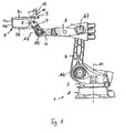
- Fig. 1 shows a conventional industrial robot 1 with a base 2, a about the first axis of the robot 1, the vertical axis A1 rotatable carousel, one at this about the second axis, the horizontal axis A2, pivotable rocker arm 4, a this at the third axis, the horizontal axis A3 pivotally articulated robot arm 5.
- the robot arm 5, the robot hand 6 is fixed, which consists of three axes A4 to A6 consists of pivotable elements.
- an X-welding gun 8 is fixed, the two electrode arms 8a, 8b to X each other under the drive of a main gun motor 9 having a spindle drive 10 pivotally and the pin electrodes 11a, 11b are thus pressed against 29rai touchde parts.
- the main gun motor 9 is connected to the electrode arm 8b, the free spindle end of the spindle 12 to the electrode arm 8a.
- the welding gun 8 is shown enlarged in FIG. Furthermore, 2 positions P1, P2, P3, P4 are indicated for the arrangement of pressure sensors in FIG.
- the positions P1 are in the area of the electrodes 11a, 11b and directly measure the pressure exerted on them.
- the positions P2 are located on the electrode arms and measure bends thereof due to the pressed electrodes 11a, 11b.
- the position P3 is located at a connecting lever 9a to the attachment point of the electric motor 9 and can accordingly measure its bending when pressure is applied to the electrodes 11a, 11b.
- At P4 is a piezoelectric sensor for measuring the pressure force. This sensor is preferably integrated in the main gun motor.
- Type and location of the force measurement are not essential.
- the choice of the sensor and its location are influenced by the mechanical characteristics of the clamp and the suitability of the sensor. Further developments can therefore decisively influence the choice of the sensor as well as its installation location.
- the pressure sensors are preferably in the form of strain gauges 13 with strain gauges 14, the latter being arranged in the form of a bridge circuit, as shown in FIG.
- the signal measured by said pressure data sensors flows as an actual signal into the force-position control of the electric motor 9 according to the invention.
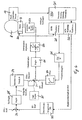
- FIG. 4 A block diagram of an inventive device for force-position control of the engine is shown in FIG. 4.
- the pliers 8 shown schematically are driven by the motor 9 and has at least one force-moment sensor 13 in the manner described above.
- the control of the electric motor 9, which is an electric servo motor, has, in a manner known per se, a speed controller 21, a torque limiter 22 and an inverter 23.
- the motor is provided with a resolver 24 which is connected to a resolver-to-digital converter RDW-25, via which the position detection or the detection of the position of the motor 9 takes place.
- a differentiator 26 and a filter 27 the actual rotational speed of the motor 9 is thus detected, which is fed to a comparator 30 upstream of the rotational speed regulator 21.
- the force-torque sensor 13 is connected to a force sensor card 31, in which a potential separation and filtering as well as the supply of the sensor takes place.
- a force sensor card 31 Connected to the force sensor card 31 is an AD converter 32, with which the measured force-actual value is digitized. If necessary, this is supplied to a conversion unit 33, in which the digitized force-actual value measured, for example, at the positions P2, P3 or P4 is converted into the actual force of the force between the electrodes.
- the conversion factor may be determined from a calibration of the force measured at position P2, P3 or P4 based on the force detected between the electrodes at position P1 in a calibration process.
- the converted force enters as an actual force in a comparator 34, which is supplied as desired value, the desired value.
- a force regulator 35 On the basis of the comparison, a force regulator 35 generates a manipulated variable with regard to the force to be applied, which is converted into a feed for the electric motor 3 in another converter 34 and which is supplied as target speed to the comparator 30, which is due to a comparison between the o.g. Actual speed of the output of the filter 27 and the target speed of the converter 34 generates a control signal for the speed controller 21. In the normal position control mode, the signal of a position controller 35 supplied to the comparator 30 will enter this.
- step A To control the force applied to the workpiece by the forceps 8, an actual force is detected via the force-moment sensor 13 in a step A (FIG. 5), which processes, outputs, filters and digitizes the signal emitted by the sensor (step B).
- the said force signal which is given as an increment, is then converted by means of a fixed conversion factor in the conversion unit 33 into the force of the forceps in Newton as the actual force (step C).
- step D There is a comparison with the by the Control (step D ') predetermined target force and the confirmation of the control deviation.
- step D the output of a manipulated variable
- step E the output of a manipulated variable
- step E the output of a manipulated variable
- This target speed is the self-existing control (speed controller 21, torque limiter 22 and inverter 23) for the motor 9 is supplied (step F), whereby the movement of the motor in the respective position and thus controlled (step E) and thus a Force change in the forceps 8 in accordance with the given between motor and force-moment sensor of the forceps 8 spring constant and changes in position to exercise the desired (desired) force is effected.
- the resulting force is in turn detected and optionally fed to a new control process (step H).
- FIG. 6a shows a diagram during the traverse of a force staircase applied to a welding tongs with identical power stages.
- the signal measured by means of an external dynamometer between the caps of a welding gun is denoted by I.
- the diagrams show the signal recorded with an oscilloscope.
- the apparent signal noise is due to EMC interference on the test lead.
- Scales are approximately 500 Newton / division in the Y direction and 2 seconds division in the X direction.
- the desired value is indicated by S in FIG. 6a. It shows when driving down this power staircase follows in force-position control according to the invention actual and setpoint match.
- Fig. 6b shows a corresponding force measurement when driving off a power staircase in torque operation. The setpoint is not entered here. It turns out that with a mere specification of the motor current, the resulting electrode forces scatter strongly and current changes only follow inadequately.
- FIG. 7 shows the relationship between the position of the electric motor measured via the integrated resolver 24, the motor position being indicated by increments INC, and the resulting electrode force between the electrodes (curve P) measured by a force sensor at position P1 of FIG 2 as part of a calibration process or the corresponding values of the integrated force sensor at the position P4 of FIG. 2 for several points when the pliers are stopped: curve Q in FIG. 7.
- the force and position values can be stored during the changeover of the position and force control and the changes of the positions compared with each other. If the corresponding values no longer match one another, then it can be concluded that either the calibration is incorrect, the sensor is defective, the signal chain has been interrupted or the sensor has been incorrectly initialized. This is of particular importance when using piezoelectric sensors whose evaluation unit must receive a reset signal at zero force in order to prevent the measured value from drifting away.
- the evaluation of the course of electrode force and motor position during the actual welding process also provides information about the quality of the welding spot produced.
- the pliers must follow as a result of the melting of the material to be welded, ie they must adjust their position of the compressed weld nugget while maintaining the electrode force. This is done on the one hand by the elasticity of the pliers mechanism, on the other hand also by the regulation of the electrode force.
Description
Die Erfindung betrifft ein Verfahren und eine Vorrichtung zum Steuern der Andruckkraft der Elektroden einer durch einen Elektromotor angetriebenen Schweißzange, insbesondere eines Industrieroboters, während eines Schweißvorganges.The invention relates to a method and a device for controlling the pressing force of the electrodes of a welding tongs driven by an electric motor, in particular of an industrial robot, during a welding operation.
Schweißzangen zum Punktschweißen wurden früher ausschließlich von pneumatischen oder hydraulischen Aktoren angetrieben. Nachteilig ist die notwendige Bereitstellung des Kraftmediums, in der Regel Öl, und die damit verbundene Verschmutzung durch dieses. Weder ein kontrolliertes Schließen und Öffnen noch ein sanftes Aufsetzen der Elektroden auf die zu verschweißenden Bleche waren möglich. Der Kraftverlauf war nicht kontrollierbar. Zur Behebung dieser Probleme werden in verstärktem Maße elektrische Antriebe eingesetzt. Ein entsprechender Servoantrieb besteht in der Regel aus einem bürstenlosen Gleichstrommotor mit nachgeordnetem hoch untersetzendem Getriebe, welches in der Regel einen Linearabtrieb mit einer Kugelrollenspindel aufweist. Derartige Antriebe können zur Aus- bzw. Umrüstung bestehender Zangenmechaniken verwendet werden. Der Zangen-Servoantrieb kann als Zusatzachse zum Motor betrieben und in die Robotersteuerung integriert werden, was konsistentes Bedienen und Programmieren, synchrones Schließen und Öffnen der Zange sowie kontrollierten Kraftaufbau und Kraftsteuerung ermöglicht. Die Ansteuerung des Zangenantriebs erfolgt während des Schließens und Öffnens lagegeregelt. Im geschlossenen zustand, d.h. wenn die Elektroden Blechberührung haben, erfolgt der Aufbau der Schweißkraft und deren Steuerung oder Regelung bis zum Ende des Schweißvorganges.Previously, spot welding welding guns were exclusively driven by pneumatic or hydraulic actuators. A disadvantage is the necessary provision of the force medium, usually oil, and the associated pollution by this. Neither a controlled closing and opening nor a gentle placing of the electrodes on the sheets to be welded were possible. The force curve was not controllable. To overcome these problems, electric drives are increasingly being used. A corresponding servo drive usually consists of a brushless DC motor with downstream high-stepping gear, which usually has a linear output with a ball screw. Such drives can be used to remove or retrofit existing Pliers mechanisms are used. The pliers servo drive can be operated as an additional axis to the motor and integrated into the robot control, which allows consistent operation and programming, synchronous closing and opening of the pliers and controlled force and force control. The control of the pliers drive is controlled position during closing and opening. In the closed state, that is, when the electrodes have sheet metal contact, the build up of the welding force and its control or regulation takes place until the end of the welding process.
Die Aufbringung der Schweißkraft erfolgt in der Regel im Momentenbetrieb, bei der zur Aufbringung einer gewünschten Elektrodenkraft ein dieser entsprechender Motorstrom vorgegeben wird, um damit ein definiertes Motormoment zu erreichen. Dies kann dadurch realisiert werden, dass ein virtueller Punkt im Blech angefahren wird. Da sich die Elektroden nach Berührung der Blechoberfläche nur minimal bewegen, geht die vom Drehzahlregeler der Motorsteuerung ausgegebene Stellgröße (Motormoment bzw. Motorstrom) aufgrund des PI-Verhaltens des Reglers in die Begrenzung. Wird die Begrenzung auf dem zielwert entsprechender Elektroden in Kraft gesetzt, soll sich im geschlossenen Zustand der Zange automatisch die gewünschte Elektrodenkraft einstellen. Die so erzeugte Elektrodenkraft entspricht aufgrund von Lagerreibungen, Stick-Slip-Effekten, Reibung, Selbsthemmung und Losbrechkräften im Getriebe nur bedingt dem erzeugten Motorstrom. Des weiteren haben Materialerwärmungen und Alterungseffekte einen negativen Einfluss. Im Betrieb zeigt sich bei höheren Kräften eine Verklemmung der Mechanik. Dies führt bei hartem Aufsetzen der Elektroden auf das Blech und der hohen resultierenden Verzögerungskräfte zu einer momentan erhöhten Elektrodenkraft, die in Folge der eintretenden Verklemmung der Mechanik bestehen bleibt. Die so entstehenden Kraftfehler können nur durch aufwendige und häufige Kalibriermaßnahmen teilweise vermindert werden. Ein weiteres Problem besteht darin, dass die Zangenmechanik im verklemmten Zustand auf kleine Änderungen des Motormoments nicht reagiert und erst bei erheblichen Änderungen die Losbrechkräfte erreicht und sich entsprechend ruckartig bewegt. Dies alles zeigt sich beim Abfahren einer Krafttreppe im Momentenbetrieb darin, dass die Elektrodenkräfte stark streuen und Stromänderungen nur unzureichend folgen. Da die damit erreichte Genauigkeit der Elektrodenkraft aufgrund der hohen Reibanteile des mechanischen Systems oft nicht ausreicht, sind aus der Praxis Hardware-Lösungen bekannt, die mit Hilfe eines Kraftsensors einen Regelkreis mit dem Motorstrom als Stellgröße aufbauen. Dies erfordert spezielle Frequenzumrichter, die nicht in eine existierende Robotersteuerung integrierbar sind. Insbesondere das Umschalten zwischen Lage-Drehzahlregelung (während Öffnen und Schließen der Zange) und Kraft-Motorstrom-Regelung (beim Aufbringen der Schweißkraft) macht erhebliche Probleme, da diese nicht zeitlich mit der Bahn des Roboters synchronisierbar sind und insbesondere nicht während einer Bewegung ausgeführt werden können.The application of the welding force is usually carried out in torque operation, in which a corresponding motor current is predetermined for applying a desired electrode force in order to achieve a defined engine torque. This can be realized by approaching a virtual point in the sheet metal. Since the electrodes move only minimally after touching the sheet metal surface, the manipulated variable (motor torque or motor current) output by the speed controller of the motor control system is limited due to the PI behavior of the controller. If the limitation on the target value of corresponding electrodes is put into effect, the desired electrode force should automatically set in the closed state of the forceps. The electrode force thus generated corresponds due to bearing friction, stick-slip effects, friction, self-locking and breakaway forces in the transmission only limited to the generated motor current. Furthermore, material warming and aging effects have a negative impact. In operation, a jamming of the mechanics appears at higher forces. This results in hard placement of the electrodes on the sheet and the high resulting retarding forces to a momentarily increased electrode force, which persists as a result of the incoming jamming of the mechanism. The resulting force errors can only by consuming and frequent calibration measures are partially reduced. Another problem is that the clamp mechanism does not react in the jammed state to small changes in engine torque and reaches the breakaway forces only with significant changes and moves accordingly jerky. All this is shown when driving off a power staircase during torque operation in that the electrode forces scatter strongly and current changes only insufficiently. Since the accuracy of the electrode force achieved with this is often insufficient due to the high friction components of the mechanical system, hardware solutions are known in practice which use a force sensor to build up a control loop with the motor current as a manipulated variable. This requires special frequency converters that can not be integrated into an existing robot controller. In particular, switching between position-speed control (during opening and closing of the clamp) and force-motor current control (when applying the welding force) poses considerable problems, since they can not be synchronized in time with the path of the robot and, in particular, are not executed during a movement can.
Die JP 10 094882 A betrifft ein Verfahren und eine Vorrichtung zum Detektieren und Steuern des Drucks einer Schweißzange, indem der elastische Versatz der Elektrodenspitzen nach der Druckaufbringung mittels der Schweißzange gemessen wird und der Druck aufgrund der Bewegung erhalten wird. Hierzu wird eine Elektrodenspitze der Schweißzange mittels eines Servomotors gegen die andere Schweißzange bewegt. Wenn die eine Elektrodenspitze auf der anderen Elektrodenspitze anschlägt und (wohl genauer auf das zwischen beide liegende Teil) und weiter zum Andrücken gegen die andere Elektrodenspitze angetrieben wird, wird ein Druck und eine elastische Deformation in der Elektrodenspitze 10 erzeugt. Wenn die Elektroden sich berühren steigt der Strom durch den Motor stark an. Die Drehung eines Encoders soll von der Zeit des Wechsels des Laststromes gemessen werden und die elastische Deformation der Elektrodenspitze wird hieraus berechnet. Im Folgenden soll dann der Druck F aus der berechneten elastischen Deformation und dem Druck F berechnet werden. Diese Aussage ist völlig unverständlich. Im Weiteren ist gesagt, dass ein Druckkorrektursystem den Servomotor durch einen Motortreiber in Vorwärts- und Rückwärtsrichtung antreibt, um den Druck auf einen geeigneten Wert zu setzen. So soll der Druck korrekt gemessen werden können, ohne durch Störungen beeinträchtigt zu sein, wobei offen ist, wie die Druckkraft und Zangenkraft bestimmt werden.JP 10 094882 A relates to a method and an apparatus for detecting and controlling the pressure of a welding gun by measuring the elastic displacement of the electrode tips after the pressure application by means of the welding gun and the pressure due to the movement is obtained. For this purpose, an electrode tip of the welding gun is moved by means of a servo motor against the other welding gun. When the one electrode tip abuts on the other electrode tip and is driven (more precisely to the part lying between both) and further for pressing against the other electrode tip, a pressure and an elastic deformation is generated in the
Die JP 5-261558 A beschreibt nicht mehr als das Prinzip der Steuerung einer servomotorischen Schweißzange, bei der mittels eines Motors eine Spindel bewegt wird, um mittels Drucksteuerung eine Kraft zwischen Zangenelektroden zu erzeugen. Es soll eine Drucksteuerung in Echtzeit und mit hoher Präzision erfolgen, indem die Zahl der Umdrehungen des Antriebsmotors und der Öffnungszustand der Zange frei gelehrt werden. Eine Messung des erzeugten Druckes ist nicht vorgesehen.JP 5-261558 A describes nothing more than the principle of controlling a servo-motor welding gun in which a spindle is moved by means of a motor in order to generate a force between pliers electrodes by means of pressure control. It is a pressure control in real time and with high precision by the number of revolutions of the drive motor and the opening state of the pliers are taught free. A measurement of the pressure generated is not provided.
Die US 5,981,898 A beschreibt ein Verfahren zum Steuern des Elektrodendrucks einer Schweißzange, wobei eine durchschnittliche Motorposition für ein bestimmtes Motormoment unter Mittelung mehrerer Messungen bei einem zuvor fest eingestellten Motorstrom der Zuordnung zur Zangenkraft offen bleibt. Die hier ermittelte durchschnittliche Position für ein bestimmtes Motormoment soll als Zielposition des Motors während des Schweißvorgangs genutzt werden.US 5,981,898 A describes a method for controlling the electrode pressure of a welding gun, wherein an average engine position for a given engine torque remains open by averaging a plurality of measurements at a previously fixed motor current of the assignment to the force of forceps. The average position determined here for a specific engine torque should be used as the target position of the engine during the welding process.
Die EP 1 088 614 betrifft eine Roboterschweißzange als solche und befasst sich lediglich mit der mechanischen Ausgestaltung des Spindelantriebs.EP 1 088 614 relates to a robot welding gun as such and deals only with the mechanical design of the spindle drive.
Die US 2003/0132201 A1 betrifft ein Verfahren und eine Vorrichtung zum gesteuerten Widerstandspunktschweißen und insbesondere eine Steuervorrichtung zum Punktschweißen, die den Motor- und Schweißstrom einstellt. Hier wird ein fester Motorstrom für eine bestimmte gewünschte Schweißkraft an dem Motor vorgegeben (Momentenbetrieb).US 2003/0132201 A1 relates to a method and a device for controlled resistance spot welding, and more particularly to a spot welding control device which adjusts the motor and welding current. Here, a fixed motor current for a specific desired welding force on the motor is specified (torque operation).
Der Erfindung liegt die Aufgabe zugrunde unter Vermeidung der oben genannten Nachteile ein Verfahren und eine Vorrichtung zum Steuern der Andruckkraft einer Schweißzange zu schaffen, mittels denen die gewünschte Andruckkraft mit hoher Genauigkeit erreicht werden kann.The invention has for its object to avoid the above-mentioned disadvantages to provide a method and apparatus for controlling the pressing force of a welding gun, by means of which the desired pressing force can be achieved with high accuracy.
Erfindungsgemäß wird die genannte Aufgabe bei einem Verfahren der eingangs genanten Art durch die Merkmale des Anspruchs 1 gelöst, welches dadurch gekennzeichnet ist, dass die Andruckkraft durch Steuern der Motorposition geregelt wird.According to the invention, the object is achieved in a method of the type mentioned by the features of claim 1, which is characterized in that the pressing force is controlled by controlling the motor position.
Zur Lösung der genannten Aufgabe sieht die Erfindung weiterhin eine Vorrichtung der gattungsgemäßen Art durch die Merkmale des Anspruchs 11 vor.To achieve the above object, the invention further provides a device of the generic type by the features of claim 11.
Erfindungsgemäß wird im Gegensatz zum Stand der Technik die Zangenkraft nicht durch Steuerung oder auch Regelung des Motorstroms, sondern über die Motorposition unter Berücksichtigung der Federkonstante der Zangenmechanik gesteuert bzw. geregelt. Die Beziehung zwischen Motorposition, die in an sich bekannter Weise über einen integrierten Resolver oder Inkrementalgeber gemessen wird und der resultierten Elektrodenkraft hat sich als annähernd linear erwiesen und entspricht näherungsweise der Federkonstante der Schweißzange. Auch das Verhältnis der an der Zange mittels eines integrierten Kraft-Sensors erfassten Kräfte zu den tatsächlich an den Elektrodenkappen ausgeübten Kräfte, die im Rahmen eines Kalibriervorgangs gemessen werden können, erweist sich als hoch linear. Die Erfindung beinhaltet also eine Regelung und eine Regelvorrichtung für die Zangenkraft mit einem Regelkreis, wobei Regelgröße die Zangenkraft und Stellgröße die Motorposition, nicht aber wie beim Stande der Technik, der Motorstrom ist.According to the invention, the forceps force is controlled or regulated not by controlling or regulating the motor current, but on the motor position, taking into account the spring constant of the pliers mechanism in contrast to the prior art. The relationship between motor position, which is measured in a conventional manner via an integrated resolver or incremental encoder and the resulting electrode force has proven to be approximately linear and corresponds approximately to the spring constant of the welding gun. Also, the ratio of the forceps by means of a integrated forces sensor to the actually applied to the electrode caps forces that can be measured during a calibration process, proves to be highly linear. The invention thus includes a control and a control device for the forceps force with a control loop, wherein controlled variable, the forceps and manipulated variable, the motor position, but not as in the prior art, the motor current.
In einer bevorzugten Ausgestaltung des erfindungsgemäßen Verfahrens ist vorgesehen, dass die Motorposition mittels mindestens eines in den Elektromotor integrierten Resolvers oder Inkrementalgeber gemessen wird. Hierzu ist die erfindungsgemäße Vorrichtung gekennzeichnet durch durch einen in den Motor integrierten Resolver zur Messung der Motorposition. Während die Andruckkraft grundsätzlich direkt an den Elektroden gemessen werden kann, wobei allerdings die EMV Probleme verursachen kann, sieht die Erfindung in bevorzugter Weise vor, dass die Andruckkraft mittels Sensoren an einem von den Elektroden entfernten Ort der Schweißzange erfasst wird. In bevorzugter Ausgestaltung ist dabei vorgesehen, dass aus Stellgröße eines Kraftgebers und der Berücksichtigung der Federkonstante der Schweißzange eine Weggröße (Weg, Weginkrement) bestimmt wird, wobei weiterhin die bestimmte Weggröße mittels einer Drehzahlregelung weiterverarbeitet wird.In a preferred embodiment of the method according to the invention it is provided that the motor position is measured by means of at least one integrated in the electric motor resolver or incremental encoder. For this purpose, the device according to the invention is characterized by a built-in motor resolver for measuring the position of the motor. While the pressure force can in principle be measured directly at the electrodes, although the EMC can cause problems, the invention provides in a preferred manner that the pressure force is detected by means of sensors at a location remote from the electrodes welding tongs. In a preferred embodiment, it is provided that from the manipulated variable of a force transmitter and the consideration of the spring constant of the welding gun a distance (path, Weginkrement) is determined, and further the particular distance is further processed by means of a speed control.
Während eine weitere bevorzugte Ausgestaltung des erfindungsgemäßen Verfahren vorsieht, dass die Andruckkraft mittels Dehnungsmessstreifen an der Schweißzange erfasst wird, zeichnet sich eine äußerst bevorzugte Ausgestaltung dadurch aus, dass die Andruckkraft mittels Sensoren an einem von den Elektroden entfernten Ort der Schweißzange erfasst wird.While a further preferred embodiment of the method according to the invention provides that the pressure force is detected by means of strain gauges on the welding tongs, an extremely preferred embodiment is characterized in that the pressure force is detected by means of sensors at a location of the welding tongs remote from the electrodes.
Zur Erfassung der an der Schweißzange ausgeübten Kraft ist in Weiterbildung vorgesehen, dass die Andruckkraft mittels Sensoren an einem von den Elektroden entfernten Ort der Schweißzange erfasst wird, wobei insbesondere die Andruckkraft mittels Dehnungsmessstreifen an der Schweißzange erfasst wird und/oder die Schweißkraft in Brückenschaltung von Dehnungsmessstreifen an der Schweißzange erfasst wird.In order to detect the force exerted on the welding gun, it is provided in a development that the pressing force is detected by means of sensors at a location of the welding gun remote from the electrodes, wherein in particular the pressing force is detected by means of strain gauges on the welding gun and / or the welding force in bridge connection of strain gauges is detected at the welding gun.
Demgemäß ist in Weiterbildung die erfindungsgemäße Vorrichtung dadurch ausgestaltet, dass die Messeinrichtungen durch Dehnungsmessstreifen gebildet sind, wobei Dehnungsmessstreifen an Zangenarmen angeordnet sind oder aber mindestens ein Dehnungsmessstreifen an einem Verbindungshebel von Motor zum mit ihm festverbundenen Schweißzangenarm angeordnet ist.Accordingly, in development, the device according to the invention is configured in that the measuring devices are formed by strain gauges, wherein strain gauges are arranged on forceps arms or at least one strain gauge is arranged on a connecting lever of the motor fixed to him welding gun arm.
Eine weitere bevorzugte Ausgestaltung der erfindungsgemäßen Vorrichtung sieht vor, dass Dehnungsmessstreifen als Messbrücke geschaltet sind. Darüber hinaus kann in erfindungsgemäßer Weiterbildung eine Einrichtung zur Bearbeitung und Isolierung des durch den Kraft-Sensor gemessenen Kraft-Signals vorgesehen sein.A further preferred embodiment of the device according to the invention provides that strain gauges are connected as a measuring bridge. In addition, according to the invention, a device for processing and isolating the force signal measured by the force sensor can be provided.
Weitere bevorzugte Ausgestaltung der erfindungsgemäßen Vorrichtung sind einen Wandler zur Wandlung des gemessenen Kraftsignals in einen digitalisierten Kraft-Ist-Wert gekennzeichnet, wobei insbesondere eine Umrechnungseinheit zur Umrechnung des gemessen, ggf. digitalisierten Kraft-Ist-Wert-Signals in eine physikalische Zangenkraft und/oder eine Vergleichseinrichtung (34, 35) zum Vergleich von gemessener physikalischer Ist-Kraft und gewünschter Soll-Kraft zur Bestimmung einer Regelabweichung und einer Stellgrößen vorgesehen sind.Further preferred embodiment of the device according to the invention are a converter for converting the measured force signal into a digitized force-actual value, in particular a conversion unit for converting the measured, possibly digitized force-actual-value signal into a physical force and / or force a comparison device (34, 35) is provided for comparing measured actual physical force and desired setpoint force for determining a system deviation and an actuating variable.
Andere Ausgestaltungen der erfindungsgemäßen Vorrichtung zeichnen sich durch eine Umrechnungseinheit zur Umrechung der Kraft-Stellgröße in einem Verfahrweg (ΔF ~ Δs) des Elektromotors aus, wobei insbesondere weiterhin eine Vergleichseinrichtung zum Vergleich der Soll-Position mit einer am Motor erfassten Ist-Position und insbesondere ein Positionsregler zur Regelung der Position des Elektromotors vorgesehen sind. Erfindungsgemäß arbeitet der Kraftregler nach dem Lageregler. Auch wäre der Einsatz des Kraftreglers vor dem Lageregler möglich.Other embodiments of the device according to the invention are characterized by a conversion unit for converting the force control variable in a travel (.DELTA.F ~ .DELTA.s) of the electric motor, wherein in particular further comprises a comparison device for comparing the desired position with an actual position detected on the engine and in particular a Position controller are provided for controlling the position of the electric motor. According to the invention, the force regulator works according to the position controller. It would also be possible to use the force controller in front of the position controller.
In weiterer bevorzugter Ausgestaltung des erfindungsgemäßen Verfahrens ist vorgesehen, dass eine Kalibrierung der Verhältnisse von zangenkraft zu Weg und/oder von Sensorwert zu Zangenkraft erfolgt, die der Federkonstante entspricht.In a further preferred embodiment of the method according to the invention, it is provided that a calibration of the ratios of forceps force to travel and / or from sensor value to forceps force takes place, which corresponds to the spring constant.
Weitere Vorteile und Merkmale der Erfindung ergeben sich aus den Ansprüchen und aus der nachfolgenden Beschreibung, in der ein Ausführungsbeispiel der Erfindung unter Bezugnahme auf die Zeichnungen im einzelnen erläutert ist. Dabei zeigt:
- Fig. 1
- einen mit einer X-Schweißzange an seiner Hand versehenen Sechs-Achs-Industrieroboter;
- Fig. 2
- die Schweißzange der Fig. 1 in vergrößerter Darstellung mit Positionen zur Anordnung von Drucksensoren;
- Fig. 3
- die Anordnung von Dehnungsmessstreifen zu einer Messbrücke als Sensor;
- Fig. 4
- ein Blockschaltbild zur Kraft-Lage-Regelung gemäß der Erfindung;
- Fig. 5
- ein Ablaufdiagramm zur erfindungsgemäßen Kraft-Lage-Regelung;
- Fig. 6a, b
- Diagramme des Abfahrens einer Krafttreppe bei Kraft-Lage-Regelung (Fig. 7a) und in herkömmlichem Momentenbetrieb (Fig. 7b); und
- Fig. 7
- ein Diagramm zur Kraft-Sensor-Kalibrierung.
- Fig. 1
- a six-axis industrial robot equipped with X-welding gun on his hand;
- Fig. 2
- the welding gun of Figure 1 in an enlarged view with positions for the arrangement of pressure sensors.
- Fig. 3
- the arrangement of strain gauges to a measuring bridge as a sensor;
- Fig. 4
- a block diagram of the force-position control according to the invention;
- Fig. 5
- a flow chart for force-position control according to the invention;
- Fig. 6a, b
- Diagrams of the departure of a force staircase in force-position control (FIG. 7a) and in conventional torque operation (FIG. 7b); and
- Fig. 7
- a diagram for force sensor calibration.
Die Erfindung betrifft die Regelung der Andruckkraft einer mittels eines Elektromotors angetriebenen Schweißzange durch Regelung der Motorposition des Elektromotors.The invention relates to the regulation of the pressing force of a welding tongs driven by an electric motor by controlling the motor position of the electric motor.
Die Fig. 1 zeigt einen herkömmlichen Industrieroboter 1 mit einem Sockel 2, einem um die erste Achse des Roboters 1, die vertikale A1-Achse drehbaren Karussell, einem an diesem um die zweite Achse, die horizontale A2-Achse, verschwenkbaren Roboterschwinge 4, einem an diesem um die dritte Achse, die horizontale A3-Achse schwenkbar angelenkten Roboterarm 5. Am Roboterarm 5 ist die Roboterhand 6 befestigt, die aus um drei Achsen A4 bis A6 verschwenkbaren Elementen besteht. Am Handflansch 7 der Roboterhand 6 ist eine X-Schweißzange 8 befestigt, deren beide Elektrodenarme 8a, 8b um X zueinander unter dem Antrieb eines einen Zangenhauptmotor 9 aufweisenden Spindelantriebs 10 verschwenkbar und deren Stiftelektroden 11a, 11b damit gegen zu verscheißende Teile anpressbar sind. Der Zangenhauptmotor 9 ist mit dem Elektrodenarm 8b verbunden, das freie Spindelende der Spindel 12 mit dem Elektrodenarm 8a.Fig. 1 shows a conventional industrial robot 1 with a base 2, a about the first axis of the robot 1, the vertical axis A1 rotatable carousel, one at this about the second axis, the horizontal axis A2,
Die Schweißzange 8 ist in der Fig. 2 vergrößert dargestellt. Weiterhin sind in der Fig. 2 Positionen P1, P2, P3, P4 zur Anordnung von Drucksensoren angegeben.The
Die Positionen P1 befinden sich im Bereich der Elektroden 11a, 11b und messen direkt den auf diese ausgeübten Druck. Die Positionen P2 befinden sich an den Elektrodenarmen und messen Biegungen derselben aufgrund der gegeneinander gedrückten Elektroden 11a, 11b. Die Position P3 befindet sich an einem Verbindungshebel 9a zum Befestigungspunkt des Elektromotors 9 und kann demgemäss dessen Biegung bei Druckausübung auf die Elektroden 11a, 11b messen. Bei P4 befindet sich ein piezo-elektrischer Sensor zur Messung der Andruckkraft. Dieser Sensor ist vorzugsweise im Zangenhauptmotor integriert.The positions P1 are in the area of the electrodes 11a, 11b and directly measure the pressure exerted on them. The positions P2 are located on the electrode arms and measure bends thereof due to the pressed electrodes 11a, 11b. The position P3 is located at a connecting lever 9a to the attachment point of the
Art und Ort der Kraftmessung sind nicht wesentlich. Die Wahl des Sensors und dessen Einbauort werden beeinflusst durch die mechanischen Gegebenheiten der Zange und der Eignung des Sensors. Weiterentwicklungen können daher die Wahl des Sensors wie dessen Einbauort entscheidend beeinflussen.Type and location of the force measurement are not essential. The choice of the sensor and its location are influenced by the mechanical characteristics of the clamp and the suitability of the sensor. Further developments can therefore decisively influence the choice of the sensor as well as its installation location.
Woher der gemessene Kraftwert kommt, ist für die Regelung nicht wesentlich und wird nur beispielhaft exemplarisch dargestellt.Where the measured force value comes from is not essential for the regulation and is shown as an example only.
Die Drucksensoren sind vorzugsweise in Form von DMS-Messbrücken 13 mit Dehnungsmessstreifen 14 ausgebildet, wobei letztere in Form einer Brückenschaltung angeordnet sind, wie dies in der Fig. 3 dargestellt ist.The pressure sensors are preferably in the form of
Das von den genannten Druckdatensensoren gemessene Signal fließt als Ist-Signal in die erfindungsgemäße Kraft-Lage-Regelung des Elektromotors 9 ein.The signal measured by said pressure data sensors flows as an actual signal into the force-position control of the
Ein Blockschaltbild einer erfindungsgemäßen Vorrichtung zur Kraft-Lage-Regelung des Motors ist in der Fig. 4 dargestellt.A block diagram of an inventive device for force-position control of the engine is shown in FIG. 4.
Die schematisch dargestellte Zange 8 ist durch den Motor 9 angetrieben und weist mindestens einen Kraft-Momenten-Sensor 13 in der vorstehend beschriebenen Weise auf.The
Die Steuerung des Elektromotors 9, der ein elektrischer Servomotor ist, weist in an sich bekannter Weise einen Drehzahlregler 21, einen Drehmomentbegrenzer 22 sowie einen Umrichter 23 auf.The control of the
Der Motor ist mit einem Resolver 24 versehen, der mit einem Resolver-Digitalwandler-RDW-25 verbunden ist, worüber die Positionserfassung oder die Erfassung der Stellung des Motors 9 erfolgt. Über einen Differenzierer 26 sowie einen Filter 27 wird derart die Ist-Drehzahl des Motors 9 erfasst, die einem dem Drehzahlregler 21 vorgeordneten Vergleicher 30 zugeführt wird.The motor is provided with a
Der Kraft-Momenten-Sensor 13 ist mit einer Kraftsensor-Karte 31 verbunden, in dem eine Potentialtrennung und Filterung sowie die Versorgung des Sensors erfolgt. An die Kraft-Sensorkarte 31 schließt sich ein AD-Wandler 32 an, mit dem der gemessene Kraft-Ist-Wert digitalisiert wird. Dieser wird ggf. einer Umrechnungseinheit 33 zugeführt, in der der beispielsweise an den Positionen P2, P3 oder P4 gemessene digitalisierte Kraft-Ist-Wert in die tatsächliche Zangenkraft zwischen den Elektroden umgerechnet wird. Der Umrechnungsfaktor kann aufgrund einer Kalibrierung der an der Position P2, P3 oder P4 gemessenen Kraft aufgrund der zwischen den Elektroden an der Position P1 in einem Kalibrierungsvorgang ermittelten Kraft bestimmt werden. Die umgerechnete Kraft geht als Ist-Kraft in einen Vergleicher 34 ein, dem als Sollwert die gewünschte Soll-Kraft zugeführt wird. Aufgrund des Vergleichs erzeugt ein Kraftregler 35 eine Stellgröße hinsichtlich der aufzubringenden Kraft, die in einem weiteren Umrechner 34 in einen Vorschub für den Elektromotor 3 umgerechnet wird und die als Soll-Drehzahl dem Vergleicher 30 zugeführt wird, der aufgrund eines Vergleichs zwischen der o.g. Ist-Drehzahl des Ausgangs des Filters 27 und der Soll-Drehzahl des Umrechners 34 ein Stellsignal für den Drehzahlregler 21 erzeugt. In dieses wird im normalen Lageregelbetrieb das Signal eines dem Vergleicher 30 zugeführten Lagereglers 35 eingehen.The force-
Zur Regelung der auf das Werkstück durch die Zange 8 aufgebrachten Kraft wird eine tatsächliche Kraft über den Kraft-Momenten-Sensor 13 in einem Schritt A (Fig. 5) erfasst, das vom Sensor abgegebene Signal aufbereitet, gefiltert und digitalisiert (Schritt B). Das genannte Kraftsignal, das als Inkrement gegeben ist wird mittels eines festen Umrechnungsfaktors anschließend in der Umrichtungseinheit 33 in die Zangenkraft in Newton als Ist-Kraft umgerechnet (Schritt C) . Es erfolgt ein Vergleich mit der durch die Steuerung (Schritt D') vorgegebenen Soll-Kraft und die Bestätigung der Regelabweichung. Anschließend erfolgt durch Multiplikation mittels eines Faktors, wie eines P-Faktors bei beispielsweise einem P-Regler die Ausgabe einer Stellgröße (Schritt D), die wiederum im genannten Umrechner 34 in Positionsvorschübe und in eine Soll-Drehzahl entsprechend dem Quotienten aus Positionsdelta und Systemtakt umgerechnet wird (Schritt E). Diese Soll-Drehzahl wird der an sich vorhandenen Steuerung (Drehzahlregler 21, DrehmomentBegrenzer 22 und Umrichter 23) für den Motor 9 zugeführt (Schritt F), wodurch die Bewegung des Motors in die jeweilige Position und damit gesteuert wird (Schritt E) und damit eine Kraftänderung in der Zange 8 entsprechend der zwischen Motor und Kraft-Momenten-Sensor der Zange 8 gegebenen Federkonstante sowie vorgenommenen Lageänderung zur Ausübung der gewünschten (Soll-)kraft bewirkt wird. Die sich ergebende Kraft wird wiederum erfasst und ggf. einem erneuten Regelvorgang zugeführt (Schritt H).To control the force applied to the workpiece by the
Die Signalverarbeitung erfolgt bei der zeitdiskreten digitalen Regelung der Motorposition über Drehzahlwerte entsprechend Solldrehzahl = Δs/IPO-Takt (Δs= Weginkrement; der IPO-Takt ist der Systemtakt des verwendeten Rechners) entsprechend der Federkonstante der Zangenmechanik. Der Kraftregler liefert, wie ein herkömmlicher Lageregler, eine Stellgröße in Form einer Drehzahl liefert, eine Stellgröße in Form eines Weges bzw. Position. Pro Systemtakt einmal ausgeführt/berechnet ist dieses Δs/Δt=v, die Solldrehzahl für den digitalen Drehzahlregler.The signal processing takes place in the discrete-time digital control of the motor position via speed values corresponding to setpoint speed = Δs / IPO cycle (Δs = path increment, the IPO cycle is the system clock of the computer used) corresponding to the spring constant of the clamp mechanism. The force controller supplies, like a conventional position controller, a manipulated variable in the form of a speed, a manipulated variable in the form of a path or position. Once executed / calculated per system clock, this Δs / Δt = v, the setpoint speed for the digital speed controller.
Die Fig. 6a zeigt ein Diagramm beim Abfahren einer auf eine Schweißzange aufgebrachten Krafttreppe mit identischen Kraftstufen. Das mittels eines externen Kraftmessers zwischen den Kappen einer Schweißzange gemessene Signal ist mit I bezeichnet. Die Diagramme zeigen das mit einem Oszyloskop aufgezeichnete Signal. Das ersichtliche Signalrauschen ist durch EMV-Störungen auf der Messleitung bedingt. Die Skalierungen sind in Y-Richtung ca. 500 Newton/Division und in X-Richtung 2-Sekunden-Division. Der Sollwert ist in Fig. 6a mit S angegeben. Es zeigt sich beim Abfahren dieser Krafttreppe folgt bei Kraft-Lage-Regelung entsprechend der Erfindung Ist- und Sollwert übereinstimmen. Die Fig. 6b zeigt eine entsprechende Kraftmessung beim Abfahren einer Krafttreppe im Momentenbetrieb. Der Sollwert ist hier nicht eingetragen. Es zeigt sich, dass mit einer bloßen Vorgabe des Motorstroms die resultierenden Elektrodenkräfte stark streuen und Stromänderungen nur unzureichend folgen.FIG. 6a shows a diagram during the traverse of a force staircase applied to a welding tongs with identical power stages. The signal measured by means of an external dynamometer between the caps of a welding gun is denoted by I. The diagrams show the signal recorded with an oscilloscope. The apparent signal noise is due to EMC interference on the test lead. Scales are approximately 500 Newton / division in the Y direction and 2 seconds division in the X direction. The desired value is indicated by S in FIG. 6a. It shows when driving down this power staircase follows in force-position control according to the invention actual and setpoint match. Fig. 6b shows a corresponding force measurement when driving off a power staircase in torque operation. The setpoint is not entered here. It turns out that with a mere specification of the motor current, the resulting electrode forces scatter strongly and current changes only follow inadequately.
Die Fig. 7 zeigt die Beziehung zwischen der Position des Elektromotors, gemessen über den integrierten Resolver 24, wobei die Motorposition über Inkrementen INC angegeben ist, und der resultierenden Elektrodenkraft zwischen den Elektroden (Kurve P), gemessen durch einen Kraftsensor an der Position P1 der Fig. 2 im Rahmen eines Kalibrierungsvorganges bzw. der korrespondierenden Werte des integrierten Kraft-Sensors an der Position P4 der Fig. 2 für mehrere Punkte bei Stillstand der Zange: Kurve Q in Fig. 7.FIG. 7 shows the relationship between the position of the electric motor measured via the
Es zeigt sich zunächst, dass beide Beziehungen nahezu linear sind. Aus den dargestellten Kurven P und Q lassen sich in üblicher Weise die Regressionsgeraden der Kalibrierkurven der Beziehungen zwischen Elektrodenkraft, Motorposition und Messwert des integrierten Kraftsensors errechnen. Mit Hilfe der Parameter dieser Regressionsgeraden lassen sich die Kraftsensorwerte in Newton und diese in Positionsänderungen umrechnen. Wie dargestellt sind die Beziehungen annähernd linear. Sollte dies nicht der Fall sein, so ist eine Näherung durch Positionszüge, Splines oder beliebige andere Funktionen denkbar.It turns out first that both relations are nearly linear. The regression lines of the calibration curves of the relationships between electrode force, motor position and measured value of the integrated force sensor can be calculated in a customary manner from the illustrated curves P and Q. With the aid of the parameters of this regression line, the force sensor values can be converted into Newtons and these into position changes. As shown, the relationships are approximately linear. If this is not the case, then an approximation by position moves, splines or any other functions is conceivable.
Die nach erfolgter Eichung bekannte Beziehung zwischen Zangenkraft und Motorposition ermöglicht - im Gegensatz zur Momentensteuerung und oder -regelung - auch die Auswertung dieser Daten zu Überwachungszwecken. So lässt sich beispielsweise prüfen, ob innerhalb eines vorgegebenen Toleranzbandes (Überwachungsschlauch S der Fig. 7) die aktuelle Position auch im Verhältnis zur anstehenden Ist-Kraft steht. Diese Prüfung kann, wie eine Schleppfehlerüberwachung der Robotersteuerung, permanent oder zyklisch erfolgen und nicht nur beim Erreichen der Zielkraft. Somit ist stets gewährleistet, dass die erfassten Kraftwerke Werte auch wahr sind, d.h. die Hardware ordnungsgemäß funktioniert.The well-known after calibration calibration between force and motor position allows - in contrast to torque control and or - control - the evaluation of this data for monitoring purposes. For example, it is possible to check whether, within a predetermined tolerance band (monitoring tube S of FIG. 7), the current position is also in relation to the applied actual force. This check, like a following error monitoring of the robot control, can be permanent or cyclical and not only when the target force is reached. Thus, it is always ensured that the detected power plants values are also true, i. the hardware is working properly.
Die Kraft- und Positionswerte können hierzu bei der Umschaltung von Lage- und Kraftregelung abgespeichert und die Änderungen der Positionen miteinander verglichen werden. Passen die entsprechenden Werte nicht mehr zueinander, so kann hieraus geschlossen werden, dass entweder die Kalibrierung falsch ist, der Sensor defekt ist, die Signalkette unterbrochen ist oder aber der Sensor falsch initialisiert wurde. Dies ist von besonderer Bedeutung bei Verwendung von Piezzo-Sensoren, deren Auswerteeinheit bei Null-Kraft ein Reset-Signal erhalten muss, um ein Wegdriften des Messwerts zu verhindern.For this purpose, the force and position values can be stored during the changeover of the position and force control and the changes of the positions compared with each other. If the corresponding values no longer match one another, then it can be concluded that either the calibration is incorrect, the sensor is defective, the signal chain has been interrupted or the sensor has been incorrectly initialized. This is of particular importance when using piezoelectric sensors whose evaluation unit must receive a reset signal at zero force in order to prevent the measured value from drifting away.
Die Auswertung des Verlaufs von Elektrodenkraft und Motorposition während des eigentlichen Schweißvorgangs liefert auch Informationen über die Qualität des erzeugten Schweißpunktes. Während der Schweißung muss die Zange in Folge der Aufschmelzung des zu verschweißenden Materials nachsetzten, d.h. sie muss ihre Position der zusammengedrückten Schweißlinse unter Beibehaltung der Elektrodenkraft anpassen. Dies geschieht einerseits durch die Elastizität der Zangenmechanik, andererseits ebenfalls durch die Regelung der Elektrodenkraft. The evaluation of the course of electrode force and motor position during the actual welding process also provides information about the quality of the welding spot produced. During welding, the pliers must follow as a result of the melting of the material to be welded, ie they must adjust their position of the compressed weld nugget while maintaining the electrode force. This is done on the one hand by the elasticity of the pliers mechanism, on the other hand also by the regulation of the electrode force.
Claims (28)
- Method for controlling the pressure force of the electrodes of a welding gun driven by an electric motor, in particular an industrial robot, during the welding process, characterized in that the pressing force is controlled by the control of the motor position in such a way that the actual force measured on the welding gun is compared with a desired nominal force and in this way a control deviation is determined from which a control variable for the motor position is derived.
- Method according to claim 1, characterized in that the motor position is measured by means of at least one resolver integrated into the electric motor.
- Method according to claim 1 or 2, characterized in that the force applied is established by means of a force sensor on the welding gun.
- Method according to one of the preceding claims, characterized in that a path variable (path, path increment) is determined from a control variable of a force controller and the taking into account of the spring constant of the welding gun.
- Method according to claim 4, characterized in that the determined path variable is further processed by means of a speed control.
- Method according to one of the preceding claims, characterized in that the pressing force is determined by means of sensors at a welding gun location remote from the electrodes.
- Method according to one of the preceding claims, characterized in that the pressing force is determined by means of resistance strain gauges on the welding gun.
- Method according to claim 5, characterized in that the welding force is determined in the bridge circuit of resistance strain gauges on the welding gun.
- Method according to one of the claims 1 to 6, characterized in that the pressing force is measured by means of a piezoelectric sensor.
- Method according to one of the preceding claims, characterized in that a calibration takes place of the ratios of the gun force to the path and/or the sensor value to the gun force.
- Welding apparatus with a welding gun driven by means of an electric motor and with a device for controlling the pressing force of the welding gun during the welding process, characterized by a control unit for determining a control deviation from the comparison of an actual force measured on the welding gun with a desired nominal force and for deriving a control variable for the electric motor position for controlling the same.
- Device according to claim 11, characterized by a resolver (24) integrated into the motor (9) for measuring the motor position.
- Device according to claim 11, characterized by an incremental sensor for determining a position.
- Device according to one of the claims 11 to 13, characterized by measuring devices (P1, P2, P3, P4) on the welding gun (8) for measuring the welding forces applied by the latter.
- Device according to claim 14, characterized in that the measuring devices are formed by piezoelectric-pressure/strain sensors.
- Device according to claim 14 characterized in that the measuring devices are formed by resistance strain gauges.
- Device according to claim 14, characterized in that resistance strain gauges/sensors are located on gun arms or motors.
- Device according to claim 16 or 17, characterized in that at least one resistance strain gauge (P3) is located on a connecting lever from the motor to the welding gun arm (8b) firmly connected thereto.
- Device according to one of the claims 14 to 18, characterized in that the resistance strain gauges (14) are connected as a measuring bridge.
- Device according to one of the claims 11 to 19, characterized by a mechanism (31) for processing and isolating the force signal measured by the force sensor (13).
- Device according to one of the claims 11 to 20, characterized by a converter (32) for converting the measured force signal into a digitized actual force value.
- Device according to one of the claims 11 to 21, characterized by a converting unit (33) for converting the measured, optionally digitized actual force value signal into a physical gun force.
- Device according to one of the claims 11 to 22, characterized by a comparator (34, 35) for comparing the measured, physical actual force and the desired nominal force for determining a control deviation and a control variable.
- Device according to one of the claims 11 to 23, characterized by a converting unit (34) for converting the force control variable into an electric motor displacement path.
- Device according to one of the claims 11 to 24, characterized by a comparator for comparing the nominal position with an actual position detected on the motor.
- Device according to one of the claims 11 to 25, characterized by a comparator for comparing the nominal and actual motor speed.
- Device according to one of the claims 11 to 26, characterized by a comparator for comparing the desired and actual motor current.
- Device according to one of the claims 11 to 27, characterized by a position regulator for regulating the electric motor position.
Applications Claiming Priority (2)
| Application Number | Priority Date | Filing Date | Title |
|---|---|---|---|
| DE10338176 | 2003-08-20 | ||
| DE10338176A DE10338176A1 (en) | 2003-08-20 | 2003-08-20 | Method and device for controlling the pressing force of a welding gun |
Publications (2)
| Publication Number | Publication Date |
|---|---|
| EP1508396A1 EP1508396A1 (en) | 2005-02-23 |
| EP1508396B1 true EP1508396B1 (en) | 2007-01-03 |
Family
ID=34042205
Family Applications (1)
| Application Number | Title | Priority Date | Filing Date |
|---|---|---|---|
| EP04019528A Revoked EP1508396B1 (en) | 2003-08-20 | 2004-08-18 | Method and device for controlling welding pressure of a welding gun |
Country Status (3)
| Country | Link |
|---|---|
| US (1) | US7301117B2 (en) |
| EP (1) | EP1508396B1 (en) |
| DE (3) | DE10338176A1 (en) |
Cited By (8)
| Publication number | Priority date | Publication date | Assignee | Title |
|---|---|---|---|---|
| DE102009006056A1 (en) | 2009-01-24 | 2010-07-29 | Robert Bosch Gmbh | Actuating device comprises drive element, control device for controlling the drive element, actuating element driven by the drive element, and sensor device, which determines characteristic value for the movement of the actuating element |
| EP2243585A1 (en) | 2009-04-22 | 2010-10-27 | KUKA Roboter GmbH | Method and device for controlling a positioning device for welding |
| DE102009049329A1 (en) | 2009-10-14 | 2011-04-21 | Kuka Roboter Gmbh | Method for controlling a welding robot, for welding with a welding tong and a force detecting device for detecting reaction forces on the welding tong, comprises determining a sum of reaction forces on the welding tong |
| EP2602046A2 (en) | 2011-12-08 | 2013-06-12 | KUKA Roboter GmbH | Welding robot |
| EP2390613B1 (en) | 2010-05-26 | 2017-03-29 | Leonardo S.P.A. | Robotized arm for a vehicle |
| DE102017116089A1 (en) | 2017-07-18 | 2019-01-24 | Dr. Ing. H.C. F. Porsche Aktiengesellschaft | Robot welding tongs |
| US11209328B2 (en) | 2017-09-12 | 2021-12-28 | Matuschek Messtechnik Gmbh | Measuring the electrode force of welding tongs |
| DE102021120607A1 (en) | 2021-08-09 | 2023-02-09 | Bayerische Motoren Werke Aktiengesellschaft | Robot welding device and method for operating a robot welding device |
Families Citing this family (18)
| Publication number | Priority date | Publication date | Assignee | Title |
|---|---|---|---|---|
| DE102005047971B4 (en) * | 2005-10-06 | 2008-01-17 | Dr.-Ing. Gschwind Elektronik Gmbh | Load measuring device |
| JP4083767B2 (en) * | 2005-12-22 | 2008-04-30 | ファナック株式会社 | Numerical control device to control servo motor |
| DE102006056051B4 (en) | 2006-11-28 | 2018-09-20 | Robert Bosch Gmbh | Robot with control for additional axes |
| DE102006061752A1 (en) | 2006-12-28 | 2008-07-03 | Kuka Roboter Gmbh | Method for programming robot, involves manual starting of space points with robot, which carries determined force or torque in started space point, where force or torque is stored |
| JP4374039B2 (en) * | 2007-06-14 | 2009-12-02 | ファナック株式会社 | Spot welding system and welding gun closing speed adjusting method |
| DE102007062108A1 (en) | 2007-12-21 | 2009-07-02 | Kuka Roboter Gmbh | Industrial robots and method for programming an industrial robot |
| US8601897B2 (en) * | 2009-11-30 | 2013-12-10 | GM Global Technology Operations LLC | Force limiting device and method |
| US8833138B2 (en) * | 2011-11-03 | 2014-09-16 | Texas Instruments Incorporated | Method and apparatus for evaluating dynamic forces |
| DE102014005315B3 (en) * | 2014-04-10 | 2015-06-11 | Grenzebach Maschinenbau Gmbh | Method and device for detecting the mechanical forces at the welding pin tip in the process of friction stir welding and computer program and machine readable carrier with a program code for carrying out the method |
| DE102014226655A1 (en) * | 2014-12-19 | 2016-06-23 | Kuka Roboter Gmbh | Method and system for calibrating the forceps force of an automatic controllable manufacturing tongs |
| MX2018003146A (en) | 2015-09-14 | 2018-09-26 | Tolomatic Inc | Actuator diagnostics and prognostics. |
| DE102016105084A1 (en) * | 2016-03-18 | 2017-09-21 | Dr. Ing. H.C. F. Porsche Aktiengesellschaft | Joining device and method for operating a joining device |
| WO2017162280A1 (en) * | 2016-03-23 | 2017-09-28 | Abb Schweiz Ag | Robot and method for calibrating the electrical current of the servomotor applying the pressure force of a spot welding gun |
| DE102016111095B4 (en) | 2016-06-17 | 2022-09-29 | Dr. Ing. H.C. F. Porsche Aktiengesellschaft | Welding device and method for producing such |
| DE102017112448A1 (en) * | 2017-06-06 | 2018-12-06 | Arnold & Shinjo Gmbh & Co. Kg | Apparatus and method for producing a composite component and motor vehicle |
| CN107560880B (en) * | 2017-08-31 | 2020-07-31 | 西门子工厂自动化工程有限公司 | Manipulator performance testing method and device and computer readable storage medium |
| AT524244A1 (en) * | 2020-09-17 | 2022-04-15 | Evg Entwicklungs U Verwertungs Ges M B H | welding device |
| EP4223445A1 (en) * | 2022-02-03 | 2023-08-09 | Diakont S.r.l. | Method for adaptive control of a welding gun traveling electrode |
Family Cites Families (10)
| Publication number | Priority date | Publication date | Assignee | Title |
|---|---|---|---|---|
| JPH05261558A (en) | 1992-03-16 | 1993-10-12 | Suzuki Motor Corp | Spot welding machine |
| FR2709994B1 (en) * | 1993-09-13 | 1995-11-24 | Aro | Method of force control on resistance welding tongs or the like; resistance welding machine applying this process. |
| JP3503359B2 (en) | 1996-09-25 | 2004-03-02 | トヨタ自動車株式会社 | Method and apparatus for controlling pressure of welding gun |
| JP3891510B2 (en) | 1997-04-28 | 2007-03-14 | Obara株式会社 | Control method of electrode pressure with electric gun |
| JP3761344B2 (en) * | 1998-12-01 | 2006-03-29 | トヨタ自動車株式会社 | Welding gun and sensor calibration method using it, welding control method, welding spot position accuracy change management method |
| EP1088614A1 (en) | 1999-09-30 | 2001-04-04 | NIMAK Automatisierte Schweisstechnik GmbH | Robot welding gun |
| DE19948043A1 (en) * | 1999-10-06 | 2001-04-12 | Nimak Automatisierte Schweiste | Robotic welding jaws has drive arrangement containing threaded spindle connected to rotate with one welding electrode fitting and guided in spindle nut forming part of drive motor rotor |
| DE10005963C2 (en) * | 2000-02-09 | 2003-04-17 | Reu Schweistechnik Gmbh | Spot welding control device |
| WO2001058636A1 (en) | 2000-02-09 | 2001-08-16 | Reu-Schweisstechnik Gmbh | Resistance spot welding control device and method |
| DE50211924D1 (en) * | 2001-07-12 | 2008-04-30 | Kuka Systems Gmbh | RESISTANCE ARRANGEMENT AND CONTROL PROCEDURE |
-
2003
- 2003-08-20 DE DE10338176A patent/DE10338176A1/en not_active Ceased
- 2003-08-20 DE DE20321807U patent/DE20321807U1/en not_active Expired - Lifetime
-
2004
- 2004-08-18 EP EP04019528A patent/EP1508396B1/en not_active Revoked
- 2004-08-18 US US10/920,937 patent/US7301117B2/en active Active
- 2004-08-18 DE DE502004002508T patent/DE502004002508D1/en active Active
Cited By (11)
| Publication number | Priority date | Publication date | Assignee | Title |
|---|---|---|---|---|
| DE102009006056A1 (en) | 2009-01-24 | 2010-07-29 | Robert Bosch Gmbh | Actuating device comprises drive element, control device for controlling the drive element, actuating element driven by the drive element, and sensor device, which determines characteristic value for the movement of the actuating element |
| EP2243585A1 (en) | 2009-04-22 | 2010-10-27 | KUKA Roboter GmbH | Method and device for controlling a positioning device for welding |
| DE102009049329A1 (en) | 2009-10-14 | 2011-04-21 | Kuka Roboter Gmbh | Method for controlling a welding robot, for welding with a welding tong and a force detecting device for detecting reaction forces on the welding tong, comprises determining a sum of reaction forces on the welding tong |
| EP2390613B1 (en) | 2010-05-26 | 2017-03-29 | Leonardo S.P.A. | Robotized arm for a vehicle |
| EP2602046A2 (en) | 2011-12-08 | 2013-06-12 | KUKA Roboter GmbH | Welding robot |
| DE102011087958A1 (en) | 2011-12-08 | 2013-06-13 | Kuka Roboter Gmbh | welding robots |
| US9120174B2 (en) | 2011-12-08 | 2015-09-01 | Kuka Roboter Gmbh | Welding robot |
| DE102017116089A1 (en) | 2017-07-18 | 2019-01-24 | Dr. Ing. H.C. F. Porsche Aktiengesellschaft | Robot welding tongs |
| DE102017116089B4 (en) | 2017-07-18 | 2023-11-30 | Dr. Ing. H.C. F. Porsche Aktiengesellschaft | Robot welding gun |
| US11209328B2 (en) | 2017-09-12 | 2021-12-28 | Matuschek Messtechnik Gmbh | Measuring the electrode force of welding tongs |
| DE102021120607A1 (en) | 2021-08-09 | 2023-02-09 | Bayerische Motoren Werke Aktiengesellschaft | Robot welding device and method for operating a robot welding device |
Also Published As
| Publication number | Publication date |
|---|---|
| DE20321807U1 (en) | 2010-05-27 |
| US7301117B2 (en) | 2007-11-27 |
| DE10338176A1 (en) | 2005-03-24 |
| US20050082340A1 (en) | 2005-04-21 |
| EP1508396A1 (en) | 2005-02-23 |
| DE502004002508D1 (en) | 2007-02-15 |
Similar Documents
| Publication | Publication Date | Title |
|---|---|---|
| EP1508396B1 (en) | Method and device for controlling welding pressure of a welding gun | |
| EP1414610B1 (en) | Resistance welding device and control method | |
| EP2628575B1 (en) | Method for determining a torque and industrial robot | |
| DE69919819T2 (en) | Welding tongs and methods for their use | |
| EP2427722B1 (en) | Method and device for measuring a surface profile | |
| WO2004026537A2 (en) | Method and device for producing a connecting area on a production part | |
| DE102009028261A1 (en) | Method and control for calibrating an automatically steering parking aid | |
| EP2485108A2 (en) | Method for referencing an actuator position of at least one electric actuator | |
| EP3571017B1 (en) | Method and device for tightening screw joints | |
| DE102015006217B4 (en) | Spot welding system and spot welding process | |
| DE102016013083B4 (en) | Calibrate a model of a process robot and operate a process robot | |
| EP3233395A1 (en) | Method and device for controlling a drive arrangement for moving a tool, in particular a robot-guided tool | |
| WO2016096469A1 (en) | Method and system for calibrating the tong pressing force of an automatically actuatable pair of manufacturing tongs | |
| EP1990122B9 (en) | Method for operating an electrode pressure unit for a welding clamp and corresponding welding clamp | |
| DE102012208252A1 (en) | Method for performing highly accurate positioning of guide tool of robot, involves calculating deviation between desired and actual positions of guide tools of robot arms using virtual mechanical model of plant including robots | |
| DE102004032392A1 (en) | Flanging method for flanging border edges of a work piece by roll-folding with a folding tool uses a connecting flange and a folding roller rotating on an axle | |
| DE10144731A1 (en) | Welding tongs for electrical resistance welding has two electrodes, of which at least one is attached to electrode arm, force sensor arranged on one electrode arm holder | |
| DE3801516A1 (en) | Gripper system for limp parts | |
| DE102006016196A1 (en) | Gear`s transmission ratio determining method, involves determining difference of positions of engine during positioning of forcipate units in two known relative positions, and changing positions of engine in defined intervals | |
| DE102018216331A1 (en) | Method for operating a welding device and welding robot | |
| DE102007062384A1 (en) | Device with integrated position sensor | |
| DE10300628A1 (en) | Plotting of characteristic curve for the electric drive of spot welding tongs, includes closing tongs, with simultaneous introduction of force measuring device | |
| EP4288324A1 (en) | Electromechanical steering system, and method for operating same taking into account a mechanical change in shape in the steering system | |
| DE112021007736T5 (en) | Welding machine and program | |
| EP4088164A1 (en) | Packaging machine and method for adjusting multiple machine elements on a packaging machine |
Legal Events
| Date | Code | Title | Description |
|---|---|---|---|
| PUAI | Public reference made under article 153(3) epc to a published international application that has entered the european phase |
Free format text: ORIGINAL CODE: 0009012 |
|
| AK | Designated contracting states |
Kind code of ref document: A1 Designated state(s): AT BE BG CH CY CZ DE DK EE ES FI FR GB GR HU IE IT LI LU MC NL PL PT RO SE SI SK TR |
|
| AX | Request for extension of the european patent |
Extension state: AL HR LT LV MK |
|
| 17P | Request for examination filed |
Effective date: 20050216 |
|
| 17Q | First examination report despatched |
Effective date: 20050520 |
|
| AKX | Designation fees paid |
Designated state(s): DE FR GB IT SE |
|
| GRAP | Despatch of communication of intention to grant a patent |
Free format text: ORIGINAL CODE: EPIDOSNIGR1 |
|
| GRAS | Grant fee paid |
Free format text: ORIGINAL CODE: EPIDOSNIGR3 |
|
| GRAA | (expected) grant |
Free format text: ORIGINAL CODE: 0009210 |
|
| AK | Designated contracting states |
Kind code of ref document: B1 Designated state(s): DE FR GB IT SE |
|
| REG | Reference to a national code |
Ref country code: GB Ref legal event code: FG4D Free format text: NOT ENGLISH |
|
| REF | Corresponds to: |
Ref document number: 502004002508 Country of ref document: DE Date of ref document: 20070215 Kind code of ref document: P |
|
| REG | Reference to a national code |
Ref country code: SE Ref legal event code: TRGR |
|
| ET | Fr: translation filed | ||
| GBV | Gb: ep patent (uk) treated as always having been void in accordance with gb section 77(7)/1977 [no translation filed] |
Effective date: 20070103 |
|
| PLBI | Opposition filed |
Free format text: ORIGINAL CODE: 0009260 |
|
| PLAX | Notice of opposition and request to file observation + time limit sent |
Free format text: ORIGINAL CODE: EPIDOSNOBS2 |
|
| 26 | Opposition filed |
Opponent name: ABB AB Effective date: 20071002 |
|
| PG25 | Lapsed in a contracting state [announced via postgrant information from national office to epo] |
Ref country code: GB Free format text: LAPSE BECAUSE OF FAILURE TO SUBMIT A TRANSLATION OF THE DESCRIPTION OR TO PAY THE FEE WITHIN THE PRESCRIBED TIME-LIMIT Effective date: 20070103 |
|
| PLAF | Information modified related to communication of a notice of opposition and request to file observations + time limit |
Free format text: ORIGINAL CODE: EPIDOSCOBS2 |
|
| PLBB | Reply of patent proprietor to notice(s) of opposition received |
Free format text: ORIGINAL CODE: EPIDOSNOBS3 |
|
| RDAF | Communication despatched that patent is revoked |
Free format text: ORIGINAL CODE: EPIDOSNREV1 |
|
| APBM | Appeal reference recorded |
Free format text: ORIGINAL CODE: EPIDOSNREFNO |
|
| APBP | Date of receipt of notice of appeal recorded |
Free format text: ORIGINAL CODE: EPIDOSNNOA2O |
|
| APAH | Appeal reference modified |
Free format text: ORIGINAL CODE: EPIDOSCREFNO |
|
| APBQ | Date of receipt of statement of grounds of appeal recorded |
Free format text: ORIGINAL CODE: EPIDOSNNOA3O |
|
| PGFP | Annual fee paid to national office [announced via postgrant information from national office to epo] |
Ref country code: DE Payment date: 20100812 Year of fee payment: 7 Ref country code: FR Payment date: 20100824 Year of fee payment: 7 Ref country code: IT Payment date: 20100819 Year of fee payment: 7 Ref country code: SE Payment date: 20100812 Year of fee payment: 7 |
|
| APBU | Appeal procedure closed |
Free format text: ORIGINAL CODE: EPIDOSNNOA9O |
|
| REG | Reference to a national code |
Ref country code: DE Ref legal event code: R103 Ref document number: 502004002508 Country of ref document: DE Ref country code: DE Ref legal event code: R064 Ref document number: 502004002508 Country of ref document: DE |
|
| RDAG | Patent revoked |
Free format text: ORIGINAL CODE: 0009271 |
|
| STAA | Information on the status of an ep patent application or granted ep patent |
Free format text: STATUS: PATENT REVOKED |
|
| 27W | Patent revoked |
Effective date: 20110531 |
|
| REG | Reference to a national code |
Ref country code: DE Ref legal event code: R107 Ref document number: 502004002508 Country of ref document: DE Effective date: 20111124 |
|
| REG | Reference to a national code |
Ref country code: SE Ref legal event code: ECNC |