BACKGROUND OF THE INVENTION
Field of the Invention
The present invention relates to a container for an
analyzer, a detection container, a reaction container and
a packing container for storing a detection container, and
more particularly, it relates to a container for an
analyzer, a detection container and a reaction container
each including a container body storing a sample therein
and a packing container for storing a detection container.
Description of the Background Art
A reaction container storing a sample such as a
nucleic acid therein is known in general as disclosed in
WO95/11083 or U.S. Patent No. 5846489, for example. The
aforementioned WO95/11083 discloses a reaction tube for
amplifying a nucleic acid, having a sealing member for
closing an opening. According to this WO95/11083, part of
an amplified sample is sucked out from the reaction tube
and incubated in a lidless well having an opening upper
portion, so that the sample is dispensed into a lidless
detection cell having an opening upper portion for
detection of the nucleic acid.
The aforementioned U.S. Patent No. 5846489 discloses
a reaction container having a separately provided lid.
According to this U.S. Patent No. 5846489, the lid
provided separately from the reaction container is
opened/closed with respect to the reaction container
through a lid detacher for amplifying and detecting a
nucleic acid.
However, if external force is applied to the reaction
tube disclosed in the aforementioned WO95/11083 when the
reaction tube is removed from an analyzer after amplifying
the nucleic acid, the sealing member may be opened. In
this case, the amplified sample may be scattered out from
the reaction tube, to disadvantageously contaminate
another sample or a reagent. According to the technique
disclosed in WO95/11083, further, the amplified sample
must be sucked out from the reaction tube to be moved to
the well and further moved to the detection cell in order
to detect the nucleic acid, and hence the other sample or
the reagent may be contaminated also by this.
According to the aforementioned U.S. Patent No.
5846489, on the other hand, the reaction container and the
lid are separated from each other and hence the lid of the
reaction container may fall on another container when the
same is detached and upwardly moved through the lid
detacher. In this case, the lid possibly contaminated may
contaminate a sample or a reagent contained in the other
container. Also when the lid does not fall, droplets
adhering to the lid upwardly moved through the lid
detacher may drip down into the other container to
contaminate the sample or the reagent contained in this
container.
SUMMARY OF THE INVENTION
The present invention has been proposed in order to
solve the aforementioned problems, and an object thereof
is to provide a container for an analyzer, a detection
container and a reaction container each capable of
preventing a sample or a reagent from contamination and a
packing container for storing a detection container.
In order to attain the aforementioned object, a
container for an analyzer according to a first aspect of
the present invention comprises a container body, having
an opening, storing a sample therein, a lid member,
coupled to the container body, having a closing part
closing the opening of the container body and a closing
state holding part holding the closing part in a state
closing the opening.
In the container for an analyzer according to the
first aspect, as hereinabove described, the lid member is
so coupled to the container body as not to fall on another
container for an analyzer, whereby no sample in the other
container for an analyzer is contaminated due to a fall of
the lid member. Further, the closing state holding part
holding the closing part in the state closing the opening
is so provided that the lid member of the container for an
analyzer can be kept in a closed state, whereby the lid
member can be prevented from opening through external
force. Thus, the sample stored in the container body can
be prevented from contaminating another sample or a
reagent due to opening of the lid member.
In the aforementioned container for an analyzer
according to the first aspect, the closing state holding
part preferably includes a first engaging part provided on
the container body and a second engaging part, provided on
the lid member, engageable with the first engaging part.
According to this structure, the lid member of the
detection container can be easily kept in the closed state
by engaging the first and second engaging parts with each
other.
In the aforementioned container for an analyzer
including the first and second engaging parts, the first
engaging part is preferably a hook engaging part, and the
second engaging part is preferably a hook engageable with
the hook engaging part. According to this structure, the
lid member of the detection container can be easily kept
in the closed state by engaging the hook engaging part and
the hook with each other.
In the aforementioned container for an analyzer
including the first and second engaging parts, the first
engaging part and the second engaging part are preferably
so constituted as to engage with each other in the state
of the closing part sealing the opening of the container
body. According to this structure, the closing part can be
reliably held in the state closing the opening of the
container body.
In the aforementioned container for an analyzer
according to the first aspect, the opening preferably
includes a circular opening. According to this structure,
the closing part can more easily close the opening as
compared with an opening having a rectangular shape or the
like.
In the aforementioned container for an analyzer
according to the first aspect, the container body
preferably includes a first container body part, having a
first opening, storing a sample therein and a second
container part, having a second opening, storing a sample
therein, and the lid member preferably includes a first
closing part closing the first opening of the first
container body part and a second closing part closing the
second opening of the second container body part.
According to this structure, two samples can be parallelly
detected through the first and second container body parts,
whereby prompt detection can be performed.
In this case, the lid member includes an elastic
position correcting part formed between the first closing
part and the second closing part. According to this
structure, the positions of the first and second closing
parts can be easily properly corrected through the
position correcting part also when the positions of the
first and second closing parts are displaced with respect
to the first and second openings, whereby the first and
second openings can be reliably closed with the first and
second closing parts.
In the aforementioned container for an analyzer
according to the first aspect, the lid member preferably
includes a knob. According to this structure, the user can
easily dispose the detection container after completion of
detection by grasping the knob.
In the aforementioned container for an analyzer
according to the first aspect, the container body may
store a sample suspected to contain a target nucleic acid.
In the aforementioned container for an analyzer
according to the first aspect, the lid member preferably
includes a container body mounting part for mounting the
container body, a lid part including the closing part and
a coupling part coupling the lid part and the container
body mounting part with each other. According to this
structure, the lid member and the container body can be
easily coupled with each other by mounting the container
body on the container body mounting part of the lid member.
In this case, the container body preferably includes
a lid member engaging part, and the container body
mounting part of the lid member preferably further
includes a container body engaging segment engaging with
the lid member engaging part of the container body when
the container body is mounted. According to this structure,
the container body can be kept in the state mounted on the
lid member due to engagement of the lid member engaging
part of the container body and the container body engaging
segment of the container body mounting part of the lid
member, whereby the container body can be prevented from
displacement from the lid member.
In the aforementioned container for an analyzer
according to the first aspect, the container body may
include a photoirradiation part irradiated with light, and
the container for an analyzer may be a detection container.
According to this structure, a sample such as a nucleic
acid can be detected by irradiating the sample contained
in the photoirradiation part of the container body with
external light.
In the aforementioned structure of the container for
an analyzer which is a detection container, the
photoirradiation part of the detection container is
preferably formed on a lower portion of the container body,
and preferably includes a transparent entrance wall and a
transparent exit wall arranged to be opposed to the
entrance wall at a prescribed interval. According to this
structure, the sample such as a nucleic acid can be easily
detected by applying external light to be transmitted
through the entrance wall and the exit wall of the
container body.
In this case, the opening of the detection container
is formed on an upper portion of the container body and
has a cross-sectional area larger than the cross-sectional
area of the photoirradiation part. According to this
structure, the sample can be more easily injected through
the opening having the cross-sectional area larger than
that of the photoirradiation part as compared with an
opening having a small cross-sectional area. Further, a
level height necessary for measurement of the sample can
be obtained due to the photoirradiation part having the
smaller cross-sectional area also when the quantity of the
sample is small. Thus, the sample can be measured through
photoirradiation also when the same is in a small quantity.
In the aforementioned structure of the container for
an analyzer which is a detection container, the
photoirradiation part of the detection container may
function also as a sample storage part for amplifying a
nucleic acid of a sample stored therein.
The aforementioned container for an analyzer
according to the first aspect may be a reaction container.
In the aforementioned structure of the container for
an analyzer which is a detection container, the container
body of the reaction container may include a sample
storage part for amplifying a nucleic acid of a sample
stored therein.
A packing container for storing a detection container
having a photoirradiation part irradiated with light
according to a second aspect of the present invention
comprises a packing container body including a recess
portion for storing the detection container and a support
part formed in the recess portion for supporting the
detection container so that the photoirradiation part is
not in contact with the inner surface of the recess
portion.
In the packing container according to the second
aspect, as hereinabove described, the support part for
supporting the detection container so that the
photoirradiation part of the detection container is not in
contact with the inner surface of the recess portion for
storing the detection container is so provided that the
photoirradiation part of the container body of the
detection container can be prevented from coming into
contact with the inner surface of the packing container
and being flawed.
In the aforementioned packing container according to
the second aspect, the detection container may include a
plurality of detection container bodies each having the
photoirradiation part and a base provided with the
plurality of detection container bodies, and the support
part may support the base.
In the aforementioned packing container according to
the second aspect, the support part is preferably so
constituted that the detection container is rotatable in
the recess portion. According to this structure, the
detection container can be inclined and taken out when the
user rotates the detection container in the recess portion,
whereby he/she can easily take out the detection container
from the packing container.
The aforementioned packing container according to the
second aspect preferably further comprises a closing
member for closing the recess portion. According to this
structure, the closing member can effectively prevent the
detection container from contamination in an unused state.
In the aforementioned packing container according to
the second aspect, the packing container body may be
constituted to be capable of storing only a single
detection container.
A container for an analyzer according to a third
aspect of the present invention comprises a bottom surface
part, a pair of first side walls uprighted from the bottom
surface part and arranged to be opposed to each other with
substantially flat inner surfaces and a pair of second
side walls uprighted from the bottom surface part to
intersect with the pair of first side walls and arranged
to be opposed to each other with substantially flat inner
surfaces, while the inner surface of at least one of four
corners formed on intersections between the pair of first
side walls and the pair of second side walls has a curved
shape.
In the container for an analyzer according to the
third aspect, as hereinabove described, the pair of second
side walls having the substantially flat inner surfaces
are so provided that a void necessary for detection by
photoirradiation can be formed between the pair of second
side walls also when the interval between the pair of
second side walls is reduced to some extent. Thus, the
interval between the pair of second side walls can be so
reduced that the volume of a portion enclosed with the
pair of second side walls and the pair of first side walls
can be reduced. Therefore, the quantity of a sample
necessary for detection can be so reduced that detection
can be made also when the sample is in a small quantity.
Further, the inner surface of at least one of the four
corner portions formed on the intersections between the
pair of first side walls and the pair of second side walls
is so formed to have the curved shape that bubbles hardly
adhere to the corner portions and a flowing state is
improved when a sample or the like is stirred, whereby
stirring efficiency can be improved.
In the aforementioned container for an analyzer
according to the third aspect, the inner surface that has
the curved shape may have an arcuate curved shape.
In this case, the inner surface that has the arcuate
curved shape has an arcuate curved shape with a radius of
curvature of not more than 0.5 mm. When the inner surface
that has the curved shape has an arcuate curved shape with
a radius of curvature of not more than 5 mm, reduction of
the area of a light transmission wall resulting from the
arcuate curved shape of the inner surface of at least one
corner portion can be suppressed to the utmost.
In the aforementioned container for an analyzer
according to the third aspect, the inner surface of the
bottom surface part preferably has a substantially concave
arcuate curved shape. According to this structure, the
quantity of the sample necessary for detection can be more
reduced as compared with a bottom surface part having a
flat shape.
In the aforementioned container for an analyzer
according to the third aspect, the inner surfaces of all
of the four corner portions preferably have the curved
shape. According to this structure, bubbles more hardly
adhere to the corner portions and the flowing state is
further improved when the sample or the like is stirred,
whereby the stirring efficiency can be further improved.
The aforementioned container for an analyzer
according to the third aspect preferably further comprises
a closing part for closing the container for an analyzer.
According to this structure, the container for an analyzer
can be easily closed with the closing part.
In this case, the closing part preferably includes a
closing state holding part holding a state closing the
container for an analyzer. According to this structure,
the closing state holding part can hold the closing part
in the state closing the container for an analyzer,
whereby the closing part can be prevented from
displacement resulting from external force. Thus, the
sample contained in the container body can be prevented
from an inconvenience of contaminating another sample or a
reagent due to displacement of the closing part.
In the aforementioned container for an analyzer
according to the third aspect, the bottom surface part,
the first side walls and the second side walls may consist
of olefinic thermoplastic resin.
In the aforementioned container for an analyzer
according to the third aspect, the bottom surface part,
the first side walls and the second side walls may consist
of polymethyl pentene.
In the aforementioned container for an analyzer
according to the third aspect, the pair of first side
walls may be light transmission walls transmitting light,
and the container for an analyzer may be a detection
container.
In the aforementioned structure of the container for
an analyzer which is a detection container, the interval
between the pair of light transmission walls of the
detection container is preferably at least 3 mm and not
more than 4 mm. Thus, change of turbidity of the sample or
the like can be easily detected by photoirradiation by
setting the interval between the pair of light
transmission walls to at least 3 mm while the quantity of
the sample necessary for detection can be reduced by
setting the interval between the pair of light
transmission walls to not more than 4 mm.
In the aforementioned structure of the container for
an analyzer which is a detection container, the interval
between the pair of second side walls of the detection
container is preferably at least 1.5 mm and not more than
3 mm. Thus, the pair of light transmission walls located
between the pair of second side walls can be easily
irradiated with light in detection by setting the interval
between the pair of second side walls to at least 1.5 mm,
while the quantity of the sample necessary for detection
can be reduced by setting the interval between the pair of
second side walls to not more than 3 mm.
In the aforementioned structure of the container for
an analyzer which is a detection container, the pair of
second side walls of the detection container preferably
include a flaw preventing part formed to project with
respect to the outer surfaces of the light transmission
walls for preventing the outer surfaces of the light
transmission walls from flawing. According to this
structure, the flaw preventing part can prevent the outer
surfaces of the light transmission walls from formation of
flaws when the photoirradiation part is set in an
insertion hole of a detector.
In this case, the flaw preventing part of the
detection container includes a chamfer on the lower end
thereof. According to this structure, the photoirradiation
part can be smoothly inserted when the same is set in the
insertion hole of the detector.
In the aforementioned structure of the container for
an analyzer which is a detection container, the light
transmission walls and the second side walls of the
detection container preferably have thicknesses of not
more than 0.5 mm. When the light transmission walls and
the second side walls are constituted to have the small
thicknesses of not more than 0.5 mm, heat can be
efficiently transmitted to the sample.
The foregoing and other objects, features, aspects
and advantages of the present invention will become more
apparent from the following detailed description of the
present invention when taken in conjunction with the
accompanying drawings.
BRIEF DESCRIPTION OF THE DRAWINGS
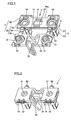
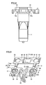
Fig. 1 is a perspective view showing a detection cell
(detection container) according to a first embodiment of
the present invention having a lid in an opening state;
Fig. 2 is a perspective view showing the detection
cell according to the first embodiment of the present
invention having the lid in a closed state as viewed along
arrow A in Fig. 1;
Fig. 3 is a perspective view showing a cell member
constituting the detection cell shown in Fig. 1;
Fig. 4 is a sectional view of the cell member taken
along the line 100-100 Fig. 3;
Fig. 5 is a sectional view of the cell member taken
along the line 200-200 Fig. 3;
Fig. 6 is a partially enlarged view of the cell
member shown in Fig. 3 as viewed along arrow B;
Fig. 7 is a sectional view of the cell member taken
along the line 300-300 Fig. 3;
Fig. 8 is a sectional view of the cell member taken
along the line 400-400 Fig. 3;
Fig. 9 is a perspective view showing a lid member
constituting the detection cell shown in Fig. 1;
Fig. 10 is a sectional view of the lid member taken
along the line 500-500 in Fig. 9;
Fig. 11 is a sectional view of the lid member taken
along the line 600-600 in Fig. 9;
Fig. 12 is a side elevational view showing a coupling
part of the lid member shown in Fig. 9 as viewed along
arrow C;
Figs. 13 to 15 are schematic diagrams for
illustrating gene detection through the detection cell
shown in Fig. 1;
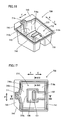
Fig. 16 is a perspective view showing a detection
cell packing container according to a second embodiment of
the present invention;
Fig. 17 is a plan view of the detection cell packing
container shown in Fig. 16;
Fig. 18 is a sectional view of the detection cell
packing container taken along the line 800-800 in Fig. 17;
Fig. 19 is a sectional view of the detection cell
packing container taken along the line 810-810 in Fig. 17;
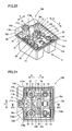
Fig. 20 is a perspective view showing the detection
cell packing container according to the second embodiment
in a state storing a detection cell;
Fig. 21 is a plan view of the detection cell packing
container storing the detection cell shown in Fig. 20;
Fig. 22 is a front elevational view of the detection
cell packing container storing the detection cell as
viewed along arrow H in Fig. 20;
Fig. 23 is a sectional view of the detection cell
packing container storing the detection cell taken along
the line 820-820 in Fig. 21;
Fig. 24 is a perspective view showing the detection
cell packing container storing the detection cell in a
state closed with a sheet; and
Figs. 25 and 26 are diagrams for illustrating an
operation of taking out the detection cell from the
detection cell packing container according to the second
embodiment of the present invention shown in Fig. 20.
DESCRIPTION OF THE PREFERRED EMBODIMENTS
Embodiments of the present invention are now
described with reference to the drawings.
(First Embodiment)
A first embodiment of the present invention is
described with reference to a disposable detection cell 1
employed for a gene amplifier/detector as an exemplary
container for an analyzer (detection container/reaction
container) according to the present invention. In other
words, the detection cell 1 according to the first
embodiment is employed for a gene amplifier/detector
injecting cancer derivation target nucleic acid (mRNAs)
into the detection cell 1, amplifying the same by LAMP
(loop-mediated isothermal amplification by Eiken Chemical
Co., Ltd.) and detecting the target genes (target nucleic
acids) by measuring turbidity of solutions following the
amplification. The LAMP is disclosed in U.S. Patent No.
6410278 in detail.
As shown in Fig. 1, the detection cell 1 according to
the first embodiment is constituted by integrally
combining two members, i.e., a cell member 10 and a lid
member 20 with each other. The cell member 10 consists of
light-transmittable heat-resistant transparent resin
(crystalline olefinic thermoplastic resin such as
polymethyl pentene (TPX), for example), and the lid member
20 consists of heat-resistant resin (high-density
polyethylene, for example). The detection cell 1 is
subjected to electron beam irradiation in a packed state
before shipment, so that decomposed enzyme of human saliva
or the like adherable in the process of manufacturing the
detection cell 1 exerts no bad influence on amplification
of genes. Polymethyl pentene, undiscolored by electron
beam irradiation, having high chemical resistance and high
heat resistance is a convenient material for the cell
member 10.
According to the first embodiment, two cell parts 13,
two hook engaging holes 14, two lid member engaging holes
15 and two registration recess portions 16 are integrally
formed on a base 10a in the cell member 10 constituting
the detection cell 1, as shown in Figs. 1 and 3. Each cell
part 13 includes a rectangular photoirradiation part
(sample storage part) 11 located on a lower portion and a
circular opening 12 located on an upper portion. The
photoirradiation part 11, injected with a sample and
irradiated with light in detection, has a rectangular
sectional shape as shown in Fig. 5. Each circular opening
12 has a cross-sectional area larger than that of the
rectangular photoirradiation part 11, as shown in Fig. 4.
As shown in Fig. 5, each photoirradiation part 11 is
provided with a pair of light transmission walls
consisting of an entrance wall 111 having a substantially
flat inner surface and an exit wall 112, also having a
substantially flat inner surface, arranged to be
parallelly opposed to the entrance wall 111 at an interval
of at least about 3 mm and not more than about 4 mm. The
interval between the entrance wall 111 and the exit wall
112 is so set to at least about 3 mm that change of
turbidity or the like of the sample can be easily detected
by photoirradiation. Further, the interval between the
entrance wall 111 and the exit wall 112 is so set to not
more than about 4 mm that the quantity of the sample
necessary for detection can be reduced. Further, both of
the entrance wall 111 and the exit wall 112 have
thicknesses of not more than about 0.5 mm. The entrance
wall 111 and the exit wall 112 are so formed with the
small thicknesses of not more than about 0. 5 mm that heat
can be efficiently transmitted to the sample.
Each photoirradiation part 11 is also provided with a
pair of side walls 113 and 114, having substantially flat
inner surfaces, oppositely arranged at an interval of at
least about 1.5 mm and not more than about 3 mm for
coupling the entrance wall 111 and the exit wall 112 with
each other. The interval between the pair of side walls
113 and 114 is so set to at least about 1.5 mm that light
can be easily applied to the entrance wall 111 and the
exist wall 112 located between the pair of side walls 113
and 114 in detection. Further, the interval between the
pair of side walls 113 and 114 is so set to not more than
about 3 mm that the quantity of the sample necessary for
detection can be reduced. Both of the side walls 113 and
114 have thicknesses of not more than about 0.5 mm. The
side walls 113 and 114 are so formed with the small
thicknesses of not more than about 0.5 mm that heat can be
efficiently transmitted to the sample. The entrance wall
111, the exit wall 112 and the pair of side walls 113 and
114 constitute the photoirradiation part 11 having the
substantially rectangular (oblong) inner shape shown in
Fig. 5.
The side walls 113 and 114 include projections 113a
and 114a projecting with respect to the surface of the
entrance wall 111 and projections 113b and 114b projecting
with respect to the surface of the exit wall 112
respectively. The projections 113a, 113b, 114a and 114b
have functions of preventing the surfaces of the entrance
wall 111 and the exit wall 112 from flawing when each cell
part 13 is set in a detector (not shown). If the
projections 113a, 113b, 114a and 114b remarkably project
with respect to the entrance wall 111 and the exist wall
112, however, the distances between the entrance wall 111
and the exit wall 112 and a warming part (not shown) of
the detector are increased to reduce warming efficiency.
In order to suppress reduction of the warming efficiency,
therefore, the quantities of projection of the projections
113a, 113b, 114a and 114b are preferably minimized. More
specifically, the quantities of projection of the
projections 113a, 113b, 114a and 114b with respect to the
entrance wall 111 and the exist wall 112 are preferably
set to about 0.2 mm to not more than about 0.3 mm.
In the section shown in Fig. 5, four corner portions
115 on the inner surfaces of each photoirradiation part
111 have a substantially arcuate curved shape with a
radius of curvature of not more than about 0.5 mm
(preferably at least about 0.1 mm and not more than about
0.3 mm). Thus, the inner surfaces of the corner portions
115 are so formed in the substantially arcuate curved
shape that bubbles hardly adhere to the corner portions
115 and a flowing state is improved when the sample or the
like is stirred, whereby stirring efficiency can be
improved. Further, the radius of curvature of the inner
surfaces of the corner portions 115 is so reduced to not
more than about 0.5 mm that the areas of the entrance wall
111 and the exist wall 112 can be remarkably inhibited
from reduction resulting from the arcuate curved shape of
the inner surfaces of the corner portions 115. When the
inner surfaces of the corner portions 115 are so formed as
to have a radius of curvature in the range of at least
about 0.1 mm and not more than about 0.3 mm, reduction of
the areas of the light transmission walls can be
remarkably suppressed while improving the stirring
efficiency.
Chamfers 113c and 114c are provided on the lowermost
portions of the projections 113a, 113b, 114a and 114b, as
shown in Fig. 6. Each cell part 13 can be smoothly set in
the detector (not shown) through these chamfers 113c and
114c.
In the cross section shown in Fig. 4, a bottom
surface part 116 of each photoirradiation part 11 of the
cell member 10 is formed in a substantially arcuate curved
shape. Thus, a level height allowing detection by
photoirradiation can be obtained also when the quantity of
the sample is small and the quantity of a liquid is also
small.
As shown in Figs. 3 and 7, the hook engaging holes 14
of the cell member 10 are provided with inclined parts 14a
for simplifying insertion of hook parts 32 of the lid
member 20 into the hook engaging holes 14 as described
later and engaging portions 14b engaging with the forward
ends of the hook parts 32. As shown in Figs. 3 and 8, the
lid member engaging holes 15 of the cell member 10 are
provided with engaging portions 15a engaging with the
forward ends of cell member engaging segments 42 of the
lid member 20 described later.
As shown in Fig. 9, the lid member 20 constituting
the detection cell 1 is constituted of a lid part 30, a
cell member mounting part 40 and coupling parts 50 for
coupling the lid part 30 and the cell member mounting part
40 with each other. The lid part 30 is integrally formed
with two closing parts 31, the two hook parts 32, a knob
part 33 and a position correcting part 34. The cell member
mounting part 40 is integrally formed with two cell member
mounting holes 41, the two cell member engaging segments
42, two registration projecting portions 43 and two
detector mounting parts 44.
The closing parts 31 of the lid part 30 are provided
on positions corresponding to the two openings 12 of the
cell member 10 (see Fig. 1). The closing parts 31 are
formed in a shape capable of closing the openings 12 (see
Fig. 4) of the two cell parts 13, as shown in Fig. 10.
Further, the two hook parts 32 are arranged to be
engageable with the two hook engaging holes 14 of the cell
member 10 (see Fig. 1) when the closing parts 31 are
closed, as shown in Fig. 9. The knob part 33 is provided
on the central portion of an end surface of the lid part
30. This knob part 33 is so provided that the user can
easily grasp the detection cell 1 when disposing the same
in the state shown in Fig. 2 after completion of detection.
The position correcting part 34 is elastically provided
between the two closing parts 31 of the lid part 30. This
position correcting part 34 has a function of correcting
the positions of the two closing parts 31 with respect to
the two openings 12.
As shown in Fig. 9, the two cell parts 13 of the cell
member 10 (see Fig. 1) are inserted into the cell member
mounting holes 41 of the cell member mounting part 40. The
two cell member engaging segments 42 are provided on the
central portion of the cell member mounting part 40 to be
opposed to each other at a prescribed interval as shown in
Fig. 9, and have a sectional shape with a tapered forward
end as shown in Fig. 11. The cell member engaging segments
42 engage with the engaging parts 15a (see Fig. 8) of the
two lid member engaging holes 15 of the cell member 10.
The two registration projecting portions 43 of the cell
member mounting part 40 are arranged on both ends of the
cell member mounting part 40 as shown in Fig. 9, to be
fitted into the two registration recess portions 16 (see
Fig. 3) of the cell member 10. The two detector mounting
parts 44 of the cell member mounting part 40 are provided
on the back surface of the cell member mounting part 40 as
shown in Fig. 9, in order to mount the detection cell 1 on
the detector (not shown). The detector mounting parts 44
are divided at the center from each other and have
projections 44a on side surfaces thereof, as shown in Fig.
11.
As shown in Fig. 12, each coupling part 50 is
constituted of two thick-walled portions 50a and a thin-walled
portion 50b located between the two thick-walled
portions 50a. The thin-walled portion 50b has a concavely
bent shape, to be easily bendable in a direction (along
arrow D in Fig. 12) for closing each closing part 31.
In order to assemble the detection cell 1 shown in
Fig. 1, the two cell parts 13 (see Fig. 3) of the cell
member 10 are inserted into the two cell member mounting
holes 41 (see Fig. 9) of the cell member mounting part 40
of the lid member 20 while the cell member engaging
segments 42 (see Fig. 9) of the cell member mounting part
40 are engaged with the engaging portions 15a (see Fig. 8)
of the lid member engaging holes 15 of the cell member 10.
Further, the two registration recess portions 16 (see Fig.
3) of the cell member 10 are fitted into the two
registration projecting portions 43 (see Fig. 9) of the
cell member mounting part 40. Thus, the detection cell 1
is integrally assembled.
When the closing parts 31 open in Fig. 1 are closed
as shown in Fig. 2, the two hook parts 32 of the lid part
30 engage with the corresponding hook engaging holes 14 of
the cell member 10 respectively. Thus, the closing parts
31 are held in the closed state.
Figs. 13 to 15 are schematic diagrams for
illustrating gene detection through the detection cell 1
according to the first embodiment. The gene detection
through the detection cell 1 according to the first
embodiment is now described with reference to Figs. 13 to
15. As hereinabove described, the detection cell 1
according to the first embodiment amplifies the cancer
derivation target nucleic acid (mRNAs) injected into the
same through the LAMP and detects the target genes (target
nucleic acids) by measuring turbidity of the solutions
following the amplification. As shown in Fig. 13, a
detector 201 employed for the gene detection through the
detection cell 1 according to the first embodiment
includes a reaction part (amplification part) 210, a
closing mechanism part 220 and a turbidity detection part
230 detecting liquid turbidity in the detection cell 1.
The reaction part 210 is provided with photoirradiation
grooves 211 for applying light to the detection cell 1.
The lid closing mechanism part 220 includes a shaft 221
rotated by a driving mechanism (not shown) and a lid
closing arm 222 mounted on the shaft 221 to be rotated
following rotation of the shaft 221. The turbidity
detection part 230 is constituted of an LED light source
part 230a mounted on a substrate 231a and a photodiode
part 230b mounted on another substrate 231b.
More specifically, the cell parts 13 of the detection
cell 1 are set on the reaction part 210 of the detector
201 while the lid part 30 of the detection cell 1 is
placed on the lid closing arm 222 of the lid closing
mechanism part 220. Samples suspected to contain the
target genes and reagents are injected into the
photoirradiation parts 11 of the cell parts 13 of the
detection cell 1, and the lid part 30 of the detection
cell 1 is closed. Referring to Fig. 13, the lid part 30 is
open immediately after injection of the samples and the
reagents into the cell parts 13. From this state, the lid
closing arm 222 mounted on the shaft 221 rotated by the
driving mechanism (not shown) is rotated about the shaft
221 along arrow in Fig. 13. Thus, the closing parts 31 of
the lid part 30 placed on the lid closing arm 222 are
rotated toward the openings 12 of the cell parts 13 to be
closed with respect to the openings 12 as shown in Fig. 14.
Once the closing parts 31 are closed, this closed state is
kept due to the engagement of the hook parts 32 of the lid
part 30 and the hook engaging holes 14 of the cell member
10, so that the closing parts 31 are prevented from
reopening. Thereafter the shaft 221 is oppositely rotated
so that the lid closing arm 222 mounted on the shaft 221
returns to the initial position as shown in Fig. 15. Thus,
the lid part 30 is closed.
After completion of the aforementioned lid closing
operation, liquids contained in the photoirradiation parts
11 of the cell parts 13 are warmed by the warming part
(not shown) from about 20°C to about 65°C, thereby
amplifying the target nucleic acide (mRNAs) by LAMP (gene
amplification) reaction. Whitening resulting from
amplification products formed following the amplification
is turbidimetrically detected through the turbidity
detection part 230. More specifically, light of about 1 mm
in diameter is applied from the LED light source part 230a
to the entrance walls 111 of the photoirradiation parts 11
of the cell parts 13 subjected to amplification along
arrow B (see Figs. 1 and 15) through the photoirradiation
grooves 211 of the reaction part 210. Then, the photodiode
part 230b receives the light outgoing from the exit walls
112 of the photoirradiation parts 11. Thus, the turbidity
of the liquids in the photoirradiation parts 11 of the
cell parts 13 subjected to amplification is measured. An
amplification rise time indicating the time up to sudden
increase of the numbers of copies of the target nucleic
acid (mRNAs) in the samples is detected from the measured
data on the basis of change of turbidity. The
concentrations of the target genes are calculated from the
amplification rise time on the basis of a previously
created calibration curve. In the calibration curve
showing the amplification rise time and the target gene
concentrations on the axes of abscissa and ordinate
respectively, the target gene concentrations are increased
as the amplification rise time is reduced in general. Thus,
gene (nucleic acid) detection is performed. After
completion of the gene detection, the user grasps the knob
part 33 of the detection cell 1 for disposing the
detection cell 1.
According to the first embodiment, as hereinabove
described, the cell member 10 and the lid member 20 are
integrally combined with each other for constituting the
detection cell 1 so that the cell member 10 and the lid
member 20 are integrally coupled with each other, whereby
no lid part 30 of the lid member 20 falls on another
detection cell 1. Thus, no samples in the other detection
cell 1 are contaminated due to a fall of the lid member 20.
According to the first embodiment, further, the hook
parts 32 and the hook engaging holes 14 are so provided
that the lid part 30 of the detection cell 1 can be easily
kept closed by engaging the hook parts 32 and the hook
engaging holes 14 with each other, whereby the lid part 30
can be prevented from opening by external force. Thus, the
samples contained in the cell parts 13 can be prevented
from contaminating other samples or reagents by opening of
the lid part 30. The hook parts 32 and the hook engaging
holes 14 are formed to engage with each other when the
closing parts 31 of the lid part 30 close the openings 12
of the cell parts 13, thereby keeping the openings 12 of
the cell parts 13 closed with the closing parts 31.
According to the first embodiment, the cell parts 13
are so provided with the photoirradiation parts 11
irradiated with light that the target genes can be
detected by externally applying light to the samples
contained in the photoirradiation parts 11 of the cell
parts 13.
According to the first embodiment, the cross-sectional
area of the openings 12 is rendered larger than
that of the photoirradiation parts 11 so that the samples
can be more easily injected into the openings 12 as
compared with openings having a small cross-sectional area.
Further, level heights necessary for measuring the samples
can be obtained by the photoirradiation parts 11 having
the small cross-sectional area also when the quantities of
the samples are small, whereby the samples having small
quantities can also be measured by photoirradiation.
Further, the openings 12 are so circularly shaped that the
same can be more easily closed with the closing parts 31
of the lid part 30 as compared with openings having a
rectangular shape or the like.
According to the first embodiment, the cell member 10
is provided with the two cell parts 13 while the lid part
30 is provided with the two closing parts 31 so that two
samples can be detected in parallel with each other,
whereby prompt detection can be performed.
According to the first embodiment, the elastic
position correcting part 34 is so provided between the two
closing parts 31 that the positions of the two closing
parts 31 can be easily properly corrected also when theses
positions are displaced from the two openings 12, whereby
the two openings 12 can be reliably closed with the
closing parts 31.
According to the first embodiment, the lid part 30 of
the lid member 30 is so provided with the knob part 33
that the user can easily dispose the detection cell 1 by
grasping the knob part 33 after completion of detection.
According to the first embodiment, as hereinabove
described, the pairs of side walls 13 and 14 having the
substantially flat inner surfaces are so provided that
voids necessary for detection by photoirradiation can be
formed between the pairs of side walls 113 and 114 also
when the intervals therebetween are reduced to some extent.
Thus, the intervals between the pairs of side walls 113
and 114 can be so reduced as to reduce the volumes of the
portions enclosed with the pairs of side walls 113 and 114,
the entrance walls 111 and the exit walls 112. Thus, the
quantities of samples necessary for detection can be so
reduced that the samples having small quantities can also
be detected.
According to the first embodiment, the inner surfaces
of the corner portions 115 formed on the intersections
between the pairs of side walls 113 and 114, the entrance
walls 111 and the exit walls 112 are formed to have the
substantially concave arcuate curved shape that bubbles
hardly adhere to the corner portions 115 and the flowing
state is improved when the samples or the like are stirred,
whereby stirring efficiency can be improved.
According to the first embodiment, the side walls 113
and 114 are provided with the projections 113a and 114a
projecting with respect to the surfaces of the entrance
walls 111 and the projections 113b and 114b projecting
with respect to the surfaces of the exit walls 112
respectively, whereby the surfaces of the entrance walls
111 and the exit walls 112 can be prevented from flawing
when the cell parts 13 are inserted into the reaction part
210 (see Fig. 13) of the detector 200.
According to the first embodiment, the chamfers 113c
and 114c are so provided on the lower ends of the
projections 113a, 113b, 114a and 114b of the pairs of side
walls 113 and 114 that the cell parts 13 can be smoothly
inserted into the reaction part 210 (see Fig. 13) of the
detector 200.
According to the first embodiment, the inner surfaces
of the bottom surface parts 116 is formed in the
substantially concave arcuate curved shape so that level
heights allowing detection by photoirradiation can be
obtained also when the samples are in small quantities and
the quantities of the liquids are small.
(Second Embodiment)
Figs. 16 to 19 are diagrams for illustrating the
structure of a detection cell packing container 700
according to a second embodiment of the present invention,
and Figs. 20 to 24 are diagrams for illustrating a state
of storing a detection cell 1 in the detection cell
packing container 700 according to the second embodiment
of the present invention. Figs. 25 and 26 are diagrams for
illustrating an operation of taking out the detection cell
1 from the detection cell packing container 700 according
to the second embodiment of the present invention shown in
Fig. 20. The detection cell 1 stored in the detection cell
packing container 700 according to the second embodiment
of the present invention is similar to the detection cell
1 (see Figs. 1 to 12) described with reference to the
aforementioned first embodiment. The structure of the
detection cell packing container 700 according to the
second embodiment of the present invention is now
described with reference to Figs. 16 to 19 and 24 to 26.
As shown in Figs. 16 to 18, the detection cell
packing container 700 according to the second embodiment
includes a recess portion 710 for storing the detection
cell 1, a concave first support part 720 enclosed with the
recess portion 710, a concave second support part 730
formed continuously with the first support part 720 and an
edge part 740 outwardly extending from an opening of the
recess portion 710. The recess portion 710, the first and
second support parts 720 and 730 and the edge part 740
constitute the body of the detection cell packing
container 700. The detection cell packing container 700
further includes a sheet 750 (Fig. 24). This detection
cell packing container 700, consisting of translucent
resin (polypropylene, for example) transmitting light to
some extent, is so constituted that storage of the
detection cell 1 can be externally visually recognized.
The inner side surfaces of the recess portion 710 of the
detection cell packing container 700 are inwardly inclined
downward so that a plurality of detection cell packing
containers 700 can be disposed in an overlapping state
after the detection cells 1 are taken out.
Portions of the recess portion 710 along arrows G and
F with reference to the first support part 720 are
referred to first and second recess portions 710b and 710c
respectively. The first recess portion 710b stores cell
parts 13. The second recess portion 710c is a space for
rendering the cell parts 13 upwardly movable while the
first support part 720 partially supports a lid member 20.
The first recess portion 710b has a larger cross-sectional
area than the cell parts 13. The length between the bottom
surface of the first recess portion 710b and the upper
surface of the second support part 730 is larger than the
length between the bottom surfaces of the cell parts 13
and openings 12. Therefore, photoirradiation parts 11
stored in the first recess portion 710b are not in contact
with the inner surfaces of the first recess portion 710b.
It is assumed that the expression "the second support part
730 supports a cell member 10" includes both of a case
where the second support part 730 supports the cell member
10 through a lid member 20 and a case where the second
support part 730 supports the cell member 10 without
through the lid member 20 in the following description.
A groove part 711 for receiving a knob part 33 of the
detection cell 1 in an operation of taking out the
detection cell 1 described later is formed on a prescribed
position of the recess portion 710 of the detection cell
packing container 700 (see Figs. 25 and 26). A
registration projecting portion 721 for registering the
stored detection cell 1 is formed on an upper portion of
the first support part 720. As shown in Figs. 16 to 18, an
end of the second support part 730 along arrow G is
connected to a side surface of the recess portion 710. The
width of the second support part 730 along arrow F is
smaller than that of the first support part 720 along
arrow F. The edge part 740 is upwardly inclined along
arrow E in Fig. 16. As shown in Figs. 16 to 19, a weld 741
is formed on the edge part 740 to enclose the recess
portion 710. This weld 741 is dissolved and solidified in
heat treatment for closing the detection cell packing
container 700 storing the detection cell 1 with the sheet
750 of polypropylene or the like thereby bonding the sheet
750 and the edge port 740 of the detection cell packing
container 700 to each other, as shown in Fig. 24. Further,
an oblique edge 742 is formed on a prescribed portion of
the edge part 740, as shown in Figs. 16 and 17. This
oblique edge 742 is so provided that the user can easily
grasp an end 750a of the sheet 750 for opening the
detection cell packing container 700 closed with the sheet
750 (see Fig. 24).
The structure for packing the detection cell 1 with
the detection cell packing container 700 according to the
second embodiment of the present invention is now
described with reference to Figs. 20 to 26. As shown in
Figs. 20 to 23, the detection cell 1 is horizontally
stored in the detection cell packing container 700. The
two cell parts 13 of the cell member 10 of this detection
cell 1 are coupled with each other by a cell coupling part
10a, while two closing parts 31 of the lid part 30 of the
detection cell 1 are coupled with each other by a lid
coupling part 30a. When the detection cell 1 is stored in
the detection cell packing container 700, the cell
coupling part 10a of the detection cell 1 is supported by
the second support part 730 of the detection cell packing
container 700 while a portion of the lid coupling part 30a
of the detection cell 1 closer to the cell coupling part
10a is supported by the first support part 720. When the
detection cell 1 is stored in the detection cell packing
container 700, the registration projecting portion 721 of
the first support part 720 enters a portion of the
detection cell 1 enclosed with the cell coupling part 10a,
the lid coupling part 30a and two coupling parts 50 of the
detection cell 1, as shown in Figs. 20 and 21. This
registration projecting portion 721 comes into contact
with the cell coupling part 10a of the detection cell 1,
thereby regulating movement of the detection cell 1 along
arrow E (see Fig. 20). Thus, the knob part 33 and two hook
parts 32 of the detection cell 1 are stored in the
detection cell packing container 700 without coming into
contact with the inner surfaces of the recess portion 710
of the detection cell packing container 700.
The outer side surfaces of the detection cell 1
located on ends of the cell member 10 along arrow G (see
Fig. 20) come into contact with the inner side surfaces of
the recess portion 710 of the detection cell packing
container 700, thereby regulating movement of the
detection cell 1 along arrow G. Further, the outer side
surfaces of the detection cell 1 located on both ends of
the cell member 10 along arrow F (see Fig. 20) come into
contact with the inner side surfaces of the recess portion
710 of the detection cell packing container 700, thereby
regulating movement of the detection cell 1 along arrow F.
The photoirradiation parts 11 of the cell parts 13 of the
detection cell 1 are stored in the detection cell packing
container 700 without coming into contact with the inner
surfaces of the recess portion 710 as shown in Figs. 21 to
23, due to the aforementioned regulation of movement along
arrows E, F and G.
The operation of taking out the detection cell 1 is
now described with reference to Figs. 20, 23, 25 and 26.
According to the second embodiment, the detection cell 1
is shipped in the state stored in the detection cell
packing container 700 closed with the sheet 750 (see Fig.
24). Therefore, the user must take out the detection cell
1 from the detection cell packing container 700 in order
to use the same.
In this operation of taking out the detection cell 1,
the user wears gloves on both hands for holding the
detection cell packing container 700 with the first hand
while grasping the end 750a of the sheet 750 (see Fig. 24)
closing the detection cell packing container 700 and
opening the same with the second hand. He/she downwardly
presses the knob part 33 of the detection cell 1 along
arrow I in Figs. 20 and 23 with a finger of the first hand
not holding the detection cell packing container 700. Thus,
the cell member 10 of the detection cell 1 is upwardly
rotated along arrow J in Figs. 23, 25 and 26 about the
back surface of the lid coupling part 30a of the lid part
30 coming into contact with the first support part 720,
i.e., while the first support part 720 supports the lid
part 30, as shown in Figs. 25 and 26. In the state shown
in Figs. 25 and 26, the lid part 30 partially enters the
second recess portion 710c and a prescribed portion of the
knob part 33 of the detection cell 1 comes into contact
with a side surface 720a of the first support part 720
while the two hook parts 32 of the detection cell 1 come
into contact with a side surface 710a (see Fig. 26) of the
recess portion 710. In the state shown in Figs. 25 and 26,
further, the detection cell 1 is inclined with respect to
the detection cell packing container 700 while the cell
member 10 of the detection cell 1 upwardly projects from
an opening of the recess portion 710. In the process of
this rotation of the detection cell 1, the
photoirradiation parts 11 of the cell parts 13 of the
detection cell 1 are not in contact with the inner
surfaces of the recess portion 710, as shown in Figs. 23
and 25. From this inclined state of the detection cell 1,
the user grasps both longitudinal side surfaces of the
upwardly projecting cell member 10 of the detection cell 1
with the second hand not holding the detection cell
packing container 700 for taking out the detection cell 1
from the detection cell packing container 700. Then,
he/she sets the detection cell 1 on the reaction part
(amplification part) 210 of the detector 201 employed for
the gene detection according to the first embodiment shown
in Fig. 13.
According to the second embodiment, as hereinabove
described, the detection cell packing container 700 is
constituted of the recess portion 710 for storing the
detection cell 1, the concave second support part 730
supporting the cell coupling part 10a of the cell member
10 and the concave first support part 720 partially
supporting the portion of the lid coupling part 30a of the
lid part 30 closer to the cell coupling part 10a while the
first and second support parts 720 and 730 are formed to
support the detection cell 1 so that the photoirradiation
parts 11 of the cell parts 13 are not in contact with the
inner surfaces of the recess portion 710 of the detection
cell packing container 700, whereby the cell parts 13 of
the detection cell 1 can be prevented from coming into
contact with the inner surfaces of the detection cell
packing container 700 and being flawed. According to the
second embodiment, further, the first and second support
parts 720 and 730 are so constituted that the detection
cell 1 can be inclined and taken out by downwardly
applying pressing force to the knob part 33 of the
detection cell 1 while supporting the detection cell 1,
whereby the user can easily take out the detection cell 1
from the detection cell packing container 700.
Although the present invention has been described and
illustrated in detail, it is clearly understood that the
same is by way of illustration and example only and is not
to be taken by way of limitation, the spirit and scope of
the present invention being limited only by the terms of
the appended claims.
For example, while the two members, i.e., the cell
member 10 and the lid member 20 are integrally combined
with each other for constituting the detection cell 1
having the integrally coupled lid in the aforementioned
first embodiment, the present invention is not restricted
to this but a detection cell having an integrally coupled
lid may alternatively be formed by a single member.
While the openings 12 of the cell parts 13 are
circularly formed in the aforementioned first embodiment,
the present invention is not restricted to this but the
openings 12 of the cell parts 13 may alternatively have a
shape, such as a rectangular shape, other than the
circular shape.
While the hook parts 32 and the hook engaging holes
14 exemplarily constitute a closing state holding part for
keeping the lid part 30 in the closed state in the
aforementioned first embodiment, the present invention is
not restricted to this but a closing state holding part
constituted of elements other than the hook parts 32 and
the hook engaging holes 14 may alternatively be employed.
While the detection cell 1 (detection container)
according to the present invention is applied to that for
amplifying target genes by the LAMP in the aforementioned
first embodiment, the present invention is not restricted
to this but may alternatively be applied to a detection
container amplifying target genes by polymerase chain
reaction (PCR) or ligase chain reaction (LCR). Further,
the detection cell according to the present invention may
be applied to that for immune agglutination or blood-clotting
reaction, for example, other than gene
amplification.
While the first embodiment has been described with
reference to the detection container for amplifying the
target nucleic acids in the cell parts 13 and detecting
the nucleic acids by irradiating the amplified samples
with light, the present invention is not restricted to
this but may be applied to a detection container for
storing samples subjected to amplification of target
nucleic acids in another container and irradiating the
samples with light thereby detecting the nucleic acids.
The detection container according to the
aforementioned first embodiment may be a reaction
container for amplifying target nucleic acids in a
container body. In this case, the samples subjected to
amplification of the target nucleic acids in the reaction
container may be sucked by passing suction needles through
the closing parts 31 and discharged into another detection
container to be thereafter detected. When the detection
container according to the aforementioned first embodiment
is employed as the reaction container, the cell parts 13
may not be transparent.
While the inner surfaces of the corner portions 115
of the photoirradiation parts 11 have the concave arcuate
curved shape in the aforementioned first embodiment, the
present invention is not restricted to this but the inner
surfaces of the corner portions 115 of the
photoirradiation parts 11 may alternatively have a curved
shape other than the concave arcuate shape. For example,
the inner surfaces of the corner portions 115 of the
photoirradiation parts 11 may have a convex arcuate curved
shape.
While the bottom surface parts 116 of the
photoirradiation parts 11 have the concave arcuate shape
in the aforementioned first embodiment, the present
invention is not restricted to this but the bottom surface
parts 116 of the photoirradiation parts 11 may
alternatively have a flat shape or the like.
While the detection cell 1 is taken out from the
detection cell packing container 700 by downwardly
pressing the knob part 33 of the detection cell 1 in the
aforementioned second embodiment, the present invention is
not restricted to this but a detection cell having no knob
part may be taken out from the detection cell packing
container 700 by downwardly pressing a portion of the
detection cell opposite to a cell coupling part.
While the first and second recess portions 710b and
710c are continuous with each other in the aforementioned
second embodiment, the present invention is not restricted
to this but the first and second recess portions 710b and
710c may alternatively be separated through the first
support part 720 or the like.
While the first support part 720 partially supports
the lid part 30 in the aforementioned second embodiment,
the present invention is not restricted to this but the
first support part 720 may alternatively support the
coupling parts 50.
While the second support part 730 supports the cell
coupling part 10a in the aforementioned second embodiment,
the present invention is not restricted to this but the
second support part 730 may alternatively support portions
of the cell member 10 located outward beyond the two cell
parts 13.