EP1507987B1 - Fail-safe concept for a servo-assisted electromechanical brake - Google Patents
Fail-safe concept for a servo-assisted electromechanical brake Download PDFInfo
- Publication number
- EP1507987B1 EP1507987B1 EP03735493A EP03735493A EP1507987B1 EP 1507987 B1 EP1507987 B1 EP 1507987B1 EP 03735493 A EP03735493 A EP 03735493A EP 03735493 A EP03735493 A EP 03735493A EP 1507987 B1 EP1507987 B1 EP 1507987B1
- Authority
- EP
- European Patent Office
- Prior art keywords
- brake
- fault
- control system
- movement state
- braked
- Prior art date
- Legal status (The legal status is an assumption and is not a legal conclusion. Google has not performed a legal analysis and makes no representation as to the accuracy of the status listed.)
- Expired - Lifetime
Links
- 230000033001 locomotion Effects 0.000 claims abstract description 31
- 230000008859 change Effects 0.000 claims description 17
- 238000000034 method Methods 0.000 claims description 14
- 238000004891 communication Methods 0.000 claims description 7
- 238000001514 detection method Methods 0.000 claims description 7
- 230000008569 process Effects 0.000 claims description 5
- 230000004913 activation Effects 0.000 claims 1
- 238000006073 displacement reaction Methods 0.000 description 10
- 230000001960 triggered effect Effects 0.000 description 7
- 238000005259 measurement Methods 0.000 description 6
- 230000007257 malfunction Effects 0.000 description 5
- 238000004092 self-diagnosis Methods 0.000 description 4
- 230000002123 temporal effect Effects 0.000 description 4
- 230000008901 benefit Effects 0.000 description 3
- 230000005540 biological transmission Effects 0.000 description 3
- 238000006243 chemical reaction Methods 0.000 description 3
- 230000000295 complement effect Effects 0.000 description 3
- 230000007547 defect Effects 0.000 description 3
- 239000012530 fluid Substances 0.000 description 3
- 238000012423 maintenance Methods 0.000 description 3
- 238000005086 pumping Methods 0.000 description 3
- 244000290594 Ficus sycomorus Species 0.000 description 2
- 239000003990 capacitor Substances 0.000 description 2
- 238000013461 design Methods 0.000 description 2
- 238000011161 development Methods 0.000 description 2
- 230000018109 developmental process Effects 0.000 description 2
- 238000010586 diagram Methods 0.000 description 2
- 230000000694 effects Effects 0.000 description 2
- 238000004146 energy storage Methods 0.000 description 2
- 238000007667 floating Methods 0.000 description 2
- 230000007246 mechanism Effects 0.000 description 2
- 238000003199 nucleic acid amplification method Methods 0.000 description 2
- 238000003825 pressing Methods 0.000 description 2
- 240000005001 Paeonia suffruticosa Species 0.000 description 1
- 235000003889 Paeonia suffruticosa Nutrition 0.000 description 1
- 238000004026 adhesive bonding Methods 0.000 description 1
- 230000000903 blocking effect Effects 0.000 description 1
- 239000000969 carrier Substances 0.000 description 1
- 230000006835 compression Effects 0.000 description 1
- 238000007906 compression Methods 0.000 description 1
- 238000010276 construction Methods 0.000 description 1
- 230000002950 deficient Effects 0.000 description 1
- 230000001066 destructive effect Effects 0.000 description 1
- 238000003745 diagnosis Methods 0.000 description 1
- 238000005516 engineering process Methods 0.000 description 1
- 238000011156 evaluation Methods 0.000 description 1
- 230000002349 favourable effect Effects 0.000 description 1
- 239000000446 fuel Substances 0.000 description 1
- 230000002035 prolonged effect Effects 0.000 description 1
- 230000009467 reduction Effects 0.000 description 1
- 230000002441 reversible effect Effects 0.000 description 1
- 238000005096 rolling process Methods 0.000 description 1
- 210000002023 somite Anatomy 0.000 description 1
- 230000003068 static effect Effects 0.000 description 1
Images


Classifications
-
- B—PERFORMING OPERATIONS; TRANSPORTING
- B60—VEHICLES IN GENERAL
- B60T—VEHICLE BRAKE CONTROL SYSTEMS OR PARTS THEREOF; BRAKE CONTROL SYSTEMS OR PARTS THEREOF, IN GENERAL; ARRANGEMENT OF BRAKING ELEMENTS ON VEHICLES IN GENERAL; PORTABLE DEVICES FOR PREVENTING UNWANTED MOVEMENT OF VEHICLES; VEHICLE MODIFICATIONS TO FACILITATE COOLING OF BRAKES
- B60T17/00—Component parts, details, or accessories of power brake systems not covered by groups B60T8/00, B60T13/00 or B60T15/00, or presenting other characteristic features
- B60T17/18—Safety devices; Monitoring
- B60T17/22—Devices for monitoring or checking brake systems; Signal devices
-
- B—PERFORMING OPERATIONS; TRANSPORTING
- B60—VEHICLES IN GENERAL
- B60T—VEHICLE BRAKE CONTROL SYSTEMS OR PARTS THEREOF; BRAKE CONTROL SYSTEMS OR PARTS THEREOF, IN GENERAL; ARRANGEMENT OF BRAKING ELEMENTS ON VEHICLES IN GENERAL; PORTABLE DEVICES FOR PREVENTING UNWANTED MOVEMENT OF VEHICLES; VEHICLE MODIFICATIONS TO FACILITATE COOLING OF BRAKES
- B60T13/00—Transmitting braking action from initiating means to ultimate brake actuator with power assistance or drive; Brake systems incorporating such transmitting means, e.g. air-pressure brake systems
- B60T13/74—Transmitting braking action from initiating means to ultimate brake actuator with power assistance or drive; Brake systems incorporating such transmitting means, e.g. air-pressure brake systems with electrical assistance or drive
- B60T13/741—Transmitting braking action from initiating means to ultimate brake actuator with power assistance or drive; Brake systems incorporating such transmitting means, e.g. air-pressure brake systems with electrical assistance or drive acting on an ultimate actuator
-
- B—PERFORMING OPERATIONS; TRANSPORTING
- B60—VEHICLES IN GENERAL
- B60T—VEHICLE BRAKE CONTROL SYSTEMS OR PARTS THEREOF; BRAKE CONTROL SYSTEMS OR PARTS THEREOF, IN GENERAL; ARRANGEMENT OF BRAKING ELEMENTS ON VEHICLES IN GENERAL; PORTABLE DEVICES FOR PREVENTING UNWANTED MOVEMENT OF VEHICLES; VEHICLE MODIFICATIONS TO FACILITATE COOLING OF BRAKES
- B60T2270/00—Further aspects of brake control systems not otherwise provided for
- B60T2270/40—Failsafe aspects of brake control systems
- B60T2270/414—Power supply failure
-
- B—PERFORMING OPERATIONS; TRANSPORTING
- B60—VEHICLES IN GENERAL
- B60T—VEHICLE BRAKE CONTROL SYSTEMS OR PARTS THEREOF; BRAKE CONTROL SYSTEMS OR PARTS THEREOF, IN GENERAL; ARRANGEMENT OF BRAKING ELEMENTS ON VEHICLES IN GENERAL; PORTABLE DEVICES FOR PREVENTING UNWANTED MOVEMENT OF VEHICLES; VEHICLE MODIFICATIONS TO FACILITATE COOLING OF BRAKES
- B60T2270/00—Further aspects of brake control systems not otherwise provided for
- B60T2270/82—Brake-by-Wire, EHB
-
- B—PERFORMING OPERATIONS; TRANSPORTING
- B60—VEHICLES IN GENERAL
- B60T—VEHICLE BRAKE CONTROL SYSTEMS OR PARTS THEREOF; BRAKE CONTROL SYSTEMS OR PARTS THEREOF, IN GENERAL; ARRANGEMENT OF BRAKING ELEMENTS ON VEHICLES IN GENERAL; PORTABLE DEVICES FOR PREVENTING UNWANTED MOVEMENT OF VEHICLES; VEHICLE MODIFICATIONS TO FACILITATE COOLING OF BRAKES
- B60T2270/00—Further aspects of brake control systems not otherwise provided for
- B60T2270/83—Control features of electronic wedge brake [EWB]
-
- F—MECHANICAL ENGINEERING; LIGHTING; HEATING; WEAPONS; BLASTING
- F16—ENGINEERING ELEMENTS AND UNITS; GENERAL MEASURES FOR PRODUCING AND MAINTAINING EFFECTIVE FUNCTIONING OF MACHINES OR INSTALLATIONS; THERMAL INSULATION IN GENERAL
- F16D—COUPLINGS FOR TRANSMITTING ROTATION; CLUTCHES; BRAKES
- F16D65/00—Parts or details
- F16D65/38—Slack adjusters
- F16D2065/386—Slack adjusters driven electrically
-
- F—MECHANICAL ENGINEERING; LIGHTING; HEATING; WEAPONS; BLASTING
- F16—ENGINEERING ELEMENTS AND UNITS; GENERAL MEASURES FOR PRODUCING AND MAINTAINING EFFECTIVE FUNCTIONING OF MACHINES OR INSTALLATIONS; THERMAL INSULATION IN GENERAL
- F16D—COUPLINGS FOR TRANSMITTING ROTATION; CLUTCHES; BRAKES
- F16D2121/00—Type of actuator operation force
- F16D2121/18—Electric or magnetic
- F16D2121/24—Electric or magnetic using motors
-
- F—MECHANICAL ENGINEERING; LIGHTING; HEATING; WEAPONS; BLASTING
- F16—ENGINEERING ELEMENTS AND UNITS; GENERAL MEASURES FOR PRODUCING AND MAINTAINING EFFECTIVE FUNCTIONING OF MACHINES OR INSTALLATIONS; THERMAL INSULATION IN GENERAL
- F16D—COUPLINGS FOR TRANSMITTING ROTATION; CLUTCHES; BRAKES
- F16D2123/00—Multiple operation forces
-
- F—MECHANICAL ENGINEERING; LIGHTING; HEATING; WEAPONS; BLASTING
- F16—ENGINEERING ELEMENTS AND UNITS; GENERAL MEASURES FOR PRODUCING AND MAINTAINING EFFECTIVE FUNCTIONING OF MACHINES OR INSTALLATIONS; THERMAL INSULATION IN GENERAL
- F16D—COUPLINGS FOR TRANSMITTING ROTATION; CLUTCHES; BRAKES
- F16D2125/00—Components of actuators
- F16D2125/18—Mechanical mechanisms
- F16D2125/20—Mechanical mechanisms converting rotation to linear movement or vice versa
- F16D2125/34—Mechanical mechanisms converting rotation to linear movement or vice versa acting in the direction of the axis of rotation
- F16D2125/40—Screw-and-nut
-
- F—MECHANICAL ENGINEERING; LIGHTING; HEATING; WEAPONS; BLASTING
- F16—ENGINEERING ELEMENTS AND UNITS; GENERAL MEASURES FOR PRODUCING AND MAINTAINING EFFECTIVE FUNCTIONING OF MACHINES OR INSTALLATIONS; THERMAL INSULATION IN GENERAL
- F16D—COUPLINGS FOR TRANSMITTING ROTATION; CLUTCHES; BRAKES
- F16D2125/00—Components of actuators
- F16D2125/18—Mechanical mechanisms
- F16D2125/44—Mechanical mechanisms transmitting rotation
- F16D2125/46—Rotating members in mutual engagement
- F16D2125/52—Rotating members in mutual engagement with non-parallel stationary axes, e.g. worm or bevel gears
-
- F—MECHANICAL ENGINEERING; LIGHTING; HEATING; WEAPONS; BLASTING
- F16—ENGINEERING ELEMENTS AND UNITS; GENERAL MEASURES FOR PRODUCING AND MAINTAINING EFFECTIVE FUNCTIONING OF MACHINES OR INSTALLATIONS; THERMAL INSULATION IN GENERAL
- F16D—COUPLINGS FOR TRANSMITTING ROTATION; CLUTCHES; BRAKES
- F16D2125/00—Components of actuators
- F16D2125/18—Mechanical mechanisms
- F16D2125/58—Mechanical mechanisms transmitting linear movement
- F16D2125/66—Wedges
-
- F—MECHANICAL ENGINEERING; LIGHTING; HEATING; WEAPONS; BLASTING
- F16—ENGINEERING ELEMENTS AND UNITS; GENERAL MEASURES FOR PRODUCING AND MAINTAINING EFFECTIVE FUNCTIONING OF MACHINES OR INSTALLATIONS; THERMAL INSULATION IN GENERAL
- F16D—COUPLINGS FOR TRANSMITTING ROTATION; CLUTCHES; BRAKES
- F16D2127/00—Auxiliary mechanisms
- F16D2127/08—Self-amplifying or de-amplifying mechanisms
- F16D2127/10—Self-amplifying or de-amplifying mechanisms having wedging elements
Definitions
- the present invention relates to a fault-safety concept for an electromechanical brake with self-boosting, in particular a control system for realizing such a fault-safety concept.
- Electromechanical brakes are known per se, for example from the DE 198 19 564 C2 .
- Such electromechanical brakes with self-boosting have the advantage that an actuating force generated by an electric actuator is amplified in a purely mechanical way without the introduction of auxiliary forces, so that the proportion of Aktuatorkraft required to cause a desired frictional force between the brake and the brake disc in the Compared to conventional brakes is drastically reduced.
- the control effort in such brakes compared to known hydraulic brake systems, however, is relatively high. Furthermore, the legislator has put very strict conditions on the reliability of brakes in general.
- the object of the present invention is to provide a fault-safety concept for electromechanical brakes with self-boosting in order to increase the fail-safety of such a brake.
- fatal consequences for the device to be braked should be avoided if an error occurs.
- the state of motion of the vehicle is determined, for example, on the basis of the angular velocity of a brake disc associated with the brake.
- the movement state of the vehicle is further specified on the basis of the temporal change of the friction force or of the friction torque between the brake and a brake disc associated with the brake in order, for example, to reliably detect the stoppage of a vehicle.
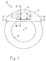
- FIGS. 1 and 2 show an electromechanical brake 10 designed as a disk brake with a housing 12 and a brake disk 14 rotatable about an axis A.
- the brake 10 has a first friction lining 16 which is fixedly connected to the front of serving as a pad carrier wedge 18, for example by gluing.
- the wedge 18 On its rear side, the wedge 18 has a wedge surface 20 or 20 'for each direction of rotation of the brake disk 14, both of which are arranged at an angle ⁇ to the brake disk 15 and are supported on complementary wedge surfaces 21, 21' of a block-shaped abutment 22.
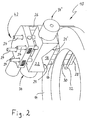
- the abutment 22 is supported by four threaded bolts 24 on a brake caliper 26 (s. FIG. 2 and 5 ), which spans the brake disk 14 and has an arm 28, which is executed to the axis of rotation.
- the arm 28 serves to support a second friction lining 30, which is fastened in a customary manner on a lining carrier plate 32, which rests against the inner side of the arm 28 facing the brake disk 14.
- the actuating force of the brake 10 is generated by an electric actuator, which comprises two, here designed as linear actuators drives 34 and 34 '.
- Each drive 34, 34 ' comprises an electric motor 36, 36' and a push rod 38, 38 'driven by it, which is in operative connection with the wedge 18.
- each electric motor 36, 36 ' has an integrated spindle nut (not shown) and the push rods 38, 38' are each formed as cooperating with the spindle nut spindle.
- An unillustrated rotary encoder in each electric motor 36, 36 ' allows the determination of the exact position of the associated push rod 38, 38' based on the rotations performed by the electric motor 36 or 36 'and the pitch of the spindle drive.
- the wedge 18 and the abutment 22 are part of a self-reinforcing device for amplifying the actuation force generated by the drives 34, 34 '.
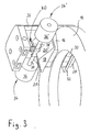
- the free ends of the push rods 38 and 38 'in a present on the back of the wedge 18 receptacle 40 are mounted so that a translational movement of the push rods 38, 38' to a corresponding displacement of the wedge 18 to the left or right leads (s. Figures 3 and 4 ).
- the wedge 18 is supported via its one wedge surface 20 and 20 'on the associated complementary wedge surface 21 or 21' of the abutment 22 and moves not only to the left or right but also to the brake disc 14.
- a reaction force is generated which is transmitted from the friction lining 16 via the wedge 18 and the abutment 22 to the brake caliper 26.
- the latter is floating on the housing 12 of the brake 10 and is displaced by the said reaction force until the second friction lining 30 also bears against the brake disk 14 (floating caliper principle).
- Each further translational displacement of the wedge 18 in the actuating direction now leads to a stronger pressing of the two friction linings 16 and 30 to the brake disk 14 and thus to the desired braking operation.
- a release of the brake is done by moving back the wedge 18 in his in FIG. 4 Played starting position.
- the wedge surfaces 20, 20 'and / or the abutment surfaces 21, 21' for example, with rolling elements (not shown) may be provided.
- the receptacle 40 is formed so that the wedge 18 can move in the direction of the brake disc 14 and away from it, without the push rods 38, 38 'join this movement.
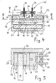
- an adjusting device 42 In order for the brake 10 to be able to compensate for a wear-out friction lining, an adjusting device 42, generally designated 42, is present (see FIG. FIG. 2 ).
- This consists (s. FIGS. 4 and 5 ) from a rotor 44 which drives a worm shaft 46 which meshes with four gears 48.
- the gears 48 are mounted in the caliper 26 and each have an internal thread which is in engagement with an associated threaded bolt 24 which are fixedly connected to the abutment 22 (s. FIG. 5 ).
- the gears therefore act as spindle nuts of a spindle drive, while the threaded bolts 24 represent the spindle rods.
- the adjusting device 42 can thus increase the distance of the abutment 22 from the brake caliper 26, ie, move the abutment 22 in the direction of the brake disk 14. In this way, the clearance of the brake 10, ie the distance between the brake disc 14 and the friction lining surface present when the brake is released, can be kept constant.
- the brake 10 will be designed so that when a large clearance is detected during braking, a control activates the adjusting device 42 when the brake is released to reduce the clearance back to the design value.
- the adjusting device is preferably designed to be self-locking in order to prevent inadvertent adjustment of the clearance. Meanwhile, as explained later in detail, the self-locking of the adjusting device 42 can be canceled in the event of a fault.
- the adjusting device 42 described here represents a possibility to compensate for a friction lining wear.
- Other embodiments of the brake 10 may instead of the Electric motor 44 have an ultrasonic motor, a stepper, a stepper motor or other suitable drive.
- the transmission of the adjusting device 42 may be designed differently, for example as a harmonic drive transmission.
- four threaded bolts 24 must be present, but it may be more or less threaded bolt and there are also other means than threaded bolts conceivable to achieve the described relative displacement of the abutment 22.
- the adjusting device also has special significance as a means (actuator) for carrying out a so-called emergency solution.
- actuator for carrying out a so-called emergency solution.
- the self-energizing device has a wedge surface 20 or 20 'for each direction of rotation of the brake disk 14, which is supported on a complementary surface 21 or 21' of the abutment 22.
- the brake disc 14 is arranged at an effective wedge angle ⁇ .
- FIG. 6 are indicated by arrows the forces acting on the wedge 18.
- the input force F A acts on the wedge 18 in a braking operation, is generated by the two drives 34, 34 '.
- the degree of self-amplification of the introduced force F A depends only on the pitch angle ⁇ .
- the brake 10 'needs to be in contact with the friction lining 16 with the brake disc 14 is - for further braking no input force F A more.
- This equilibrium state is therefore also referred to as the point of optimal self-reinforcement. If ⁇ is smaller than tan ⁇ , a positive input force F A must be present in order to maintain braking.
- the brake 10 In order for the input force F A to be small, it is desirable to operate the brake 10 in a range where the friction coefficient ⁇ is at least approximately equal to the tangent of the pitch angle ⁇ (hereinafter referred to as "normal case"). In this range of low actuating forces, the two drives 34 and 34 'work against each other, ie the two drives 34, 34' via the push rods 38, 38 'mutually opposing forces in the wedge 18 a. The opposing forces are dimensioned such that an excess of force results in the direction in which the wedge 18 is to be displaced upon actuation.
- both drives 34, 34 ' are reversible, ie their direction of actuation can be reversed.
- the actuator of the brake 10 is no longer free of play.
- the friction coefficient ⁇ can change relatively strongly as a function of the load on the brake.
- Each change in the coefficient of friction during a braking operation leads to a change in the friction force F F and thus to a changing deceleration of the component of the brake to be braked, which in the present case is formed by the brake disk 14.
- the disc brake shown is equipped with a device for determining the friction torque.
- the means for determining the friction torque comprises first means for measuring the friction force and optionally second means for determining between the brake disc and the friction lining acting normal force. For example, while the frictional force is measured by a sensor that measures the initiated during braking from the caliper into the chassis force.
- This force leads to deformations, which can be measured by suitable sensors.
- a sensor is, for example, a strain gauge, which is attached to a suitable location, for example to the holder of the caliper on the chassis.
- the force acting between the brake disk and the friction lining and directed normal to the brake disk can be determined.
- the coefficient of friction can be determined. In this way, it is possible to check the plausibility of the measured coefficient of friction and possible disturbances, in particular mechanical disturbances such. in the friction combination covering / disc (oily or vitrifying of the coverings, etc.) or in the saddle guides, discover using a corresponding coefficient of friction or a change in the coefficient of friction.
- Targeted changes in the frictional torque can be performed quickly and accurately with the brake system presented.
- the specifications for this come from a central control unit 72, which implements functions such as the vehicle dynamics control or a brake assist.
- the device for determining the friction torque may have first means for determining the actuator force and second means for determining the normal force acting between the brake disk and the friction lining.
- the force directed normal to the brake disc is therefore also determined here in order to improve the control dynamics and thus the overall quality of the brake control.
- the actuator force applied during braking is determined. This allows a more compact construction of the brake because no removed, for example, on the brake carrier mounted sensor for measuring the friction force is required more.
- the friction torque is determined indirectly, without the braking force has to be measured directly.
- the friction torque M Fi can be determined from the knowledge of the normal force F N and the actuator force F A.
- the actuator force can be measured directly, preferably with a force sensor arranged in the force flow of the actuator force, which can be, for example, a strain gauge.
- the force sensor can detect the reaction force with which an electric motor associated with the actuator is supported on the housing of the actuator or the brake.
- the force sensor can also be arranged at the point at which the Aktuatorkraft is introduced into the wedge of the wedge assembly.
- a force sensor can be arranged in or on a force transmission means of the actuator, for example on a spindle or a pull or push rod.
- the Aktuatorkraft does not have to be measured directly, but can be determined indirectly, for example, from the motor current of the electric motor associated with the actuator.
- the motor current is a measure of the torque output by the engine, which is converted, for example by a spindle drive in an axial force.
- the motor current I M1 or I M2 (see. Fig. 8 ) is therefore proportional to generated actuator force. For not too high demands on the actuation dynamics is a Such indirect determination of the actuator force is a suitable and favorable solution.
- the normal to the brake disc directed force can be measured by means disposed in the force flow of the normal force sensor.
- a measurement of forces near the place of origin is advantageous in order to avoid a falsification of the measurement signals by inertial masses.
- the normal force can also be determined indirectly, e.g. from the amount of displacement of the wedge assembly that occurs during a given braking.
- the normal force leads to a widening of the caliper of the disc brake and to a compression of the friction linings, to a lesser extent, also of the brake disc.
- These elasticities of the brake are compensated by a corresponding displacement of the wedge in the direction of actuation.
- zero position denotes the position of the friction linings in which the so-called clearance has just been overcome, the friction linings rest force-free against the brake disk, then the normal force or its change can be calculated from the extent of displacement of the wedge in the direction of actuation.
- the spring characteristic of the system brake (saddle, pads, disc) can be linearized in the respective operating point, thus the normal force in the respective operating point is directly proportional to the displacement of the wedge.
- the displacement of the wedge x1 or x2 can either be measured directly or it can be determined from the operating data of the actuator. For example, it is possible from the motor rotation angle of the The electric motor associated with the actuator to calculate the displacement of the wedge, at least when the electric motor acts on the wedge via a pitch-accurate feed system.
- the widening of the brake caliper can be determined with a commercially available position measuring system. Since the relationship between the widening of the caliper as a function of the acting normal force for practical purposes is linear or at least reproducible, the measurement of the widening of the brake caliper is another way to determine the normal force F N.
- the normal force is an auxiliary variable whose determination serves to improve the dynamics of the control, since the direct measurement of the friction torque due to the required Störssennfilterung can not be done quickly enough. In other words, the current value of the friction torque is available only with a certain delay.
- the per se possible highly dynamic actuation of an electromechanical brake requires, if the advantages of such a highly dynamic actuation to be exploited, a correspondingly high dynamic control, which is not possible by means of Reibkrafttul for the reasons already outlined above.
- the determination of the normal force acting as an auxiliary variable can be done quickly and accurately, for example, as already mentioned, by measuring the position of the wedge.
- the position of the wedge is, provided that the friction linings rest against the brake disk, in the linearized operating point proportional to the widening of the caliper and thus to the normal force F N. If, during operation of the brake, triggered, for example, by an ABS control process, the friction torque of the brake can be reduced by a certain amount, the control can calculate the required new wedge position and set very quickly by means of the actuator. A check of the actual friction torque is then carried out by the Reibkrafttician.
- the wear of the friction linings during operation of the brake leads to a change in the zero position.
- the zero position must therefore be detected again and again, if necessary, by the brake control.
- a simple way to determine the zero position is the Reibkraft spot.
- the frictional force increases abruptly in the moment in which the friction lining touches the brake disc.
- the wedge position at which the friction lining and the brake disk come into contact with each other can be easily detected.
- the local control unit or the main control unit 80 evaluates the signals received and in particular makes a comparison between a predetermined setpoint of the friction force and the actual actual value of the friction force. According to this evaluation of the signals, the drives 34, 34 'are controlled by the control unit so that an increase or decrease of the actual value of the friction force is achieved by displacement of the wedge 18 in or against the direction of rotation of the brake disk 14 to the friction force actual value to the Bring in frictional force setpoint.
- the friction force control of the brake is achieved in the illustrated embodiment via a position control of the wedge 18.
- Control technology this is advantageous because there is a short-term linearizable relationship between the wedge position and the normal force acting in the caliper on the saddle stiffness, with the help of which the frictional force can be easily, quickly and reliably controlled.
- This presupposes the assumption of approximately constant friction conditions during a time step of the control and can be realized, for example, with a cascade control comprising an outer control loop and an inner control loop.
- the (desired) braking torque is the Controlled variable while the wedge position or the motor rotation speed is the manipulated variable.
- the wedge position or the engine rotational speed is the controlled variable, while the manipulated variable is the motor current of the electric motors 36, 36 'of the drives 34, 34'.
- the position of the wedge 18 can be due to the normally play-free operation of the wedge 18 precisely determined by the rotation angle encoder, which are included in the electric motors 36, 36 '.
- FIGS. 7 and 8th each show a block diagram for explaining the fault-safety concept according to the invention (fail-save-concept) for an electric motor brake (EMB) with self-boosting, as shown and explained in the preceding figures.
- a driver system 68 and a brake system 70 are shown, as well as the information flow between these two systems.
- the driver system 68 which includes the driver-operated brake units, eg pedals, etc.
- information about the setpoint of the vehicle deceleration and the desired state of the parking brake yes / no
- the in the Fig. 7 Not filled arrowhead of the arrow 74 should indicate that it is a "necessary" flow of information.
- the information is supplied to the higher-level control device 72 of the brake system 70.
- the higher-level control device 72 controls the individual brake modules 66 i of the respective vehicle.
- a car for example - as in Fig. 7 exemplified - for each of the four wheels one each Brake module 66 1 , 66 2 , 66 3 , 66 4 be provided. In general, these may be n brake modules 66 1 , 66 2 ,... 66 n .
- the superordinate control device 72 exchanges information with each brake unit 66 1 , 66 2 ,..., 66 n via redundant information paths 75 or 75 'and 77 or 77', which serve to implement the respective brake commands of the driver.
- Information about the actual value of the vehicle deceleration, the actual value of the parking brake as well as diagnostic information is transmitted to the driver system 68 by the higher-level control device 72. This is illustrated by the arrow 76. This information flow is also redundant, as illustrated by the arrow 76 '.
- the central control unit 72 can continue to be formed redundant by forming a second comparable unit 72 ', which further increases security.
- the braking system 70 is supplied via a power supply line 78 via the electrical system with current I or voltage U.
- This power supply is redundant for security purposes, as indicated by the arrow 78 '.
- the second power supply 78 ' is advantageously supplied by a separate second circuit, for example via a second battery. It is essential that the primary and the redundant power supply are decoupled from each other. If the primary power supply fails, for example due to a short circuit, the additional power supply can thus be provided by the redundant circuit.
- FIG. 8 shows one of the brake modules 66 of Fig. 7 in a slightly more detailed presentation.
- the brake module 66 comprises a control device 84 with a main control unit 80 and a secondary control unit 82, and a brake 10, the structure and function already in the FIGS. 1 to 6 was explained.
- the main control unit 80 of the control device 84 receives from the higher-level control device 72 via the information path 75 information relating to the desired value of the braking torque at the corresponding wheel, with respect to the desired state of the parking brake, and the reference speed of the vehicle. This information is transmitted redundantly via branch 75 '. Furthermore, an interface is available, via which an error signal (emergency stop) as well as, for example, requests of the brake system for self-diagnosis or initialization can be transmitted, or maintenance signals from the brake unit to the higher-level control.
- an error signal as well as, for example, requests of the brake system for self-diagnosis or initialization
- the main control unit 80 transmits information about the actual state of the braking torque of the corresponding wheel, the actual state of the parking brake of the corresponding wheel, the rotational angular speed of the respective wheel (from the ABS sensor) and information via the information branch 76 of the higher-level control device 72 with respect to the self-diagnostics of the main control unit 80. This information is transmitted redundantly, as illustrated by the arrow 76 '.
- the control device 84 operates, so to speak, as local intelligence of the brake module 66 in order to control the brake 10 properly and reliably both in normal operation and in the occurrence of errors.
- the main control unit 80 transmits the drives 34 and 34 'of the actuator of the brake 10, the motor currents I M1 and I M2 via the two branches 86 and 88.
- the main control unit 80 continues to receive via the branch 106 the measured voltage U actual from the vehicle electrical system for fault detection, as well as information about the braking torque M Fi (or other suitable auxiliary variables) on the respective wheel.
- the information about the braking torque M Fi become redundant about the two Branches 102 and 104 supplied, wherein the sensor can be made physically redundant.
- the braking torque M Fi of the respective wheel is equivalent to the above-mentioned friction torque M R and is either fed to the main control unit 80 or calculated therefrom, for example, from the other auxiliary quantities mentioned above, as described above.
- the main control unit 80 is supplied with the rotational angular velocity of the respective wheel from the associated ABS sensor via the information branch 100.
- the main control unit 80 is the dominant control unit with respect to the slave control unit 82. Between the main control unit 80 and the sub-control unit 82, the entire self-diagnosis of the two control units are exchanged 110, 112.
- the sub-control unit 82 controls the adjustment device 42 of the brake 10 via the motor current I M3 , which via the line 94 of Adjusting device 42 is supplied. From the adjusting device 42, the sub-control unit 82 receives the position information x 3 on the position of the adjusting device 42 and information as to whether the adjusting device 42 at the position of the end stop, ie in a fully open position, is arranged.
- the main control unit 80 and the slave control unit 82 can be supplied by a voltage U 1 and a current I 1 from a local power supply.
- This Local energy storage is preferably realized electrically (eg, capacitor), but may for example also be a fuel cell. In the presence of a rotational movement on the component to be braked and generator methods are conceivable. In addition, local mechanical energy stores (springs) can be used to execute setting movements.
- the present invention relates to a fail-safe concept with local fail-safe intelligence for detecting the error function to be performed.
- the local fail-safe intelligence is in this case formed by the main control unit 80 and the slave control unit 82 of the control device 84. In particular, this ensures that when an error occurs in the control system, d. H. in the event of a fault in the vehicle electrical system, in the event of a fault in the communication between the higher-level control device 72 and the wheel brake unit 66, a fault in the brake 10 (fault of the adjusting unit 42 or service brake unit 34, 34 ', 18), an error treatment in the brake is carried out.
- the fault-safety concept according to the invention and explained in more detail below ensures that the brake 10 remains open or not-open despite the occurrence of an error depending on the state of motion of the vehicle, or remains clamped or remains cocked when the vehicle is stationary. An accidental and caused by malfunctioning closing the brake when the vehicle is moving must be absolutely avoided. On the other hand, it must be ensured when the vehicle is stationary that the vehicle stops even if an error occurs.
- the main control unit 80 makes the decision about the error function to be executed from the vehicle movement state, namely in particular on the one hand from the rotational angular velocity of the respective wheel, the ABS sensor is supplied, and / or the temporal change of the braking moment M Fi on the wheel.
- the angular velocity of the wheel is alone not sufficient, since for example, when sliding on a patch of ice and simultaneous full braking the wheel (at least initially) is blocked, so that the temporal change in the angular velocity of the wheel is 0, but the vehicle is still in motion. If the main control unit 80 made the decision to open or close the brake 10 in the event of a fault only on the basis of this information, a high accident risk would be present.
- the temporal change of the braking torque M Fi of the wheel is additionally considered. If it is equal to zero, and the angular velocity of the wheel is also equal to zero, then the vehicle is actually at a standstill and the main control unit 80 can close the brake. If, on the other hand, one of the two values is not equal to zero, the vehicle is in motion and the brake 10 must be forced open.
- the invention is based on the finding that even if the angular velocity is equal to zero, ie the wheel is not rotating, but the vehicle is still in motion, for example, slides, the time change of the respective braking torque is not equal to zero, as in a movement of the Vehicle with a locked wheel strong forces on the brake act.
- the amplitude of the time change of the braking torque M Fi can be measured in order to cause the brake 10 to close at low values, which signal only a very slow and slight movement of the vehicle, to finally bring the vehicle to a standstill bring without inciting a risk of accidents up.
- further signals such as the estimated vehicle reference speed, are available.
- the brake 10 is opened via the drives 34 or 34 ', likewise in the event of a fault "Fault in the readjustment / emergency release unit 42".
- the brake is opened via an emergency opening of the adjustment unit 42.
- an error is carried out, the wheel brake unit 66 is deactivated and, if the communication to the higher-level control unit 72 still possible is an error message generated to the driver.
- the local intelligence ie the main control unit 80 or the auxiliary control unit 82, handles the fault handling and the higher-level control device 72 generates an error message to the driver. It reports the error function most likely to be performed by local intelligence. Failure safety can be further increased by providing a local energy storage, such as a capacitor, which allows one-time execution of an active fault function (release or locking of the brake 10) even though the power / voltage supply to the vehicle electrical system has completely failed.
- a local energy storage such as a capacitor
- the main control unit 80 is the dominant control unit.
- the main control unit 80 is preferably formed digitally, as well as the slave control unit 82.
- the two control units may also be designed analog, or even only the slave control unit 82.
- the design of the electric actuator of the brake 10 with two symmetrically acting drives 34 and 34 'advantageous in that malfunction of the brake unit (service brake) can be seen from the respective position x1 or x2 of the two drives 34 and 34' and from the control information, ie the motor current I M1 or I M2 .
- the symmetrical drives 34 and 34 'and the self-diagnosis information transmitted to the main control unit 80 may be used in non-critical error cases, such as e.g. when worn in the drive train.
- the adjusting device 42 is at the same time, as mentioned above, the adjustment unit for the wear of the brake pads and the emergency release unit in the event of a malfunction of the service brake unit.
- an end stop sensor is provided on the adjusting unit 42, which detects whether the adjusting unit 42 is open.
- This information is advantageously stored in the system so that it can be read even with prolonged shutdown of the vehicle and the electrical system.
- the adjusting unit 42 only makes an adjustment with the brake open, i. without load.
- the active solution or emergency opening is carried out even under load. This energy is decoupled from the spring accumulator system caliper - so it is not to introduce any additional energy into the system. Under normal conditions, the adjustment unit 42 keeps the wedge 18 under braking load.
- the cylinder 94 causes the adjustment of the brake by acting on the nachumblede mechanism 95.
- the reservoir 91 is the reservoir for the hydraulic fluid and represents a closed expansible volume.
- the linear Drive element 99 for example, designed as a coil with plunger armature, while the pumping motion and thus the pumping process is realized.
- This drive element 99 also actuates the two-way valve 96, which separates the reservoir 91 from the cylinder 94 - or allows pressure equalization.
- 98 generally designates a bistable lock with overload function, which has a spring and a magnetic coil and, for example, can be electrically ventilated for a pumping operation.
- valves 97a and 97b hydraulic fluid can be pumped from the reservoir 91 to the cylinder 94 for adjustment.
- the reference numeral 92 denotes the pump piston, which can pump hydraulic fluid from the reservoir 91 to the cylinder 94 via the valves 97a and 97b for readjustment.
- the piston 93 realizes the overload function (emergency opening) of the adjustment, since this is acted upon by the pressure from cylinder 94 and thus applies a force in the direction of the passage position of the valve 96.
- the valve 96 allows the pressure reduction in the cylinder 94.
- the lock 98 ensures that in the event of an emergency opening of the brake carried out no force in the cylinder 94 and thus in the brake caliper can be built more.
- non-destructive emergency opening mechanisms which, for example, interrupt the power flow via pyrotechnic effects (primers, etc.).
- a spark for triggering such a system could, for example, come from a piezoelectric element which converts the resulting from the application of the brake brakes deformations of brake parts in an electrical voltage and thus inadmissible high forces an automatic emergency opening causes.
- the local energy store U 1 of the wheel brake module 66 in question is used. This is designed so that a one-time active error function can be performed. In this case, the wheel brake module 66 is deactivated.
- disturbances of the power supply U are considered, which concern the entire brake system 70.
- the local energy stores U 1 of the wheel brake modules 66 i concerned are used. These energy stores are designed such that a one-time active error function can be performed. All wheel brake modules 66 i are deactivated. When the vehicle is stationary, the parking brake is activated or the parking brake remains activated. When the vehicle is moving, the brakes are opened or an emergency brake function is activated, which, for example, locally applies a small uncritical braking torque to the wheels.
- the wheel brake unit 70 in the Maintenance mode driven. This can be done, for example, by software or by manually performed grounding.
- the dismounted wheel brake unit 66 is then free of power and energy.
- an emergency stop signal is sent to the brake unit 66 by the central control unit 72 and, as mentioned above, the wheel brake unit 66 is then deactivated.
- this error can be caused by a defective drive train (spindle / bearing / motor) or by exceeding the maximum friction value.
- an emergency release of the brake is triggered by means of the adjusting unit 42 and the wheel brake unit 66 is deactivated.
- an error message is generated to the central control unit 72.
- a drive train failure (spindle / bearing / motor) can cause a faulty brake application.
- Such a Error can be detected from the data of the two motors 34 and 34 '.
- an emergency release of the brake is triggered by means of the adjusting unit 42 and the wheel brake unit 66 is deactivated.
- an error message is generated to the central control unit 72.
- a defect in the drive train can cause the maximum motor current to be exceeded.
- the wheel brake unit 66 is deactivated and an error message is triggered to the central control unit 72.
- a defect in the drive train can also lead to a defect in the operation of the adjusting unit 42 occurs.
- Such an error can be detected from data 96 of the motor 44 of the adjustment unit 42 or from data 98 with respect to the end stop.
- the wheel brake unit 66 is deactivated and an error message is triggered to the central control unit 72.
- the brake is opened using the still intact service brake unit.
- the local control device can carry out local plausibility checks with the aid of the local main and auxiliary control device and thus detect local errors, detect errors on other brake actuators by means of plausibility checks or their Safeguard fault detection and recognize plausibility checks errors at the central control device of a vehicle (eg, incorrect specifications from the central control unit) or secure their fault detection.
- the local control device can be constructed from more than one processor and thus have a further redundancy.
- Control devices in the sense of the present description includes control or a combination thereof.
- control devices can be constructed analog and / or digital.
- the error strategies for front and rear wheels can be different.
- the diagnostics on the individual brakes can be staggered in time (not all brakes simultaneously in the diagnostic / initialization mode).
Abstract
Description
Die vorliegende Erfindung betrifft ein Fehler-Sicherheitskonzept für eine elektromechanische Bremse mit Selbstverstärkung, insbesondere ein Steuersystem zur Verwirklichung eines derartigen Fehler-Sicherheitskonzepts.The present invention relates to a fault-safety concept for an electromechanical brake with self-boosting, in particular a control system for realizing such a fault-safety concept.
Elektromechanische Bremsen sind an sich bekannt, beispielsweise aus der
Dokument
Daher ist die Aufgabe der vorliegenden Erfindung, ein Fehler-Sicherheitskonzept für elektromechanische Bremsen mit Selbstverstärkung zur Verfügung zu stellen, um die Fehlersicherheit einer derartigen Bremse zu erhöhen. Insbesondere sollen bei Auftreten eines Fehlers sicher fatale Folgen für das zu bremsende Gerät vermieden werden.Therefore, the object of the present invention is to provide a fault-safety concept for electromechanical brakes with self-boosting in order to increase the fail-safety of such a brake. In particular, fatal consequences for the device to be braked should be avoided if an error occurs.
Diese Aufgabe wird durch ein Steuersystem für eine elektromechanische Bremse mit Selbstverstärkung gemäß Anspruch 1 gelöst. Vorteilhafte Weiterbildungen sind in den Unteransprüchen angegeben.This object is achieved by a control system for a self-energizing electromechanical brake according to
Erfindungsgemäß folgt bei Auftreten eines Fehlers ein Öffnen bzw. Schließen der Bremse abhängig von dem ermittelten Bewegungszustandes des zu bremsenden Geräts, im folgenden mit "Fahrzeug" bezeichnet. Dabei wird der Bewegungszustand des Fahrzeuges bspw. auf der Basis der Winkelgeschwindigkeit einer der Bremse zugeordneten Bremsscheibe ermittelt. Zusätzlich ist es von Vorteil, wenn der Bewegungszustand des Fahrzeuges auf der Basis der zeitlichen Änderung der Reibkraft bzw. des Reibmomentes zwischen der Bremse und einer der Bremse zugeordneten Bremsscheibe weiter spezifiziert wird, um bspw. sicher den Stillstand eines Fahrzeugs zu erkennen.According to the invention, when an error occurs, an opening or closing of the brake ensues depending on the determined movement state of the device to be braked, hereinafter referred to as "vehicle". In this case, the state of motion of the vehicle is determined, for example, on the basis of the angular velocity of a brake disc associated with the brake. In addition, it is advantageous if the movement state of the vehicle is further specified on the basis of the temporal change of the friction force or of the friction torque between the brake and a brake disc associated with the brake in order, for example, to reliably detect the stoppage of a vehicle.
Weitere Merkmale, Vorteile und Eigenschaften der vorliegenden Erfindung werden nunmehr bezugnehmend auf Ausführungsbeispiele und die Figuren der beiliegenden Zeichnungen näher erläutert.
-
Figuren 1 bis 6 -
Figuren 78 zeigen schematische Blockschaltbilder zur Erläuterung des erfindungsgemäßen Steuersystems. -
Figur 9 zeigt schematisch ein weiteres Ausführungsbeispiel, bei dem die Selbsthemmung einer Nachstelleinheit im Fehlerfall aufgehoben werden kann, um somit ein schnelles Öffnen der Bremse zu ermöglichen.
-
FIGS. 1 to 6 show side, sectional and perspective view of a known per se electromechanical brake with self-boosting. -
FIGS. 7 and8th show schematic block diagrams for explaining the control system according to the invention. -
FIG. 9 schematically shows a further embodiment in which the self-locking of an adjustment in case of failure can be canceled, thus allowing a quick opening of the brake.
Wie besser aus den
Das Widerlager 22 stützt sich über vier Gewindebolzen 24 an einem Bremssattel 26 (s.
Die Betätigungskraft der Bremse 10 wird von einem elektrischen Aktuator erzeugt, der zwei, hier als Linearaktuatoren ausgeführte Antriebe 34 und 34' umfasst. Jeder Antrieb 34, 34' umfasst einen Elektromotor 36, 36' und eine von ihm angetriebene Schubstange 38, 38', die mit dem Keil 18 in Wirkverbindung steht. Im hier dargestellten Ausführungsbeispiel hat jeder Elektromotor 36, 36' eine integrierte Spindelmutter (nicht dargestellt) und die Schubstangen 38, 38' sind jeweils als mit der Spindelmutter zusammenwirkende Spindel ausgebildet. Ein ebenfalls nicht dargestellter Drehwinkelgeber in jedem Elektromotor 36, 36' ermöglicht die Bestimmung der genauen Position der zugehörigen Schubstange 38, 38' basierend auf den vom Elektromotor 36 oder 36' ausgeführten Umdrehungen und der Steigung des Spindeltriebes.The actuating force of the
Der Keil 18 und das Widerlager 22 sind Teil einer Selbstverstärkungseinrichtung zur Verstärkung der von den Antrieben 34, 34' erzeugten Betätigungskraft. Hierzu sind die freien Enden der Schubstangen 38 und 38' in einer auf der Rückseite des Keiles 18 vorhandenen Aufnahme 40 so gelagert, dass eine Translationsbewegung der Schubstangen 38, 38' zu einer entsprechenden Verschiebung des Keiles 18 nach links oder rechts führt (s.
Damit die Bremse 10 einen sich abnutzenden Reibbelag ausgleichen kann, ist eine allgemein mit 42 bezeichnete Nachstelleinrichtung 42 vorhanden (s.
Üblicherweise wird die Bremse 10 so ausgeführt sein, dass dann, wenn bei einer Bremsung ein großes Lüftspiel erkannt wird, eine Regelung die Nachstelleinrichtung 42 bei gelöster Bremse aktiviert, um das Lüftspiel wieder auf den konstruktiv vorgegebenen Wert zu verkleinern. Die Nachstelleinrichtung ist vorzugsweise selbsthemmend ausgebildet, um eine unbeabsichtigte Verstellung des Lüftspieles zu verhindern. Indessen kann, wie später im Detail erläutert, die Selbsthemmung der Nachstelleinrichtung 42 im Fehlerfall aufgehoben werden.Usually, the
Die hier beschriebene Nachstelleinrichtung 42 stellt eine Möglichkeit dar, einen Reibbelagverschleiß auszugleichen. Andere Ausführungsformen der Bremse 10 können anstatt des Elektromotors 44 einen Ultraschallmotor, ein Schrittschaltwerk, einen Schrittmotor oder einen anderen geeigneten Antrieb aufweisen. Auch das Getriebe der Nachstelleinrichtung 42 kann abweichend ausgeführt sein, beispielsweise als Harmonik-Drive-Getriebe. Desweiteren müssen nicht wie dargestellt, vier Gewindebolzen 24 vorhanden sein, sondern es können mehr oder weniger Gewindebolzen sein und es sind schließlich auch andere Mittel als Gewindebolzen denkbar, um die beschriebene Relativverschiebung des Widerlagers 22 zu erreichen.The adjusting
Im Rahmen der Fehlerbehandlung kommt der Nachstelleinrichtung darüber hinaus eine besondere Bedeutung als Mittel (Aktuator) zum Durchführen einer sogenannten Notlösung zu. Ein Ausführungsbeispiel mit einer hydraulischen Nachstellung mit automatischer Notlösung im Überlastfall wird später bezugnehmend auf
Im Folgenden wird die Funktion der elektromechanischen Bremse 10 und insbesondere der Selbstverstärkungseinrichtung anhand der
Es sind dies:
- FA die in
den Keil 18 eingeleitete Eingangskraft - FR die sich bei einer Pressung ergebende, am
Widerlager 22 abzustützende Auflagerkraft, die sich in eine der Eingangskraft FA entgegengesetzte Kraft FRx und eine senkrecht zur Bremsscheibe stehende Druckkraft FRy aufteilen lässt, - FN die der Kraft FRy entgegengerichtete Normalkraft an der Bremsscheibe und
- FF die am Keil bzw. Reibglied entstehende Reibkraft.
- Für den Reibungskoeffizienten µ gilt dabei die Beziehung FF = µ × FN.
- F A introduced into the
wedge 18 input force - F R which results in a pressing, to be supported on the
abutment 22 bearing force, which can be divided into one of the input force F A opposite force F Rx and a force perpendicular to the brake disc pressure force F Ry - F N the force F Ry opposing normal force on the brake disc and
- F F is the frictional force generated at the wedge or friction member.
- For the coefficient of friction μ, the relationship F F = μ × F N applies.
Gemäß diesem Kräftegleichgewicht hängt die Reibkraft bzw. das Reibmoment an der Bremsscheibe 14 entsprechend der Beziehung 
lediglich vom Steigungswinkel α, dem eine Störgröße darstellenden Reibungskoeffizient µ und der Eingangskraft FA ab.According to this equilibrium of forces, the friction force or the friction torque on the
only from the pitch angle α, the friction coefficient μ representing the disturbance variable and the input force F A.
Die Eingangskraft FA, die gemäß
Damit die Eingangskraft FA klein sein kann, ist man bestrebt, die Bremse 10 in einem Bereich zu betreiben, in dem der Reibungskoeffizient µ zumindest ungefähr gleich dem Tangens des Steigungswinkels α ist (nachfolgend als "Normalfall" bezeichnet). In diesem Bereich geringer Betätigungskräfte arbeiten die beiden Antriebe 34 und 34' gegeneinander, d.h. die beiden Antriebe 34, 34' leiten über die Schubstangen 38, 38' einander entgegengerichtete Kräfte in den Keil 18 ein. Die entgegengerichteten Kräfte sind dabei so bemessen, dass ein Kraftüberschuss in der Richtung resultiert, in die der Keil 18 bei einer Betätigung verschoben werden soll.In order for the input force F A to be small, it is desirable to operate the
Durch das gegenseitige Arbeiten der beiden Antriebe 34, 34' ist die Betätigung des Keils 18 spielfrei. Diese Spielfreiheit ist für den Betrieb der Bremse 10 im Bereich der optimalen Selbstverstärkung wichtig, denn in diesem Bereich kann es aufgrund des sich während des Betriebes der Bremse ändernden Reibungskoeffizienten µ zu einem schnellen Wechsel zwischen Zuständen, in denen µ kleiner als tan α ist, und Zuständen, in denen µ größer als tan α ist, kommen. Mit anderen Worten, in dem Bereich um den Punkt der optimalen Selbstverstärkung herum kann es einen schnellen Wechsel zwischen Zuständen geben, in denen eine positive Eingangskraft FA gefordert ist, und Zuständen, in denen eine negative Eingangskraft FA notwendig ist, um eine bestimmte, gewünschte Bremskraft aufrechtzuerhalten. Wäre der Aktuator nicht spielfrei, würde bei jedem Vorzeichenwechsel der Eingangskraft FA das im Aktuator vorhandene Spiel durchlaufen werden, was zu undefinierten Zuständen und damit zu einer schlechten Regelbarkeit der Bremse führen würde. Die spielfreie Betätigung mittels der beiden im Normalfall gegenseitig arbeitetenden Antriebe 34, 34' vermeiden dieses Problem wirkungsvoll.By the mutual work of the two
In Betriebszuständen, in denen sich der Wert des Reibungskoeffizienten µ stark vom Tangens des Steigungswinkels α unterscheidet, sind größere Eingangskräfte FA erforderlich, um eine gewünschte Bremswirkung zu erzielen. In solchen Betriebszuständen arbeiten die beiden Antriebe 34, 34' miteinander, d.h. sie erzeugen gleichgerichtete Kräfte, in dem einer der Antriebe auf dem Keil 18 drückt und der andere Antrieb am Keil 18 zieht. Damit ein solches gleichsinniges Wirken der Antriebe möglich ist, sind beide Antriebe 34, 34' umsteuerbar ausgeführt, d.h. ihre Betätigungsrichtung lässt sich umkehren. Im gleichsinnigen Betrieb der Antriebe 34, 34' arbeitet der Aktuator der Bremse 10 nicht mehr spielfrei. Dies ist in der Praxis jedoch zulässig, da Betriebszustände, in denen erhöhte Eingangskräfte FA erforderlich sind, nur bei extremen Reibwerten auftreten. Somit ist sichergestellt, dass es nicht zu einem Wechsel der Betätigungsrichtung im Betrieb kommen kann, wie dies für Reibwerte µ in der Nähe der des Tangens des Steigungswinkels α der Fall sein könnte.In operating conditions in which the value of the coefficient of friction μ differs greatly from the tangent of the pitch angle α, larger input forces F A are required in order to achieve a desired braking effect. In such operating conditions, the two
Wie bereits kurz angedeutet wurde, kann sich der Reibungskoeffizient µ in Abhängigkeit der Belastung der Bremse relativ stark ändern. Jede Reibwertänderung während eines Bremsvorganges führt jedoch zu einer Änderung der Reibkraft FF und somit zu einer sich ändernden Verzögerung des abzubremsenden Bauteiles der Bremse, welches vorliegend durch die Bremsscheibe 14 gebildet ist. Um diese unerwünschten Reibwertänderungen auszuregeln, ist die dargestellte Scheibenbremse mit einer Einrichtung zur Ermittlung des Reibmomentes ausgestattet. Die Einrichtung zur Ermittlung des Reibmomentes umfasst dabei erste Mittel zur Messung der Reibkraft und optional zweite Mittel zur Bestimmung zwischen der Bremsscheibe und dem Reibbelag wirkenden Normalkraft. Beispielsweise wird dabei die Reibkraft durch einen Sensor gemessen, der die bei einer Bremsung vom Bremssattel in das Chassis eingeleitete Kraft misst.As already briefly indicated, the friction coefficient μ can change relatively strongly as a function of the load on the brake. Each change in the coefficient of friction during a braking operation, however, leads to a change in the friction force F F and thus to a changing deceleration of the component of the brake to be braked, which in the present case is formed by the
Diese Kraft führt zu Verformungen, welche durch geeignete Sensoren gemessen werden können. Ein solcher Sensor ist beispielsweise ein Dehnungsmessstreifen, der an einer geeigneten Stelle angebracht ist, beispielsweise an der Halterung des Bremssattels am Chassis. Zusätzlich zu der bei einer Bremsung auftretenden Reibkraft kann wie gesagt auch die zwischen der Bremsscheibe und dem Reibbelag wirkende, normal zur Bremsscheibe gerichtete Kraft ermittelt werden. Aus der gemessenen Normalkraft und dem gemessenen Reibmoment lässt sich der Reibwert bestimmen. Auf diese Weise ist es möglich, die Plausibilität des gemessenen Reibwerts zu überprüfen und mögliche Störungen, insbesondere mechanische Störungen wie z.B. in der Reibpaarung Belag/Scheibe (Verölen oder Verglasen der Beläge etc.) oder in den Sattelführungen, anhand eines entsprechenden Reibwerts oder einer Reibwertänderung aufzudecken.This force leads to deformations, which can be measured by suitable sensors. Such a sensor is, for example, a strain gauge, which is attached to a suitable location, for example to the holder of the caliper on the chassis. In addition to the friction force occurring during braking, as stated, the force acting between the brake disk and the friction lining and directed normal to the brake disk can be determined. From the measured normal force and the measured friction torque, the coefficient of friction can be determined. In this way, it is possible to check the plausibility of the measured coefficient of friction and possible disturbances, in particular mechanical disturbances such. in the friction combination covering / disc (oily or vitrifying of the coverings, etc.) or in the saddle guides, discover using a corresponding coefficient of friction or a change in the coefficient of friction.
Gezielte Änderungen des Reibmomentes, wie sie beispielsweise für Regelvorgänge von Bremsschlupfregelsystemen, Traktionskontrollsystemen und Fahrstabilitätssystemen in Kraftfahrzeugen erforderlich sind, können mit dem vorgestellten Bremssystem schnell und exakt ausgeführt werden. Die Vorgaben hierfür kommen von einem zentralen Steuergerät 72, welches unter anderem Funktionen wie die Fahrdynamikregelung oder einen Bremsassistenten realisiert. Alternativ kann die Einrichtung zur Ermittlung des Reibmomentes erste Mittel zur Bestimmung der Aktuatorkraft und zweite Mittel zur Bestimmung der zwischen der Bremsscheibe und dem Reibbelag wirkenden Normalkraft aufweisen. Ebenso wie bei der obigen Lösung wird demnach auch hier die normal zur Bremsscheibe gerichtete Kraft ermittelt, um die Regelungsdynamik und damit die Gesamtqualität der Bremsregelung zu verbessern. Statt der mit Störgrößen behafteten Messung der Reibkraft wird jedoch bei der zweiten Lösung, die während einer Bremsung aufgebrachte Aktuatorkraft bestimmt. Dies ermöglicht einen kompakteren Aufbau der Bremse, weil kein entfernter, beispielsweise am Bremsträger angebrachter Sensor zur Messung der Reibkraft mehr erforderlich ist. Das Reibmoment wird indirekt bestimmt, ohne dass die Bremskraft direkt gemessen werden muss.Targeted changes in the frictional torque, as required, for example, for control operations of brake slip control systems, traction control systems and driving stability systems in motor vehicles, can be performed quickly and accurately with the brake system presented. The specifications for this come from a
Aus der Beziehung 
kann der Reibkoeffizient µ errechnet werden, denn der Keilwinkel α ist eine vorgegebene und damit bekannte geometrische Größe der Bremse. Mit dem wirksamen Bremsscheibenradius einer ebenfalls bekannten geometrischen Größe, erhält man dann das gesuchte Reibmoment MFi. Das Reibmoment MFi kann dabei aus der Kenntnis der Normalkraft FN und der Aktuatorkraft FA ermittelt werden. Die Aktuatorkraft kann direkt gemessen werden, vorzugsweise mit einem im Kraftfluss der Aktuatorkraft angeordneten Kraftsensor, der beispielsweise ein Dehnungsmessstreifen sein kann. Der Kraftsensor kann z.B. die Reaktionskraft erfassen, mit der sich ein dem Aktuator zugehöriger Elektromotor am Gehäuse des Aktuators bzw. der Bremse abstützt. Der Kraftsensor kann aber auch an der Stelle angeordnet sein, an der die Aktuatorkraft in den Keil der Keilanordnung eingeleitet wird. Ebenso kann ein Kraftsensor in oder an einem Kraftübertragungsmittel des Aktuators angeordnet sein, beispielsweise an einer Spindel oder einer Zug- bzw. Druckstange.From the relationship
can be calculated, the friction coefficient μ, because the wedge angle α is a predetermined and thus known geometric size of the brake. With the effective brake disc radius of a likewise known geometric size, one then obtains the desired friction torque M Fi . The friction torque M Fi can be determined from the knowledge of the normal force F N and the actuator force F A. The actuator force can be measured directly, preferably with a force sensor arranged in the force flow of the actuator force, which can be, for example, a strain gauge. For example, the force sensor can detect the reaction force with which an electric motor associated with the actuator is supported on the housing of the actuator or the brake. However, the force sensor can also be arranged at the point at which the Aktuatorkraft is introduced into the wedge of the wedge assembly. Likewise, a force sensor can be arranged in or on a force transmission means of the actuator, for example on a spindle or a pull or push rod.
Die Aktuatorkraft muss aber nicht direkt gemessen werden, sondern kann indirekt ermittelt werden, beispielsweise aus dem Motorstrom des dem Aktuator zugehörigen Elektromotors. Der Motorstrom ist ein Maß für das vom Motor abgegebene Drehmoment, welches beispielsweise durch einen Spindeltrieb in eine Axialkraft gewandelt wird. Der Motorstrom IM1 bzw. IM2 (vgl.
Bei den beiden oben beschriebenen Lösungen kann die normal zur Bremsscheibe gerichtete Kraft mittels eines im Kraftfluss der Normalkraft angeordneten Kraftsensors gemessen werden. Beispielsweise kann die Messung der Normalkraft in den Reibbelägen selbst oder in bzw. an den Belagträgern erfolgen, ferner an den Abstützflächen des Keils der Keilanordnung, oder in dem die Bremsscheibe übergreifende Sattel oder auch im Rahmen der Scheibenbremse. Generell ist eine Messung von Kräften nahe dem Entstehungsort vorteilhaft, um eine Verfälschung der Messsignale durch träge Massen zu vermeiden.In the two solutions described above, the normal to the brake disc directed force can be measured by means disposed in the force flow of the normal force sensor. For example, the measurement of the normal force in the friction linings themselves or in or on the lining carriers carried out, also on the support surfaces of the wedge of the wedge assembly, or in the brake disc cross-saddle or in the context of the disc brake. In general, a measurement of forces near the place of origin is advantageous in order to avoid a falsification of the measurement signals by inertial masses.
Die Normalkraft kann jedoch auch indirekt bestimmt werden, z.B. aus dem Maß der bei einer gegebenen Bremsung erfolgenden Verschiebung der Keilanordnung. Bei einem Bremsvorgang führt die Normalkraft zu einer Aufweitung des Sattels der Scheibenbremse und zu einer Kompression der Reibbeläge, in geringem Umfang, auch der Bremsscheibe. Diese Elastizitäten der Bremse werden durch eine entsprechende Verschiebung des Keils in Betätigungsrichtung ausgeglichen. Bezeichnet man mit dem Begriff Nullage die eine Stellung der Reibbeläge, bei der das sogenannte Lüftspiel gerade überwunden ist, die Reibbeläge somit kraftfrei an der Bremsscheibe anliegen, dann kann aus dem Maß der Verschiebung des Keils in Betätigungsrichtung die Normalkraft bzw. deren Änderung berechnet werden. Die Federkennlinie des Systems Bremse (Sattel, Beläge, Scheibe)ist im jeweiligen Betriebspunkt linearisierbar, somit ist die Normalkraft im jeweiligen Betriebspunkt direkt proportional zum Verschiebeweg des Keils.However, the normal force can also be determined indirectly, e.g. from the amount of displacement of the wedge assembly that occurs during a given braking. During a braking operation, the normal force leads to a widening of the caliper of the disc brake and to a compression of the friction linings, to a lesser extent, also of the brake disc. These elasticities of the brake are compensated by a corresponding displacement of the wedge in the direction of actuation. If the term zero position denotes the position of the friction linings in which the so-called clearance has just been overcome, the friction linings rest force-free against the brake disk, then the normal force or its change can be calculated from the extent of displacement of the wedge in the direction of actuation. The spring characteristic of the system brake (saddle, pads, disc) can be linearized in the respective operating point, thus the normal force in the respective operating point is directly proportional to the displacement of the wedge.
Der Verschiebeweg des Keils x1 bzw. x2 (vgl.
Weiterhin kann die Aufweitung des Bremssattels mit einem handelsüblichen Positionsmesssystem ermittelt werden. Da der Zusammenhang zwischen der Aufweitung des Bremssattels in Abhängigkeit der wirkenden Normalkraft für praktische Zwecke linear oder zumindest reproduzierbar ist, stellt die Messung der Aufweitung des Bremssattels eine weitere Möglichkeit dar, die Normalkraft FN zu ermitteln.Furthermore, the widening of the brake caliper can be determined with a commercially available position measuring system. Since the relationship between the widening of the caliper as a function of the acting normal force for practical purposes is linear or at least reproducible, the measurement of the widening of the brake caliper is another way to determine the normal force F N.
Generell ist die Normalkraft eine Hilfsgröße, deren Ermittlung dazu dient, die Dynamik der Reglung zu verbessern, da die direkte Messung des Reibmomentes aufgrund der erforderlichen Störgrößenfilterung nicht ausreichend schnell erfolgen kann. Mit anderen Worten, der aktuelle Wert des Reibmomentes steht erst mit einer gewissen Verzögerung zur Verfügung. Die an sich mögliche hochdynamische Betätigung einer elektromechanischen Bremse erfordert, wenn die Vorteile einer solchen hochdynamischen Betätigung ausgenutzt werden sollen, eine entsprechend hoch dynamische Regelung, welche mittels der Reibkraftmessung aus den bereits eingangs dargelegten Gründen nicht möglich ist. Die Ermittlung der als Hilfsgröße fungierende Normalkraft hingegen kann schnell und genau erfolgen, beispielsweise, wie schon erwähnt, durch eine Messung der Position des Keils. Die Position des Keils ist, sofern die Reibbeläge an der Bremsscheibe anliegen, im linearisierten Betriebspunkt proportional zur Aufweitung des Bremssattels und damit zur Normalkraft FN. Soll im Betrieb der Bremse, ausgelöst z.B. durch einen ABS-Regelungsvorgang, das Reibmoment der Bremse um einen bestimmten Betrag reduziert werden, kann die Regelung die erforderliche neue Keilposition berechnen und mittels des Aktuators sehr schnell einstellen. Eine Überprüfung des tatsächlichen Reibmomentes erfolgt dann durch die Reibkraftmessung.In general, the normal force is an auxiliary variable whose determination serves to improve the dynamics of the control, since the direct measurement of the friction torque due to the required Störgrößenfilterung can not be done quickly enough. In other words, the current value of the friction torque is available only with a certain delay. The per se possible highly dynamic actuation of an electromechanical brake requires, if the advantages of such a highly dynamic actuation to be exploited, a correspondingly high dynamic control, which is not possible by means of Reibkraftmessung for the reasons already outlined above. The determination of the normal force acting as an auxiliary variable, however, can be done quickly and accurately, for example, as already mentioned, by measuring the position of the wedge. The position of the wedge is, provided that the friction linings rest against the brake disk, in the linearized operating point proportional to the widening of the caliper and thus to the normal force F N. If, during operation of the brake, triggered, for example, by an ABS control process, the friction torque of the brake can be reduced by a certain amount, the control can calculate the required new wedge position and set very quickly by means of the actuator. A check of the actual friction torque is then carried out by the Reibkraftmessung.
Die sich im Betrieb der Bremse einstellende Abnutzung der Reibbeläge führt zu einer Veränderung der Nullage. Die Nullage muss daher ggf. durch die Regelung der Bremse immer wieder neu detektiert werden. Eine einfache Möglichkeit zur Bestimmung der Nullage ist die Reibkraftmessung. Die Reibkraft steigt nämlich in dem Moment sprunghaft an, in dem der Reibbelag die Bremsscheibe berührt. Somit lässt sich die Keilposition, bei der der Reibbelag und die Bremsscheibe miteinander in Kontakt kommen, einfach detektieren.The wear of the friction linings during operation of the brake leads to a change in the zero position. The zero position must therefore be detected again and again, if necessary, by the brake control. A simple way to determine the zero position is the Reibkraftmessung. The frictional force increases abruptly in the moment in which the friction lining touches the brake disc. Thus, the wedge position at which the friction lining and the brake disk come into contact with each other can be easily detected.
Im folgenden wird auf
Das in der
Die Reibkraftregelung der Bremse wird im dargestellten Ausführungsbeispiel über eine Positionsregelung des Keiles 18 erreicht. Regelungstechnisch ist dies vorteilhaft, da zwischen der Keilposition und der im Bremssattel wirkenden Normalkraft über die Sattelsteifigkeit ein kurzfristig linearisierbarer Zusammenhang besteht, mit dessen Hilfe sich die Reibkraft einfach, schnell und zuverlässig regeln lässt. Dies setzt die Annahme näherungsweise konstanter Reibungsverhältnisse während eines Zeitschrittes der Regelung voraus und kann beispielsweise mit einer Kaskadenregelgung realisiert werden, die einen äußeren Regelkreis und einen inneren Regelkreis umfasst. Im äußeren Regelkreis ist das (gewünschte) Bremsmoment die Regelgröße während die Keilposition oder die Motordrehgeschwindigkeit die Stellgröße ist. Im inneren Regelkreis ist die Keilposition oder die Motordrehgeschwindigkeit die Regelgröße, während die Stellgröße der Motorstrom der Elektromotoren 36, 36' der Antriebe 34, 34' ist. Die Position des Keiles 18 lässt sich aufgrund der im Normalfall spielfreien Betätigung des Keiles 18 präzise durch die genannten Drehwinkelgeber bestimmen, die in den Elektromotoren 36, 36' enthalten sind.The friction force control of the brake is achieved in the illustrated embodiment via a position control of the
Die
Die ausgefüllte Pfeilspitze des Pfeils 74' angeben, dass es sich um einen "redundanten" Informationsfluss handelt. Diese Symbolik gilt gleichermaßen für alle in den
Die Informationen werden der übergeordneten Steuerungseinrichtung 72 des Bremssystems 70 zugeführt. Die übergeordnete Steuerungseinrichtung 72 steuert die einzelnen Bremsmodule 66i des jeweiligen Fahrzeugs an. Bei einem Pkw kann dabei beispielsweise - wie in
Das Bremssystem 70 wird über eine Stromversorgungsleitung 78 über das Bordnetz mit Strom I bzw. Spannung U versorgt. Auch diese Stromzufuhr ist aus Sicherheitszwecken redundant, wie durch den Pfeil 78' verdeutlicht ist. Dabei wird die zweite Stromversorgung 78' vorteilhafterweise von einem getrennten zweiten Stromkreis, beispielsweise über eine zweite Batterie, versorgt. Wesentlich ist dabei, dass die primäre und die redundante Stromversorgung voneinander entkoppelt sind. Fällt die primäre Stromversorgung aus, beispielsweise in Folge eines Kurzschlusses, kann somit die weitere Stromversorgung durch den redundanten Kreis erfolgen.The
Die Haupt-Steuereinheit 80 der Steuereinrichtung 84 erhält von der übergeordneten Steuerungseinrichtung 72 über den Informationspfad 75 Informationen bezüglich des Sollwertes des Bremsmomentes am entsprechenden Rad, bezüglich des Sollzustandes der Feststellbremse bzw. Parkbremse, und der Referenzgeschwindigkeit des Fahrzeuges. Diese Informationen werden über den Zweig 75' redundant übermittelt. Weiterhin steht eine Schnittstelle zur Verfügung, über die ein Fehlersignal (Not-Aus) sowie beispielsweise Aufforderungen des Bremssystems zur Eigendiagnose bzw. Initialisierung übermittelt werden können, oder aber Wartungssignale von der Bremseinheit an die übergeordnete Steuerung.The main control unit 80 of the control device 84 receives from the higher-
Die Haupt-Steuereinheit 80 übermittelt über den Informationszweig 76 der übergeordneten Steuerungseinrichtung 72 Informationen bezüglich des Ist-Zustandes des Bremsmomentes des entsprechenden Rades, des Ist-Zustandes der Feststellbremse des entsprechenden Rades, der Drehwinkelgeschwindigkeit des jeweiligen Rades (vom ABS-Sensor), sowie Informationen bezüglich der Eigen-Diagnosen der Haupt-Steuereinheit 80. Diese Informationen werden redundant übermittelt, wie durch den Pfeil 76' verdeutlicht ist.The main control unit 80 transmits information about the actual state of the braking torque of the corresponding wheel, the actual state of the parking brake of the corresponding wheel, the rotational angular speed of the respective wheel (from the ABS sensor) and information via the
Die Steuereinrichtung 84 arbeitet sozusagen als lokale Intelligenz des Bremsmoduls 66, um sowohl im Normalbetrieb als auch beim Auftreten von Fehlern die Bremse 10 ordnungsgemäß und zuverlässig anzusteuern. Hierzu übermittelt die Haupt-Steuereinheit 80 den Antrieben 34 und 34' des Aktuators der Bremse 10 die Motorströme IM1 und IM2 über die beiden Zweige 86 bzw. 88. Die Antriebe 34 und 34' werden durch die beiden Motorströme IM1 und IM2 entsprechend der vom Fahrersystem 68 (in
Die Haupt-Steuereinheit 80 erhält weiterhin über den Zweig 106 die gemessene Spannung UIST vom Bordnetz zur Fehlererkennung, sowie Informationen über das Bremsmoment MFi (oder andere geeignete Hilfsgrößen) am jeweiligen Rad. Die Informationen über das Bremsmoment MFi werden redundant über die beiden Zweige 102 und 104 zugeführt, wobei der Sensor körperlich redundant ausgeführt sein kann. Das Bremsmoment MFi des jeweiligen Rades ist äquivalent zu dem weiter oben erwähnten Reibmoment MR und wird der Haupt-Steuereinheit 80 entweder zugeführt oder von dieser z.B. aus den anderen weiter oben erwähnten Hilfsgrößen berechnet, wie weiter vorne beschrieben ist. Weiterhin wird der Haupt-Steuereinheit 80 die Drehwinkelgeschwindigkeit des jeweiligen Rades vom zugeordneten ABS-Sensor über den Informationszweig 100 zugeführt.The main control unit 80 continues to receive via the branch 106 the measured voltage U actual from the vehicle electrical system for fault detection, as well as information about the braking torque M Fi (or other suitable auxiliary variables) on the respective wheel. The information about the braking torque M Fi become redundant about the two Branches 102 and 104 supplied, wherein the sensor can be made physically redundant. The braking torque M Fi of the respective wheel is equivalent to the above-mentioned friction torque M R and is either fed to the main control unit 80 or calculated therefrom, for example, from the other auxiliary quantities mentioned above, as described above. Further, the main control unit 80 is supplied with the rotational angular velocity of the respective wheel from the associated ABS sensor via the information branch 100.
Die Haupt-Steuereinheit 80 ist in Bezug auf die Neben-Steuereinheit 82 die dominierende Steuereinheit. Zwischen der Haupt-Steuereinheit 80 und der Neben-Steuereinheit 82 werden die gesamten Eigen-Diagnosen der beiden Steuereinheiten ausgetauscht 110, 112. Die Neben-Steuereinheit 82 steuert die Nachstelleinrichtung 42 der Bremse 10 über den Motorstrom IM3, der über die Leitung 94 der Nachstelleinrichtung 42 zugeführt wird. Von der Nachstelleinrichtung 42 erhält die Neben-Steuereinheit 82 die Positionsinformation x3 über die Position der Nachstelleinrichtung 42 sowie eine Information, ob die Nachstelleinrichtung 42 an der Position des Endanschlages, d. h. in völlig geöffneter Position, angeordnet ist.The main control unit 80 is the dominant control unit with respect to the slave control unit 82. Between the main control unit 80 and the sub-control unit 82, the entire self-diagnosis of the two control units are exchanged 110, 112. The sub-control unit 82 controls the
Die Haupt-Steuereinheit 80 und die Neben-Steuereinheit 82 können dabei durch eine Spannung U1 und einen Strom I1 aus einer lokalen Energieversorgung versorgt werden. Dieser lokale Energiespeicher ist vorzugsweise elektrisch (bspw. Kondensator) realisiert, kann aber beispielsweise auch eine Brennstoffzelle sein. Bei Vorliegen einer Drehbewegung am abzubremsenden Bauteil sind auch generatorische Verfahren denkbar. Zur Ausführung von Stellbewegungen können darüber hinaus lokale mechanische Energiespeicher (Federn) zum Einsatz kommen.The main control unit 80 and the slave control unit 82 can be supplied by a voltage U 1 and a current I 1 from a local power supply. This Local energy storage is preferably realized electrically (eg, capacitor), but may for example also be a fuel cell. In the presence of a rotational movement on the component to be braked and generator methods are conceivable. In addition, local mechanical energy stores (springs) can be used to execute setting movements.
Wie oben bereits erwähnt, betrifft die vorliegende Erfindung ein Fehler-Sicherheits-Konzept mit lokaler fehlersicherer Intelligenz zur Erkennung der auszuführenden Fehlerfunktion. Die lokale fehlersichere Intelligenz wird hierbei durch die Haupt-Steuereinheit 80 und der Neben-Steuereinheit 82 der Steuereinrichtung 84 gebildet. Insbesondere wird hierdurch sichergestellt, dass bei Auftreten eines Fehlers im Regelsystem, d. h. bei einer Störung im Bordnetz, bei einer Störung in der Kommunikation zwischen der übergeordneten Steuerungseinrichtung 72 und der Radbremseinheit 66, einer Störung der Bremse 10 (Störung der Nachstelleinheit 42 oder Betriebsbremseinheit 34, 34', 18) eine Fehlerbehandlung in der Bremse durchgeführt wird. Das erfindungsgemäße und im Folgenden näher erläuterte Fehler-Sicherheits-Konzept gewährleistet, dass die Bremse 10 trotz Auftreten eines Fehlers abhängig vom Bewegungszustand des Fahrzeuges offen bleibt bzw. notgeöffnet wird, bzw. bei stehendem Fahrzeug zugespannt wird bzw. zugespannt bleibt. Ein unbeabsichtigtes und durch Fehlfunktion hervorgerufenes Schließen der Bremse bei fahrendem Fahrzeug muss absolut vermieden werden. Andererseits muss bei stehendem Fahrzeug gewährleistet sein, dass selbst bei Auftreten eines Fehlers das Fahrzeug stehen bleibt. Diese Funktionen werden durch die vorliegende Erfindung bereitgestellt.As mentioned above, the present invention relates to a fail-safe concept with local fail-safe intelligence for detecting the error function to be performed. The local fail-safe intelligence is in this case formed by the main control unit 80 and the slave control unit 82 of the control device 84. In particular, this ensures that when an error occurs in the control system, d. H. in the event of a fault in the vehicle electrical system, in the event of a fault in the communication between the higher-
Dabei trifft die Haupt-Steuereinheit 80 die Entscheidung über die auszuführende Fehlerfunktion aus dem Fahrzeug-Bewegungszustand, nämlich insbesondere einerseits aus der Drehwinkelgeschwindigkeit des jeweiligen Rades, die vom ABS-Sensor zugeführt wird, und/oder über die zeitliche Änderung des Bremsmomentes MFi am Rad. Die Winkelgeschwindigkeit des Rades ist alleine nicht ausreichend, da beispielsweise beim Gleiten auf einer Eisplatte und gleichzeitiger Vollbremsung das Rad (zumindest anfangs) blockiert, so dass die zeitliche Änderung der Winkelgeschwindigkeit des Rades gleich 0 ist, das Fahrzeug jedoch noch in Bewegung ist. Würde die Haupt-Steuereinheit 80 die Entscheidung, die Bremse 10 im Fall des Auftretens eines Fehlers zu öffnen oder zu schließen nur auf Basis dieser Information treffen, so wäre ein hohes Unfallrisiko gegeben.In this case, the main control unit 80 makes the decision about the error function to be executed from the vehicle movement state, namely in particular on the one hand from the rotational angular velocity of the respective wheel, the ABS sensor is supplied, and / or the temporal change of the braking moment M Fi on the wheel. The angular velocity of the wheel is alone not sufficient, since for example, when sliding on a patch of ice and simultaneous full braking the wheel (at least initially) is blocked, so that the temporal change in the angular velocity of the wheel is 0, but the vehicle is still in motion. If the main control unit 80 made the decision to open or close the
Daher wird erfindungsgemäß zusätzlich die zeitliche Änderung des Bremsmomentes MFi des Rades betrachtet. Falls diese gleich Null ist, und die Winkelgeschwindigkeit des Rades ebenfalls gleich Null ist, so ist das Fahrzeug tatsächlich im Stillstand und die Haupt-Steuereinheit 80 kann die Bremse schließen bzw. geschlossen halten. Falls andererseits einer der beiden Werte ungleich null ist, ist das Fahrzeug in Bewegung und die Bremse 10 muss notgeöffnet werden bzw. geöffnet bleiben. Die Erfindung basiert dabei auf der Erkenntnis, dass selbst wenn die Winkelgeschwindigkeit gleich Null ist, d.h. das Rad sich nicht dreht, das Fahrzeug jedoch trotzdem in Bewegung ist, z.B. gleitet, die zeitliche Änderung des jeweiligen Bremsmomentes ungleich Null ist, da bei einer Bewegung des Fahrzeuges mit blockiertem Rad starke Kräfte auf die Bremse wirken. In einer Weiterentwicklung der Erfindung kann z.B. die Amplitude der zeitlichen Änderung des Bremsmomentes MFi gemessen werden, um bei geringen Werten, die nur eine sehr langsame und geringfügige Bewegung des Fahrzeuges signalisieren, ein Schließen der Bremse 10 zu veranlassen, um das Fahrzeug endgültig zum Stehen zu bringen, ohne eine Unfallgefahr herauf zu beschwöhren. Zur Plausibilitätsprüfung stehen darüber hinaus bei intakter Kommunikation zum Rest des Fahrzeugs weitere Signale, wie z.B. die geschätzte Fahrzeugreferenzgeschwindigkeit, zur Verfügung.Therefore, according to the invention, the temporal change of the braking torque M Fi of the wheel is additionally considered. If it is equal to zero, and the angular velocity of the wheel is also equal to zero, then the vehicle is actually at a standstill and the main control unit 80 can close the brake. If, on the other hand, one of the two values is not equal to zero, the vehicle is in motion and the
Im Fehlerfall "Kommunikationsstörung zur übergeordneten Steuerungseinrichtung 72" erfolgt das Öffnen der Bremse 10 über die Antriebe 34 bzw. 34', ebenso im Fehlerfall "Störung in der Nachstell-/Notlöseeinheit 42". Im Fehlerfall "Störung in der Betriebsbremseinheit 34, 34'" erfolgt die Öffnung der Bremse über ein Notöffnen der Nachstelleinheit 42. Dabei wird im Fehlerfall eine Fehlerfunktion ausgeführt, die Rad-Bremseinheit 66 wird deaktiviert und, falls die Kommunikation zur übergeordneten Steuerungseinrichtung 72 noch möglich ist, eine Fehlermeldung an den Fahrer generiert.In the event of a fault "communication fault to the higher-
Sollte die Kommunikation zwischen der übergeordneten Steuerungseinrichtung 72 und der Rad-Bremseinheit 66 ausgefallen sein, übernimmt die lokale Intelligenz, d.h. die Haupt-Steuereinheit 80 bzw. die Neben-Steuereinheit 82 das Fehlerhandling und die übergeordnete Steuerungseinrichtung 72 generiert eine Fehlermeldung an den Fahrer. Dabei wird die Fehlerfunktion gemeldet, welche die lokale Intelligenz am wahrscheinlichsten ausführt. Die Fehlersicherheit kann weiter erhöht werden durch das Vorsehen eines lokalen Energiespeichers, wie z.B. eines Kondensators, der die einmalige Ausführung einer aktiven Fehlerfunktion (Lösen oder Feststellen der Bremse 10) ermöglicht, obwohl die Strom/Spannungsversorgung durch das Bordnetz komplett ausgefallen ist. Weiterhin ermöglicht die Aufteilung der lokalen Intelligenz in zwei intelligente Untersysteme, d.h. die Haupt-Steuereiheit 80 und die Neben-Steuereinheit 82, im Falle des Ausfallens einer der beiden Steuereinheiten, die Übernahme der Funktionen durch die andere, nicht ausgefallene Steuereinheit. Im Normalfall ist die Haupt-Steuereinheit 80 jedoch die dominante Steuereinheit. Die Haupt-Steuereinheit 80 ist vorzugsweise digital ausgebildet, ebenso die Neben-Steuereinheit 82. Alternativ können die beiden Steuereinheiten auch analog ausgebildet sein, oder auch nur die Neben-Steuereinheit 82. Weiterhin ist die Ausführung des elektrischen Aktuators der Bremse 10 mit zwei symmetrisch wirkenden Antrieben 34 und 34' insofern vorteilhaft, da aus der jeweiligen Position x1 bzw. x2 der beiden Antriebe 34 und 34' sowie aus den Ansteuerinformationen, d.h. dem Motorstrom IM1 bzw. IM2 Fehlfunktionen der Bremseinheit (Betriebsbremse) erkennbar werden.If the communication between the higher-
Weiterhin können die symmetrischen Antriebe 34 und 34' und die an die Haupt-Steuereinheit 80 übermittelten Informationen zu Eigen-Diagnosen in nicht kritischen Fehlerfällen verwendet werden, wie z.B. bei Verschleiß im Antriebsstrang. Die Nachstelleinrichtung 42 ist gleichzeitig, wie oben erwähnt, die Nachstelleinheit für den Verschleiß der Bremsbeläge und die Notlöseeinheit für den Fall einer Störung der Betriebsbremseinheit. Weiterhin ist an der Nachstelleinheit 42 ein Endanschlags-Sensor vorgesehen, der detektiert, ob die Nachstelleinheit 42 offen ist. Diese Information wird vorteilhafter Weise im System so gespeichert, dass sie selbst bei längerer Stilllegung des Fahrzeuges und des Bordnetzes noch ausgelesen werden kann. Es ist noch einmal hervorzuheben, dass die Nachstelleinheit 42 eine Nachstellung nur bei offener Bremse, d.h. ohne Last ermöglicht. Weiterhin wird die aktive Lösung bzw. Notöffnung selbst unter Last durchgeführt. Hierbei wird Energie aus dem Federspeichersystem Bremssattel ausgekoppelt - es ist also keine weitere Energie in das System einzubringen. Unter normalen Bedingungen hält die Nachstelleinheit 42 den Keil 18 unter Bremslast.Furthermore, the
Ein mögliches Ausführungsbeispiel als hydraulische Nachstellung mit automatischer Notlösung im Überlastfall wird nunmehr bezugnehmend auf
Der Zylinder 94 bewirkt die Nachstellung der Bremse, indem er auf die nachzustellende Mechanik 95 wirkt. Das Reservoir 91 ist der Vorratsbehälter für die Hydraulikflüssigkeit und stellt ein abgeschlossenes expansionsfähiges Volumen dar. Über das lineare Antriebselement 99, beispielsweise als Spule mit Tauchanker ausgeführt, wird dabei die Pumpbewegung und damit der Pumpvorgang realisiert. Dieses Antriebselement 99 betätigt darüber hinaus das Zweiwege-Ventil 96, welches das Reservoir 91 von dem Zylinder 94 trennt - oder einen Druckausgleich ermöglicht. Mit 98 ist allgemein eine bistabile Arretierung mit Überlastfunktion bezeichnet, die eine Feder und eine Magnetspule aufweist und bspw. für einen Pumpvorgang elektrisch gelüftet werden kann.The cylinder 94 causes the adjustment of the brake by acting on the
Mittels der Ventile 97a und 97b kann zur Nachstellung Hydraulikflüssigkeit von dem Reservoir 91 zum Zylinder 94 gepumpt werden.By means of the
Mit 92 ist der Pumpenkolben bezeichnet, der über die Ventile 97a und 97b zur Nachstellung Hydraulikflüssigkeit von dem Reservoir 91 zum Zylinder 94 pumpen kann.The reference numeral 92 denotes the pump piston, which can pump hydraulic fluid from the
Der Kolben 93 realisiert die Überlastfunktion (Notöffnung) der Nachstellung, da dieser mit dem Druck aus Zylinder 94 beaufschlagt wird und somit eine Kraft in Richtung der Durchlassstellung des Ventils 96 aufbringt. Somit ist weiterhin sichergestellt, dass zum Lösen der Bremse keine Antriebsenergie für das Antriebselement 99 zugeführt werden muss - es ist ausreichend, die Arretierung 98 kurzzeitig zu lösen, so dass das Ventil 96 den Druckabbau im Zylinder 94 ermöglicht.The piston 93 realizes the overload function (emergency opening) of the adjustment, since this is acted upon by the pressure from cylinder 94 and thus applies a force in the direction of the passage position of the
Wesentlich ist hierbei anzumerken, dass die Arretierung 98 sicherstellt, dass im Falle einer durchgeführten Notöffnung der Bremse keine Kraft im Zylinder 94 und damit in der Bremszange mehr aufgebaut werden kann.It is essential to note that the lock 98 ensures that in the event of an emergency opening of the brake carried out no force in the cylinder 94 and thus in the brake caliper can be built more.
Darüber hinaus sind weitere Ausführungsformen denkbar. Eine Möglichkeit stellt ein eigenständiger mechanischer Aktuator dar, welcher über einen nicht selbsthemmenden Spindeltrieb verfügt, der mit einer Verrieglung versehen ist. Diese Verriegelung kann aktiv über ein weiteres Betätigungselement gelöst werden. Im Falle einer solchen Notöffnung wird die im mechanischen System Bremszange gespeicherte Energie über die selbsttätig anlaufende Spindel freigesetzt und so die Zuspannkraft abgebaut.In addition, other embodiments are conceivable. One possibility is an independent mechanical actuator, which has a non-self-locking spindle drive, which is provided with a Verrieglung. This lock can be actively solved via another actuator. In case of such Emergency opening, the stored energy in the mechanical brake caliper system is released via the automatically starting spindle and thus reduces the clamping force.
Des Weiteren seien nicht zerstörungsfreie Notöffnungsmechanismen erwähnt, welche beispielsweise über pyrotechnische Effekte (Zündhütchen etc.) den Kraftfluss unterbrechen. Ein Zündfunke zur Auslösung eines solchen Systems könnte beispielsweise aus einem piezoelektrischen Element stammen, das die durch die Zuspannkraft der Bremse entstehenden Verformungen von Bremsenteilen in eine elektrische Spannung umwandelt und auf diese Weise bei unzulässig hohen Kräften eine automatische Notöffnung herbei führt.Furthermore, non-destructive emergency opening mechanisms are mentioned which, for example, interrupt the power flow via pyrotechnic effects (primers, etc.). A spark for triggering such a system could, for example, come from a piezoelectric element which converts the resulting from the application of the brake brakes deformations of brake parts in an electrical voltage and thus inadmissible high forces an automatic emergency opening causes.
Im Folgenden folgt eine detailliertere Aufstellung der Fehlerfälle und der Komponenten. Danach folgen unter der Überschrift "Fail-Safe-Concept" noch einmal die allgemeinen Anforderungen und Lösungsvorschläge der vorliegenden Erfindung. Jeweils zu beachten, dass die Betriebsbremse BB und die Feststellbremse FB verschiedene Funktionen der Bremse 10 in den verschiedenen Betriebsarten darstellen.The following is a more detailed list of errors and components. This is followed by the general requirements and proposed solutions of the present invention again under the heading "Fail-Safe-Concept". It should be noted in each case that the service brake BB and the parking brake FB represent various functions of the
Zunächst werden Störungen der Stromversorgung U an einem Radbremsmodul 66 betrachtet.First, disturbances of the power supply U at a wheel brake module 66 are considered.
Bei einem Ausfall der primären 78 Bordnetzversorgung U an einem Radbremsmodul 66 wird die weitere Stromzufuhr durch den redundanten Kreis 78' bereitgestellt. Somit kann die volle Funktionsfähigkeit des betroffenen Bremsmoduls 66 erhalten bleiben. Weiterhin wird eine Fehlermeldung "Werkstatt aufsuchen" an den Fahrer ausgelöst. Ebenso wird im Fall eines Kurzschlusses der primären 78 Bordnetzversorgung U verfahren. Für diesen Fall ist es wesentlich, dass die primäre 78 und die redundante 78' Stromversorgung voneinander entkoppelt sind.In the event of failure of the primary 78 on-board supply U to a wheel brake module 66, the further power supply is provided by the redundant circuit 78 '. Thus, the full functionality of the affected brake module 66 can be maintained. Furthermore, an error message "visit workshop" is triggered to the driver. Likewise, in the case of a short circuit of the primary 78 board supply U is moved. In this case, it is essential that the primary 78 and redundant 78 'power supplies be decoupled from each other.
Bei einem Totalausfall der Bordnetzversorgung U an einem Radbremsmodul 66, also bei einem Ausfall der primären 78 und der redundanten 78' Stromversorgung, wird der lokale Energiespeicher U1 des betroffenen Radbremsmoduls 66 eingesetzt. Dieser ist derart ausgelegt, dass eine einmalige aktive Fehlerfunktion ausgeführt werden kann. Dabei wird das Radbremsmodul 66 deaktiviert.In the event of a total failure of the on-board power supply U to a wheel brake module 66, that is to say in the event of a failure of the primary 78 and the redundant 78 'power supply, the local energy store U 1 of the wheel brake module 66 in question is used. This is designed so that a one-time active error function can be performed. In this case, the wheel brake module 66 is deactivated.
Im Folgenden werden Störungen der Stromversorgung U betrachtet, die das gesamte Bremssystem 70 betreffen.In the following, disturbances of the power supply U are considered, which concern the
Bei einem Ausfall der primären 78 Bordnetzversorgung U am Bremssystem 70 wird die weitere Stromzufuhr durch den redundanten Kreis 78' bereitgestellt. Somit kann die volle Funktionsfähigkeit des Bremssystems 70 erhalten bleiben. Weiterhin wird eine Fehlermeldung "Werkstatt aufsuchen" an den Fahrer ausgelöst. Ebenso wird im Fall eines Kurzschlusses der primären 78 Bordnetzversorgung U verfahren. Für diesen Fall ist es wesentlich, dass die primäre 78 und die redundante 78' Stromversorgung voneinander entkoppelt sind.In the event of failure of the primary 78 on-board supply U to the
Bei einem Totalausfall der Bordnetzversorgung U am Bremssystem 70, also bei einem Ausfall der primären 78 und der redundanten 78' Stromversorgung, werden die lokalen Energiespeicher U1 der betroffenen Radbremsmodule 66i eingesetzt. Diese Energiespeicher sind derart ausgelegt, dass eine einmalige aktive Fehlerfunktion ausgeführt werden kann. Dabei werden alle Radbremsmodule 66i deaktiviert. Bei stehendem Fahrzeug wird die Feststellbremse aktiviert bzw. bleibt die Feststellbremse aktiviert. Bei fahrendem Fahrzeug werden die Bremsen geöffnet oder eine Notbremsfunktion aktiviert, welche z.B. lokal kontrolliert ein kleines unkritisches Bremsmoment auf die Räder aufbringt.In the event of a total failure of the on-board power supply U to the
Wird das Bordnetz abgeklemmt, z.B. im Rahmen von Montage- oder Wartungsarbeiten, wird die Radbremseinheit 70 in den Wartungsmodus gefahren. Dies kann beispielsweise mittels Software oder auch durch manuell ausgeführte Erdung erfolgen. Die demontierte Radbremseinheit 66 ist dann kraft- und energiefrei.If the electrical system is disconnected, for example in the context of assembly or maintenance work, the
Bei Auftreten eines Widerspruchs bei der Eigendiagnose der Radbremseinheit 66 wird durch die lokale Intelligenz 84 eine einmalige Fehlerfunktion ausgeführt und die Radbremseinheit 66 deaktiviert. Ebenso wird im Fall eines Widerspruchs zwischen Informationen von der Radbremseinheit 66 und dem zentralen Steuergerät72 verfahren. Ebenso wird weiterhin verfahren, wenn von dem zentralen Steuergerät 72 an die Bremseinheit 66 ein Not-Aus-Signal gesendet wird.If a contradiction in the self-diagnosis of the wheel brake unit 66 occurs, a one-off fault function is executed by the local intelligence 84 and the wheel brake unit 66 is deactivated. Likewise, in the event of an inconsistency between information, the wheel brake unit 66 and the
Bei einem Widerspruch in der Fremddiagnose des zentralen Steuergeräts 72 wird von dem zentralen Steuergerät 72 ein Not-Aus-Signal an die Bremseinheit 66 gesendet und - wie oben erwähnt - daraufhin die Radbremseinheit 66 deaktiviert.In the event of a contradiction in the external diagnosis of the
Wird der maximale Motorstrom überschritten, so kann dieser Fehler durch einen defekten Antriebsstrang (Spindel/Lager/Motor) oder durch ein Überschreiten des maximalen Reibwertes verursacht sein. In diesem Fall wird eine Notlösung der Bremse mittels der Nachstelleinheit 42 ausgelöst und die Radbremseinheit 66 deaktiviert. Außerdem wird eine Fehlermeldung an das zentrale Steuergerät 72 erzeugt.If the maximum motor current is exceeded, this error can be caused by a defective drive train (spindle / bearing / motor) or by exceeding the maximum friction value. In this case, an emergency release of the brake is triggered by means of the adjusting
Ein Defekt im Antriebsstrang (Spindel/Lager/Motor) kann zu einer fehlerhaften Bremsbetätigung führen. Ein derartiger Fehler kann aus den Daten der beiden Motoren 34 und 34' erkannt werden. In diesem Fall wird eine Notlösung der Bremse mittels der Nachstelleinheit 42 ausgelöst und die Radbremseinheit 66 deaktiviert. Außerdem wird eine Fehlermeldung an das zentrale Steuergerät 72 erzeugt.A drive train failure (spindle / bearing / motor) can cause a faulty brake application. Such a Error can be detected from the data of the two
Ein Überschreiten des Haftreibwertes kann (als "Sonderfall") dazu führen, dass ein Lösen der Feststellbremse mit Hilfe der Betriebsbremse nicht möglich ist. In diesem Fall kann ein Lösen der Bremse mit Unterstützung durch die Notlösefunktion der Nachstelleinheit erfolgen. Danach kann die Radbremseinheit wieder normal in Betrieb genommen werden.Exceeding the static coefficient of friction (as a "special case") can lead to the fact that a release of the parking brake by means of the service brake is not possible. In this case, release of the brake can take place with the assistance of the emergency release function of the adjustment unit. After that, the wheel brake can be put back into normal operation.
Ein Defekt im Antriebsstrang (Spindel/Lager/Motor) kann dazu führen, dass der maximale Motorstrom überschritten wird. In diesem Fall wird die Radbremseinheit 66 deaktiviert und eine Fehlermeldung an das zentrale Steuergerät 72 ausgelöst.A defect in the drive train (spindle / bearing / motor) can cause the maximum motor current to be exceeded. In this case, the wheel brake unit 66 is deactivated and an error message is triggered to the
Ein Defekt im Antriebsstrang (Spindel/Lager/Motor) kann auch dazu führen, dass ein Defekt bei der Betätigung der Nachstelleinheit 42 auftritt. Ein solcher Fehler kann aus Daten 96 des Motors 44 der Nachstelleinheit 42 oder auch aus Daten 98 bzgl. des Endanschlags erkannt werden. Auch in diesem Fall wird die Radbremseinheit 66 deaktiviert und eine Fehlermeldung an das zentrale Steuergerät 72 ausgelöst. Hierbei wird das Öffnen des Bremse mit Hilfe der noch intakten Betriebsbremseinheit durchgeführt.A defect in the drive train (spindle / bearing / motor) can also lead to a defect in the operation of the adjusting
Einige Merkmale der Erfindung sollen nunmehr nochmals angeführt werden:Some features of the invention will now be reiterated:
Die lokale Steuereinrichtung kann mit Hilfe der lokalen Haupt- und Nebensteuereinrichtung lokale Plausibilitätskontrollen durchführen und somit lokale Fehler erkennen, durch Plausibilitätskontrollen Fehler an anderen Bremsaktuatoren erkennen oder deren Fehlererkennung absichern und durch Plausibilitätskontrollen Fehler an der zentralen Steuereinrichtung eines Fahrzeugs (z.B. fehlerhafte Vorgaben vom zentralen Steuergerät) erkennen oder deren Fehlererkennung absichern.The local control device can carry out local plausibility checks with the aid of the local main and auxiliary control device and thus detect local errors, detect errors on other brake actuators by means of plausibility checks or their Safeguard fault detection and recognize plausibility checks errors at the central control device of a vehicle (eg, incorrect specifications from the central control unit) or secure their fault detection.
Die lokale Steuereinrichtung kann aus mehr als einem Prozessor aufgebaut sein und somit eine weitere Redundanz aufweisen.The local control device can be constructed from more than one processor and thus have a further redundancy.
"Steuergeräte" im Sinne der vorliegenden Beschreibung umfasst Steuerung oder Regelung sowie eine Kombination davon."Control devices" in the sense of the present description includes control or a combination thereof.
Erfindungsgemässe "Steuergeräte" können analog und/oder digital aufgebaut sein.Inventive "control devices" can be constructed analog and / or digital.
Die Fehlerstrategien für Vorder- und Hinterräder können unterschiedlich sein.The error strategies for front and rear wheels can be different.
Es gibt die Möglichkeit der Fehlerbehandlung durch Öffnen der Bremse mit Hilfe der Betriebsbremsaktuatoren bei Auftreten eines Fehlers, z.B. in der Nachstelleinrichtung.There is the possibility of error handling by opening the brake by means of the service brake actuators in the event of an error, e.g. in the adjuster.
Bei Ausfall des einen Betriebsaktuators besteht die Möglichkeit der Fehlerbehandlung, z.B. Notöffnen, mit Hilfe des zweiten Betriebsaktuators.In the event of failure of one service actuator, there is the possibility of error handling, e.g. Emergency opening, with the help of the second operating actuator.
Es gibt die Möglichkeit der Fehlerbehandlung durch Notlösung mit Hilfe der Nachstelleinrichtung.There is the possibility of error handling by means of emergency solution with the help of the adjusting device.
Die Diagnose an den einzelnen Bremsen kann zeitlich versetzt erfolgen (nicht alle Bremsen gleichzeitig im Diagnose/Initialisierungs-Modus).The diagnostics on the individual brakes can be staggered in time (not all brakes simultaneously in the diagnostic / initialization mode).
Claims (18)
- Control system for an electromechanical brake with self-energization, having:- means for identifying a fault in the brake,- means for detecting the current movement state of the device to be braked,
characterized
in that means for opening and closing the brake if a fault is identified as a function of the detected movement state of the device to be braked are provided, and in that the means for opening and closing the brake if a fault is identified open the brake or allow the brake to be opened if the result of the detection of the movement state is that the device to be braked is moving, and
in that the means for opening and closing the brake if a fault is identified close the brake or allow the brake to be closed if the result of the detection of the movement state is that the device to be braked is stationary or is moving to an extent below a threshold value. - Control system according to Claim 1, characterized in that the means for identifying the movement state detect the angular velocity of a brake disc which is associated with the brake.
- Control system according to Claim 1 or 2, characterized in that the means for identifying the movement state detect the change over time in the frictional force or the frictional torque between the brake and a brake disc which is associated with the brake.
- Control system according to one of Claims 1 to 3, characterized in that it has a superordinate control system for a plurality of brakes and also a local control device which is associated with a single brake.
- Control system according to Claim 4, characterized in that the local control device comprises a main control device for controlling a service brake and a secondary control device for controlling an adjusting device for the service brake.
- Control system according to Claim 4 or 5, characterized in that the local control device is designed to identify faults, to decide on the fault correction strategy and to carry out the fault correction process.
- Control system according to Claim 6, characterized in that the local control device is designed to identify faults independently, to decide on the fault correction strategy and to carry out the fault correction process even if communication with the central control unit is interrupted.
- Control system according to one of Claims 4 to 7, characterized by a local emergency power supply for the local control device and/or an active fault correction activation of the brake.
- Control system according to one of Claims 4 to 8, characterized in that the local control device is designed for implementing a plausibility check on incoming signals.
- Control system according to one of the preceding claims, wherein the brake has:- a brake disc,- at least one friction lining, and- an adjusting device which compensates for wear of the friction lining, wherein the adjusting device is designed for emergency opening of the brake if a specified fault occurs.
- Control system according to Claim 10, characterized in that the adjusting device is self-locking, wherein the self-locking means can be released if the specified fault occurs.
- Method for fault correction in an electromechanical brake with self-energization, comprising the following steps of:- identifying a fault in the brake,- detecting the current movement state of the device to be braked, and- opening and closing the brake if a fault is identified as a function of the detected movement state of the device to be braked.
- Method according to Claim 12, characterized in that the movement state is detected by means of the angular velocity of a brake disc which is associated with the brake.
- Method according to Claim 13, characterized in that the change over time in the frictional force or the frictional torque between the brake and a brake disc which is associated with the brake is detected in order to identify the movement state.
- Method according to one of Claims 12 to 14, characterized in that, if a fault is identified, the brake is opened or kept open if the result of the detection of the movement state is that the device to be braked is moving.
- Method according to one of Claims 12 to 15, characterized in that, if a fault is identified, the brake is closed or kept closed if the result of the detection of the movement state is that the device to be braked is stationary or is moving to an extent below a threshold value.
- Method according to one of Claims 12 to 16, characterized in that local faults are identified, a decision is made on the fault correction strategy, and the fault correction process is carried out.
- Method according to Claim 17, characterized in that a plausibility check on signals is implemented locally.
Applications Claiming Priority (3)
| Application Number | Priority Date | Filing Date | Title |
|---|---|---|---|
| DE10223768 | 2002-05-28 | ||
| DE10223768 | 2002-05-28 | ||
| PCT/EP2003/005645 WO2003100282A1 (en) | 2002-05-28 | 2003-05-28 | Fail-save concept for an electromechanical brake |
Publications (2)
| Publication Number | Publication Date |
|---|---|
| EP1507987A1 EP1507987A1 (en) | 2005-02-23 |
| EP1507987B1 true EP1507987B1 (en) | 2010-11-10 |
Family
ID=29557364
Family Applications (1)
| Application Number | Title | Priority Date | Filing Date |
|---|---|---|---|
| EP03735493A Expired - Lifetime EP1507987B1 (en) | 2002-05-28 | 2003-05-28 | Fail-safe concept for a servo-assisted electromechanical brake |
Country Status (5)
| Country | Link |
|---|---|
| EP (1) | EP1507987B1 (en) |
| AT (1) | ATE487891T1 (en) |
| AU (1) | AU2003238169A1 (en) |
| DE (1) | DE50313257D1 (en) |
| WO (1) | WO2003100282A1 (en) |
Cited By (2)
| Publication number | Priority date | Publication date | Assignee | Title |
|---|---|---|---|---|
| DE102020216209A1 (en) | 2020-12-17 | 2022-06-23 | Continental Teves Ag & Co. Ohg | Method for temporarily stopping a motor vehicle, braking system and brake torque adjuster |
| US11815885B2 (en) | 2021-02-10 | 2023-11-14 | Rockwell Automation Technologies, Inc. | System and method for safe retention of loads with stored potential energy |
Families Citing this family (20)
| Publication number | Priority date | Publication date | Assignee | Title |
|---|---|---|---|---|
| CN101065597B (en) * | 2004-10-13 | 2011-03-30 | 克诺尔商用车制动系统有限公司 | Self-energising disk brake and control method for a self-energising brake |
| DE102005030621A1 (en) | 2004-10-13 | 2006-04-20 | Knorr-Bremse Systeme für Nutzfahrzeuge GmbH | Disc brake in self-reinforcing design and control method for a self-energizing brake |
| DE102005030620A1 (en) | 2004-10-13 | 2006-04-20 | Knorr-Bremse Systeme für Nutzfahrzeuge GmbH | Disc brake in self-boosting design |
| DE102005030617A1 (en) * | 2004-10-13 | 2006-04-20 | Knorr-Bremse Systeme für Nutzfahrzeuge GmbH | Disc brake in self-reinforcing design and control method for a self-energizing brake |
| DE102005030618A1 (en) | 2004-10-13 | 2006-04-20 | Knorr-Bremse Systeme für Nutzfahrzeuge GmbH | Disc brake in self-reinforcing design and control method for a self-energizing brake |
| DE102005049785B3 (en) * | 2005-10-18 | 2007-05-03 | Knorr-Bremse Systeme für Nutzfahrzeuge GmbH | Disc brake with electromotive actuator |
| DE102005062416A1 (en) * | 2005-12-27 | 2007-07-05 | Knorr-Bremse Systeme für Nutzfahrzeuge GmbH | Disk brake friction value determination involves computing the friction value using the motor current for application and release, idle current, wedge angle, transfer constant and clamping force |
| DE102006012440A1 (en) | 2006-03-17 | 2007-09-20 | Siemens Ag | Brake with spindle and cam arrangement |
| DE102006030565A1 (en) * | 2006-07-03 | 2008-01-17 | Siemens Ag | Self-energizing brake i.e. wheel brake, operating method for motor vehicle, involves triggering emergency releasing device by safety system e.g. anti-block- and/or electronic stability program-system, during operation-opening of brake |
| DE102006033473B4 (en) * | 2006-07-19 | 2018-02-08 | Continental Automotive Gmbh | Method for operating a brake with an emergency release device and corresponding brake |
| DE102007004604A1 (en) * | 2007-01-30 | 2008-07-31 | Siemens Ag | Electromechanical disc brake e.g. wedge brake, operational parameter e.g. lifting clearance, determining method for motor vehicle involves bringing brake lining into contact points with brake disk for detecting position of points |
| DE102007034056A1 (en) * | 2007-07-20 | 2009-01-22 | Continental Automotive Gmbh | Method for determining the state of motion of at least one wheel of a vehicle with the aid of an electromechanical parking brake system |
| KR101208367B1 (en) * | 2008-03-07 | 2012-12-05 | 주식회사 만도 | Disk Brake For Vehicle |
| DE102009029090A1 (en) | 2009-09-02 | 2011-03-31 | Robert Bosch Gmbh | Emergency brake system for machine tools |
| DE102011004995A1 (en) * | 2011-03-02 | 2012-09-06 | Jungheinrich Aktiengesellschaft | Vehicle, in particular industrial truck |
| DE102011078664A1 (en) * | 2011-07-05 | 2013-01-10 | Bayerische Motoren Werke Aktiengesellschaft | Method for examining vehicle brake system, involves determining non-actuated brake system from comparison of computational longitudinal acceleration of vehicle and measured actual longitudinal acceleration of vehicle |
| CN104067031B (en) | 2012-01-25 | 2016-05-04 | 克朗设备公司 | Be used for the system and method for the functional status of monitoring materials handling vehicle |
| DE102014214822A1 (en) | 2014-07-29 | 2016-02-04 | Siemens Aktiengesellschaft | Brake device with a brake and method for controlling a brake. |
| EP3328699B1 (en) | 2015-07-31 | 2020-04-01 | Continental Teves AG & Co. OHG | Method for actuating an electric parking brake |
| FR3084420B1 (en) * | 2018-07-27 | 2020-09-18 | Foundation Brakes France | PISTONLESS DISC BRAKE FLOATING CALIPER BODY AND ASSOCIATED DISC BRAKE |
Family Cites Families (7)
| Publication number | Priority date | Publication date | Assignee | Title |
|---|---|---|---|---|
| DE19632863B4 (en) * | 1996-08-14 | 2007-10-18 | Bayerische Motoren Werke Ag | Motor vehicle with a parking brake system |
| DE19741869C2 (en) * | 1997-09-23 | 2000-12-07 | Daimler Chrysler Ag | Device for actuating an electromagnetic brake of a vehicle |
| DE19743305C2 (en) * | 1997-09-30 | 2001-03-15 | Siemens Ag | Arrangement for ensuring the release of a self-locking brake during a braking operation of a vehicle |
| DE19819564C2 (en) * | 1998-04-30 | 2000-06-08 | Deutsch Zentr Luft & Raumfahrt | Self-energizing electromechanical brake |
| JP2000225935A (en) * | 1999-02-03 | 2000-08-15 | Toyota Motor Corp | Electrically controlled brake system |
| DE19947204B4 (en) * | 1999-10-01 | 2007-11-08 | Audi Ag | Control of a power-operated parking brake |
| DE10011634C1 (en) * | 2000-03-10 | 2001-08-02 | Siemens Ag | Method for controlling the power of electromechanical braking systems in motor vehicles |
-
2003
- 2003-05-28 AT AT03735493T patent/ATE487891T1/en active
- 2003-05-28 DE DE50313257T patent/DE50313257D1/en not_active Expired - Lifetime
- 2003-05-28 WO PCT/EP2003/005645 patent/WO2003100282A1/en not_active Application Discontinuation
- 2003-05-28 AU AU2003238169A patent/AU2003238169A1/en not_active Abandoned
- 2003-05-28 EP EP03735493A patent/EP1507987B1/en not_active Expired - Lifetime
Cited By (2)
| Publication number | Priority date | Publication date | Assignee | Title |
|---|---|---|---|---|
| DE102020216209A1 (en) | 2020-12-17 | 2022-06-23 | Continental Teves Ag & Co. Ohg | Method for temporarily stopping a motor vehicle, braking system and brake torque adjuster |
| US11815885B2 (en) | 2021-02-10 | 2023-11-14 | Rockwell Automation Technologies, Inc. | System and method for safe retention of loads with stored potential energy |
Also Published As
| Publication number | Publication date |
|---|---|
| AU2003238169A1 (en) | 2003-12-12 |
| DE50313257D1 (en) | 2010-12-23 |
| EP1507987A1 (en) | 2005-02-23 |
| WO2003100282A1 (en) | 2003-12-04 |
| ATE487891T1 (en) | 2010-11-15 |
Similar Documents
| Publication | Publication Date | Title |
|---|---|---|
| EP1507987B1 (en) | Fail-safe concept for a servo-assisted electromechanical brake | |
| EP3898359B1 (en) | Vehicle axle with electric drive and eletro-hydraulic brake and further modules like gearbox, torque vectoring and parking brake | |
| DE3410006C2 (en) | ||
| DE19629936C1 (en) | Motor vehicle brake-by-wire brake system | |
| EP1268257B1 (en) | Vehicle steering system and axle guide module for a vehicle steering system | |
| EP1390638B1 (en) | Electromechanical brake with zero backlash actuation | |
| DE69931326T2 (en) | Vehicle brake with switch to control maladjustment | |
| EP3898357B1 (en) | Redundant brake system with 2 pressure supplies for electric vehicle and vehicle with autonomous drive of the 3rd (had) to 5 (ad) level | |
| DE102006029699B4 (en) | Method for determining the state of wear of brake linings on wheel brake units of a motor vehicle brake system and motor vehicle brake system | |
| DE102013224372A1 (en) | braking device | |
| EP1347910A1 (en) | Electromechanical brake applying device | |
| DE4229042A1 (en) | Electric-motor-assisted hydraulic brake for motor vehicle - has sensitivity to brake pedal operation enhanced by gearing-down and unequal dias. of colinear pistons | |
| EP1499813A1 (en) | Motor vehicle brake system comprising a parking brake function and electromechanical wheel brake for such a motor vehicle brake system | |
| DE102016219842A1 (en) | Electromechanical braking device and method for controlling the same | |
| DE102017204157A1 (en) | Brake control system of an electro-hydraulic brake system | |
| DE102011118365A1 (en) | Electronically controllable brake confirmation system | |
| DE102013227112A1 (en) | braking system | |
| EP1671912A1 (en) | Elevator system with braking unit and method to keep the elevator stopped | |
| WO2012031718A2 (en) | Brake system having a connection, which can be switched by means of a brake pedal, for decoupling a drive device from a piston-cylinder unit | |
| DE10218825A1 (en) | Parking brake mechanism for use with road vehicle disk brake is combined with electromechanical self-servo braking system incorporating sliding wedges | |
| DE112019000912T5 (en) | Electric brake and control device | |
| EP1445162B1 (en) | Method for ensuring the immobilizing of the vehicle by means of a vehicle electromechanical decentralized parking brake system | |
| EP3412926B1 (en) | Planetary gearing transmission assembly, in particular for an electromechanical service brake or an electromechanical parking brake for a motor vehicle | |
| DE10106377C2 (en) | Electromechanical brake application device | |
| EP0363615B2 (en) | Compressed-air brake system |
Legal Events
| Date | Code | Title | Description |
|---|---|---|---|
| PUAI | Public reference made under article 153(3) epc to a published international application that has entered the european phase |
Free format text: ORIGINAL CODE: 0009012 |
|
| 17P | Request for examination filed |
Effective date: 20041019 |
|
| AK | Designated contracting states |
Kind code of ref document: A1 Designated state(s): AT BE BG CH CY CZ DE DK EE ES FI FR GB GR HU IE IT LI LU MC NL PT RO SE SI SK TR |
|
| AX | Request for extension of the european patent |
Extension state: AL LT LV MK |
|
| DAX | Request for extension of the european patent (deleted) | ||
| 17Q | First examination report despatched |
Effective date: 20100218 |
|
| GRAP | Despatch of communication of intention to grant a patent |
Free format text: ORIGINAL CODE: EPIDOSNIGR1 |
|
| RTI1 | Title (correction) |
Free format text: FAIL-SAFE CONCEPT FOR A SERVO-ASSISTED ELECTROMECHANICAL BRAKE |
|
| GRAS | Grant fee paid |
Free format text: ORIGINAL CODE: EPIDOSNIGR3 |
|
| GRAA | (expected) grant |
Free format text: ORIGINAL CODE: 0009210 |
|
| AK | Designated contracting states |
Kind code of ref document: B1 Designated state(s): AT BE BG CH CY CZ DE DK EE ES FI FR GB GR HU IE IT LI LU MC NL PT RO SE SI SK TR |
|
| REG | Reference to a national code |
Ref country code: GB Ref legal event code: FG4D Free format text: NOT ENGLISH |
|
| REG | Reference to a national code |
Ref country code: CH Ref legal event code: EP |
|
| REG | Reference to a national code |
Ref country code: IE Ref legal event code: FG4D Free format text: LANGUAGE OF EP DOCUMENT: GERMAN |
|
| REF | Corresponds to: |
Ref document number: 50313257 Country of ref document: DE Date of ref document: 20101223 Kind code of ref document: P |
|
| REG | Reference to a national code |
Ref country code: NL Ref legal event code: VDEP Effective date: 20101110 |
|
| PG25 | Lapsed in a contracting state [announced via postgrant information from national office to epo] |
Ref country code: SI Free format text: LAPSE BECAUSE OF FAILURE TO SUBMIT A TRANSLATION OF THE DESCRIPTION OR TO PAY THE FEE WITHIN THE PRESCRIBED TIME-LIMIT Effective date: 20101110 Ref country code: BG Free format text: LAPSE BECAUSE OF FAILURE TO SUBMIT A TRANSLATION OF THE DESCRIPTION OR TO PAY THE FEE WITHIN THE PRESCRIBED TIME-LIMIT Effective date: 20110210 Ref country code: CY Free format text: LAPSE BECAUSE OF FAILURE TO SUBMIT A TRANSLATION OF THE DESCRIPTION OR TO PAY THE FEE WITHIN THE PRESCRIBED TIME-LIMIT Effective date: 20101110 Ref country code: SE Free format text: LAPSE BECAUSE OF FAILURE TO SUBMIT A TRANSLATION OF THE DESCRIPTION OR TO PAY THE FEE WITHIN THE PRESCRIBED TIME-LIMIT Effective date: 20101110 Ref country code: PT Free format text: LAPSE BECAUSE OF FAILURE TO SUBMIT A TRANSLATION OF THE DESCRIPTION OR TO PAY THE FEE WITHIN THE PRESCRIBED TIME-LIMIT Effective date: 20110310 Ref country code: NL Free format text: LAPSE BECAUSE OF FAILURE TO SUBMIT A TRANSLATION OF THE DESCRIPTION OR TO PAY THE FEE WITHIN THE PRESCRIBED TIME-LIMIT Effective date: 20101110 Ref country code: FI Free format text: LAPSE BECAUSE OF FAILURE TO SUBMIT A TRANSLATION OF THE DESCRIPTION OR TO PAY THE FEE WITHIN THE PRESCRIBED TIME-LIMIT Effective date: 20101110 |
|
| REG | Reference to a national code |
Ref country code: IE Ref legal event code: FD4D |
|
| PG25 | Lapsed in a contracting state [announced via postgrant information from national office to epo] |
Ref country code: GR Free format text: LAPSE BECAUSE OF FAILURE TO SUBMIT A TRANSLATION OF THE DESCRIPTION OR TO PAY THE FEE WITHIN THE PRESCRIBED TIME-LIMIT Effective date: 20110211 |
|
| PG25 | Lapsed in a contracting state [announced via postgrant information from national office to epo] |
Ref country code: IE Free format text: LAPSE BECAUSE OF FAILURE TO SUBMIT A TRANSLATION OF THE DESCRIPTION OR TO PAY THE FEE WITHIN THE PRESCRIBED TIME-LIMIT Effective date: 20101110 Ref country code: ES Free format text: LAPSE BECAUSE OF FAILURE TO SUBMIT A TRANSLATION OF THE DESCRIPTION OR TO PAY THE FEE WITHIN THE PRESCRIBED TIME-LIMIT Effective date: 20110221 Ref country code: EE Free format text: LAPSE BECAUSE OF FAILURE TO SUBMIT A TRANSLATION OF THE DESCRIPTION OR TO PAY THE FEE WITHIN THE PRESCRIBED TIME-LIMIT Effective date: 20101110 Ref country code: CZ Free format text: LAPSE BECAUSE OF FAILURE TO SUBMIT A TRANSLATION OF THE DESCRIPTION OR TO PAY THE FEE WITHIN THE PRESCRIBED TIME-LIMIT Effective date: 20101110 |
|
| PG25 | Lapsed in a contracting state [announced via postgrant information from national office to epo] |
Ref country code: DK Free format text: LAPSE BECAUSE OF FAILURE TO SUBMIT A TRANSLATION OF THE DESCRIPTION OR TO PAY THE FEE WITHIN THE PRESCRIBED TIME-LIMIT Effective date: 20101110 Ref country code: SK Free format text: LAPSE BECAUSE OF FAILURE TO SUBMIT A TRANSLATION OF THE DESCRIPTION OR TO PAY THE FEE WITHIN THE PRESCRIBED TIME-LIMIT Effective date: 20101110 Ref country code: RO Free format text: LAPSE BECAUSE OF FAILURE TO SUBMIT A TRANSLATION OF THE DESCRIPTION OR TO PAY THE FEE WITHIN THE PRESCRIBED TIME-LIMIT Effective date: 20101110 |
|
| PLBE | No opposition filed within time limit |
Free format text: ORIGINAL CODE: 0009261 |
|
| STAA | Information on the status of an ep patent application or granted ep patent |
Free format text: STATUS: NO OPPOSITION FILED WITHIN TIME LIMIT |
|
| 26N | No opposition filed |
Effective date: 20110811 |
|
| BERE | Be: lapsed |
Owner name: ESTOP G.M.B.H. Effective date: 20110531 |
|
| REG | Reference to a national code |
Ref country code: DE Ref legal event code: R097 Ref document number: 50313257 Country of ref document: DE Effective date: 20110811 |
|
| PG25 | Lapsed in a contracting state [announced via postgrant information from national office to epo] |
Ref country code: MC Free format text: LAPSE BECAUSE OF NON-PAYMENT OF DUE FEES Effective date: 20110531 Ref country code: IT Free format text: LAPSE BECAUSE OF FAILURE TO SUBMIT A TRANSLATION OF THE DESCRIPTION OR TO PAY THE FEE WITHIN THE PRESCRIBED TIME-LIMIT Effective date: 20101110 |
|
| REG | Reference to a national code |
Ref country code: CH Ref legal event code: PL |
|
| GBPC | Gb: european patent ceased through non-payment of renewal fee |
Effective date: 20110528 |
|
| PG25 | Lapsed in a contracting state [announced via postgrant information from national office to epo] |
Ref country code: CH Free format text: LAPSE BECAUSE OF NON-PAYMENT OF DUE FEES Effective date: 20110531 Ref country code: LI Free format text: LAPSE BECAUSE OF NON-PAYMENT OF DUE FEES Effective date: 20110531 |
|
| PG25 | Lapsed in a contracting state [announced via postgrant information from national office to epo] |
Ref country code: BE Free format text: LAPSE BECAUSE OF NON-PAYMENT OF DUE FEES Effective date: 20110531 |
|
| PG25 | Lapsed in a contracting state [announced via postgrant information from national office to epo] |
Ref country code: GB Free format text: LAPSE BECAUSE OF NON-PAYMENT OF DUE FEES Effective date: 20110528 |
|
| REG | Reference to a national code |
Ref country code: AT Ref legal event code: MM01 Ref document number: 487891 Country of ref document: AT Kind code of ref document: T Effective date: 20110528 |
|
| PG25 | Lapsed in a contracting state [announced via postgrant information from national office to epo] |
Ref country code: AT Free format text: LAPSE BECAUSE OF NON-PAYMENT OF DUE FEES Effective date: 20110528 |
|
| PG25 | Lapsed in a contracting state [announced via postgrant information from national office to epo] |
Ref country code: LU Free format text: LAPSE BECAUSE OF NON-PAYMENT OF DUE FEES Effective date: 20110528 |
|
| PG25 | Lapsed in a contracting state [announced via postgrant information from national office to epo] |
Ref country code: TR Free format text: LAPSE BECAUSE OF FAILURE TO SUBMIT A TRANSLATION OF THE DESCRIPTION OR TO PAY THE FEE WITHIN THE PRESCRIBED TIME-LIMIT Effective date: 20101110 |
|
| PG25 | Lapsed in a contracting state [announced via postgrant information from national office to epo] |
Ref country code: HU Free format text: LAPSE BECAUSE OF FAILURE TO SUBMIT A TRANSLATION OF THE DESCRIPTION OR TO PAY THE FEE WITHIN THE PRESCRIBED TIME-LIMIT Effective date: 20101110 |
|
| REG | Reference to a national code |
Ref country code: FR Ref legal event code: PLFP Year of fee payment: 14 |
|
| PGFP | Annual fee paid to national office [announced via postgrant information from national office to epo] |
Ref country code: DE Payment date: 20160531 Year of fee payment: 14 |
|
| PGFP | Annual fee paid to national office [announced via postgrant information from national office to epo] |
Ref country code: FR Payment date: 20160520 Year of fee payment: 14 |
|
| REG | Reference to a national code |
Ref country code: DE Ref legal event code: R119 Ref document number: 50313257 Country of ref document: DE |
|
| PG25 | Lapsed in a contracting state [announced via postgrant information from national office to epo] |
Ref country code: DE Free format text: LAPSE BECAUSE OF NON-PAYMENT OF DUE FEES Effective date: 20161201 |
|
| REG | Reference to a national code |
Ref country code: FR Ref legal event code: ST Effective date: 20180131 |
|
| PG25 | Lapsed in a contracting state [announced via postgrant information from national office to epo] |
Ref country code: FR Free format text: LAPSE BECAUSE OF NON-PAYMENT OF DUE FEES Effective date: 20170531 |