EP1507729B1 - Roller sheet material dispenser - Google Patents
Roller sheet material dispenser Download PDFInfo
- Publication number
- EP1507729B1 EP1507729B1 EP03755233A EP03755233A EP1507729B1 EP 1507729 B1 EP1507729 B1 EP 1507729B1 EP 03755233 A EP03755233 A EP 03755233A EP 03755233 A EP03755233 A EP 03755233A EP 1507729 B1 EP1507729 B1 EP 1507729B1
- Authority
- EP
- European Patent Office
- Prior art keywords
- film
- dispenser
- blade
- cutting channel
- housing
- Prior art date
- Legal status (The legal status is an assumption and is not a legal conclusion. Google has not performed a legal analysis and makes no representation as to the accuracy of the status listed.)
- Expired - Lifetime
Links
- 239000000463 material Substances 0.000 title claims description 64
- 238000005520 cutting process Methods 0.000 claims abstract description 56
- 239000004033 plastic Substances 0.000 claims description 11
- 229920003023 plastic Polymers 0.000 claims description 11
- 238000000034 method Methods 0.000 claims description 8
- 239000002184 metal Substances 0.000 claims description 6
- 229910052751 metal Inorganic materials 0.000 claims description 6
- 229920001971 elastomer Polymers 0.000 claims description 5
- 238000012360 testing method Methods 0.000 description 56
- XLYOFNOQVPJJNP-UHFFFAOYSA-N water Substances O XLYOFNOQVPJJNP-UHFFFAOYSA-N 0.000 description 12
- 238000004519 manufacturing process Methods 0.000 description 9
- 239000004698 Polyethylene Substances 0.000 description 7
- 239000011888 foil Substances 0.000 description 7
- 229920000573 polyethylene Polymers 0.000 description 7
- 230000000694 effects Effects 0.000 description 5
- 239000011521 glass Substances 0.000 description 5
- 239000000126 substance Substances 0.000 description 5
- 229920001169 thermoplastic Polymers 0.000 description 5
- 239000000123 paper Substances 0.000 description 4
- 238000011109 contamination Methods 0.000 description 3
- 239000011084 greaseproof paper Substances 0.000 description 3
- -1 polyethylene Polymers 0.000 description 3
- 229920001935 styrene-ethylene-butadiene-styrene Polymers 0.000 description 3
- 229920000298 Cellophane Polymers 0.000 description 2
- 239000005030 aluminium foil Substances 0.000 description 2
- 230000001419 dependent effect Effects 0.000 description 2
- 239000010408 film Substances 0.000 description 2
- 238000010348 incorporation Methods 0.000 description 2
- 230000003993 interaction Effects 0.000 description 2
- 229920000642 polymer Polymers 0.000 description 2
- 230000008569 process Effects 0.000 description 2
- 229910000831 Steel Inorganic materials 0.000 description 1
- 230000009471 action Effects 0.000 description 1
- 230000001154 acute effect Effects 0.000 description 1
- 230000001464 adherent effect Effects 0.000 description 1
- 230000004075 alteration Effects 0.000 description 1
- 239000004411 aluminium Substances 0.000 description 1
- 229910052782 aluminium Inorganic materials 0.000 description 1
- XAGFODPZIPBFFR-UHFFFAOYSA-N aluminium Chemical compound [Al] XAGFODPZIPBFFR-UHFFFAOYSA-N 0.000 description 1
- 230000009286 beneficial effect Effects 0.000 description 1
- 230000015572 biosynthetic process Effects 0.000 description 1
- 239000008280 blood Substances 0.000 description 1
- 210000004369 blood Anatomy 0.000 description 1
- 150000001875 compounds Chemical class 0.000 description 1
- 239000000356 contaminant Substances 0.000 description 1
- 229920006037 cross link polymer Polymers 0.000 description 1
- 230000007717 exclusion Effects 0.000 description 1
- 230000001747 exhibiting effect Effects 0.000 description 1
- 238000001125 extrusion Methods 0.000 description 1
- 239000012530 fluid Substances 0.000 description 1
- 238000005259 measurement Methods 0.000 description 1
- 230000007246 mechanism Effects 0.000 description 1
- 239000000203 mixture Substances 0.000 description 1
- 230000010399 physical interaction Effects 0.000 description 1
- 238000012545 processing Methods 0.000 description 1
- 238000009877 rendering Methods 0.000 description 1
- 230000000717 retained effect Effects 0.000 description 1
- 238000007789 sealing Methods 0.000 description 1
- 229910001220 stainless steel Inorganic materials 0.000 description 1
- 239000010935 stainless steel Substances 0.000 description 1
- 239000010959 steel Substances 0.000 description 1
- 229920002725 thermoplastic elastomer Polymers 0.000 description 1
- 238000013519 translation Methods 0.000 description 1
- 230000014616 translation Effects 0.000 description 1
Images


Classifications
-
- B—PERFORMING OPERATIONS; TRANSPORTING
- B65—CONVEYING; PACKING; STORING; HANDLING THIN OR FILAMENTARY MATERIAL
- B65H—HANDLING THIN OR FILAMENTARY MATERIAL, e.g. SHEETS, WEBS, CABLES
- B65H35/00—Delivering articles from cutting or line-perforating machines; Article or web delivery apparatus incorporating cutting or line-perforating devices, e.g. adhesive tape dispensers
- B65H35/0006—Article or web delivery apparatus incorporating cutting or line-perforating devices
- B65H35/0073—Details
- B65H35/008—Arrangements or adaptations of cutting devices
- B65H35/0086—Arrangements or adaptations of cutting devices using movable cutting elements
-
- Y—GENERAL TAGGING OF NEW TECHNOLOGICAL DEVELOPMENTS; GENERAL TAGGING OF CROSS-SECTIONAL TECHNOLOGIES SPANNING OVER SEVERAL SECTIONS OF THE IPC; TECHNICAL SUBJECTS COVERED BY FORMER USPC CROSS-REFERENCE ART COLLECTIONS [XRACs] AND DIGESTS
- Y10—TECHNICAL SUBJECTS COVERED BY FORMER USPC
- Y10T—TECHNICAL SUBJECTS COVERED BY FORMER US CLASSIFICATION
- Y10T83/00—Cutting
- Y10T83/04—Processes
-
- Y—GENERAL TAGGING OF NEW TECHNOLOGICAL DEVELOPMENTS; GENERAL TAGGING OF CROSS-SECTIONAL TECHNOLOGIES SPANNING OVER SEVERAL SECTIONS OF THE IPC; TECHNICAL SUBJECTS COVERED BY FORMER USPC CROSS-REFERENCE ART COLLECTIONS [XRACs] AND DIGESTS
- Y10—TECHNICAL SUBJECTS COVERED BY FORMER USPC
- Y10T—TECHNICAL SUBJECTS COVERED BY FORMER US CLASSIFICATION
- Y10T83/00—Cutting
- Y10T83/889—Tool with either work holder or means to hold work supply
- Y10T83/896—Rotatable wound package supply
Definitions
- the film dispenser of the present invention is of course particularly suited for the dispensing of film for food purposes (especially in the catering industry), but may of course also be used where any roll of film or other sheet material needs to be dispensed in short sections.
- Examples where the dispenser of the present invention may be especially suitable include hospitals (for the dispension of film or other dressing materials, paper or the like) and schools (for the dispension of wrapping paper).
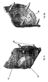
- Figs. 1 and 2 show a dispenser 10 made according to a preferred embodiment of the invention.
- the dispenser 10 is provided with a housing 12.
- the housing 12 is advantageously sized and shaped to accommodate a tubular roll of film 13.
- the lid portion 21 can pivot around the hinge portion 23 and adopt a "closed" position, best shown in Fig. 3d , where the blade 30 is inserted into a cutting channel 26, which is provided on the outer surface of the housing 12 and defined by the raised elements 46 and 47.
- a gripping surface be provided on the dispenser forming a tensioning means.
- the samples tested were of the following materials:
Abstract
Description
- The invention relates to a dispenser for dispensing portions of film or sheets of material such as cellophane or cling film, foil, grease proof paper, wrapping paper etc.
- Films and other sheet materials are usually manufactured as continuous rolls of material and conveniently may be sold in a suitable dispensing device. Films intended for food purposes, such as plastic cling film, microwave film or freezer film, cellophane, metal (e.g. aluminium) foils or greaseproof paper, are generally available in the form of a continuous roll and short sections of an appropriate length are cut off as required. Films for food purposes are commonly sold packaged within a disposable cardboard box which has been adapted to dispense the film during the lifetime of the roll. Thus the box may be provided with a slot through which the film is fed and toothed blades of metal or plastic or card are positioned adjacent to or along one edge of the slot to allow the desired length of film to be torn off.
- However, these boxes are not convenient to use. First, the toothed blades provided are always exposed at the edge of the box. The blades must naturally be sharp enough to tear the film being dispensed and inevitably any user may be cut by the blade whilst removing the portion of film required or in general handling of the box of film. In addition to the painful nature of such a cut, there is a more important hygiene problem which can arise. Thus the cardboard box, if smeared with blood from a cut finger or by traces of foodstuffs etc, cannot easily be wiped clean and since a large roll of catering film may last for several months there is a risk of contamination not only to the film itself, but also to the people who subsequently handle the box and to the food prepared by them after they have handled the box. Second, the rectangular base of cardboard dispensing boxes is easily soaked with water or other fluids. Since the boxes are only formed from cardboard, they become soft permitting moisture to come into contact with the film. If the boxes become very wet, they may even completely collapse which makes any further dispensing of film difficult.
- Another disadvantage of the typical cardboard boxes available is that the film is usually difficult to grab, and when grabbed, it is difficult to separate the desired length of material from the roll without tearing the sheet. Furthermore, it is quite usual that whilst being cut, the end of the sheet thus formed folds over and sticks to itself. When the film is thin and formed from a tacky material (such as cling film) this is highly undesirable as the folded film is rendered unusable for sealing and wrapping purposes and unfolding the folded sheet is extremely difficult.
- The size of these conventional dispensing boxes will of course vary depending on the size of the roll contained therein. Roll size is in turn determined by the frequency of use of the film and the cost per metre of film acceptable to the buyer, and thus there is a distinct variation between the products sold for household use and those of the catering industry. Although the problems arising from such dispensing boxes are more acute in the catering industry (because of the greater frequency of use and increased likelihood of contamination problems), similar inconveniences occur at domestic level.
- Various known dispensers are shown un the following documents:
US4417495 (Gordon et al. ),US4196647 (Fish ),EP0508021 (Huang et al. ),US4458570 (Morrison ), andUS 6105481 (Schuler ). - It is therefore one of the objects of the invention to provide a film dispenser which overcomes at least some of the drawbacks noted above. It is a further object of the invention to provide a dispenser which is disposable, safe and easy to use while being of low cost to manufacture.
- It should be understood that the term "film" encompasses all material provided in thin sheet form, especially kitchen cling film, greaseproof paper, aluminium foil and wrapping paper.
- According to the present invention there is provided a film dispenser comprising a housing adapted to receive and hold a roll of film and having a dispensing opening through which a layer of film may pass, the dispenser being provided with a movable cutting unit having a blade mounted therein, the dispenser further comprising a cutting channel shaped and positioned to receive said blade, /the dispenser further comprising film tensioning means to maintain the tension in a layer of film positioned over the cutting channel. wherein the film tensioning means comprises a gripping surface located on one side of the cutting channel; characterised in that the gripping surface has a shear force in relation to PVC cling film of greater than 100 Nm-1
- Preferably the cutting channel is defined by elongated elements, like flanges, projecting from the surface of the housing, which lie substantially parallel to the dispensing opening.
- By putting the portion of film provided over the cutting channel under tension a neat cut is achieved.
- A gripping surface is predominantly relevant for a cling film dispenser for two main reasons:
- Cling film tends to stick to a variety of surfaces, whereas foil or parchment, for example, do not.
- Cling film is generally more elastic and trickier to cut cleanly than other films and therefore benefits most from being under tension.
- For a gripping surface to be effective it is essential that it grips the film to some degree.
- Defining standard criteria for a suitable surface has not proved possible. Rather, suitable surfaces must be selected by virtue of their ability to sufficiently grip the film of interest. Suitable materials for use as a gripping surface are described later. In addition a test is described which allows the selection of materials which are suitable for use in a gripping surface.
- Preferably the film tensioning means comprises a pair of gripping surfaces, one on each side of the cutting channel. It is particularly preferred that the superior surface of the elongated elements provide the gripping surfaces.
- The gripping surface is advantageously formed of a soft flexible PVC. Particularly preferred is modified nytril rubber PVC. A particularly suitable material is the modified nytril rubber PVC sold by the company API S. p. A of Via D. Alighieri, 27-36065, Mussolente, Italy under the Trade Mark Apilon 33.
- Preferably the movable cutting unit comprises a blade holding channel, the blade holding channel being defined by longitudinal flanges with the blade mounted therebetween.
- Preferably the interior sides of the longitudinal flanges are adapted to co-operate with the exterior surfaces of the elongated elements. This co- operation can take the form of a simple guiding interaction which helps align the film on the gripping surface for efficient cutting; in this interaction there is no real need for physical contact between the longitudinal flanges and the elongated members. Alternatively it can take the form of a physical interaction where the flanges contact the elongated elements trapping the film therebetween.
- Preferably the movable cutting unit is provided on a lid portion which is connected via a hinge to the dispenser, the axis of the hinge lying substantially parallel to the cutting channel.
- Preferably the dispenser is further provided with film presentation means. The presence of a film presenting means is advantageous for two reasons: It may act to prevent the end of the roll of film from getting reattached to the roll, whereby it is difficult to retrieve.
- It presents the film so that it can easily be grasped by the user.
- Preferably the film presentation means comprises a member located between the cutting channel and the dispensing opening, the member being deflectable from a film presenting position, where it stands proud from the dispenser and the roll of film, to a retracted position where it lies substantially within the housing.
- It is further preferred that the housing and the film presenting means are each made from one piece of plastics material. Suitably the housing and the film presenting means are extruded. Extrusion is preferred due to cost effectiveness, simplicity and scalability of the process.
- It is further preferred that the blade is metal saw-toothed blade. A metal blade is preferred as it is generally sharper than a plastics blade. A plastics blade would also be suitable in some instances.
- According to a further embodiment of the present invention there is provided a method of severing a piece of film from a layer of film in a dispenser of the type referred to above comprising the steps of;
- providing a layer of film over the cutting channel;
- providing the film with tensioning means to maintain the tension in the layer of film over the cutting channel; and
- severing said layer of film with the blade.
- Preferably said tensioning means comprise a pair of gripping surface positioned one on each side of the cutting channel.
- The film dispenser of the present invention is of course particularly suited for the dispensing of film for food purposes (especially in the catering industry), but may of course also be used where any roll of film or other sheet material needs to be dispensed in short sections. Examples where the dispenser of the present invention may be especially suitable include hospitals (for the dispension of film or other dressing materials, paper or the like) and schools (for the dispension of wrapping paper).
- The invention will be further described by reference to particularly preferred embodiments of the invention described in the accompanying drawings.
-
-
Fig. 1 is a rear isometric view of a dispenser according to an embodiment of the invention with the lid in an opened position. -
Fig. 2 is a front isometric view of the dispenser with the lid in an opened position. -
Figs. 3a to 3d all show a cross-sectional view of the dispenser from a plane perpendicular to the axis of the roll of film.Fig. 3a shows the lid in an open position.Fig. 3b shows the dispenser with the lid in a partially closed position with the blade contacting the layer of film.Fig. 3c shows the dispenser with the lid slightly more closed and the blade exerting pressure against the layer of film.Fig. 3d shows the lid in a fully closed position with the layer of film severed by the blade. -
Fig. 4 is a side view the dispenser without end caps or blade and no roll of film present. -
Figs. 5a and 5b are isometric views of an end cap from the external and internal sides respectively. -
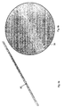
Fig. 6a shows the blade used in the dispenser andFig. 6b shows an enlarged view of the blade. -
Fig. 7 is a sequence of schematic representations of a test apparatus for determining the shear force of a test sample, and illustrating the steps involved in carrying out the test. - Referring to the accompanying drawings,
Figs. 1 and 2 show adispenser 10 made according to a preferred embodiment of the invention. Thedispenser 10 is provided with ahousing 12. Thehousing 12 is advantageously sized and shaped to accommodate a tubular roll offilm 13. - The
housing 12 is of generally square cross-section, but it should be understood that a different shape of housing, for example a housing having a circular or oval cross-section, could also be used. Dispensers designed to contain retail-size film rolls are smaller than the ones designed for the catering industry. For those dispensers a rectangular or square cross-section is preferred as being more convenient to apply labels or the like on the dispenser sides. - As best shown in
Fig. 4 the housing 12 (including the lid portion 21) in this embodiment is a one-piece unit. The film presentation means 16 is made separately and attached to the housing by way of an interlocking notch and grove mechanism. Thehousing 12 andlid portion 21, and the film presentation means 16 are preferably made out of plastics material, for example PVC or other similar plastics material which is safe for food contact. These components can be moulded, or preferably extruded, into the desired shape. The simplicity of manufacture of such components substantially reduces the costs of manufacture of thedispenser 10 as the number of distinct parts is reduced to a minimum, and both the material and the manufacturing process are inexpensive. - The
housing 12 comprises alid portion 21 which is pivotally connected to the remaining part of thehousing 12 via ahinge portion 23. This hingedportion 23 can be made of flexible PVC (e.g. the family of modified nytril rubber PVC compounds known as Apilon 33) which can be co-extruded with the more rigid PVC which forms the major part of thehousing 12. - As shown on
Fig. 2 , alongitudinal blade 30 is mounted on thelid portion 21 as part of a movable cutting unit. Theblade 30 comprises a series of generallytriangular teeth 39 in a saw-tooth arrangement, which are best shown inFigs. 6a and 6b . Theblade 30 is made of metal, preferably stainless steel. However, plastics materials could also be used, though plastic blades are generally less sharp. The tip of thetriangular teeth 39 are tapered to ensure that the material is fully severed after the initial perforation is made. Theblade 30 is sized and shaped to fit within a correspondinglongitudinal slot 22 provided in the movable cutting unit provided on thelid portion 21. The blade is secured within thelongitudinal slot 22 by means of the interlocking of small protuberances in the walls of theslot 22 with notches in theblade 30. - When in the open position, the
lid portion 21, and theblade 30 attached thereto, are at an angle to the top part of the housing 20 to which thelid portion 21 is hinged and thus defines a dispensingopening 50 shown inFigs. 1 and3 . The dispensingopening 50 is wide enough so that at least one layer of thefilm 14 to be dispensed can be passed through, and is long enough so that the full width offilm 14 can also be passed through without wrinkling or folding. - The
lid portion 21 can pivot around thehinge portion 23 and adopt a "closed" position, best shown inFig. 3d , where theblade 30 is inserted into a cuttingchannel 26, which is provided on the outer surface of thehousing 12 and defined by the raisedelements -
Dispenser 10 is provided with tensioning means which act to ensure the portion offilm 14 over the cuttingchannel 26 is held under tension as it is cut. - In this embodiment of the invention the tensioning means comprises
film gripping surfaces Fig. 4 , grippingsurfaces groove 26. The film is thus held by the grippingsurfaces elongated elements channel 26, and this arrangement has proven to be particularly efficient. The gripping surfaces 32,33 are advantageously provided along the entire length of the edge of the cuttingchannel 26. - The tensioning means of the
dispenser 10 may also comprise further elements besides the grippingsurfaces elongated elements longitudinal flanges surface elongated elements longitudinal flanges longitudinal flanges elongated elements gripping elements longitudinal flanges - In an alternative embodiment the internal side of the
longitudinal flanges elongated elements longitudinal flanges elongated elements film 14 which passes over the cuttingchannel 26 will be trapped between thelongitudinal flanges elongated elements lid portion 21 is closed and thus held tightly. Contact between the longitudinal flanges and the elongated elements is not, however, essential for the operation of the dispenser. - Thus the longitudinal flanges and elongated elements, in co-operation with the gripping
surfaces channel 26 during cutting. - In addition, these features cause the severed portion of
film 14 to remain positioned along the edge of the cuttingchannel 26 after cutting, and before the user removes the severed sheet from thedispenser 10 thus avoiding inadvertent folding or wrinkling and the like of the severed sheet. - In use the tensioning means of the present dispenser operate as follows:
- A length of
film 14 is pulled by the user over the cuttingchannel 26 and placed in contact with the grippingsurfaces Figs. 3a to 3d , when thelid portion 21 is moved to the closed position by the user, thelongitudinal flanges channel 26 and drag it along the external faces of theelongated elements surface - The dispenser also has a film presentation means which is located between the cutting
channel 26 and the dispensingopening 50. It advantageously comprises amember 16 in the form of a Y-shaped piece of resilient plastics material. It is attached to thehousing 12 at along the edge of the dispensing opening by the base of the Y. Particularly when cling film is used it is often difficult to separate the end of the roll offilm 13 from the bulk of the roll. To prevent this problem, the film presentation means 16 is provided in order to retain the edge of thefilm 14 connected to theroll 13 separate from the roll and rendering it easily grippable. - The
member 16 is resilient and can flex from a film presenting position to a recessed position (as shown inFigs. 3a to 3d ). When thelid 21 is closed it deflects themember 16 from the film presenting to the recessed position. When thelid 21 is re-opened, themember 16 springs back to the film presenting position. As themember 16 springs back to the film presenting position it lifts the end of thefilm 14 from the cuttingchannel 26 and holds it in a position in which it is easily accessible for the user to grasp. The resilient nature of themember 16 also makes it possible to flex it out of the way if access to the roll offilm 13 is required, for example if the end of the film requires retrieval. - The operation of the dispenser to obtain a severed sheet of film will now be described:
-
Fig. 3a shows thelid portion 21, provided with theblade 30 at its extremity, which lies in its normally opened position. When the user pulls the desired length offilm 14, a portion of the film lies over the cuttingchannel 26. The user then applies pressure on the external surface of thelid portion 21, moving thelid portion 21 and consequently the movable cutting unit towards the cuttingchannel 26.Fig. 3b shows that, as the movement of theblade 30 toward the cuttingchannel 26 continues, thelongitudinal flanges elongated elements film 14 to be cut is held in position and as theblade 30 contacts thefilm 14. Continued downward movement of thelid portion 21 engages theblade 30 with thefilm 14, which is now held under tension. As the pressure on the film increases the tips of the blade pierce the layer of film 14 (Fig. 3c ). As the movement is continued theblade 30 continues cut until the layer of film is completely severed as shown inFig. 3d . The cut edges of thefilm 14 are retained in position until thelid portion 21 is raised. Thelid portion 21 can then be returned to its normal (opened) position and the sheet offilm 14 which has been severed is freed and available for immediate use. - It is particularly advantageous that when the
lid portion 21 is opened, the edge of the separated sheet of film will be held in position by the grippingsurface 33. The other severed end initially remains attached to gripingsurface 32, but it is lifted clear by the film presentation means. Themember 16 of the film presentation means holds the film proud from the rest of thedispenser 10 enabling the user to easily grasp the film for repeat use. -
Figs. 5a and 5b shows twoend caps 60 which are provided at the two lateral extremities of thehousing 12. These end caps 60 can be attached to thehousing 12 throughprongs 62 which engage socket connection points 69 provided within the housing 20. Advantageously theprongs 62 will break if the end caps 60 are removed so as to prevent re-use of thedispenser 10. Asmall area 61 of the end caps 60 can be thinned down so as to be transparent or translucent to allow the user to see the amount of film remaining on the roll offilm 13. Also, the interior profile of thecap 64 advantageously guides the core of the roll offilm 13 into its normal centre of rotation in order to facilitate easy assembly of the dispenser and render it suitable for mass production. - When the end caps 60 are provided on the housing 20 the
dispenser 10 thus formed is substantially water-tight and sealed from external contaminants. Thus, when thedispenser 10 is positioned on a kitchen working surface (which are frequently wet) theroll 13 will be less susceptible to being soaked and/or accidentally contaminated. - An optional feature (not shown in the drawings) is the incorporation of an additional hinged section to allow easier access to the roll of
film 13. In operation it may be difficult to retrieve the end of thefilm 14 from the roll offilm 13. For this reason an additional hinge may be provided between thehinge 23 oflid portion 21 and the remaining part of the dispenser housing 20. This hinged top section would usually be held closed through a longitudinal catch on the housing 20, coaxial with thehinge 23, the catch engaging with corresponding small prongs provided on theend cap 60. If wider access to the roll of film 13 (for example if the end of thefilm 14 has fallen inside thehousing 12 and is difficult to grab) this catch can be detached from the prongs and the additional part of the housing can be opened. Once the end of the film has been retrieved the section can then be reclosed. In this position, access to the roll offilm 12 would be restricted, thus reducing the risk of contamination. - Alternatively the
lid portion 21 can simply be made wide enough allow easy access to the roll offilm 13. This alternative is preferred when thedispenser 10 is sized to receive small rolls of film and is intended for domestic use. - As mentioned previously, the dispenser is suitable for dispensing a number of different materials including films, foils and parchments. The exact specifications of the dispenser for different materials will likely alter, but the general principles will remain the same. In a dispenser for aluminium foil, for example it is found that efficient cutting is achieved without gripping
surfaces longitudinal flanges elongated elements - When cling film is used, it is highly desirable that a gripping surface be provided on the dispenser forming a tensioning means.
- The presence of a gripping surface at the edge of the cutting channel is particularly advantageous in this invention. The choice of the material to apply on the cutting channel is determined by the nature of the film to be cut.
- Generally a suitable material for gripping cling film or the like must have suitable material surface properties. It is believed that such surfaces facilitate the formation of a "vacuum effect" by virtue of the exclusion of air from between the film and the surface. This vacuum effect then resists movement or removal of the film. The chemical nature of the surface may also play an important role.
- It is proposed that the suitability of a material as a gripping surface is determined by three main factors:
- 1) The chemical composition of the film and the gripping surface.
In particular, the degree of cross-linked polymers in each may have an effect on how well the surfaces will adhere. - 2) The roughness of the gripping surface.
Cling film adheres less readily to a rough surface as there are more air pockets between the film and the surface and there is therefore less chance of forming a vacuum or of chemical adherence between the materials. The surface finish of a material is determined mainly by the manufacturing process although certain materials may never be suitable due to porosity or other inability to form a smooth surface. - 3) The flexibility of the material forming the gripping surface. On a microscopic level a more flexible material smoothes out more easily and hence promotes the chemical or vacuum effects that adhere the surfaces together.
- As there are numerous chemical and mechanical effects involved in the adherence of cling film to a surface, it is extremely difficult to accurately assess from the properties of a material alone whether or not it will grip a certain type of film. This makes selection of materials for the gripping surface difficult.
- In order to select a suitable material for the gripping surface a simple trial and error process can be adopted. A number of suitable surfaces could be tried until a suitable material is found. The number of materials tested could be limited by the knowledge that the material should be capable of forming a non-porous surface.
- However it would be expensive and time consuming to manufacture a sample dispenser from all proposed materials and it is therefore beneficial if a simple test can be performed to assess the suitability of a material. To this end a suitable test apparatus is described below.
- A measurement that can be taken to compare the adherent properties of cling film against a gripping surface is the "shear force" required to free the film from the gripping surface. The shear force is clearly dependent on all three factors mentioned earlier. It must be noted, however, that to allow comparison between gripping surfaces exhibiting differing sizes, this shear force must be quantified relative to the length of the test sample over which the film is adhered.
- The shear force of a test sample of a material can be obtained using the test described below. Preferably the area and the dimensions of the different test samples to which the cling film grips should be constant. Generally a larger area of test sample will be used than would actually be found in the gripping surface of the dispenser. The larger surface area helps to minimise the level of error in the results of the test. It is, however, useful if the geometry of the surface of the test sample is similar to the geometry of the gripping surface of the dispenser.
- It will be understood that for a material to be suitable for the gripping surface the shear force has to be of sufficient magnitude to ensure that the pressure of the blade against the film causes the film to yield and sever, i.e. the film does not slip as it is cut. The exact arrangement of blade type, gripping material properties, geometry etc is not important so long as the shear pressure of the material is sufficient to facilitate severing.
- It is not possible to define a precise threshold limit of shear force below which a material will not be suitable, and above which it will; there are simply too many variables involved. These variables include:
- Geometry of the gripping surface,
- other tensioning means in the dispenser, e.g. jaw arrangement, and
- type of film to be severed.
- However, it will be possible to assess whether a material can be dismissed immediately as not suitable, has potential, or is a definite candidate for use as a gripping surface.
- By using the methodology described below, the shear force of virtually any material can be determined to investigate whether it is suitable for use as a gripping surface.
- In summary, the shear force is obtained by adhering a layer of film over a sample of the material to be tested. Then a force is applied to the film. The force is steadily increased until the film is detached from the sample. The force recorded before the film is detached from the sample is the shear force. This value is divided by the length of the test sample to obtain the shear force relative per unit length.
-
Fig. 7 shows a suitable test apparatus. The test sample is preferably shaped as acylindrical rod 70 and is mounted on a hingedtest platform 72. The hingedtest platform 72 provides a clamping means (not shown) for maintaining thetest rod 70 in a position whereby it cannot move through either rotational or cartesian translations. Clearly there are a number of suitable clamping means available in the art, for example a fixed collar which can be tightened to hold therod 70 securely. The hingedtest platform 72 is able to rotate about ahinge 76. The hingedtest platform 72 also has abottle 74 fixed thereto at the end distal to the hinge. It is important to note that the forces on the hingedtest platform 72 are balanced when thebottle 74 is empty; thus the hinged test platform works like a balance and only when thebottle 74 is filled is a torque applied to thehinge 76 and movement occurs. - The test apparatus further comprises a
film holding platform 80. Thefilm holding platform 80 has afilm clamp 82 which is designed to hold the test sample of film tightly and prevent slipping. Thefilm clamp 82 may comprise two bars of steel having flat parallel faces which, when clamping the film, are urged firmly together sandwiching the film therebetween. For example the two bars may be bolted together or clamped using a G-clamp. The film clamp is securely attached to the film holding platform. - A reserve or dispenser of
film 78 may also be provided for in the test apparatus, conveniently located on thefilm holding platform 80. This is not essential and is not immediately involved in the operation of the test apparatus and is merely provided for convenience. - A
film press 84 is used to adhere the film onto the test sample. As shown inFigure 7 , it is advantageously a block containing a profile complimentary to that of the top surface of the test sample. Thefilm press 84 is of known weight and engages thetest rod 70 through a vertical motion. It applies a known force (weight) and thus pressure onto thefilm 74 draped over thetest rod 70. The known force is supplied by the weight of thefilm press 84 or, if insufficient, known weights can be added on top of thefilm press 82. This adheres thefilm 86 to the surface of thetest rod 70 in a way approximately analogous to the pressure applied to the film as the dispenser closes. It is thought that the amount of pressure imparted by thefilm press 82 is not critical to the results of the test so long as it is sufficient to press thefilm 86 into close contact with thetest rod 70. Once adherence has been achieved, applying a greater pressure would not significantly increase the level of adhesion. - A sample is tested according to the following method, described with reference to
Figure 7 : A sample offilm 86 is drawn from thedispenser 78 and passed between the two bars of thefilm clamp 82. The bars are clamped together to hold the film tightly across its entire width. The film is draped over thetest rod 70 with as little slack as possible and thefilm press 84 brought into contact with the film. - Once the sample of film has been clamped by the
film clamp 82, and adherence of thefilm 86 to thetest rod 70 has been achieved, thebottle 74 is gradually filled with water. The slower and more constant the water is added the better as this allows a more accurate determination of the exact end-point volume of water when slippage occurs, and also surges of water would cause unmeasurable forces not related to the volume of water in the container, thus lessening accuracy. When thefilm 86 slips from thetest rod 70 the water flow is stopped. This can either be achieved manually stopping the flow (eg. shutting a valve), though this method is open to human error. Alternatively slippage could cause the opening of bottle to move away from the water source thus preventing further water from entering the bottle. - The final volume of water in the bottle is measured and the shear force and/or shear pressure calculated. In the present apparatus the shear force is calculated by calculating the torque imparted at the
hinge 76 by thetest platform 72 and from this deriving the force applied at the surface of thetest rod 70. As the hinged test platform were balanced before the addition of the water the torque on thehinge 76 will be dependent on the weight of the water in thebottle 74 and the distance of thebottle 74 from thehinge 76. - A test of this nature was carried out for a number of materials in association with commercially available PVC cling film, and the results are presented in Table 1.
- In the test apparatus as used to obtain these results the critical dimensions were as follows:
- Diameter of Test Rod: 9mm
- Distance from hinge to centre of mass of bottle: 850mm
- Distance from hinge to surface of test rod: 95mm
- The samples tested were of the following materials:
- Apilon 33: a modified nytril rubber PVC
- Atochem FEJ 611: PVC based extrudable thermoplastic polymer.
- C40/55 Grey Dugdale: PVC based extrudable thermoplastic polymer
- Apigo 8348NL: SEBS based extrudable thermoplastic polymer
- Alcryn 2250 UT: PVC based extrudable thermoplastic polymer
- Laporte: SEBS based extrudable thermoplastic polymer
- Glass: tubular glass from fluorescent light tube.
- As can be seen there is a great difference between the shear force values of each of the samples. Glass and
Apilon 33 both exhibit high shear force values. In fact glass exhibits such a high shear force that the layer of film actually failed before it slipped from the test rod. Other samples did not adhere to the film at all well, e.g. Alcryn 2250 UT and C40/55 Grey Dugdale. - To test the validity of this result a test sample of the dispenser was made up with
Apilon 33 and Alcryn 2250 UT as the gripping surfaces. The polymers were co-extruded with the rigid PVC polymer which forms the bulk of the dispenser. As was expected thedispenser containing Apilon 33 severed the film consistently, whereas the dispenser using Alcryn 2250 UT was far less effective, with the cutting process being less consistent and effective with incomplete severing occurring. This demonstrates that the proposed test is a valid means of assessing the suitability of a material for use as the gripping surface. - If a dispenser were required to dispense another type of film, e.g. polyethylene (PE) cling film rather than PVC cling film, the test could be repeated for a number of different test materials to select suitable candidates for incorporation into the dispenser. Indeed the same test was carried out using polyethylene film and a number of test materials and Laporte™ (a styrene-ethylene-butadiene-styrene thermoplastic elastomer) was found to be suitable for use as a gripping surface for polyethylene cling film. This is significant as it is likely that PE will largely replace PVC as the material of choice for cling film production (due to improved safety of PE).
- Some general factors have been identified which can be used to speculate on the desired properties of a material for use as a gripping surface. These include:
- Slightly pliable or flexible materials have been found to work better than rigid materials. A hardness rating of 40 - 60 Shore A has been found to be generally suitable.
- The surface should be non-porous, though a glossy finish is not required.
- PVC cling film tends to adhere to PVC based materials well, it may be speculated that the same would apply to PE or other film materials.
- It will be noted that, no matter how well a material grips the film of interest, it will not be suitable for use as a gripping surface if it cannot be incorporated into the dispenser. This might happen for example if the material will not coextrude with the material which makes up the bulk of the dispenser.
- It is also important that the conditions used in the manufacture of the test sample generally reflect the conditions that will be used in the dispenser. This is because the processing of the material can alter its shear force. In general, however, the alteration is not very significant.
| Test | Material | Aplion | 33 Vol (ml) | Atochem FEJ. 611 Vol (ml) | C40/55 Grey Dugdale Vol (ml) | Apigo 8348 NL Vol (ml) | Alcryn 2250 UT Vol (ml) | Laporte Vol (ml) | Glass Vol (ml) |
| 1 | 415.00 | 130.00 | 0.00 | 115.00 | 20.00 | 130.00 | 635.00 | ||
| 2 | 460.00 | 130.00 | 0.00 | 135.00 | 0.00 | 125.00 | 635.00 | ||
| 3 | 445.00 | 130.00 | 0.00 | 275.00 | 0.00 | 152.00 | 635.00 | ||
| 4 | 440.00 | 150.00 | 0.00 | 140.00 | 0.00 | 250.00 | 635.00 | ||
| 5 | 520.00 | 140.00 | 0.00 | 175.00 | 0.00 | 160.00 | 635.00 | ||
| 6 | 465.00 | 120.00 | 0.00 | 225.00 | 0.00 | 240.00 | 635.00 | ||
| 7 | 390.00 | 160.00 | 0.00 | 195.00 | 0.00 | 315.00 | 635.00 | ||
| 8 | 575.00 | 135.00 | 0.00 | 155.00 | 0.00 | 340.00 | 635.00 | ||
| 9 | 460.00 | 100.00 | 0.00 | 185.00 | 0.00 | 350.00 | 635.00 | ||
| 10 | 575.00 | 122.00 | 0.00 | 215.00 | 10.00 | 400.00 | 635.00 | ||
| Average | 474.50 | 131.70 | 0.00 | 181.50 | 3.00 | 246.20 | 635.00 | ||
| Medium | 460.00 | 130.00 | 0.00 | 180.00 | 0.00 | 245.00 | 635.00 | ||
| SD | 62.82 | 16.53 | 0.00 | 48.31 | 6.75 | 101.38 | 0.00 |
| Force Calculations | ||||||||
| Mass Ave (Kg) | 0.47 | 0.13 | 0.00 | 0.18 | 0.00 | 0.25 | 0.64 | |
| Mass Med (Kg) | 0.46 | 0.13 | 0.00 | 0.18 | 0.00 | 0.25 | 0.64 | |
| Weight Ave (N) | 4.65 | 1.29 | 0.00 | 1.78 | 0.03 | 2.42 | 6.23 | |
| Weight Med (N) | 4.51 | 1.28 | 0.00 | 1.77 | 0.00 | 2.40 | 6.23 | |
| SD (Kg) | 0.06 | 0.02 | 0.00 | 0.05 | 0.01 | 0.10 | 0.00 | |
| SD (N) | 0.62 | 0.16 | 0.00 | 0.47 | 0.07 | 0.99 | 0.00 |
| Torque at Pivot | ||||||||
| Torque at Pivot AVE. (Nm) | 3.96 | 1.10 | 0.00 | 1.51 | 0.03 | 2.05 | 5.29 | |
| Torque at Pivot MED (Nm) | 3.84 | 1.08 | 0.00 | 1.50 | 0.00 | 2.04 | 5.29 | |
| Torque at Pivot SD (Nm) | 0.52 | 0.14 | 0.00 | 0.40 | 0.06 | 0.85 | 0.00 |
| Shear Release Force | ||||||||
| Force at Shear AVE. (N) | 41.65 | 11.56 | 0.00 | 15.93 | 0.26 | 21.61 | 55.74 | |
| Force at Shear MED (N) | 40.38 | 11.41 | 0.00 | 15.80 | 0.00 | 21.50 | 55.74 | |
| Force at Shear SD (N) | 5.51 | 1.45 | 0.00 | 4.24 | 0.59 | 8.90 | 0.00 |
| Shear Release Force per Metre | ||||||||
| Force at Shear AVE. (N/m) | 138.83 | 38.53 | 0.00 | 53.10 | 0.88 | 72.03 | 185.79 | |
| Force at Shear med (N/m) | 134.59 | 38.04 | 0.00 | 52.66 | 0.00 | 71.68 | 185.79 | |
| Force at Shear SD. (N/m) | 18.38 | 4.84 | 0.00 | 14.13 | 1.97 | 29.66 | 0.00 |
| Summary | ||||||||
| Force at Shear MED. (N/ m) | 134.59 | 38.04 | 0.00 | 52.66 | 0.00 | 71.68 | 185.79 | |
| +/- | 30.15 | 7.93 | 0.00 | 23.18 | 3.24 | 48.65 | 0.00 | |
| 95th%ile. Max. | 164.73 | 45.97 | 0.00 | 75.84 | 3.24 | 120.33 | 185.79 | |
| 5th%ile. Min. | 104.44 | 30.10 | 0.00 | 29.48 | 0.00 | 23.03 | 185.79 |
Claims (15)
- A film dispenser (10) comprising a housing (12) adapted to receive and hold a roll of film (13) and having a dispensing opening (50) through which a layer of film may pass, the dispenser being provided with a movable cutting unit having a blade (30) mounted therein, the dispenser further comprising a cutting channel (26) shaped and positioned to receive said blade, the dispenser further comprising film tensioning means to maintain the tension in a layer of film positioned over the cutting channel, wherein the film tensioning means comprises a gripping surface (32, 33) located on one side of the cutting channel; characterised in that the gripping surface has a shear force in relation to PVC cling film of greater than 100 Nm-1.
- A dispenser as claimed in claim 1 wherein the cutting channel is defined by elongated elements (46, 47) projecting from the surface of the housing, which lie substantially parallel to the dispensing opening.
- A dispenser as claimed in claim 1 wherein the film tensioning means comprises a pair of gripping surfaces (32, 33), one on each side of the cutting channel.
- A dispenser as claimed in any preceding claim wherein the superior surface of the elongated elements provide the gripping surfaces.
- A dispenser as claimed in any preceding claim, wherein each gripping surface is formed from a modified nytril rubber PVC.
- A dispenser as claimed in any one of claims 1 to 5 wherein the movable cutting unit comprises a blade holding channel (22), the blade holding channel being defined by longitudinal flanges with the blade mounted therebetween.
- A dispenser as claimed in claim 6 wherein the interior sides of the longitudinal flanges are adapted to co-operate with the exterior surfaces of the elongated elements.
- A dispenser as claimed in any one of claims 1 to 7 wherein the movable cutting unit is provided on a lid portion (21) which is connected via a hinge (23) to the dispenser, the axis of the hinge lying substantially parallel to the cutting channel.
- A dispenser as claimed in any one of claims 1 to 8 wherein the dispenser is further provided with film presentation means (16).
- A dispenser as claimed in claim 9 wherein the film presentation means comprises a member located between the cutting channel and the dispensing opening, said member being deflectable from a film presenting position, where it stands proud from the dispenser and the roll of film, to a retracted position where it lies substantially within the housing.
- A dispenser as claimed in any one of claims 1 to 10 wherein the housing and the film presenting means are each made from one piece of plastics material.
- A dispenser as claimed in claim 11 wherein the housing and the film presenting means are extruded.
- A dispenser as claimed in any one of claims 1 to 12 wherein the blade (30) is metal saw-toothed blade.
- A method of severing a piece of film from a layer of film in a dispenser (10) of the type claimed in any preceding claim, comprising the steps of;- providing a layer of film (14) over the cutting channel (26);- tensioning the film with the tensioning means to maintain the tension in the layer of film over the cutting channel; and- severing said layer of film with the blade (30).
- The method of claim 14 wherein said tensioning means comprise a pair of gripping surfaces (32, 33) positioned one on each side of the cutting channel.
Applications Claiming Priority (3)
| Application Number | Priority Date | Filing Date | Title |
|---|---|---|---|
| GBGB0211956.8A GB0211956D0 (en) | 2002-05-24 | 2002-05-24 | Dispenser |
| GB0211956 | 2002-05-24 | ||
| PCT/GB2003/002299 WO2003099693A1 (en) | 2002-05-24 | 2003-05-27 | Roller sheet material dispenser |
Publications (2)
| Publication Number | Publication Date |
|---|---|
| EP1507729A1 EP1507729A1 (en) | 2005-02-23 |
| EP1507729B1 true EP1507729B1 (en) | 2012-06-06 |
Family
ID=9937326
Family Applications (1)
| Application Number | Title | Priority Date | Filing Date |
|---|---|---|---|
| EP03755233A Expired - Lifetime EP1507729B1 (en) | 2002-05-24 | 2003-05-27 | Roller sheet material dispenser |
Country Status (10)
| Country | Link |
|---|---|
| US (2) | US20050166730A1 (en) |
| EP (1) | EP1507729B1 (en) |
| JP (1) | JP2005526630A (en) |
| CN (1) | CN1656002A (en) |
| AU (2) | AU2003251122A1 (en) |
| CA (1) | CA2483629A1 (en) |
| GB (1) | GB0211956D0 (en) |
| NO (1) | NO20044929L (en) |
| WO (1) | WO2003099693A1 (en) |
| ZA (1) | ZA200408718B (en) |
Cited By (1)
| Publication number | Priority date | Publication date | Assignee | Title |
|---|---|---|---|---|
| DE202018106007U1 (en) | 2018-10-19 | 2018-10-31 | Leifheit Ag | foil dispenser |
Families Citing this family (17)
| Publication number | Priority date | Publication date | Assignee | Title |
|---|---|---|---|---|
| GB0211956D0 (en) * | 2002-05-24 | 2002-07-03 | Benedetti Internat Plc | Dispenser |
| US20050205637A1 (en) * | 2003-04-28 | 2005-09-22 | Life Two Co., Ltd. | Cling wrap case |
| WO2006037944A1 (en) * | 2004-10-01 | 2006-04-13 | Avanti Blue Ltd | Dispenser for rolls of sheet material with closure mechanism |
| FR2895985A1 (en) * | 2006-01-12 | 2007-07-13 | Sphere Sa | Domestic packaging film e.g. aluminum film, distributing reel, has rail extending in cutting zone, and slide sliding in rail, where slide comprises blades to cut film`s end portion held in cutting zone, during displacement of slide |
| DE102006037432C5 (en) * | 2006-08-09 | 2014-08-14 | Leonhard Kurz Gmbh & Co. Kg | Method for producing at least one window opening in an elongate paper substrate, and device |
| US20100288094A1 (en) * | 2007-07-03 | 2010-11-18 | David Pynt | Cutting Assembly |
| WO2009148433A1 (en) * | 2008-06-01 | 2009-12-10 | Bouncing Brain Innovations Season Three Subsidiary 6, Llc | Pliable sheet dispensers |
| DE202008015031U1 (en) * | 2008-11-13 | 2010-04-22 | Emsa Gmbh | Handabrollvorrichtung |
| JP5709459B2 (en) * | 2009-10-22 | 2015-04-30 | 旭化成ケミカルズ株式会社 | Film case |
| GB201008480D0 (en) * | 2010-05-21 | 2010-07-07 | Wrap Film Systems Ltd | Polyethylene film dispenser |
| GB2485245B (en) | 2011-03-14 | 2012-10-17 | Wrap Film Systems Ltd | An anti misuse system |
| US9630797B2 (en) * | 2014-12-12 | 2017-04-25 | The Glad Products Company | Dispenser for material |
| CN104552218B (en) * | 2015-01-19 | 2017-04-19 | 国家电网公司 | Lofting tool and method of electrical device base |
| ES2885848T3 (en) * | 2015-12-11 | 2021-12-15 | Sedat Tahir Tuketim Maddeleri San A S | Film cutting and storage box |
| US11401125B2 (en) | 2017-07-22 | 2022-08-02 | Source Unlimited Llc | Wrapping material roll tensioner system, method of manufacture and use |
| US10717620B2 (en) | 2017-07-22 | 2020-07-21 | Source Unlimited Llc | Wrapping material roll tensioner |
| JP6383991B1 (en) * | 2018-02-06 | 2018-09-05 | ファ・シャープメディックデザイン株式会社 | Medical wrap film set and manufacturing method thereof |
Family Cites Families (12)
| Publication number | Priority date | Publication date | Assignee | Title |
|---|---|---|---|---|
| US4196647A (en) | 1978-08-15 | 1980-04-08 | Reynolds Metals Company | Carton for dispensing and cutting sheet material |
| US4458570A (en) * | 1982-01-25 | 1984-07-10 | Marvin Glass & Associates | Sheet material dispenser |
| US4417495A (en) * | 1982-02-12 | 1983-11-29 | Rgg, Inc. | Web dispenser |
| US5107732A (en) * | 1986-09-12 | 1992-04-28 | Hanmer Peter B | Severing apparatus |
| US5146828A (en) | 1991-03-29 | 1992-09-15 | Huang Hong Yuan | Wrap film cutter |
| US5280741A (en) * | 1993-01-19 | 1994-01-25 | Belport Company, Inc. | Thread dispenser with cutter |
| US5440961A (en) * | 1994-01-24 | 1995-08-15 | Reynolds Metals Company | Film cutting apparatus and method |
| US6105481A (en) * | 1995-05-15 | 2000-08-22 | Schuler; Pius | Foil dispenser |
| US7918151B2 (en) * | 2000-12-20 | 2011-04-05 | Aep Industries, Inc. | Film cutter assembly |
| US20030178462A1 (en) * | 2002-03-19 | 2003-09-25 | Johnson Huang | Film wrapper cutting device |
| GB0211956D0 (en) * | 2002-05-24 | 2002-07-03 | Benedetti Internat Plc | Dispenser |
| US20050205637A1 (en) * | 2003-04-28 | 2005-09-22 | Life Two Co., Ltd. | Cling wrap case |
-
2002
- 2002-05-24 GB GBGB0211956.8A patent/GB0211956D0/en not_active Ceased
-
2003
- 2003-05-27 CA CA002483629A patent/CA2483629A1/en not_active Abandoned
- 2003-05-27 WO PCT/GB2003/002299 patent/WO2003099693A1/en active Application Filing
- 2003-05-27 US US10/513,766 patent/US20050166730A1/en not_active Abandoned
- 2003-05-27 EP EP03755233A patent/EP1507729B1/en not_active Expired - Lifetime
- 2003-05-27 JP JP2004507360A patent/JP2005526630A/en active Pending
- 2003-05-27 CN CN03811890.4A patent/CN1656002A/en active Pending
- 2003-05-27 AU AU2003251122A patent/AU2003251122A1/en not_active Abandoned
-
2004
- 2004-10-27 ZA ZA2004/08718A patent/ZA200408718B/en unknown
- 2004-11-11 NO NO20044929A patent/NO20044929L/en not_active Application Discontinuation
-
2007
- 2007-10-29 US US11/978,303 patent/US20080127791A1/en not_active Abandoned
-
2011
- 2011-02-14 AU AU2011200613A patent/AU2011200613B2/en not_active Expired
Cited By (1)
| Publication number | Priority date | Publication date | Assignee | Title |
|---|---|---|---|---|
| DE202018106007U1 (en) | 2018-10-19 | 2018-10-31 | Leifheit Ag | foil dispenser |
Also Published As
| Publication number | Publication date |
|---|---|
| AU2011200613A1 (en) | 2011-03-03 |
| US20080127791A1 (en) | 2008-06-05 |
| WO2003099693A1 (en) | 2003-12-04 |
| NO20044929L (en) | 2004-11-11 |
| GB0211956D0 (en) | 2002-07-03 |
| US20050166730A1 (en) | 2005-08-04 |
| JP2005526630A (en) | 2005-09-08 |
| ZA200408718B (en) | 2005-12-28 |
| AU2011200613B2 (en) | 2012-02-16 |
| CA2483629A1 (en) | 2003-12-04 |
| CN1656002A (en) | 2005-08-17 |
| AU2003251122A1 (en) | 2003-12-12 |
| EP1507729A1 (en) | 2005-02-23 |
Similar Documents
| Publication | Publication Date | Title |
|---|---|---|
| US20080127791A1 (en) | Roller sheet material dispenser | |
| US20030140760A1 (en) | Film cutter | |
| AU2008271925B2 (en) | Cutting assembly | |
| US7424843B2 (en) | Wrapping paper storage device and dispenser | |
| US8714428B2 (en) | Sheet product dispenser | |
| US20040194895A1 (en) | Tape dispenser | |
| CA2143454C (en) | Plastic film food wrap dispenser | |
| US6658742B2 (en) | Bag slitting apparatus with flat cutting blade | |
| US4787543A (en) | Dispenser with cutting device | |
| US20120298709A1 (en) | Film dispenser | |
| GB2170182A (en) | An applicator for self-adhesive sheet material | |
| US5588219A (en) | Rolled sheet material having releasable anti-tack guide strip | |
| GB2116152A (en) | Spout for a liquid container | |
| AU2009202941B2 (en) | Film dispenser | |
| KR20100115471A (en) | Wrap film case | |
| US20100089010A1 (en) | Method and device for plastic wrap | |
| US2936938A (en) | Bag opener or tearing device | |
| GB2546595A (en) | Cling film dispenser | |
| CA2685627A1 (en) | Film dispenser | |
| JPH09227017A (en) | Tape cutter | |
| FR2847559A1 (en) | Plastic dispenser box for a roll of continuous sheet material comprises tongues forming means for locking the roll in place | |
| SK500232011U1 (en) | Unlock end of shrink foil |
Legal Events
| Date | Code | Title | Description |
|---|---|---|---|
| PUAI | Public reference made under article 153(3) epc to a published international application that has entered the european phase |
Free format text: ORIGINAL CODE: 0009012 |
|
| 17P | Request for examination filed |
Effective date: 20041029 |
|
| AK | Designated contracting states |
Kind code of ref document: A1 Designated state(s): AT BE BG CH CY CZ DE DK EE ES FI FR GB GR HU IE IT LI LU MC NL PT RO SE SI SK TR |
|
| AX | Request for extension of the european patent |
Extension state: AL LT LV MK |
|
| DAX | Request for extension of the european patent (deleted) | ||
| REG | Reference to a national code |
Ref country code: HK Ref legal event code: DE Ref document number: 1074430 Country of ref document: HK |
|
| 17Q | First examination report despatched |
Effective date: 20100611 |
|
| GRAP | Despatch of communication of intention to grant a patent |
Free format text: ORIGINAL CODE: EPIDOSNIGR1 |
|
| REG | Reference to a national code |
Ref country code: HK Ref legal event code: WD Ref document number: 1074430 Country of ref document: HK |
|
| RAP1 | Party data changed (applicant data changed or rights of an application transferred) |
Owner name: WRAP FILM SYSTEMS LIMITED |
|
| GRAS | Grant fee paid |
Free format text: ORIGINAL CODE: EPIDOSNIGR3 |
|
| GRAA | (expected) grant |
Free format text: ORIGINAL CODE: 0009210 |
|
| AK | Designated contracting states |
Kind code of ref document: B1 Designated state(s): AT BE BG CH CY CZ DE DK EE ES FI FR GB GR HU IE IT LI LU MC NL PT RO SE SI SK TR |
|
| REG | Reference to a national code |
Ref country code: GB Ref legal event code: FG4D |
|
| REG | Reference to a national code |
Ref country code: DE Ref legal event code: R081 Ref document number: 60341162 Country of ref document: DE Owner name: MELITTA UK LTD., TELFORD, GB Free format text: FORMER OWNER: BENEDETTI INTERNATIONAL PLC, WISHAW, LANARKSHIRE, GB |
|
| REG | Reference to a national code |
Ref country code: AT Ref legal event code: REF Ref document number: 560930 Country of ref document: AT Kind code of ref document: T Effective date: 20120615 Ref country code: CH Ref legal event code: EP |
|
| REG | Reference to a national code |
Ref country code: IE Ref legal event code: FG4D |
|
| REG | Reference to a national code |
Ref country code: DE Ref legal event code: R096 Ref document number: 60341162 Country of ref document: DE Effective date: 20120809 |
|
| REG | Reference to a national code |
Ref country code: NL Ref legal event code: VDEP Effective date: 20120606 |
|
| PG25 | Lapsed in a contracting state [announced via postgrant information from national office to epo] |
Ref country code: FI Free format text: LAPSE BECAUSE OF FAILURE TO SUBMIT A TRANSLATION OF THE DESCRIPTION OR TO PAY THE FEE WITHIN THE PRESCRIBED TIME-LIMIT Effective date: 20120606 Ref country code: SE Free format text: LAPSE BECAUSE OF FAILURE TO SUBMIT A TRANSLATION OF THE DESCRIPTION OR TO PAY THE FEE WITHIN THE PRESCRIBED TIME-LIMIT Effective date: 20120606 Ref country code: CY Free format text: LAPSE BECAUSE OF FAILURE TO SUBMIT A TRANSLATION OF THE DESCRIPTION OR TO PAY THE FEE WITHIN THE PRESCRIBED TIME-LIMIT Effective date: 20120606 |
|
| REG | Reference to a national code |
Ref country code: AT Ref legal event code: MK05 Ref document number: 560930 Country of ref document: AT Kind code of ref document: T Effective date: 20120606 |
|
| PG25 | Lapsed in a contracting state [announced via postgrant information from national office to epo] |
Ref country code: GR Free format text: LAPSE BECAUSE OF FAILURE TO SUBMIT A TRANSLATION OF THE DESCRIPTION OR TO PAY THE FEE WITHIN THE PRESCRIBED TIME-LIMIT Effective date: 20120907 Ref country code: SI Free format text: LAPSE BECAUSE OF FAILURE TO SUBMIT A TRANSLATION OF THE DESCRIPTION OR TO PAY THE FEE WITHIN THE PRESCRIBED TIME-LIMIT Effective date: 20120606 |
|
| PG25 | Lapsed in a contracting state [announced via postgrant information from national office to epo] |
Ref country code: EE Free format text: LAPSE BECAUSE OF FAILURE TO SUBMIT A TRANSLATION OF THE DESCRIPTION OR TO PAY THE FEE WITHIN THE PRESCRIBED TIME-LIMIT Effective date: 20120606 Ref country code: CZ Free format text: LAPSE BECAUSE OF FAILURE TO SUBMIT A TRANSLATION OF THE DESCRIPTION OR TO PAY THE FEE WITHIN THE PRESCRIBED TIME-LIMIT Effective date: 20120606 Ref country code: BE Free format text: LAPSE BECAUSE OF FAILURE TO SUBMIT A TRANSLATION OF THE DESCRIPTION OR TO PAY THE FEE WITHIN THE PRESCRIBED TIME-LIMIT Effective date: 20120606 Ref country code: RO Free format text: LAPSE BECAUSE OF FAILURE TO SUBMIT A TRANSLATION OF THE DESCRIPTION OR TO PAY THE FEE WITHIN THE PRESCRIBED TIME-LIMIT Effective date: 20120606 Ref country code: SK Free format text: LAPSE BECAUSE OF FAILURE TO SUBMIT A TRANSLATION OF THE DESCRIPTION OR TO PAY THE FEE WITHIN THE PRESCRIBED TIME-LIMIT Effective date: 20120606 Ref country code: AT Free format text: LAPSE BECAUSE OF FAILURE TO SUBMIT A TRANSLATION OF THE DESCRIPTION OR TO PAY THE FEE WITHIN THE PRESCRIBED TIME-LIMIT Effective date: 20120606 Ref country code: NL Free format text: LAPSE BECAUSE OF FAILURE TO SUBMIT A TRANSLATION OF THE DESCRIPTION OR TO PAY THE FEE WITHIN THE PRESCRIBED TIME-LIMIT Effective date: 20120606 |
|
| PG25 | Lapsed in a contracting state [announced via postgrant information from national office to epo] |
Ref country code: IT Free format text: LAPSE BECAUSE OF FAILURE TO SUBMIT A TRANSLATION OF THE DESCRIPTION OR TO PAY THE FEE WITHIN THE PRESCRIBED TIME-LIMIT Effective date: 20120606 Ref country code: PT Free format text: LAPSE BECAUSE OF FAILURE TO SUBMIT A TRANSLATION OF THE DESCRIPTION OR TO PAY THE FEE WITHIN THE PRESCRIBED TIME-LIMIT Effective date: 20121008 |
|
| PLBE | No opposition filed within time limit |
Free format text: ORIGINAL CODE: 0009261 |
|
| STAA | Information on the status of an ep patent application or granted ep patent |
Free format text: STATUS: NO OPPOSITION FILED WITHIN TIME LIMIT |
|
| PG25 | Lapsed in a contracting state [announced via postgrant information from national office to epo] |
Ref country code: DK Free format text: LAPSE BECAUSE OF FAILURE TO SUBMIT A TRANSLATION OF THE DESCRIPTION OR TO PAY THE FEE WITHIN THE PRESCRIBED TIME-LIMIT Effective date: 20120606 Ref country code: ES Free format text: LAPSE BECAUSE OF FAILURE TO SUBMIT A TRANSLATION OF THE DESCRIPTION OR TO PAY THE FEE WITHIN THE PRESCRIBED TIME-LIMIT Effective date: 20120917 |
|
| 26N | No opposition filed |
Effective date: 20130307 |
|
| REG | Reference to a national code |
Ref country code: DE Ref legal event code: R097 Ref document number: 60341162 Country of ref document: DE Effective date: 20130307 |
|
| PG25 | Lapsed in a contracting state [announced via postgrant information from national office to epo] |
Ref country code: BG Free format text: LAPSE BECAUSE OF FAILURE TO SUBMIT A TRANSLATION OF THE DESCRIPTION OR TO PAY THE FEE WITHIN THE PRESCRIBED TIME-LIMIT Effective date: 20120906 |
|
| PG25 | Lapsed in a contracting state [announced via postgrant information from national office to epo] |
Ref country code: MC Free format text: LAPSE BECAUSE OF FAILURE TO SUBMIT A TRANSLATION OF THE DESCRIPTION OR TO PAY THE FEE WITHIN THE PRESCRIBED TIME-LIMIT Effective date: 20120606 |
|
| REG | Reference to a national code |
Ref country code: CH Ref legal event code: PL |
|
| PG25 | Lapsed in a contracting state [announced via postgrant information from national office to epo] |
Ref country code: CH Free format text: LAPSE BECAUSE OF NON-PAYMENT OF DUE FEES Effective date: 20130531 Ref country code: LI Free format text: LAPSE BECAUSE OF NON-PAYMENT OF DUE FEES Effective date: 20130531 |
|
| PG25 | Lapsed in a contracting state [announced via postgrant information from national office to epo] |
Ref country code: TR Free format text: LAPSE BECAUSE OF FAILURE TO SUBMIT A TRANSLATION OF THE DESCRIPTION OR TO PAY THE FEE WITHIN THE PRESCRIBED TIME-LIMIT Effective date: 20120606 |
|
| PG25 | Lapsed in a contracting state [announced via postgrant information from national office to epo] |
Ref country code: HU Free format text: LAPSE BECAUSE OF FAILURE TO SUBMIT A TRANSLATION OF THE DESCRIPTION OR TO PAY THE FEE WITHIN THE PRESCRIBED TIME-LIMIT; INVALID AB INITIO Effective date: 20030527 Ref country code: LU Free format text: LAPSE BECAUSE OF NON-PAYMENT OF DUE FEES Effective date: 20130527 |
|
| REG | Reference to a national code |
Ref country code: FR Ref legal event code: PLFP Year of fee payment: 14 |
|
| REG | Reference to a national code |
Ref country code: FR Ref legal event code: PLFP Year of fee payment: 15 |
|
| REG | Reference to a national code |
Ref country code: DE Ref legal event code: R082 Ref document number: 60341162 Country of ref document: DE Representative=s name: PATENT- UND RECHTSANWAELTE LOESENBECK, SPECHT,, DE Ref country code: DE Ref legal event code: R081 Ref document number: 60341162 Country of ref document: DE Owner name: MELITTA UK LTD., TELFORD, GB Free format text: FORMER OWNER: WRAP FILM SYSTEMS LTD., TELFORD, SHROPSHIRE, GB |
|
| REG | Reference to a national code |
Ref country code: FR Ref legal event code: CD Owner name: MELITTA UK LTD., GB Effective date: 20180320 |
|
| REG | Reference to a national code |
Ref country code: FR Ref legal event code: PLFP Year of fee payment: 16 |
|
| PGFP | Annual fee paid to national office [announced via postgrant information from national office to epo] |
Ref country code: IE Payment date: 20220520 Year of fee payment: 20 Ref country code: GB Payment date: 20220519 Year of fee payment: 20 Ref country code: FR Payment date: 20220523 Year of fee payment: 20 Ref country code: DE Payment date: 20220623 Year of fee payment: 20 |
|
| REG | Reference to a national code |
Ref country code: DE Ref legal event code: R071 Ref document number: 60341162 Country of ref document: DE |
|
| REG | Reference to a national code |
Ref country code: GB Ref legal event code: PE20 Expiry date: 20230526 |
|
| PG25 | Lapsed in a contracting state [announced via postgrant information from national office to epo] |
Ref country code: IE Free format text: LAPSE BECAUSE OF EXPIRATION OF PROTECTION Effective date: 20230527 |
|
| PG25 | Lapsed in a contracting state [announced via postgrant information from national office to epo] |
Ref country code: GB Free format text: LAPSE BECAUSE OF EXPIRATION OF PROTECTION Effective date: 20230526 |