EP1507300A1 - Battery - Google Patents
Battery Download PDFInfo
- Publication number
- EP1507300A1 EP1507300A1 EP03723362A EP03723362A EP1507300A1 EP 1507300 A1 EP1507300 A1 EP 1507300A1 EP 03723362 A EP03723362 A EP 03723362A EP 03723362 A EP03723362 A EP 03723362A EP 1507300 A1 EP1507300 A1 EP 1507300A1
- Authority
- EP
- European Patent Office
- Prior art keywords
- storage battery
- connection member
- lid
- terminals
- bushing
- Prior art date
- Legal status (The legal status is an assumption and is not a legal conclusion. Google has not performed a legal analysis and makes no representation as to the accuracy of the status listed.)
- Withdrawn
Links
Images


Classifications
-
- H—ELECTRICITY
- H01—ELECTRIC ELEMENTS
- H01M—PROCESSES OR MEANS, e.g. BATTERIES, FOR THE DIRECT CONVERSION OF CHEMICAL ENERGY INTO ELECTRICAL ENERGY
- H01M50/00—Constructional details or processes of manufacture of the non-active parts of electrochemical cells other than fuel cells, e.g. hybrid cells
- H01M50/50—Current conducting connections for cells or batteries
- H01M50/528—Fixed electrical connections, i.e. not intended for disconnection
-
- G—PHYSICS
- G01—MEASURING; TESTING
- G01R—MEASURING ELECTRIC VARIABLES; MEASURING MAGNETIC VARIABLES
- G01R31/00—Arrangements for testing electric properties; Arrangements for locating electric faults; Arrangements for electrical testing characterised by what is being tested not provided for elsewhere
- G01R31/36—Arrangements for testing, measuring or monitoring the electrical condition of accumulators or electric batteries, e.g. capacity or state of charge [SoC]
- G01R31/364—Battery terminal connectors with integrated measuring arrangements
-
- H—ELECTRICITY
- H01—ELECTRIC ELEMENTS
- H01M—PROCESSES OR MEANS, e.g. BATTERIES, FOR THE DIRECT CONVERSION OF CHEMICAL ENERGY INTO ELECTRICAL ENERGY
- H01M50/00—Constructional details or processes of manufacture of the non-active parts of electrochemical cells other than fuel cells, e.g. hybrid cells
- H01M50/50—Current conducting connections for cells or batteries
- H01M50/543—Terminals
- H01M50/547—Terminals characterised by the disposition of the terminals on the cells
- H01M50/55—Terminals characterised by the disposition of the terminals on the cells on the same side of the cell
-
- H—ELECTRICITY
- H01—ELECTRIC ELEMENTS
- H01M—PROCESSES OR MEANS, e.g. BATTERIES, FOR THE DIRECT CONVERSION OF CHEMICAL ENERGY INTO ELECTRICAL ENERGY
- H01M50/00—Constructional details or processes of manufacture of the non-active parts of electrochemical cells other than fuel cells, e.g. hybrid cells
- H01M50/50—Current conducting connections for cells or batteries
- H01M50/543—Terminals
- H01M50/552—Terminals characterised by their shape
- H01M50/553—Terminals adapted for prismatic, pouch or rectangular cells
-
- Y—GENERAL TAGGING OF NEW TECHNOLOGICAL DEVELOPMENTS; GENERAL TAGGING OF CROSS-SECTIONAL TECHNOLOGIES SPANNING OVER SEVERAL SECTIONS OF THE IPC; TECHNICAL SUBJECTS COVERED BY FORMER USPC CROSS-REFERENCE ART COLLECTIONS [XRACs] AND DIGESTS
- Y02—TECHNOLOGIES OR APPLICATIONS FOR MITIGATION OR ADAPTATION AGAINST CLIMATE CHANGE
- Y02E—REDUCTION OF GREENHOUSE GAS [GHG] EMISSIONS, RELATED TO ENERGY GENERATION, TRANSMISSION OR DISTRIBUTION
- Y02E60/00—Enabling technologies; Technologies with a potential or indirect contribution to GHG emissions mitigation
- Y02E60/10—Energy storage using batteries
-
- Y—GENERAL TAGGING OF NEW TECHNOLOGICAL DEVELOPMENTS; GENERAL TAGGING OF CROSS-SECTIONAL TECHNOLOGIES SPANNING OVER SEVERAL SECTIONS OF THE IPC; TECHNICAL SUBJECTS COVERED BY FORMER USPC CROSS-REFERENCE ART COLLECTIONS [XRACs] AND DIGESTS
- Y02—TECHNOLOGIES OR APPLICATIONS FOR MITIGATION OR ADAPTATION AGAINST CLIMATE CHANGE
- Y02P—CLIMATE CHANGE MITIGATION TECHNOLOGIES IN THE PRODUCTION OR PROCESSING OF GOODS
- Y02P70/00—Climate change mitigation technologies in the production process for final industrial or consumer products
- Y02P70/50—Manufacturing or production processes characterised by the final manufactured product
Definitions
- the present invention relates to a storage battery and more particularly a storage battery required to simultaneously supply power to plural circuits.
- a lead-acid storage battery for automobile use supplies power to a large number of electrical parts and accessories such as a horn, lighting lamps, direction or stop indicator lamps, air conditioner, car radio, interior lamps and cigarette lighter, as well as to an engine starting circuit.
- FIG. 5 is a perspective view illustrating an appearance of a conventional lead-acid storage battery 15 for automobile use, in which reference numerals 2 and 3 respectively represent a lid and a container, both of which are made of resin.
- the lead-acid storage battery 15 includes a pair of terminals comprising a single positive terminal 4 and a single negative terminal 5.
- Power supply cords for the engine starting circuit and various electrical parts and accessories are respectively connected to these terminals. Alternatively only the cord for the engine starting circuit is connected to the terminals, while the cords for various electrical parts and accessories are connected to the engine starting circuit, from which power is branched off.
- a connection form with all the cords connected to the pair of terminals of the storage battery is not desirable in appearance since a large number of cords are laid on the top of the storage battery. Another problem associated with this is that replacement of the storage battery becomes troublesome because of the need to detach these plural cords.
- a connection form with only the cord for the engine starting circuit connected to the pair of terminals of the storage battery necessitates all the current to flow through a single cord and accordingly requires a thick cord.
- Another problem is that concentration of all the current in a single cord results in great power loss during transmission.
- connectional forms are expensive and require a large space for the connection of the cords.
- a storage battery of the present invention is characterized by that it includes main positive and negative terminals that are connected to a plate pack, and at least one auxiliary terminal that is connected via a connection member to at least one of the main positive and negative terminals.
- cords from various circuits thus connected to those plural terminals are spaced apart from each other, so that the cords are prevented from being jammed to the limited terminals. Also, attaching and detaching of the cords at the time of replacement of the storage battery can be facilitated as compared with a conventional storage battery.
- connection member is preferably made of lead or lead alloy.
- Hei-6-124698 and Hei-10-92412 propose storage batteries designed to be adaptable for both R-type and L-type. However, these are designed to be adapted to any one of rightward and leftward orientations, and therefore are designed for the purpose different from a purpose of the present invention that is to enable simultaneous supply of power through plural terminals.
- the storage battery of the present invention may further include a container for accommodation of the plate pack, and a lid for covering an opening of the container, in which at least a portion of the connection member is embedded in the inside of the lid or located in a recess on the top of the lid. This arrangement is preferable since the connection member is prevented from being protruded from the top of the storage battery.
- connection member which is located in the recess on the top of the lid, in resin filled and cured in the recess, since this arrangement is effective in preventing leakage of electrolyte.
- An arrangement with a ring-shaped protrusion provided on the side of the at least a portion of the connection member embedded in the inside of the lid or embedded in the resin filled and cured in the recess is effective in preventing a phenomenon, in which electrolyte moves upward through the surface of the connection member.
- the arrangement with the auxiliary terminal located in the recess formed on the top of the lid prevents the auxiliary terminal from being protruded from the top of the storage battery, and therefore is able to prevent a lot of cords connected to the auxiliary terminal from being laid on the top of the storage battery, thus providing a desirable appearance.
- connection member is preferably formed monolithical with a bushing that is in turn formed monolithical with each of the main terminals, thereby preventing a gap from being caused between the lid, and the bushing and the connection member embedded in the lid.
- leakage of electrolyte from the main and auxiliary terminal portions can be prevented.
- connection member It is possible to prevent a phenomenon in which electrolyte moves upward to the surface of the connection member by providing the connection member with a downwardly extending portion and a horizontal portion, in which the downwardly extending portion obliquely extends from an upper portion of the bushing to the horizontal portion.
- a force applied to the above monolithically formed part is dispersed, thereby preventing the bushing, the connection member or the like from being deformed.
- FIG. 1 is a perspective view illustrating an appearance of a lead-acid storage battery 1 according to a first embodiment of the present invention.
- the lead-acid storage battery 1 includes a main positive terminal 4 and a main negative terminal 5 on the top of a lid 2.
- the main terminals 4, 5 are made of lead or lead alloy.
- the lead-acid storage battery 1 also includes an auxiliary positive terminal 6 and an auxiliary negative terminal 7 in addition to the main terminals 4, 5. Both the auxiliary terminals 6, 7 are located in a recess 8 on the top of the lid 2.
- the main positive terminal 4 and the main auxiliary terminal 6, and the main negative terminal 5 and the auxiliary negative terminal 7 are connected to each other within the inside of the lid 2.
- FIG. 2 is a partially cross sectional view of the lead-acid storage battery 1 and more particularly a cross sectional view of the terminal portion (The positive and negative terminals have a common structure. Herein, the positive terminal portion is taken for illustration).
- a reference numeral 9 represents a bushing located on the lower side of the main terminal 4.
- the bushing 9 is a member made of lead or lead alloy and monolithically molded with the main terminal 4, and is embedded by insert molding in the lid 2, that is a resin-molded product. This structure is broadly employed for lead-acid storage batteries.
- the auxiliary terminal 6 is connected to the bushing 9 via a connection member 10 made of lead or lead alloy.
- the connection member 10 is monolithically molded with the bushing 9 and the main terminal 4.
- connection member 10 in the present invention is not limited but is preferably embedded in the lid 2 in the course of molding the lid 2 in the same manner as the bushing 9 in order to prevent the connection member 10 from being protruded to the outside of the lead-acid storage battery 1, as illustrated in FIG. 2.
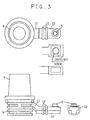
- FIG. 3 is an enlarged view illustrating an example of the connection forms between the main terminal 4 and the bushing 9, and between the connection member 10 and the auxiliary terminal 6.
- the connection member 10 extends downward from the bushing 9 to a horizontal portion of the connection member 10.
- a downwardly extending portion 11 of the connection member 10, which extends downward from the bushing 9, can thus allow the connection member 10 to be connected to an upper portion of the bushing 9.
- the bushing 9 is joined to a post of a plate pack. Dilute sulfuric acid as electrolyte tends to move upward through the surface of the post and further the surface of the bushing 9.
- the connection member 10 having a structure of this embodiment as illustrated in FIG. 3 is joined to the upper portion of the bushing 9 so as to have the distance through which electrolyte moves upward increased, so that electrolyte can be prevented from moving upward to the surface of the connection member 10.
- FIG. 4 is a view illustrating another embodiment of the present invention.
- the lid 2 has on its top a recess 8, and the connection member 10, which is molded monolithically with the bushing 9, is located in the recess 8.
- This recess 8 is then filled with for example a thermosetting resin such as epoxy resin. With this resin cured, the connection member 10 is embedded in resin 13 while only the auxiliary terminal 6 is exposed on the surface of the resin 13.
- a ring-shaped protrusion 12 is preferably formed on a portion of the connection member 10, which portion is embedded in the lid 2 or the resin 13.
- the protrusion 12 as provided can increase the distance, through which electrolyte moves to the surface of the connection member 10, and hence prevent electrolyte from moving upward to the auxiliary terminal 6 through the surface of the connection member 10.
- the bushing 9 and the connection member 10 are formed by casting so as to be monolithical with each other.
- a bushing portion is embedded in the resin of the lid 2 in the course of molding the lid 2.
- the shape of the auxiliary terminal is not necessarily limited to a specific one in the present invention, and may be varied so as to be matched to the shape of a cord to be connected.
- a protruding terminal which looks like the auxiliary terminal 6 of FIG. 2, is suitable.
- the auxiliary terminal is preferably of a bolt shape.
- the auxiliary terminal preferably has an inwardly threaded portion, as illustrated in FIG.
- the auxiliary terminal preferably has a through-hole for receiving the end of the cord.
- auxiliary terminals are not necessarily limited to specific ones. They can be properly located by changing the length, shape and the like of the connection members.
- the auxiliary terminals may be located either on the top or a side of the lid 2.
- at least the auxiliary terminals among the main and auxiliary terminals may be located in the recess 8 of the lid. This arrangement is preferable because the auxiliary terminals can be prevented from being protruded from the top of the lid.
- auxiliary terminals are provided in addition to the main terminals
- a separate connection arrangement where, for example, a cord for an engine starting circuit is connected to the main terminals while cords for circuits for driving other electrical parts and accessories are connected to the auxiliary terminals.
- the separate connection arrangement with the main terminals located away from the auxiliary terminals can prevent the cords from being located to the limited areas.
- connection member 10 in which the connection member 10 is embedded in the inside of the lid 2 or located in the recess 8 on the top of the lid 2, the connection member 10 can be prevented from being protruded outward from the lead-acid storage battery 1. As a result, a dead space is not caused on the top of the lead-acid storage battery 1 and an excellent appearance can be produced.
- an unoccupied space of the recess 8 can be effectively utilized by incorporating a device for announcing the life of the lead-acid storage battery 1, an automobile antitheft device and the like in the recess 8 of the top of the lid 2.
- the present invention is not necessarily limited thereto.
- the present invention is applicable to a lead storage battery, alkali storage battery or the like for the use other than the automobile use.
- the auxiliary terminals which are provided in pair may be provided in two or more pairs according to needs and circumstances.
- the auxiliary terminals installed are not necessarily limited to the pair of positive and negative terminals. It is not necessary to match auxiliary positive terminals in number to auxiliary negative terminals.
- an auxiliary terminal may be provided for either positive or negative pole, so that the auxiliary terminal may be connected only to a main positive terminal.
Landscapes
- Chemical & Material Sciences (AREA)
- Chemical Kinetics & Catalysis (AREA)
- Electrochemistry (AREA)
- General Chemical & Material Sciences (AREA)
- Connection Of Batteries Or Terminals (AREA)
- Secondary Cells (AREA)
Abstract
Description
Claims (10)
- A storage battery comprising:main positive and negative terminals that are connected to a plate pack; andat least one auxiliary terminal that is connected via a connection member to at least one of the main positive and negative terminals.
- A storage battery comprising:main positive and negative terminals that are connected to a plate pack; andat least one pair of auxiliary terminals that are respectively connected via connection members to the main positive and negative terminals.
- The storage battery according to any one of claims 1 and 2, further comprising:a container for accommodation of the plate pack; anda lid for covering an opening of the container; whereinat least a portion of the connection member is embedded in the inside of the lid or located in a recess on the top of the lid.
- The storage battery according to claim 3, wherein said at least a portion of the connection member that is located in the recess on the top of the lid is embedded in resin filled and cured in the recess.
- The storage battery according to any one of claims 3 and 4, wherein said at least a portion of the connection member that is embedded in the inside of the lid or embedded in the resin filled and cured in the recess has on its side a ring-shaped protrusion.
- The storage battery according to any one of claims 3 to 5, wherein said auxiliary terminal is located in the recess on the top of the lid.
- The storage battery according to any one of claims 1 to 6, further comprising a bushing monolithically formed with each of the main positive and negative terminals, wherein said connection member is connected via the bushing to each of the main positive and negative terminals.
- The storage battery according to claim 7, wherein the connection member has a downwardly extending portion and a horizontal portion, said downwardly extending portion obliquely extending from an upper portion of the bushing to the horizontal portion.
- The storage battery according to any one of claims 7 and 8, wherein the connection member is monolithically formed with the bushing and each of the main positive and negative terminals.
- The storage battery according to any one of claims 1 to 9, wherein the connection member is made of any one of lead and lead alloy.
Applications Claiming Priority (3)
| Application Number | Priority Date | Filing Date | Title |
|---|---|---|---|
| JP2002139511 | 2002-05-15 | ||
| JP2002139511 | 2002-05-15 | ||
| PCT/JP2003/005975 WO2003098721A1 (en) | 2002-05-15 | 2003-05-14 | Battery |
Publications (2)
| Publication Number | Publication Date |
|---|---|
| EP1507300A1 true EP1507300A1 (en) | 2005-02-16 |
| EP1507300A4 EP1507300A4 (en) | 2006-09-13 |
Family
ID=29544892
Family Applications (1)
| Application Number | Title | Priority Date | Filing Date |
|---|---|---|---|
| EP03723362A Withdrawn EP1507300A4 (en) | 2002-05-15 | 2003-05-14 | Battery |
Country Status (5)
| Country | Link |
|---|---|
| US (1) | US7358702B2 (en) |
| EP (1) | EP1507300A4 (en) |
| JP (1) | JP3882174B2 (en) |
| AU (1) | AU2003235285A1 (en) |
| WO (1) | WO2003098721A1 (en) |
Families Citing this family (5)
| Publication number | Priority date | Publication date | Assignee | Title |
|---|---|---|---|---|
| WO2011078209A1 (en) | 2009-12-24 | 2011-06-30 | 株式会社Gsユアサ | Lid for storage battery, injection-molding method for the lid, storage battery with the lid, and terminal section for storage battery |
| CN102884670B (en) * | 2010-02-05 | 2014-10-29 | 阳江市名扬电子科技有限公司 | Intelligent Multifunctional Battery |
| USD731426S1 (en) * | 2012-01-16 | 2015-06-09 | Pilot Battery Co., Ltd. | Battery cover |
| US9048476B2 (en) * | 2012-07-27 | 2015-06-02 | Johnson Controls Autobatterie Gmbh & Co. Kgaa | Cover part for a rechargeable battery and rechargeable battery having a cover part such as this |
| AU2013251183B1 (en) * | 2013-10-29 | 2014-12-11 | Lee, Roger Bruce MR | Battery isolator covering original battery terminal(s) with lock out facility being fully water - dust and chemical resistant. |
Family Cites Families (23)
| Publication number | Priority date | Publication date | Assignee | Title |
|---|---|---|---|---|
| ES8609823A1 (en) * | 1985-07-22 | 1986-09-01 | Tudor Acumulador | Electric accumulator battery. |
| JPS6282566A (en) | 1985-10-07 | 1987-04-16 | Nec Corp | Phase synchronizing device |
| JPS6282566U (en) * | 1985-11-12 | 1987-05-26 | ||
| JPS62229758A (en) | 1986-03-31 | 1987-10-08 | Yuasa Battery Co Ltd | Lead-acid battery |
| JPH0231063A (en) | 1988-07-19 | 1990-02-01 | Nissan Motor Co Ltd | Automatic engine brake controlling device for automatic transmission |
| JP2505629B2 (en) | 1990-07-31 | 1996-06-12 | 三菱電機エンジニアリング株式会社 | Pasting device |
| JP2587314B2 (en) | 1990-08-27 | 1997-03-05 | 伊勢電子工業株式会社 | Light source tubes for imaging devices |
| JPH0488661U (en) * | 1990-12-19 | 1992-07-31 | ||
| JP3135006B2 (en) | 1992-03-10 | 2001-02-13 | 矢崎総業株式会社 | Automotive power distribution equipment |
| JP3219527B2 (en) | 1993-03-25 | 2001-10-15 | 三洋電機株式会社 | Information processing device |
| JPH0722460A (en) | 1993-07-06 | 1995-01-24 | Hitachi Ltd | Semiconductor device |
| JPH0757720A (en) | 1993-08-17 | 1995-03-03 | Yuasa Corp | Lead-acid battery |
| DE9419278U1 (en) | 1994-12-02 | 1995-01-26 | VB Autobatterie GmbH, 30419 Hannover | Accumulator battery |
| NZ270723A (en) * | 1995-03-15 | 1998-06-26 | Glorywin Int Group Ltd | Auxiliary and cranking batteries in same box |
| JPH08329924A (en) | 1995-06-01 | 1996-12-13 | Japan Storage Battery Co Ltd | Storage battery |
| JPH09147817A (en) | 1995-11-22 | 1997-06-06 | Yuasa Corp | Lead storage battery |
| US5939861A (en) * | 1996-05-24 | 1999-08-17 | Hino Jidosha Kogyo Kabushiki Kaisha | Control system for on-vehicle battery |
| JPH10270009A (en) * | 1997-03-25 | 1998-10-09 | Honda Motor Co Ltd | Battery |
| JPH1116622A (en) | 1997-06-26 | 1999-01-22 | Sumitomo Wiring Syst Ltd | Battery terminal |
| US6121750A (en) * | 1997-12-09 | 2000-09-19 | Glory Win International Group Limited | Two terminal battery |
| US5877609A (en) * | 1998-01-23 | 1999-03-02 | Esoteric Audio Usa | Battery with multi-connection terminals and integral fuse |
| JP4601109B2 (en) | 2000-02-01 | 2010-12-22 | 株式会社Kri | Non-aqueous secondary battery |
| US20030039882A1 (en) * | 2001-01-26 | 2003-02-27 | Wruck William J. | Reverse polarity termination adaptor |
-
2003
- 2003-05-14 EP EP03723362A patent/EP1507300A4/en not_active Withdrawn
- 2003-05-14 AU AU2003235285A patent/AU2003235285A1/en not_active Abandoned
- 2003-05-14 US US10/517,279 patent/US7358702B2/en not_active Expired - Lifetime
- 2003-05-14 WO PCT/JP2003/005975 patent/WO2003098721A1/en not_active Ceased
- 2003-05-14 JP JP2004506111A patent/JP3882174B2/en not_active Expired - Fee Related
Also Published As
| Publication number | Publication date |
|---|---|
| EP1507300A4 (en) | 2006-09-13 |
| WO2003098721A1 (en) | 2003-11-27 |
| US20050175893A1 (en) | 2005-08-11 |
| US7358702B2 (en) | 2008-04-15 |
| AU2003235285A1 (en) | 2003-12-02 |
| JPWO2003098721A1 (en) | 2005-09-22 |
| JP3882174B2 (en) | 2007-02-14 |
Similar Documents
| Publication | Publication Date | Title |
|---|---|---|
| CN105518903B (en) | System, the method and apparatus that constant current relay for battery module controls | |
| US11050183B2 (en) | Electrical device | |
| US9533639B2 (en) | High voltage connector system and method | |
| US10608385B2 (en) | Connector structure and electric vehicle | |
| US10666002B2 (en) | Wiring harness connecting structure for housed circuit assembly | |
| US11545820B2 (en) | Electrical connection box | |
| US20130037317A1 (en) | Assembly structure of electrical junction box | |
| KR101230080B1 (en) | battery terminal connecting apparatus for automobile | |
| US7358702B2 (en) | Storage battery with auxiliary terminals | |
| US9508518B2 (en) | Fuse unit | |
| US20130122751A1 (en) | Connection system for establishing electrical connection between electrical device for automotive industry and at least one pair of cables | |
| US11019740B2 (en) | Electrical connection box | |
| US10516243B2 (en) | Wire harness connecting structure for two circuit assemblies | |
| KR101869547B1 (en) | Junction box | |
| CN223131858U (en) | High voltage distribution box, electric drive system and vehicle | |
| CN215835628U (en) | Casing, front drive power assembly, back drive power assembly and vehicle | |
| KR101052774B1 (en) | Connecting device of battery cable of vehicle and starting, charging and discharging cable | |
| KR200368550Y1 (en) | battery spiral structure | |
| KR20240176347A (en) | Power distribution unit for electric vehicles | |
| KR20180051451A (en) | Junction box | |
| KR19990002981U (en) | Leaving prevention structure of battery cable for automobile |
Legal Events
| Date | Code | Title | Description |
|---|---|---|---|
| PUAI | Public reference made under article 153(3) epc to a published international application that has entered the european phase |
Free format text: ORIGINAL CODE: 0009012 |
|
| AK | Designated contracting states |
Kind code of ref document: A1 Designated state(s): AT BE BG CH CY CZ DE DK EE ES FI FR GB GR HU IE IT LI LU MC NL PT RO SE SI SK TR |
|
| AX | Request for extension of the european patent |
Extension state: AL LT LV MK |
|
| 17P | Request for examination filed |
Effective date: 20041215 |
|
| DAX | Request for extension of the european patent (deleted) | ||
| RAP1 | Party data changed (applicant data changed or rights of an application transferred) |
Owner name: GS YUASA CORPORATION |
|
| RBV | Designated contracting states (corrected) |
Designated state(s): DE FR GB |
|
| A4 | Supplementary search report drawn up and despatched |
Effective date: 20060817 |
|
| RIC1 | Information provided on ipc code assigned before grant |
Ipc: H01M 2/04 20060101ALI20060810BHEP Ipc: H01M 2/30 20060101AFI20031204BHEP |
|
| 17Q | First examination report despatched |
Effective date: 20070402 |
|
| STAA | Information on the status of an ep patent application or granted ep patent |
Free format text: STATUS: THE APPLICATION IS DEEMED TO BE WITHDRAWN |
|
| 18D | Application deemed to be withdrawn |
Effective date: 20071018 |