EP1505853A2 - Electret condenser microphone - Google Patents
Electret condenser microphone Download PDFInfo
- Publication number
- EP1505853A2 EP1505853A2 EP04253206A EP04253206A EP1505853A2 EP 1505853 A2 EP1505853 A2 EP 1505853A2 EP 04253206 A EP04253206 A EP 04253206A EP 04253206 A EP04253206 A EP 04253206A EP 1505853 A2 EP1505853 A2 EP 1505853A2
- Authority
- EP
- European Patent Office
- Prior art keywords
- microphone
- diaphragm
- inlet port
- housing
- sound inlet
- Prior art date
- Legal status (The legal status is an assumption and is not a legal conclusion. Google has not performed a legal analysis and makes no representation as to the accuracy of the status listed.)
- Withdrawn
Links
Images


Classifications
-
- H—ELECTRICITY
- H04—ELECTRIC COMMUNICATION TECHNIQUE
- H04R—LOUDSPEAKERS, MICROPHONES, GRAMOPHONE PICK-UPS OR LIKE ACOUSTIC ELECTROMECHANICAL TRANSDUCERS; ELECTRIC HEARING AIDS; PUBLIC ADDRESS SYSTEMS
- H04R19/00—Electrostatic transducers
- H04R19/01—Electrostatic transducers characterised by the use of electrets
- H04R19/016—Electrostatic transducers characterised by the use of electrets for microphones
-
- H—ELECTRICITY
- H04—ELECTRIC COMMUNICATION TECHNIQUE
- H04R—LOUDSPEAKERS, MICROPHONES, GRAMOPHONE PICK-UPS OR LIKE ACOUSTIC ELECTROMECHANICAL TRANSDUCERS; ELECTRIC HEARING AIDS; PUBLIC ADDRESS SYSTEMS
- H04R19/00—Electrostatic transducers
- H04R19/04—Microphones
-
- H—ELECTRICITY
- H04—ELECTRIC COMMUNICATION TECHNIQUE
- H04R—LOUDSPEAKERS, MICROPHONES, GRAMOPHONE PICK-UPS OR LIKE ACOUSTIC ELECTROMECHANICAL TRANSDUCERS; ELECTRIC HEARING AIDS; PUBLIC ADDRESS SYSTEMS
- H04R1/00—Details of transducers, loudspeakers or microphones
- H04R1/02—Casings; Cabinets ; Supports therefor; Mountings therein
- H04R1/04—Structural association of microphone with electric circuitry therefor
-
- H—ELECTRICITY
- H04—ELECTRIC COMMUNICATION TECHNIQUE
- H04R—LOUDSPEAKERS, MICROPHONES, GRAMOPHONE PICK-UPS OR LIKE ACOUSTIC ELECTROMECHANICAL TRANSDUCERS; ELECTRIC HEARING AIDS; PUBLIC ADDRESS SYSTEMS
- H04R1/00—Details of transducers, loudspeakers or microphones
- H04R1/20—Arrangements for obtaining desired frequency or directional characteristics
- H04R1/32—Arrangements for obtaining desired frequency or directional characteristics for obtaining desired directional characteristic only
- H04R1/34—Arrangements for obtaining desired frequency or directional characteristics for obtaining desired directional characteristic only by using a single transducer with sound reflecting, diffracting, directing or guiding means
- H04R1/38—Arrangements for obtaining desired frequency or directional characteristics for obtaining desired directional characteristic only by using a single transducer with sound reflecting, diffracting, directing or guiding means in which sound waves act upon both sides of a diaphragm and incorporating acoustic phase-shifting means, e.g. pressure-gradient microphone
-
- H—ELECTRICITY
- H04—ELECTRIC COMMUNICATION TECHNIQUE
- H04R—LOUDSPEAKERS, MICROPHONES, GRAMOPHONE PICK-UPS OR LIKE ACOUSTIC ELECTROMECHANICAL TRANSDUCERS; ELECTRIC HEARING AIDS; PUBLIC ADDRESS SYSTEMS
- H04R31/00—Apparatus or processes specially adapted for the manufacture of transducers or diaphragms therefor
- H04R31/006—Interconnection of transducer parts
Definitions
- This patent relates to microphones, and more particularly, to electret condenser microphones incorporating an acoustic resistive element.
- Unidirectional electret condenser microphones typically include a housing, a diaphragm and a ring assembly, a backplate, and a spacer separating the diaphragm and ring assembly from the backplate.
- the ECM may also include an amplifier that may be disposed on a printed circuit board electrically coupled to the backplate. These components are mounted within the housing.
- One way in which ECMs operate is by allowing acoustic vibrations to enter the housing and allowing the diaphragm to vibrate in response thereto.
- the vibrating diaphragm causes a capacitance change between the diaphragm and the backplate that may be detected as an electrical signal.
- the electrical signal is coupled to the amplifier by a suitable conductor, such as wire, to produce an output from the ECM.
- the unidirectional ECM should provide a high performance and control so that the sound coming from the front of the microphone is reinforced and the sound coming from the back is canceled.
- a unidirectional ECM may be made directional in order to enhance the performance with respect to sound coming from the front of the microphone by adding a second sound inlet port, such that there is one at the front and one at the back of the ECM.
- the sound entering from the front of the microphone goes directly to the diaphragm.
- the sound entering from the back of the microphone is delayed by a resistive/capacitive (RC) acoustic network. This delay is made so that the sound coming from the front of the microphone is reinforced and the sound from the back is cancelled.
- RC resistive/capacitive
- an acoustic resistive material may be disposed between the second sound inlet port and the diaphragm.
- This material may be made of sintered plastics, plastic felts, laser drilled disks, and the sound is made to travel through the material perpendicular to a plane of the material. That is, the material is typically provided in the form of a sheet or layer having a first surface and a second surface. The sound is then made to travel substantially perpendicular to the first and second surfaces.
- the acoustic resistive material has several disadvantages.
- the acoustic resistive materials often have a relatively large amount of variability that has a great effect on the directional performance of the microphone, with laser drilled disks providing the least amount of variability of the currently available materials but at higher cost.
- the physical volume of the material places limits on the size of the ECM making size reductions difficult.
- FIG. 2 is a bottom view of the ECM shown in FIG. 1;
- FIG. 3 is a cross-sectional view taken along line 3-3 of FIG. 2;
- FIG. 5 is a top view of a metal wire cloth that may be used in an ECM.
- FIG. 6 is a cross-section view taken along line 6-6 of FIG. 5.
- an ECM may include a housing for the microphone.
- the housing may have a first sound inlet port and a second sound inlet port separate from and spaced apart from the first sound inlet port.
- a diaphragm may be disposed within the housing with the diaphragm having a first side and a second side. The first side of the diaphragm may be acoustically coupled to the first sound inlet port and the second side of the diaphragm may be acoustically coupled to the second sound inlet port.
- An acoustic resistive element may be disposed within the housing and between the second sound inlet port and the second side of the diaphragm.
- the acoustic resistive element may have a first surface and a second surface separate and spaced apart from the first surface and a first edge extending between the first surface and the second surface and a second edge extending between the first surface and the second surface.
- the first edge may be acoustically communicatively coupled to the second inlet port and the second edge may be acoustically communicatively coupled to the second side of the diaphragm, wherein sound is caused to be communicated from the second sound inlet port to the second side of the diaphragm via the acoustic resistive element and from the first edge of the acoustic resistive element to the second edge of the acoustic resistive element.
- an ECM may include a housing for the microphone.
- the housing may have a first sound inlet port and a second sound inlet port separate from and spaced apart from the first sound inlet port.
- a diaphragm may be disposed within the housing with the diaphragm having a first side and a second side. The first side of the diaphragm may be acoustically coupled to the first sound inlet port and the second side of the diaphragm may be coupled to the second sound inlet port.
- An acoustic resistive element may be disposed within the housing and between the second sound inlet port and a chamber adjacent the second side of the diaphragm.
- the acoustic resistive element may be formed to include a flange portion having outer edge and an inner edge.
- the outer edge may be acoustically communicatively coupled to the second sound inlet and the inner edge may be acoustically communicatively couple to the chamber to form a resistance-capacitance network.
- an ECM may include a housing for the microphone with the housing having a sound inlet port.
- a diaphragm may be disposed within the housing, and the diaphragm may be acoustically coupled to the sound inlet port.
- An acoustic resistive element may be disposed within the housing and between the sound inlet port and the diaphragm.
- a backplate may be coupled to the diaphragm for converting motion of the diaphragm into an electrical signal.
- An amplifier may also be provided to provide an output from the ECM, and the acoustic resistive material may electrically couple the backplate and the amplifier.
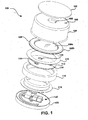
- a unidirectional electret condenser microphone (ECM) 100 may include a housing 101 including a cup-shaped housing section 104, and a bottom housing section 120.
- the cup-shaped housing section 104 and the bottom housing section 120 may be joined together by crimping, welding or adhesive bonding, for instance.
- the housing 101 may be made of a conductive material, or to have a conductive material coating thereon. In the embodiment shown, the housing 101 is made of aluminum.
- a through hole or sound port 106 is formed on a surface 105 of the cup-shaped housing section 104 as shown in FIG. 1 to allow sound to enter a chamber 109.
- a dust guard 102 which is typically made of cloth or felt is adhered to the cup-shaped housing section 104 with an adhesive to cover the through hole 106 for preventing debris from entering the microphone 100.
- the microphone 100 further includes a ring assembly 108 disposed on a base surface 107 of the cup-shaped housing portion 104.
- the ring assembly 108 includes a vibratory diaphragm 108a connected to a ring member 108b or diaphragm support.
- the ring member 108b may be made of stainless steel; however, any conductive material or material including a conductive coating, including brass or tin may be utilized.
- the vibratory diaphragm 108a of the ring assembly 108 must be capable of vibrating in response to sound waves. As such, the vibratory diaphragm 108a may be made of a thin polymer film.
- the diaphragm may be a 6 gauge thick polyethylene terephthalate film, commonly available under the trademark MYLAR, or of any similar material.
- the vibratory diaphragm 108a is adhered to the ring member 108b of the ring assembly 108.
- the microphone 100 still further includes a spacer 110 disposed between the ring assembly 108 and a backplate 112 for separating the ring assembly 108 from the backplate 112.
- the thickness of the spacer 110 sets the spacing between the ring assembly 108 and the backplate 112.
- the backplate 112 may be formed to include a plurality of sound holes 114 to allow the sound vibrations that enter the housing 101 to vibrate the diaphragm 108a.
- the backplate 112 may be made of stainless steel.
- the spacer 110 is disposed between the ring assembly 108 and the wall of the housing 101 to electrically isolate the vibratory diaphragm 108a from the housing 101.
- the spacer 110 is generally made of a non-conductive material, and for example may be made of a 200 gauge Mylar plastic. As shown in FIG. 1, the spacer 110 provides for spacing the backplate 112 a set distance from the ring assembly 108. This distance provides a defined gap between the backplate 112 and the vibratory diaphragm 108a, enabling air movement between the diaphragm 108a and the backplate 112.
- the dielectric film or electret material on the backplate 112 cooperates with the vibratory diaphragm 108a to develop an electric signal representative of the acoustic energy incident on the diaphragm 108a.
- the operation of the microphone 100 is based on the change in capacitance between a fixed electrode, the backplate 112, and a movable electrode, the vibratory diaphragm 108a, under the influence of external air (sound) vibrations.
- the change in this capacitance is proportional to the changes in air pressure and can be converted into amplified sound vibrations via the electronic amplifier 122.
- the amplifier 122 then converts and amplifies the changes in capacitance into an electrical signal representative of those changes.
- the microphone 100 may also include additional sound inlet ports 130 shown in FIGs. 2-4.
- the sound inlet ports 130 formed on the back of the microphone 100, for example by not completely crimping a flange 132 on the cup-shaped housing portion 104 at selected areas around the circumference of the flange 132, are acoustically coupled to a second chamber 144 adjacent the diaphragm 108a.
- an acoustic resistive element 118 is provided to affect additive combining of sound energy received at the front of the microphone 100 and to cancel sound energy received at the back of the microphone.
- the acoustic resistive element 118 may be woven metal, sintered metal, felted metal, woven plastic, sintered plastic, felted plastic, woven organic fiber, sintered organic fiber, felted organic fiber.
- the acoustic resistive material is conductive wire cloth, such as stainless steel cloth.
- the acoustic resistive element 118 may also function to electrically interconnect the backplate 112 and electronic amplifier 122, which is placed across the top surface 136 of the bottom housing 120 of the housing 101.
- the acoustic resistive, element 118 is disposed between the electronic amplifier 122 and the backplate 112.
- the acoustic resistive element 118 is formed with a top hat-like shape, with a flange or disk portion 111 and a wall or cylinder portion 113 with a lip 115.
- Flange portion 111 electrically couples to the amplifier circuit board 112, while the lip 115 conductively engages the backplate 112 thereby electrically connecting the backplate 112 to the components on amplifier circuit board 122.
- the backplate 112 is in electrical connection with ground through the conductive portions of the support member 116 and the housing 101.
- the acoustic resistive element 118 may made of a conductive metal cloth such as stainless steel; however any conductive material or material having a conductive coating may be utilized in the embodiments of the ECM wherein the acoustic resistive material 118 further serves to provide electrical coupling of the backplate 112 and the amplifier 122.
- the acoustic resistive element also acts to delay sound entering from the bottom housing section 120 through sound inlet ports 130. This sound passes around the amplifier circuit board 122 and enters a second chamber 144 via the acoustic resistive element 118. More particularly, the flange portion 111 of the acoustic resistive element has a first surface 136, second surface 138, a first edge 140 and a second edge 142. A sound path is created within the housing 101 such that the sound is caused to enter the acoustic resistive element 118 at the first edge 140, to travel through flange portion 111 substantially parallel to the surfaces 136 and 138, to exit the acoustic resistive material via the second edge 142 and to enter the second chamber 144.
- the chamber 144 may be configured as a relatively large acoustic volume that acts as the capacitance, "C", of the resitance-capacitance, "RC", network. By increasing the capacitance value, the resistance may be made smaller, and hence easier to control. A consistent value of R may be obtained by using wire cloth, as described, and by arranging the acoustic path such that the sound travels from the edge 140 to the edge 142.
- the acoustic resistive element 118 enables setting of the directivity of the microphone 100 as is well known in the art by tuning the RC value of the RC network formed by the acoustic resistive element 118 and the second chamber 144.
Landscapes
- Engineering & Computer Science (AREA)
- Physics & Mathematics (AREA)
- Acoustics & Sound (AREA)
- Signal Processing (AREA)
- Health & Medical Sciences (AREA)
- Otolaryngology (AREA)
- Manufacturing & Machinery (AREA)
- Electrostatic, Electromagnetic, Magneto- Strictive, And Variable-Resistance Transducers (AREA)
Abstract
Description
Claims (18)
- A microphone comprising:a housing for the microphone, the housing having a first sound inlet port and a second sound inlet port separate from and spaced apart from the first sound inlet port;a diaphragm disposed within the housing, the diaphragm having a first side and a second side; the first side being acoustically coupled to the first sound inlet port and the second side being acoustically coupled to the second sound inlet port; andan acoustic resistive element disposed within the housing and between the second sound inlet port and a chamber adjacent the second side of the diaphragm, the acoustic resistive element having flange portion including a first surface and a second surface separate and spaced apart from the first surface, a first edge extending between the first surface and the second surface and a second edge extending between the first surface and the second surface, wherein the first edge is acoustically communicatively coupled to the second inlet port and the second edge is acoustically communicatively coupled to the chamber, wherein sound pressure is caused to be communicated from second sound inlet port to the chamber via the acoustic resistive element and from the first edge of the acoustic resistive element to the second edge of the acoustic resistive element.
- The microphone of claim 1, wherein the flange and the chamber form a resistance-capacitance delay network.
- The microphone of claim 1, wherein at least one of the first surface and the second surface is non-planar.
- The microphone of claim 1, wherein the first and second surfaces are substantially planar and parallel and wherein the first and second edges extend between the first and second surface.
- The microphone of clam 4, wherein the first and second edges are substantially perpendicular to the first and second surfaces.
- The microphone of claim 1, wherein the acoustic resistive element comprises a disk of acoustic resistive material, the first edge comprises an outer edge of the disk and the second edge comprises an edge surface defined by a bore extending through the disk.
- The microphone of claim 1, wherein the disk is annular.
- The microphone of claim 1, wherein the acoustic resistive material comprises at least one of: woven metal, sintered metal, felted metal, woven plastic, sintered plastic, felted plastic, woven organic fiber, sintered organic fiber, and felted organic fiber.
- The microphone of claim 1, further comprising a backplate coupled to the diaphragm for converting motion of the diaphragm into an electrical signal and an amplifier; wherein the acoustic resistive material electrically couples the backplate and the amplifier.
- A microphone comprising:a housing for the microphone, the housing having a first sound inlet port and a second sound inlet port separate from and spaced apart from the first sound inlet port;a diaphragm disposed within the housing, the diaphragm having a first side and a second side; the first side being acoustically coupled to the first sound inlet port and the second side being coupled to the second sound inlet port; anda resistive-capacitive network comprising an acoustic resistive element and a chamber adjacent the second side of the diaphragm, the resistive capacitive element being disposed within the housing and between the second sound inlet port and the chamber, the acoustic resistive element formed to include a flange portion having an outer edge and an inner edge, such that sound is caused to travel through the flange portion to the chamber from the outer edge to the inner edge.
- The microphone of claim 10, wherein acoustic resistive element is circular.
- The microphone of claim 10, wherein the acoustic resistive material comprises at least one of: woven metal, sintered metal, felted metal, woven plastic, sintered plastic, felted plastic, woven organic fiber, sintered organic fiber, and felted organic fiber.
- The microphone of claim 10, further comprising a backplate coupled to the diaphragm for converting motion of the diaphragm into an electrical signal and an amplifier; wherein the acoustic resistive material electrically couples the backplate and the amplifier.
- The microphone of claim 14, wherein the acoustic resistive element comprises a wall portion extending from the flange, the wall portion electrically engaging the backplate and the flange portion electrically engaging the amplifier.
- The microphone of claim 14, wherein the wall portion is cylindrical.
- A microphone comprising:a housing for the microphone, the housing having a sound inlet port;a diaphragm disposed within the housing, the diaphragm acoustically coupled to the sound inlet port;an acoustic resistive element disposed within the housing and between the sound inlet port and the diaphragm;a backplate coupled to the diaphragm for converting motion of the diaphragm into an electrical signal; andan amplifier; wherein the acoustic resistive material electrically couples the backplate and the amplifier.
- The microphone of claim 16, wherein the acoustic resistive material comprises at least one of: woven metal, sintered metal, felted metal, woven conductive plastic, sintered conductive plastic, felted conductive plastic, woven conductive organic fiber, sintered conductive organic fiber, felted conductive organic fiber.
- The microphone of claim 16, wherein the acoustic resistive element is formed from a volume of acoustic resistive material having an outer surface and an inner surface, the inner surface substantially contained within the volume, the outer surface being acoustically communicatively coupled to the sound inlet and the inner surface being acoustically communicatively couple to the diaphragm.
Applications Claiming Priority (2)
| Application Number | Priority Date | Filing Date | Title |
|---|---|---|---|
| US10/634,552 US7136500B2 (en) | 2003-08-05 | 2003-08-05 | Electret condenser microphone |
| US634552 | 2003-08-05 |
Publications (2)
| Publication Number | Publication Date |
|---|---|
| EP1505853A2 true EP1505853A2 (en) | 2005-02-09 |
| EP1505853A3 EP1505853A3 (en) | 2005-10-05 |
Family
ID=33552915
Family Applications (1)
| Application Number | Title | Priority Date | Filing Date |
|---|---|---|---|
| EP04253206A Withdrawn EP1505853A3 (en) | 2003-08-05 | 2004-05-28 | Electret condenser microphone |
Country Status (6)
| Country | Link |
|---|---|
| US (2) | US7136500B2 (en) |
| EP (1) | EP1505853A3 (en) |
| JP (1) | JP3971763B2 (en) |
| KR (1) | KR20050016010A (en) |
| CN (1) | CN1582063A (en) |
| TW (1) | TWI268116B (en) |
Cited By (3)
| Publication number | Priority date | Publication date | Assignee | Title |
|---|---|---|---|---|
| KR100638512B1 (en) | 2005-10-14 | 2006-10-25 | 주식회사 비에스이 | Metal Mesh Phase Delay Device and Condenser Microphone |
| CN102256199A (en) * | 2010-10-12 | 2011-11-23 | 歌尔声学股份有限公司 | Micro capacitance microphone |
| EP2323421A4 (en) * | 2008-07-30 | 2013-03-13 | Funai Electric Co | Microphone unit and cellular phone provided with same |
Families Citing this family (40)
| Publication number | Priority date | Publication date | Assignee | Title |
|---|---|---|---|---|
| US7136500B2 (en) * | 2003-08-05 | 2006-11-14 | Knowles Electronics, Llc. | Electret condenser microphone |
| JP2005130437A (en) * | 2003-10-24 | 2005-05-19 | Knowles Electronics Llc | High-performance capacitor microphone and its manufacturing method |
| KR100675026B1 (en) * | 2003-11-05 | 2007-01-29 | 주식회사 비에스이 | How to mount a condenser microphone on the main PC |
| KR100556684B1 (en) * | 2004-01-20 | 2006-03-10 | 주식회사 비에스이 | Condenser microphone suitable for mounting on the main PC |
| JP4503421B2 (en) * | 2004-11-25 | 2010-07-14 | 株式会社オーディオテクニカ | Condenser microphone |
| KR100675510B1 (en) * | 2005-04-25 | 2007-01-30 | 주식회사 비에스이 | Dual bass and electret condenser microphone |
| US20060245606A1 (en) * | 2005-04-27 | 2006-11-02 | Knowles Electronics, Llc | Electret condenser microphone and manufacturing method thereof |
| US20070003081A1 (en) * | 2005-06-30 | 2007-01-04 | Insound Medical, Inc. | Moisture resistant microphone |
| US20070041596A1 (en) * | 2005-08-09 | 2007-02-22 | David Pan | Condenser microphone |
| CN101060726B (en) * | 2006-04-21 | 2011-10-12 | 探微科技股份有限公司 | Method of making a diaphragm of a condenser microphone element |
| KR100797440B1 (en) * | 2006-09-05 | 2008-01-23 | 주식회사 비에스이 | Square tube shaped electret condenser microphone |
| CN1946249B (en) * | 2006-09-13 | 2012-01-11 | 山西太微电声科技有限公司 | Skin touch type capacitor vibration pickup device |
| CN101146375B (en) * | 2006-09-14 | 2012-03-28 | 东莞泉声电子有限公司 | Miniature condenser microphone |
| US20080101640A1 (en) * | 2006-10-31 | 2008-05-01 | Knowles Electronics, Llc | Electroacoustic system and method of manufacturing thereof |
| JP2009005253A (en) * | 2007-06-25 | 2009-01-08 | Hosiden Corp | Condenser microphone |
| USD574368S1 (en) * | 2007-09-19 | 2008-08-05 | Innotech Pty Ltd. | Loudspeaker assembly |
| CN101272637B (en) * | 2008-04-22 | 2012-06-27 | 华英伦电子(宁波)有限公司 | Electret capacitor type microphone with integral vocal cavity component |
| JP4960921B2 (en) * | 2008-04-25 | 2012-06-27 | ホシデン株式会社 | Electret condenser microphone |
| WO2010045088A2 (en) * | 2008-10-17 | 2010-04-22 | Knowles Electronics, Llc | Apparatus and method for reducing crosstalk within a microphone |
| TWI477156B (en) * | 2008-12-17 | 2015-03-11 | Goertek Inc | Miniature condenser microphone |
| TWI492639B (en) * | 2009-01-12 | 2015-07-11 | Merry Electronics Co Ltd | Electret condenser microphone |
| WO2010124099A2 (en) * | 2009-04-23 | 2010-10-28 | Knowles Electronics, Llc | Microphone having diaphragm ring with increased stability |
| JP5404220B2 (en) * | 2009-07-09 | 2014-01-29 | 株式会社オーディオテクニカ | Condenser microphone |
| JP5410333B2 (en) * | 2010-02-24 | 2014-02-05 | 株式会社オーディオテクニカ | Unidirectional condenser microphone |
| US20130044899A1 (en) * | 2011-08-15 | 2013-02-21 | Harman International Industries, Inc. | Dual Backplate Microphone |
| JP5917188B2 (en) * | 2012-02-24 | 2016-05-11 | 株式会社オーディオテクニカ | Dynamic microphone unit, method of manufacturing magnetic circuit unit for dynamic microphone, and dynamic microphone |
| US9398389B2 (en) | 2013-05-13 | 2016-07-19 | Knowles Electronics, Llc | Apparatus for securing components in an electret condenser microphone (ECM) |
| USD743382S1 (en) * | 2013-09-20 | 2015-11-17 | Panasonic Intellectual Property Management Co., Ltd. | Microphone |
| JP6270626B2 (en) * | 2014-05-23 | 2018-01-31 | 株式会社オーディオテクニカ | Variable directivity electret condenser microphone |
| US9888322B2 (en) | 2014-12-05 | 2018-02-06 | Knowles Electronics, Llc | Receiver with coil wound on a stationary ferromagnetic core |
| JP6433357B2 (en) * | 2015-03-26 | 2018-12-05 | 株式会社オーディオテクニカ | Boundary microphone |
| US9401158B1 (en) | 2015-09-14 | 2016-07-26 | Knowles Electronics, Llc | Microphone signal fusion |
| US9830930B2 (en) | 2015-12-30 | 2017-11-28 | Knowles Electronics, Llc | Voice-enhanced awareness mode |
| US9779716B2 (en) | 2015-12-30 | 2017-10-03 | Knowles Electronics, Llc | Occlusion reduction and active noise reduction based on seal quality |
| US9812149B2 (en) | 2016-01-28 | 2017-11-07 | Knowles Electronics, Llc | Methods and systems for providing consistency in noise reduction during speech and non-speech periods |
| US11082778B2 (en) | 2016-03-18 | 2021-08-03 | Knowles Electronics, Llc | Driver with acoustic filter chamber |
| EP3501185A4 (en) * | 2016-08-18 | 2020-03-18 | Harman International Industries, Incorporated | ELECTRIC CONDENSER MICROPHONE AND MANUFACTURING METHOD THEREFOR |
| US11785375B2 (en) | 2021-06-15 | 2023-10-10 | Quiet, Inc. | Precisely controlled microphone acoustic attenuator with protective microphone enclosure |
| US12445761B2 (en) | 2021-06-15 | 2025-10-14 | Quiet, Inc. | Precisely controlled microphone acoustic attenuator with protective microphone enclosure |
| USD1121601S1 (en) * | 2023-11-10 | 2026-04-07 | Dzine Products, LLC | Microphone mount |
Family Cites Families (9)
| Publication number | Priority date | Publication date | Assignee | Title |
|---|---|---|---|---|
| DE1011467B (en) * | 1954-08-13 | 1957-07-04 | Schoeps Dr Ing Karl | Switchable condenser microphone |
| JPS5756640Y2 (en) * | 1978-09-30 | 1982-12-06 | ||
| JPS622879Y2 (en) * | 1981-03-25 | 1987-01-22 | ||
| TW274675B (en) * | 1992-09-08 | 1996-04-21 | Motorola Inc | |
| JP3479464B2 (en) | 1999-02-08 | 2003-12-15 | ホシデン株式会社 | Unidirectional electret condenser microphone |
| US7065224B2 (en) | 2001-09-28 | 2006-06-20 | Sonionmicrotronic Nederland B.V. | Microphone for a hearing aid or listening device with improved internal damping and foreign material protection |
| JP2003230195A (en) * | 2002-02-06 | 2003-08-15 | Hosiden Corp | Electret capacitor microphone |
| JP3908059B2 (en) * | 2002-02-27 | 2007-04-25 | スター精密株式会社 | Electret condenser microphone |
| US7136500B2 (en) * | 2003-08-05 | 2006-11-14 | Knowles Electronics, Llc. | Electret condenser microphone |
-
2003
- 2003-08-05 US US10/634,552 patent/US7136500B2/en not_active Expired - Fee Related
-
2004
- 2004-05-27 TW TW093115116A patent/TWI268116B/en not_active IP Right Cessation
- 2004-05-28 EP EP04253206A patent/EP1505853A3/en not_active Withdrawn
- 2004-07-22 KR KR1020040057079A patent/KR20050016010A/en not_active Ceased
- 2004-08-04 JP JP2004227601A patent/JP3971763B2/en not_active Expired - Fee Related
- 2004-08-05 CN CN200410070055.6A patent/CN1582063A/en active Pending
-
2006
- 2006-09-08 US US11/530,192 patent/US20070025571A1/en not_active Abandoned
Cited By (5)
| Publication number | Priority date | Publication date | Assignee | Title |
|---|---|---|---|---|
| KR100638512B1 (en) | 2005-10-14 | 2006-10-25 | 주식회사 비에스이 | Metal Mesh Phase Delay Device and Condenser Microphone |
| WO2007043729A1 (en) * | 2005-10-14 | 2007-04-19 | Bse Co., Ltd. | Metal mesh phase delay device and condenser microphone including the same |
| EP2323421A4 (en) * | 2008-07-30 | 2013-03-13 | Funai Electric Co | Microphone unit and cellular phone provided with same |
| US8565465B2 (en) | 2008-07-30 | 2013-10-22 | Funai Electric Co., Ltd. | Microphone unit and mobile phone provided with the same |
| CN102256199A (en) * | 2010-10-12 | 2011-11-23 | 歌尔声学股份有限公司 | Micro capacitance microphone |
Also Published As
| Publication number | Publication date |
|---|---|
| US7136500B2 (en) | 2006-11-14 |
| CN1582063A (en) | 2005-02-16 |
| TWI268116B (en) | 2006-12-01 |
| JP2005057775A (en) | 2005-03-03 |
| KR20050016010A (en) | 2005-02-21 |
| JP3971763B2 (en) | 2007-09-05 |
| EP1505853A3 (en) | 2005-10-05 |
| TW200511876A (en) | 2005-03-16 |
| US20050031150A1 (en) | 2005-02-10 |
| US20070025571A1 (en) | 2007-02-01 |
Similar Documents
| Publication | Publication Date | Title |
|---|---|---|
| US7136500B2 (en) | Electret condenser microphone | |
| JP4033830B2 (en) | Microphone | |
| US7136496B2 (en) | Electret assembly for a microphone having a backplate with improved charge stability | |
| US8737661B2 (en) | Narrow directional condenser microphone | |
| CN111866633B (en) | Gradient MEMS microphone with assemblies of different heights | |
| EP1397023A2 (en) | Microphone with improved sound inlet port | |
| US8588451B2 (en) | Electret condenser microphone | |
| US20070286445A1 (en) | Microphone Assembly with Preamplifier and Manufacturing Method Thereof | |
| US6885751B2 (en) | Pressure-gradient microphone capsule | |
| CN102957992A (en) | Dual backplate microphone | |
| CN107852550B (en) | speaker unit | |
| US20080273736A1 (en) | Electrostatic microphone | |
| US8867772B2 (en) | Condenser microphone unit and condenser microphone | |
| US7184563B2 (en) | Electret condenser microphone | |
| EP3497942B1 (en) | Dual diaphragm microphone | |
| US9357313B2 (en) | Microphone unit having a plurality of diaphragms and a signal processing unit | |
| KR100464700B1 (en) | Electret condenser microphone | |
| US20150189417A1 (en) | Unidirectional condenser microphone unit | |
| KR100437681B1 (en) | Directional microphone | |
| KR200289305Y1 (en) | Directional microphone | |
| JP4737547B2 (en) | Unidirectional condenser microphone unit | |
| KR100542177B1 (en) | Unidirectional Condenser Microphone | |
| KR100542179B1 (en) | Unidirectional Condenser Microphone | |
| KR20030003139A (en) | Unidirectional condenser microphone | |
| KR100544286B1 (en) | Unidirectional Condenser Microphone |
Legal Events
| Date | Code | Title | Description |
|---|---|---|---|
| PUAI | Public reference made under article 153(3) epc to a published international application that has entered the european phase |
Free format text: ORIGINAL CODE: 0009012 |
|
| AK | Designated contracting states |
Kind code of ref document: A2 Designated state(s): AT BE BG CH CY CZ DE DK EE ES FI FR GB GR HU IE IT LI LU MC NL PL PT RO SE SI SK TR |
|
| AX | Request for extension of the european patent |
Extension state: AL HR LT LV MK |
|
| PUAL | Search report despatched |
Free format text: ORIGINAL CODE: 0009013 |
|
| AK | Designated contracting states |
Kind code of ref document: A3 Designated state(s): AT BE BG CH CY CZ DE DK EE ES FI FR GB GR HU IE IT LI LU MC NL PL PT RO SE SI SK TR |
|
| AX | Request for extension of the european patent |
Extension state: AL HR LT LV MK |
|
| RIC1 | Information provided on ipc code assigned before grant |
Ipc: 7H 04R 1/38 B Ipc: 7H 04R 19/00 A |
|
| 17P | Request for examination filed |
Effective date: 20060214 |
|
| AKX | Designation fees paid |
Designated state(s): DE DK NL PL |
|
| 17Q | First examination report despatched |
Effective date: 20070529 |
|
| STAA | Information on the status of an ep patent application or granted ep patent |
Free format text: STATUS: THE APPLICATION IS DEEMED TO BE WITHDRAWN |
|
| 18D | Application deemed to be withdrawn |
Effective date: 20101201 |