EP1505801A2 - Holster for supporting and charging a wireless peripheral of a mobile device - Google Patents
Holster for supporting and charging a wireless peripheral of a mobile device Download PDFInfo
- Publication number
- EP1505801A2 EP1505801A2 EP04254718A EP04254718A EP1505801A2 EP 1505801 A2 EP1505801 A2 EP 1505801A2 EP 04254718 A EP04254718 A EP 04254718A EP 04254718 A EP04254718 A EP 04254718A EP 1505801 A2 EP1505801 A2 EP 1505801A2
- Authority
- EP
- European Patent Office
- Prior art keywords
- holster
- mobile device
- peripheral device
- peripheral
- charging
- Prior art date
- Legal status (The legal status is an assumption and is not a legal conclusion. Google has not performed a legal analysis and makes no representation as to the accuracy of the status listed.)
- Granted
Links
Images


Classifications
-
- H—ELECTRICITY
- H02—GENERATION; CONVERSION OR DISTRIBUTION OF ELECTRIC POWER
- H02J—ELECTRIC POWER NETWORKS; CIRCUIT ARRANGEMENTS OR SYSTEMS FOR SUPPLYING OR DISTRIBUTING ELECTRIC POWER; SYSTEMS FOR STORING ELECTRIC ENERGY
- H02J7/00—Circuit arrangements for charging or discharging batteries or for supplying loads from batteries
- H02J7/70—Circuit arrangements for charging or discharging batteries or for supplying loads from batteries characterised by the mechanical construction
- H02J7/731—Circuit arrangements for charging or discharging batteries or for supplying loads from batteries characterised by the mechanical construction specially adapted for holding portable devices containing batteries
-
- A—HUMAN NECESSITIES
- A45—HAND OR TRAVELLING ARTICLES
- A45C—PURSES; LUGGAGE; HAND CARRIED BAGS
- A45C11/00—Receptacles for purposes not provided for in groups A45C1/00-A45C9/00
- A45C11/002—Receptacles for purposes not provided for in groups A45C1/00-A45C9/00 for storing portable handheld communication devices, e.g. pagers or smart phones
-
- A—HUMAN NECESSITIES
- A45—HAND OR TRAVELLING ARTICLES
- A45C—PURSES; LUGGAGE; HAND CARRIED BAGS
- A45C15/00—Purses, bags, luggage or other receptacles covered by groups A45C1/00 - A45C11/00, combined with other objects or articles
-
- A—HUMAN NECESSITIES
- A45—HAND OR TRAVELLING ARTICLES
- A45F—TRAVELLING OR CAMP EQUIPMENT: SACKS OR PACKS CARRIED ON THE BODY
- A45F5/00—Holders or carriers for hand articles; Holders or carriers for use while travelling or camping
-
- A—HUMAN NECESSITIES
- A45—HAND OR TRAVELLING ARTICLES
- A45F—TRAVELLING OR CAMP EQUIPMENT: SACKS OR PACKS CARRIED ON THE BODY
- A45F5/00—Holders or carriers for hand articles; Holders or carriers for use while travelling or camping
- A45F5/1516—Holders or carriers for portable handheld communication devices, e.g. pagers or smart phones
-
- H—ELECTRICITY
- H02—GENERATION; CONVERSION OR DISTRIBUTION OF ELECTRIC POWER
- H02J—ELECTRIC POWER NETWORKS; CIRCUIT ARRANGEMENTS OR SYSTEMS FOR SUPPLYING OR DISTRIBUTING ELECTRIC POWER; SYSTEMS FOR STORING ELECTRIC ENERGY
- H02J7/00—Circuit arrangements for charging or discharging batteries or for supplying loads from batteries
- H02J7/34—Parallel operation in networks using both storage and other DC sources, e.g. providing buffering
- H02J7/342—The other DC source being a battery actively interacting with the first one, i.e. battery to battery charging
-
- H—ELECTRICITY
- H04—ELECTRIC COMMUNICATION TECHNIQUE
- H04M—TELEPHONIC COMMUNICATION
- H04M1/00—Substation equipment, e.g. for use by subscribers
- H04M1/02—Constructional features of telephone sets
- H04M1/04—Supports for telephone transmitters or receivers
-
- H—ELECTRICITY
- H02—GENERATION; CONVERSION OR DISTRIBUTION OF ELECTRIC POWER
- H02J—ELECTRIC POWER NETWORKS; CIRCUIT ARRANGEMENTS OR SYSTEMS FOR SUPPLYING OR DISTRIBUTING ELECTRIC POWER; SYSTEMS FOR STORING ELECTRIC ENERGY
- H02J7/00—Circuit arrangements for charging or discharging batteries or for supplying loads from batteries
- H02J7/40—Circuit arrangements for charging or discharging batteries or for supplying loads from batteries characterised by the exchange of charge or discharge related data
- H02J7/42—Circuit arrangements for charging or discharging batteries or for supplying loads from batteries characterised by the exchange of charge or discharge related data with electronic devices having internal batteries, e.g. mobile phones
Definitions
- the present invention generally relates to holsters for mobile devices and their peripherals. More particularly, the present invention relates to a structure for supporting peripherals to allow them to be charged by the mobile device.
- Peripheral devices are increasingly used in conjunction with mobile electronic devices.
- Wireless headsets for example, add functionality to cellular phones.
- an increasing number of portable digital cameras are designed to interact with cellular phones and personal digital assistants.
- peripheral devices are subject to the competing requirements of power and size. There is an increasing demand for peripheral devices having a long-lasting power supply. Additionally, there is a desire to minimise peripheral size, which results in smaller batteries.
- Peripherals often use a lithium ion or a nickel metal hydride batteries as their power supply to provide long life, low weight, and rechargeability.
- Charging the batteries of a peripheral device often involves docking the batteries, possibly within the peripheral, in a charger connected to a power source such as an electrical outlet or a motor vehicle battery. Consequently, a user's enjoyment of a peripheral is limited by having to be at home, in the office, or in the car to charge the peripheral. This also results in the user having to manage the charging of two separate devices, the main unit and the peripheral device.
- Carrying cases have several pockets whereas holsters typically have a sleeve. Although the smaller size of holsters makes them desirable for holding peripherals, holsters are normally designed to hold only one item at a time, either a mobile device or a peripheral. Carrying cases hold peripherals in pockets which are closed using a fastener such as a zipper or hook and loop fastener such as those made by VelcroTM. Retrieving the peripheral entails fiddling with the fastener of a carrying case, which is cumbersome.
- a fastener such as a zipper or hook and loop fastener such as those made by VelcroTM.
- a holster for receiving and retaining a mobile device in a sleeve and a peripheral device comprises a mating structure for releasably retaining the peripheral device in electrical contact with the mobile device retained in the sleeve so as to permit the mobile device to charge a battery in the peripheral device through a charging contact.
- a holster for holding both a peripheral device and a mobile device. More specifically, the holster holds both a mobile device and a peripheral device to permit the mobile device to charge the peripheral device.
- peripheral devices such as wireless headsets or digital cameras that interface with a mobile device must carry a mobile charging station with them. This results in a net increase in the number of items a user is required to carry.
- Systems in accordance with aspects of the present invention negates the need to carry a mobile charging station by providing a holster to hold both the mobile device and the peripheral device, so that they are in electrical contact with each other, allowing the peripheral device to recharge its battery from the mobile device.
- peripheral devices typically have smaller batteries than mobile devices, and shorter battery lives.
- the holster supports the peripheral device in such a way that when the peripheral is held for charging, the mobile device can be removed for use while the peripheral device remains securely retained by the holster.
- FIG 1A shows a side view of a holster according to an embodiment of the present invention.
- Holster 20 has a back panel, a base portion 27 , and side wall portions 26 which define sleeve 22 designed for receiving a mobile device.
- a mating structure 24 in side wall 26 to allow a peripheral device to mate with a holster.
- Figure 1B shows a front view of the holster illustrated in Figure 1A.
- Holster 20 has two side walls 26 each having its own mating structure 24 , the side walls 26 helping to define the sleeve 22.
- Figure 1C illustrates the top view of the holster of the Figures 1A and 1B.
- holster 20 has a sleeve 22 defined by side walls 26.
- Each side wall 26 has a mating structure 24 .
- mating structures include retaining brackets, magnets, tabs, latches, flanges, hooks, clamps, and tongue-and-groove assemblies. Additionally, one skilled in the art will appreciate that in place of mating structure 24 there can be offered a peripheral sleeve adjacent to the sleeve 22 for holding the mobile device.
- Figure 2A illustrates a side view of the holster of Figure 1, and a mobile device 28 for being retained in the sleeve.
- Mobile device 28 has a charger 30 connected to a charging port 32 .
- Figure 2B illustrates the mobile device 28 and holster 20 from a front view.
- Figures 3A and 3B provide side and front views respectively of mobile device 28 contained in the sleeve of holster 20 .
- the sleeve retains mobile device 28 so that charger 30 , and charging port 32 are accessible from the front opening of the holster defined by the side walls 26 .
- mating structure 24 is aligned so that a peripheral device will be held on holster 20 so that it has access to both charging port 32 and charger 30 .
- FIG 4A illustrates a side view of a peripheral device 34 and holster 20 retaining mobile device 28 .
- Peripheral device 34 has two mating structure 35 and a charging contact 42 .
- mating structure 35 and charging contact 42 are accessible from the front of peripheral device 34 .
- Mating structures 35 and 24 are located so that they can connect.
- Charging contact 42 is positioned such that connecting mating structures 35 and 24 brings charging contact 42 in electrical contact with charging port 32 .
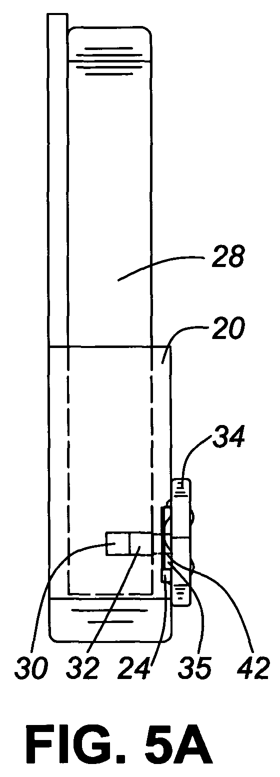
- FIGS 5A and 5B provide side and top views of peripheral device 34 mated with holster 20 and held in electrical contact with mobile device 28 .
- Holster 20 holds mobile device 28 in its sleeve as previously described.
- Peripheral device 34 uses its mating structures 35 to mate with mating structure 24 on holster 20 .
- charging contact 42 of peripheral device 34 is placed in electrical contact with charging port 32 . This allows a direct electrical contact between peripheral device 34 and mobile device 28 .
- Mobile device 28 using charger 30 and charging port 32 which in various embodiments may be integrated into a single element, provides an electrical current to peripheral device 34 through charging contact 42 . This current is used to charge the battery of peripheral device 34 .
- charger 30 of the mobile device 28 is able to charge peripheral device 34 , while peripheral device 34 is connected to holster 20 .
- peripheral device 34 is a wireless headset for use with a mobile device providing voice services.
- a headset for use with a mobile device such as a cellular phone can be recharged by the mobile device, instead of requiring either a dedicated charger, or a desktop or vehicle charger.
- peripheral device 34 is a camera, and it benefits from the same advantage previously described.
- Figure 6A illustrates a second embodiment of the present invention.
- the peripheral device charges off the mobile device through the base of the holster.
- holsters designed to retain a mobile device under rigorous movement include a supporting wall between side walls and located opposite the back panel. Unfortunately, the supporting wall prevents a peripheral device from making electrical contact with a mobile device.
- holster designs may arise where it is preferable that charging occurs through the base of the holster.
- FIG 6A shows a side view of a holster of the second embodiment of the present invention.
- Holster 20 has a back panel, side walls, and a base 27 .
- the side walls, back panel and base 27 define sleeve 22 for retaining a mobile device.
- Base 27 also includes a mating structure 24 for securing to a peripheral device.
- Base 27 of holster 20 has an aperture 36 to allow a peripheral device to make electrical contact directly with the mobile device held by sleeve 22 .
- Figure 6B provides a front view of the holster illustrated in Figure 6A.
- Holster 20 has a back panel, a sleeve 22 defined by the back panel, side walls, and base 27 .
- base 27 is a mating structure 24 for securing a peripheral device, and an aperture 36 to allow the peripheral device secured by mating structure 24 to make electrical contact with the mobile device held by sleeve 22 .
- FIG 7 illustrates the holster illustrated in Figures 6A and 6B aligned to receive a mobile device 28 .
- Mobile device 28 has charger 30 and charging port 32 located at its base to align with aperture 36 .
- Figure 8 illustrates mobile device 28 held in the sleeve of holster 20 with charging port 32 and charger 30 aligned with aperture 36 .
- Figure 9A illustrates a side view of peripheral device 34 having a retractable, or hideable arm 40 .
- Arm 40 can be retracted, or in the presently illustrated embodiment rotated into the body of peripheral device 34 so that while in use it is not exposed.
- Figure 9B illustrates a front view of peripheral device 34 , and mobile device 28 held in the sleeve of holster 20 .
- the charging port and charger of the mobile device 28 are aligned with the aperture in the base of holster 20 .
- Figure 10 illustrates a side view of the holster 20 holding mobile device 28 in its sleeve such that charger 30 and charging port 32 are in alignment with aperture 36 , and holster 20 is aligned with peripheral device 34 to allow peripheral device 34 to mate with the holster 20 .
- peripheral device 34 engages mating structure 24 with its mating structure 35 to provide a physical connection between holster 20 and peripheral device 34 .
- arm 40 is in an exposed position such that a tongue 37 can be inserted into aperture 36 so that a charging contact 42 of peripheral device 34 is aligned to make contact with electrical contact 32 of mobile device 28 .
- FIG 11 illustrates the engagement of peripheral device 34 with holster 20 .
- Mating structures 24 and 35 provide a secure fastening of peripheral device 34 to holster 20 .
- this attachment can be made using a number of known fasteners, including magnetic fastening.
- Charging contact 42 is in electrical contact with charging port 32 of mobile device 28 such that charger 30 can provide an electrical current to peripheral device 34 to recharge the batteries of the peripheral device. As discussed above, this provides a longer effective battery life for the peripheral device, while allowing the peripheral device 34 to carry a small capacity battery.
- FIG 12A illustrates an alternate embodiment to the present invention, wherein charging contact 42 is put in electrical connection with charging port 32 but not in direct physical or electrical contact. Instead, charging contact 42 is placed in electrical contact with holster-peripheral terminal 48 of holster 20 .
- Holster-peripheral terminal 48 is electrically connected to holster-mobile terminal 46 which is in electrical contact with the charging contact of mobile device 28 .
- holster 20 provides an indirect electrical contact to allow mobile device 28 to charge peripheral device 34 .
- the electrical connector 44 of holster 20 is illustrated in Figure 12B, where holster-peripheral terminal 48 is in electrical contact with holster-mobile terminal 46 and is connected thereto by lead 50 .
- the indirect electrical connection 44 contains controller 52 which allows charging of the peripheral device from mobile device 28 only if the battery capacity of mobile device 28 exceeds a predefined level. Controller 52 prevents mobile device 28 from being drained by peripheral device 34 below a desired threshold.
- this control structure could be placed in either peripheral device 34 or mobile device 28 as alternate designs, and configured to provide further charging control functions.
- a peripheral device and a mobile device incorporate one or more compatible communication interfaces.
- the mobile device communicates with the peripheral device on a BluetoothTM communication channel, enabled by Bluetooth modules in the mobile device and the peripheral device.
- Bluetooth refers to a set of specifications, available from the Institute of Electrical and Electronics Engineers (IEEE), relating to wireless personal area networks.
- Other types of communication interfaces including Infrared Data Association (IrDA) ports or surface acoustic wave (SAW) technologies, for example, are also contemplated.
- IrDA Infrared Data Association
- SAW surface acoustic wave
- a communication channel may be direct or indirect.
- the holster incorporates a holster-to-peripheral device interface compatible with an interface in the peripheral device and a holster-to-mobile device interface compatible with an interface in the mobile device.
- the interfaces between the holster and the peripheral device need not necessarily be the same as or compatible with the interfaces between the holster and the mobile device. Where these interfaces are not compatible, the holster further includes a communication controller or translator to enable communication between the incompatible holster-to-peripheral device and holster-to-mobile device interfaces.
- a holster for use with a mobile device and a peripheral device is disclosed herein.
- the holster provides a mating structure for holding a peripheral device so that a mobile device charges the peripheral device.
- the holster removes the inconvenience of having to charge a peripheral through a battery charger at work or home by permitting the peripheral to charge from the mobile device.
- the holster can be used with any mobile device and peripheral device, such as a cellular phone and a wireless headset.
Landscapes
- Engineering & Computer Science (AREA)
- Power Engineering (AREA)
- Signal Processing (AREA)
- Telephone Set Structure (AREA)
- Telephone Function (AREA)
- Mobile Radio Communication Systems (AREA)
Abstract
Description
Claims (10)
- A holster for receiving and retaining a mobile device in a sleeve and a peripheral device, the holster comprising:a mating structure for releasably holding the peripheral device in electrical contact with the mobile device retained in the sleeve so as to permit the mobile device to charge a battery in the peripheral device through a charging contact extending from the peripheral device,the holster being capable of accommodating the charging contact extending from the peripheral device.
- The holster of claim 1, wherein the holster mating structure connects with a peripheral device mating structure to releasably retain the peripheral device so that a charging port of the mobile device is in electrical contact with the charging contact extending from the peripheral device to allow the mobile device to charge the peripheral device.
- The holster of claim 2, wherein the charging port is in direct electrical contact with the charging contact.
- The holster of claim 2, wherein the charging port is in electrical contact with the charging contact through an electrical connector housed in the holster.
- The holster of claim 4, wherein the electrical connector includes a controller for regulating charging.
- The holster of any of claims 2 to 5, further including a base for supporting the mobile device in the sleeve, the base having an aperture for receiving the charging contact and allowing it to make electrical contact with the charging port.
- The holster of any one of claims 1 - 6, wherein the holster mating structure is selected from the group consisting of a retaining bracket, a magnet, a tab, a latch, a flange, a hook, a clamp, a friction fit, and a tongue and groove.
- The holster of any one of claims 1 - 7, wherein the mobile device is a cellular phone and the peripheral device is a wireless headset for interaction with the cellular phone.
- The holster of claim 8, wherein the mobile device communicates with the peripheral device on a Bluetooth communication channel.
- The holster of any one of claims 1 - 9, wherein the mobile device is a cellular phone and the peripheral device is a camera for interaction with the cellular phone.
Priority Applications (1)
| Application Number | Priority Date | Filing Date | Title |
|---|---|---|---|
| EP09152382A EP2081368B1 (en) | 2003-08-05 | 2004-08-05 | Holster for supporting and charging a wireless peripheral of a mobile device |
Applications Claiming Priority (6)
| Application Number | Priority Date | Filing Date | Title |
|---|---|---|---|
| GB0318357A GB2404796B (en) | 2003-08-05 | 2003-08-05 | Holster for supporting and charging a wireless peripheral of a mobile device |
| GB0318357 | 2003-08-05 | ||
| US10/787,173 US8346324B2 (en) | 2003-08-05 | 2004-02-27 | Holster for supporting and charging the wireless headset of handheld devices |
| CA2459192A CA2459192C (en) | 2003-08-05 | 2004-02-27 | Holster for supporting and charging a wireless peripheral of a mobile device |
| US787173 | 2004-02-27 | ||
| CA2459192 | 2004-02-27 |
Related Child Applications (1)
| Application Number | Title | Priority Date | Filing Date |
|---|---|---|---|
| EP09152382A Division EP2081368B1 (en) | 2003-08-05 | 2004-08-05 | Holster for supporting and charging a wireless peripheral of a mobile device |
Publications (3)
| Publication Number | Publication Date |
|---|---|
| EP1505801A2 true EP1505801A2 (en) | 2005-02-09 |
| EP1505801A3 EP1505801A3 (en) | 2006-11-02 |
| EP1505801B1 EP1505801B1 (en) | 2009-03-04 |
Family
ID=33555846
Family Applications (1)
| Application Number | Title | Priority Date | Filing Date |
|---|---|---|---|
| EP04254718A Expired - Lifetime EP1505801B1 (en) | 2003-08-05 | 2004-08-05 | Holster for supporting and charging a wireless peripheral of a mobile device |
Country Status (1)
| Country | Link |
|---|---|
| EP (1) | EP1505801B1 (en) |
Cited By (4)
| Publication number | Priority date | Publication date | Assignee | Title |
|---|---|---|---|---|
| WO2007071878A3 (en) * | 2005-12-19 | 2007-08-23 | France Telecom | Case for recharging an electronic apparatus in a mobility situation |
| WO2008064045A3 (en) * | 2006-11-17 | 2008-09-12 | Apple Inc | Charging arrangement for electronic accessories |
| EP2081299A4 (en) * | 2006-10-26 | 2011-07-06 | Wang Yuhua | Combination device of telephone shelf and wireless earphone |
| GB2478694A (en) * | 2009-12-14 | 2011-09-21 | Personal Eco Power Ltd | Charger for charging a small electronic device having a manually operated wind up charging facility |
Families Citing this family (1)
| Publication number | Priority date | Publication date | Assignee | Title |
|---|---|---|---|---|
| CN109995110B (en) * | 2019-03-29 | 2021-08-24 | 维沃移动通信有限公司 | A connector, electronic equipment, data transmission method and device |
Family Cites Families (3)
| Publication number | Priority date | Publication date | Assignee | Title |
|---|---|---|---|---|
| US5610979A (en) * | 1995-09-19 | 1997-03-11 | Yu; Wen-Chung | Mobile phone holder having security and charging function |
| US5926006A (en) * | 1997-11-03 | 1999-07-20 | International Business Machines Corporation | Modular electronic apparatus with battery charging control |
| EP1326410A1 (en) * | 2002-01-08 | 2003-07-09 | CCM Europe | Handsfree wireless communication system for handsfree communication between a user and a mobile phone |
-
2004
- 2004-08-05 EP EP04254718A patent/EP1505801B1/en not_active Expired - Lifetime
Cited By (11)
| Publication number | Priority date | Publication date | Assignee | Title |
|---|---|---|---|---|
| WO2007071878A3 (en) * | 2005-12-19 | 2007-08-23 | France Telecom | Case for recharging an electronic apparatus in a mobility situation |
| EP2081299A4 (en) * | 2006-10-26 | 2011-07-06 | Wang Yuhua | Combination device of telephone shelf and wireless earphone |
| WO2008064045A3 (en) * | 2006-11-17 | 2008-09-12 | Apple Inc | Charging arrangement for electronic accessories |
| JP2010510763A (en) * | 2006-11-17 | 2010-04-02 | アップル インコーポレイテッド | Charging device for electronic accessories |
| AU2007323863B2 (en) * | 2006-11-17 | 2011-07-07 | Apple Inc. | Charging arrangement for electronic accessories |
| US8170623B2 (en) | 2006-11-17 | 2012-05-01 | Apple Inc. | Charging arrangement for electronic accessories |
| CN101563825B (en) * | 2006-11-17 | 2012-10-03 | 苹果公司 | Charging unit for electronic accessories |
| JP2013212047A (en) * | 2006-11-17 | 2013-10-10 | Apple Inc | Charging arrangement for electronic accessories |
| CN102868190B (en) * | 2006-11-17 | 2016-04-06 | 苹果公司 | For the charging device of electronic accessories |
| EP3276779A1 (en) * | 2006-11-17 | 2018-01-31 | Apple Inc. | Charging arrangement for electronic accessories |
| GB2478694A (en) * | 2009-12-14 | 2011-09-21 | Personal Eco Power Ltd | Charger for charging a small electronic device having a manually operated wind up charging facility |
Also Published As
| Publication number | Publication date |
|---|---|
| EP1505801A3 (en) | 2006-11-02 |
| EP1505801B1 (en) | 2009-03-04 |
Similar Documents
| Publication | Publication Date | Title |
|---|---|---|
| US9531207B2 (en) | Holster for supporting and charging the wireless headset of handheld devices | |
| US6978163B2 (en) | Multi-purpose dongle for wireless headset | |
| US11329506B2 (en) | Modular wireless power bank system | |
| EP1236335B1 (en) | Convertible desk-to-wall support for handheld radiotelephones | |
| US7889494B2 (en) | Portable electronic device holster with guided docking station | |
| EP3276779B1 (en) | Charging arrangement for electronic accessories | |
| US20050231159A1 (en) | Portable electronic device charger and method | |
| US20090115367A1 (en) | Portable battery DC charger | |
| US20160173667A1 (en) | Magnetic mobile phone mounting kit | |
| US20110304300A1 (en) | Charging device for portable terminal | |
| US20050231161A1 (en) | Charging accessories for portable electronic appliance chargers and methods of use thereof | |
| KR101945842B1 (en) | Auxiliary battery attached mobile terminal | |
| US20220224134A1 (en) | Systems, apparatus, and methods for a wireless device charger | |
| EP1505801B1 (en) | Holster for supporting and charging a wireless peripheral of a mobile device | |
| US20060202702A1 (en) | Headset charging system with interchargeable charge devices | |
| WO2018000168A1 (en) | Communication device protection shell having charging function and communication device assembly | |
| US20130049672A1 (en) | Mobile Telephone Wireless Earpiece Storage and Charging Device | |
| HK1075772A (en) | Holster for supporting and charging a wireless peripheral of a mobile device | |
| US20230216318A1 (en) | Charging cradle for smartglasses | |
| WO2018000169A1 (en) | Mobile phone protection shell having charging function | |
| CN215264398U (en) | Intelligent watch | |
| US20060250108A1 (en) | Supplemental battery for a portable electronic device | |
| US8825119B2 (en) | Portable telephone with connection indicator | |
| CN210274199U (en) | Mobile phone shell with earphone charging function | |
| WO2018000166A1 (en) | Communication device protection shell having charging function |
Legal Events
| Date | Code | Title | Description |
|---|---|---|---|
| PUAI | Public reference made under article 153(3) epc to a published international application that has entered the european phase |
Free format text: ORIGINAL CODE: 0009012 |
|
| AK | Designated contracting states |
Kind code of ref document: A2 Designated state(s): AT BE BG CH CY CZ DE DK EE ES FI FR GB GR HU IE IT LI LU MC NL PL PT RO SE SI SK TR |
|
| AX | Request for extension of the european patent |
Extension state: AL HR LT LV MK |
|
| REG | Reference to a national code |
Ref country code: HK Ref legal event code: DE Ref document number: 1075772 Country of ref document: HK |
|
| PUAL | Search report despatched |
Free format text: ORIGINAL CODE: 0009013 |
|
| AK | Designated contracting states |
Kind code of ref document: A3 Designated state(s): AT BE BG CH CY CZ DE DK EE ES FI FR GB GR HU IE IT LI LU MC NL PL PT RO SE SI SK TR |
|
| AX | Request for extension of the european patent |
Extension state: AL HR LT LV MK |
|
| 17P | Request for examination filed |
Effective date: 20070430 |
|
| AKX | Designation fees paid |
Designated state(s): AT BE BG CH CY CZ DE DK EE ES FI FR GB GR HU IE IT LI LU MC NL PL PT RO SE SI SK TR |
|
| AXX | Extension fees paid |
Extension state: HR Payment date: 20070430 Extension state: MK Payment date: 20070430 Extension state: LT Payment date: 20070430 Extension state: AL Payment date: 20070430 Extension state: LV Payment date: 20070430 |
|
| 17Q | First examination report despatched |
Effective date: 20071018 |
|
| GRAP | Despatch of communication of intention to grant a patent |
Free format text: ORIGINAL CODE: EPIDOSNIGR1 |
|
| GRAS | Grant fee paid |
Free format text: ORIGINAL CODE: EPIDOSNIGR3 |
|
| GRAA | (expected) grant |
Free format text: ORIGINAL CODE: 0009210 |
|
| AK | Designated contracting states |
Kind code of ref document: B1 Designated state(s): AT BE BG CH CY CZ DE DK EE ES FI FR GB GR HU IE IT LI LU MC NL PL PT RO SE SI SK TR |
|
| AX | Request for extension of the european patent |
Extension state: AL HR LT LV MK |
|
| REG | Reference to a national code |
Ref country code: GB Ref legal event code: FG4D |
|
| REG | Reference to a national code |
Ref country code: CH Ref legal event code: EP |
|
| RBV | Designated contracting states (corrected) |
Designated state(s): AT BE BG CH CY CZ DE DK EE ES FI FR GR HU IE IT LI LU MC NL PL PT RO SE SI SK TR |
|
| REG | Reference to a national code |
Ref country code: IE Ref legal event code: FG4D |
|
| REF | Corresponds to: |
Ref document number: 602004019732 Country of ref document: DE Date of ref document: 20090416 Kind code of ref document: P |
|
| PG25 | Lapsed in a contracting state [announced via postgrant information from national office to epo] |
Ref country code: FI Free format text: LAPSE BECAUSE OF FAILURE TO SUBMIT A TRANSLATION OF THE DESCRIPTION OR TO PAY THE FEE WITHIN THE PRESCRIBED TIME-LIMIT Effective date: 20090304 Ref country code: NL Free format text: LAPSE BECAUSE OF FAILURE TO SUBMIT A TRANSLATION OF THE DESCRIPTION OR TO PAY THE FEE WITHIN THE PRESCRIBED TIME-LIMIT Effective date: 20090304 Ref country code: SI Free format text: LAPSE BECAUSE OF FAILURE TO SUBMIT A TRANSLATION OF THE DESCRIPTION OR TO PAY THE FEE WITHIN THE PRESCRIBED TIME-LIMIT Effective date: 20090304 |
|
| NLV1 | Nl: lapsed or annulled due to failure to fulfill the requirements of art. 29p and 29m of the patents act | ||
| LTIE | Lt: invalidation of european patent or patent extension |
Effective date: 20090304 |
|
| PG25 | Lapsed in a contracting state [announced via postgrant information from national office to epo] |
Ref country code: SE Free format text: LAPSE BECAUSE OF FAILURE TO SUBMIT A TRANSLATION OF THE DESCRIPTION OR TO PAY THE FEE WITHIN THE PRESCRIBED TIME-LIMIT Effective date: 20090604 Ref country code: PL Free format text: LAPSE BECAUSE OF FAILURE TO SUBMIT A TRANSLATION OF THE DESCRIPTION OR TO PAY THE FEE WITHIN THE PRESCRIBED TIME-LIMIT Effective date: 20090304 Ref country code: AT Free format text: LAPSE BECAUSE OF FAILURE TO SUBMIT A TRANSLATION OF THE DESCRIPTION OR TO PAY THE FEE WITHIN THE PRESCRIBED TIME-LIMIT Effective date: 20090304 |
|
| PG25 | Lapsed in a contracting state [announced via postgrant information from national office to epo] |
Ref country code: BE Free format text: LAPSE BECAUSE OF FAILURE TO SUBMIT A TRANSLATION OF THE DESCRIPTION OR TO PAY THE FEE WITHIN THE PRESCRIBED TIME-LIMIT Effective date: 20090304 |
|
| PG25 | Lapsed in a contracting state [announced via postgrant information from national office to epo] |
Ref country code: ES Free format text: LAPSE BECAUSE OF FAILURE TO SUBMIT A TRANSLATION OF THE DESCRIPTION OR TO PAY THE FEE WITHIN THE PRESCRIBED TIME-LIMIT Effective date: 20090615 Ref country code: PT Free format text: LAPSE BECAUSE OF FAILURE TO SUBMIT A TRANSLATION OF THE DESCRIPTION OR TO PAY THE FEE WITHIN THE PRESCRIBED TIME-LIMIT Effective date: 20090819 Ref country code: EE Free format text: LAPSE BECAUSE OF FAILURE TO SUBMIT A TRANSLATION OF THE DESCRIPTION OR TO PAY THE FEE WITHIN THE PRESCRIBED TIME-LIMIT Effective date: 20090304 Ref country code: CZ Free format text: LAPSE BECAUSE OF FAILURE TO SUBMIT A TRANSLATION OF THE DESCRIPTION OR TO PAY THE FEE WITHIN THE PRESCRIBED TIME-LIMIT Effective date: 20090304 |
|
| PG25 | Lapsed in a contracting state [announced via postgrant information from national office to epo] |
Ref country code: SK Free format text: LAPSE BECAUSE OF FAILURE TO SUBMIT A TRANSLATION OF THE DESCRIPTION OR TO PAY THE FEE WITHIN THE PRESCRIBED TIME-LIMIT Effective date: 20090304 Ref country code: RO Free format text: LAPSE BECAUSE OF FAILURE TO SUBMIT A TRANSLATION OF THE DESCRIPTION OR TO PAY THE FEE WITHIN THE PRESCRIBED TIME-LIMIT Effective date: 20090304 |
|
| PLBE | No opposition filed within time limit |
Free format text: ORIGINAL CODE: 0009261 |
|
| STAA | Information on the status of an ep patent application or granted ep patent |
Free format text: STATUS: NO OPPOSITION FILED WITHIN TIME LIMIT |
|
| PG25 | Lapsed in a contracting state [announced via postgrant information from national office to epo] |
Ref country code: DK Free format text: LAPSE BECAUSE OF FAILURE TO SUBMIT A TRANSLATION OF THE DESCRIPTION OR TO PAY THE FEE WITHIN THE PRESCRIBED TIME-LIMIT Effective date: 20090304 Ref country code: BG Free format text: LAPSE BECAUSE OF FAILURE TO SUBMIT A TRANSLATION OF THE DESCRIPTION OR TO PAY THE FEE WITHIN THE PRESCRIBED TIME-LIMIT Effective date: 20090604 |
|
| 26N | No opposition filed |
Effective date: 20091207 |
|
| PG25 | Lapsed in a contracting state [announced via postgrant information from national office to epo] |
Ref country code: MC Free format text: LAPSE BECAUSE OF NON-PAYMENT OF DUE FEES Effective date: 20090831 |
|
| REG | Reference to a national code |
Ref country code: CH Ref legal event code: PL |
|
| PG25 | Lapsed in a contracting state [announced via postgrant information from national office to epo] |
Ref country code: CH Free format text: LAPSE BECAUSE OF NON-PAYMENT OF DUE FEES Effective date: 20090831 Ref country code: LI Free format text: LAPSE BECAUSE OF NON-PAYMENT OF DUE FEES Effective date: 20090831 |
|
| PG25 | Lapsed in a contracting state [announced via postgrant information from national office to epo] |
Ref country code: IE Free format text: LAPSE BECAUSE OF NON-PAYMENT OF DUE FEES Effective date: 20090805 |
|
| PG25 | Lapsed in a contracting state [announced via postgrant information from national office to epo] |
Ref country code: GR Free format text: LAPSE BECAUSE OF FAILURE TO SUBMIT A TRANSLATION OF THE DESCRIPTION OR TO PAY THE FEE WITHIN THE PRESCRIBED TIME-LIMIT Effective date: 20090605 |
|
| PG25 | Lapsed in a contracting state [announced via postgrant information from national office to epo] |
Ref country code: IT Free format text: LAPSE BECAUSE OF FAILURE TO SUBMIT A TRANSLATION OF THE DESCRIPTION OR TO PAY THE FEE WITHIN THE PRESCRIBED TIME-LIMIT Effective date: 20090304 |
|
| PG25 | Lapsed in a contracting state [announced via postgrant information from national office to epo] |
Ref country code: LU Free format text: LAPSE BECAUSE OF NON-PAYMENT OF DUE FEES Effective date: 20090805 |
|
| PG25 | Lapsed in a contracting state [announced via postgrant information from national office to epo] |
Ref country code: HU Free format text: LAPSE BECAUSE OF FAILURE TO SUBMIT A TRANSLATION OF THE DESCRIPTION OR TO PAY THE FEE WITHIN THE PRESCRIBED TIME-LIMIT Effective date: 20090905 |
|
| PG25 | Lapsed in a contracting state [announced via postgrant information from national office to epo] |
Ref country code: TR Free format text: LAPSE BECAUSE OF FAILURE TO SUBMIT A TRANSLATION OF THE DESCRIPTION OR TO PAY THE FEE WITHIN THE PRESCRIBED TIME-LIMIT Effective date: 20090304 |
|
| PG25 | Lapsed in a contracting state [announced via postgrant information from national office to epo] |
Ref country code: CY Free format text: LAPSE BECAUSE OF FAILURE TO SUBMIT A TRANSLATION OF THE DESCRIPTION OR TO PAY THE FEE WITHIN THE PRESCRIBED TIME-LIMIT Effective date: 20090304 |
|
| REG | Reference to a national code |
Ref country code: HK Ref legal event code: WD Ref document number: 1075772 Country of ref document: HK |
|
| REG | Reference to a national code |
Ref country code: DE Ref legal event code: R082 Ref document number: 602004019732 Country of ref document: DE Representative=s name: MERH-IP MATIAS ERNY REICHL HOFFMANN, DE |
|
| REG | Reference to a national code |
Ref country code: DE Ref legal event code: R082 Ref document number: 602004019732 Country of ref document: DE Representative=s name: MERH-IP MATIAS ERNY REICHL HOFFMANN, DE Effective date: 20140925 Ref country code: DE Ref legal event code: R081 Ref document number: 602004019732 Country of ref document: DE Owner name: BLACKBERRY LIMITED, WATERLOO, CA Free format text: FORMER OWNER: RESEARCH IN MOTION LTD., WATERLOO, ONTARIO, CA Effective date: 20140925 Ref country code: DE Ref legal event code: R082 Ref document number: 602004019732 Country of ref document: DE Representative=s name: MERH-IP MATIAS ERNY REICHL HOFFMANN PATENTANWA, DE Effective date: 20140925 |
|
| REG | Reference to a national code |
Ref country code: FR Ref legal event code: PLFP Year of fee payment: 13 |
|
| REG | Reference to a national code |
Ref country code: FR Ref legal event code: PLFP Year of fee payment: 14 |
|
| REG | Reference to a national code |
Ref country code: FR Ref legal event code: PLFP Year of fee payment: 15 |
|
| PGFP | Annual fee paid to national office [announced via postgrant information from national office to epo] |
Ref country code: FR Payment date: 20230825 Year of fee payment: 20 Ref country code: DE Payment date: 20230829 Year of fee payment: 20 |
|
| REG | Reference to a national code |
Ref country code: DE Ref legal event code: R082 Ref document number: 602004019732 Country of ref document: DE Ref country code: DE Ref legal event code: R081 Ref document number: 602004019732 Country of ref document: DE Owner name: MALIKIE INNOVATIONS LTD., IE Free format text: FORMER OWNER: BLACKBERRY LIMITED, WATERLOO, ONTARIO, CA |
|
| REG | Reference to a national code |
Ref country code: DE Ref legal event code: R071 Ref document number: 602004019732 Country of ref document: DE |