Mobile phone shell with earphone charging function
Technical Field
The utility model relates to an electronic product technical field, concretely relates to take cell-phone shell that earphone charges.
Background
With the advancement of science and technology, mobile phones have become indispensable personal belongings. For the current mobile phone, besides the traditional communication function, the mobile phone also has other additional functions, especially the functions of a smart phone, additional entertainment, music and the like, so that a new Bluetooth headset matched with the functions is derived.
However, charging the bluetooth headset in the market at present requires a special device to charge the bluetooth headset. This causes great inconvenience to the user.
Disclosure of Invention
To the technical problem, the utility model provides a take cell-phone shell that earphone charges can charge to the earphone, only needs to use the cell-phone shell to reach and accomodates the earphone and for the effect that the earphone charges.
In order to solve the technical problem, the utility model discloses a technical scheme be: the utility model provides a take cell-phone shell that earphone charges, the cell-phone shell that the earphone charges includes cell-phone shell body, cell-phone shell body include casing portion and set up in circuit portion in the casing portion, casing portion include a bottom plate and set up in four curb plates around the bottom plate, the bottom plate with four curb plates form the cell-phone accommodation space that is used for holding the cell-phone, be provided with the earphone storage space that is used for holding the earphone on the curb plate at bottom plate top, be provided with the cell-phone mouth that charges on the curb plate of bottom plate bottom, circuit portion includes first binding post and second binding post, wherein first binding post locates in the earphone accommodation space, second binding post locates in the cell-phone accommodation space and past extend outside the casing portion, and be close to the cell-phone mouth that charges.
The bottom plate is provided with a groove position for containing the circuit part.
And the circuit part is provided with a voltage stabilizing circuit, so that voltage output from the mobile phone charging interface end is stably supplied to the first wiring terminal through the second wiring terminal.
The first wiring terminal is provided with a magnetic suction component for sucking the earphone in the earphone accommodating space.
The first wiring terminal is further provided with a detector used for detecting that the earphone is placed in, and the detector is electrically connected with the circuit portion.
Wherein, still be provided with the camera hole on the bottom plate.
The utility model has the advantages that: be different from prior art's condition, the embodiment of the utility model provides a take cell-phone shell that earphone charges, this take cell-phone shell that earphone charges include cell-phone shell body, and cell-phone shell body includes casing portion and sets up the circuit portion in casing portion, casing portion has cell-phone accommodation space and earphone and accomodates the space, and circuit portion includes first binding post and second binding post, and wherein in first binding post located earphone accomodates the space, second binding post locates in the cell-phone accommodation space and toward extending outside casing portion. Through this kind of structural design, on the basis that protection cell-phone basic function can be realized to the cell-phone shell, further provide and accomodate the earphone and charge for the earphone function, a thing is multi-purpose, and it is more convenient to bring for the user.
Drawings
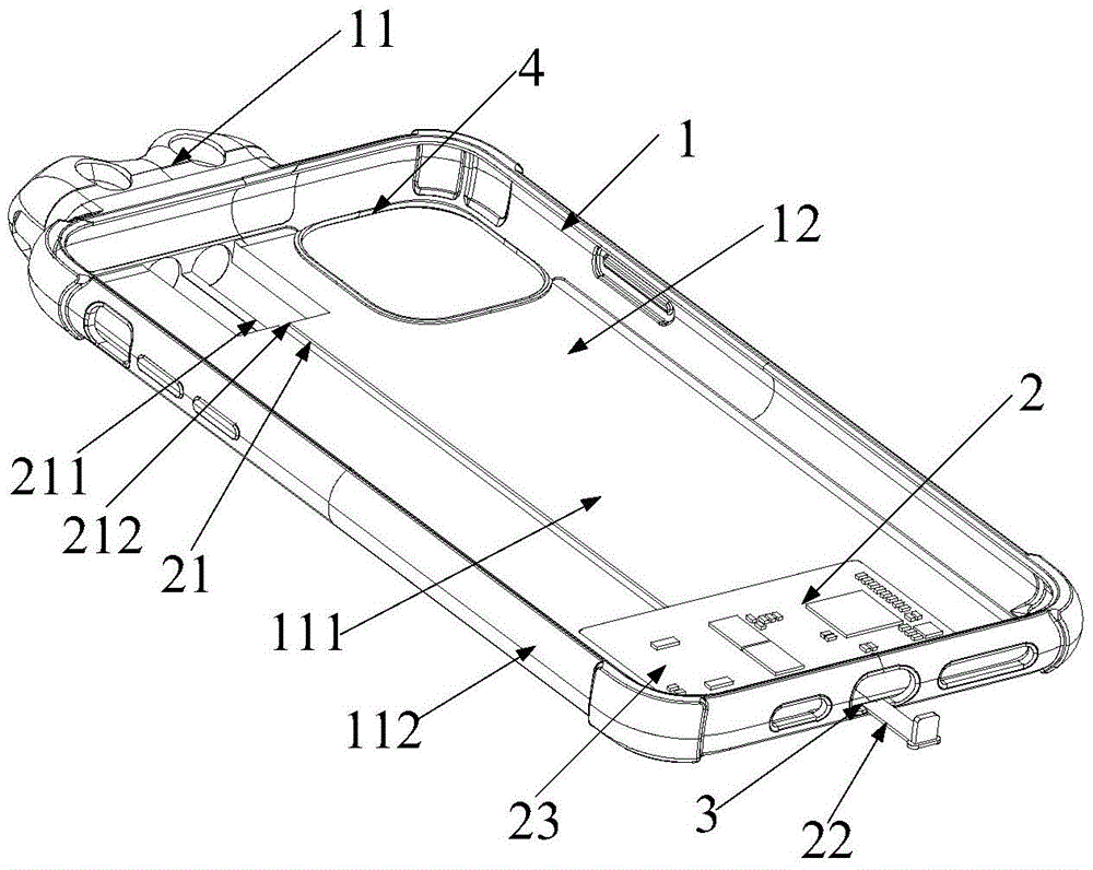
Fig. 1 is a schematic perspective view of a mobile phone case with an earphone charging function according to an embodiment of the present invention;
fig. 2 is a schematic structural diagram of a mobile phone case with an earphone according to an embodiment of the present invention in a disassembled state.
The reference numbers in the figures illustrate: 1 a housing part; 2. a circuit section; 11. an earphone accommodating space; 12. a mobile phone accommodating space; 21. a first connection terminal; 22. a second connection terminal; 23. a voltage stabilizing circuit; 211. a magnetic attraction component; 212. a detector; 111. a base plate; 112. a side plate; 113. a groove position; 3. a mobile phone charging port; 4. a camera hole.
Detailed Description
In order to facilitate understanding of the present invention, the present invention will be described more fully hereinafter with reference to the accompanying drawings. Preferred embodiments of the present invention are shown in the drawings. The invention may, however, be embodied in many different forms and should not be construed as limited to the embodiments set forth herein. Rather, these embodiments are provided so that this disclosure will be thorough and complete.
Unless defined otherwise, all technical and scientific terms used herein have the same meaning as commonly understood by one of ordinary skill in the art to which this invention belongs. The terminology used in the description of the invention herein is for the purpose of describing particular embodiments only and is not intended to be limiting of the invention. As used herein, the term "and/or" includes any and all combinations of one or more of the associated listed items.
Referring to fig. 1-2, as shown in the figures, an embodiment of the present invention provides a mobile phone shell with an earphone for charging, the mobile phone shell includes a shell portion 1 and a circuit portion 2 disposed in the shell portion 1, the shell portion 1 includes a bottom plate 111 and four side plates 112 disposed around the bottom plate 111, the bottom plate 111 and the four side plates 112 form a mobile phone accommodating space 12 for accommodating a mobile phone, an earphone accommodating space 11 for accommodating an earphone is disposed on the side plate 112 at the top of the bottom plate 111, a mobile phone charging port 3 is disposed on the side plate 112 at the bottom of the bottom plate 111, the circuit portion 2 includes a first connection terminal 21 and a second connection terminal 22, the first connection terminal 21 is disposed in the earphone accommodating space, the second connection terminal 22 is disposed in the mobile phone accommodating space and extends out of the shell portion 1, and is close to the mobile phone.
The bottom plate 111 is provided with a groove 113 for accommodating the circuit portion 2. Through the arrangement of the groove position, the line part can be kept consistent with the plane in the bottom plate after being placed into the groove part.
The circuit unit 2 is provided with a voltage regulator circuit 23 for stably supplying a voltage output from the mobile phone charging interface to the first connection terminal 21 via the second connection terminal 22. By using the voltage stabilizing circuit, the voltage output by the charging port end of the mobile phone can be stably supplied to the first wiring terminal through the second wiring terminal.
Wherein, the first connection terminal 21 is provided with a magnetic part 211 for adsorbing the earphone in the earphone receiving space 11.
The first connection terminal 21 is further provided with a detector 212 for detecting that the earphone is inserted, and the detector 212 is electrically connected to the circuit portion 2. Whether the earphone is placed into the earphone containing space is detected by the detector, when the earphone is placed into the earphone containing space, the electric quantity is output, and if the earphone is not detected in the earphone containing space, the electric quantity is not output.
Wherein, the bottom plate 111 is also provided with a camera hole 4. The camera head of the mobile phone is extended out through the camera hole.
The above combines the description figure right the utility model discloses a take cell-phone shell that earphone charges to carry out the detailed description, can understand, the utility model discloses a take cell-phone shell that earphone charges includes the cell-phone shell body, and the cell-phone shell body includes casing portion and sets up the circuit portion in casing portion, casing portion has cell-phone accommodation space and earphone and accomodates the space, and circuit portion includes first binding post and second binding post, and wherein in first binding post located earphone accommodation space, second binding post located in the cell-phone accommodation space and toward extending outside the casing portion. Through this kind of structural design, on the basis that protection cell-phone basic function can be realized to the cell-phone shell, further provide and accomodate the earphone and charge for the earphone function, a thing is multi-purpose, and it is more convenient to bring for the user.
The circuit part is also provided with a voltage stabilizing circuit, so that the voltage output by the mobile phone charging interface end can be stably supplied to the first wiring terminal from the second wiring terminal.
In addition, whether the earphone is inserted or not can be detected through the detector, and the control is only carried out on the electric quantity output when the earphone is inserted into the earphone accommodating space, so that the earphone is more intelligent and humanized.
The above only is the embodiment of the present invention, not limiting the patent scope of the present invention, all the equivalent structures or equivalent processes that are used in the specification and the attached drawings or directly or indirectly applied to other related technical fields are included in the patent protection scope of the present invention.