EP1505757A1 - Signal transmission method using antenna diversity and corresponding apparatus - Google Patents
Signal transmission method using antenna diversity and corresponding apparatus Download PDFInfo
- Publication number
- EP1505757A1 EP1505757A1 EP03425535A EP03425535A EP1505757A1 EP 1505757 A1 EP1505757 A1 EP 1505757A1 EP 03425535 A EP03425535 A EP 03425535A EP 03425535 A EP03425535 A EP 03425535A EP 1505757 A1 EP1505757 A1 EP 1505757A1
- Authority
- EP
- European Patent Office
- Prior art keywords
- antennas
- code
- pair
- spreading
- transmission via
- Prior art date
- Legal status (The legal status is an assumption and is not a legal conclusion. Google has not performed a legal analysis and makes no representation as to the accuracy of the status listed.)
- Granted
Links
- 238000000034 method Methods 0.000 title claims description 41
- 230000008054 signal transmission Effects 0.000 title description 2
- 230000005540 biological transmission Effects 0.000 claims abstract description 60
- 230000007480 spreading Effects 0.000 claims abstract description 48
- 230000006870 function Effects 0.000 claims description 6
- 238000010586 diagram Methods 0.000 description 5
- 230000003595 spectral effect Effects 0.000 description 3
- 230000021615 conjugation Effects 0.000 description 2
- 238000005562 fading Methods 0.000 description 2
- 230000006872 improvement Effects 0.000 description 2
- 238000010295 mobile communication Methods 0.000 description 2
- 230000011664 signaling Effects 0.000 description 2
- 108010003272 Hyaluronate lyase Proteins 0.000 description 1
- 230000009471 action Effects 0.000 description 1
- 230000004075 alteration Effects 0.000 description 1
- 238000013459 approach Methods 0.000 description 1
- 230000010267 cellular communication Effects 0.000 description 1
- 238000013461 design Methods 0.000 description 1
- 238000001514 detection method Methods 0.000 description 1
- 230000008030 elimination Effects 0.000 description 1
- 238000003379 elimination reaction Methods 0.000 description 1
- 238000001228 spectrum Methods 0.000 description 1
- 238000012360 testing method Methods 0.000 description 1
Images


Classifications
-
- H—ELECTRICITY
- H04—ELECTRIC COMMUNICATION TECHNIQUE
- H04L—TRANSMISSION OF DIGITAL INFORMATION, e.g. TELEGRAPHIC COMMUNICATION
- H04L1/00—Arrangements for detecting or preventing errors in the information received
- H04L1/004—Arrangements for detecting or preventing errors in the information received by using forward error control
- H04L1/0056—Systems characterized by the type of code used
- H04L1/0071—Use of interleaving
-
- H—ELECTRICITY
- H04—ELECTRIC COMMUNICATION TECHNIQUE
- H04L—TRANSMISSION OF DIGITAL INFORMATION, e.g. TELEGRAPHIC COMMUNICATION
- H04L1/00—Arrangements for detecting or preventing errors in the information received
- H04L1/02—Arrangements for detecting or preventing errors in the information received by diversity reception
- H04L1/06—Arrangements for detecting or preventing errors in the information received by diversity reception using space diversity
- H04L1/0618—Space-time coding
Definitions
- the present invention relates to techniques for signal transmission with antenna diversity and has been developed with particular attention paid to the possible application in the framework of telecommunications systems based upon the CDMA/3GPP (Code-division Multiple Access/Third Generation Partnership Project) standard in its various versions.
- CDMA/3GPP Code-division Multiple Access/Third Generation Partnership Project
- the 3GPP standard has defined both open-loop techniques, referred to, respectively, as STTD and TSTD, and closed-loop solutions, based upon beamforming techniques.
- the 3GPP standard contemplates the use of techniques based upon the use of two transmitting antennas set at the base stations (BTS) in combination with strategies for encoding the data transmitted by them.
- STC Space-time coding
- STTD Space-Time Transmit Diversity
- This scheme for data encoding which is applicable in the cellular-communication environment in so far as it functions also with just one antenna in reception, basically envisages that the sequence of the input bits (b 0 , b 1 , b 2 , b 3 ) is transmitted unaltered via a first antenna A and is, instead, subjected to a combined action of shuffling and of complementing that is such as to bring the sequence of four bits referred to previously to be sent for transmission via the second antenna in the form of the modified sequence (b 2 , b 3 , b 0 , b 1 ).
- this operation on the bits is mapped in a conjugation if the second bit (LSB) of the pair is complemented or in a conjugation with phase reversal (i.e., multiplication by -1) in the case where it is the first bit (MSB) of the pair that is complemented.
- LSB second bit
- MSB first bit
- V-BLAST Very BLAST
- the input signal x(t) is subjected, in a block designated by S, to the STTD-Rel. '99 coding procedure for each pair of antennas.
- This procedure uses the technique also known as Alamouti space-time block coding for generating two distinct signals x 1 and x 2 , which are to be subjected first to a multiplication by respective factors ⁇ and ⁇ in two multipliers in view of the supply to the antennas A a and A c .
- the same signals are once again subjected to a multiplication by two factors e j ⁇ and e j ⁇ , respectively, (in practice, a phase rotation is performed) in view of the supply to the antennas A b and A d .
- the diagram represented in Figure 2 uses the Alamouti technique, which is based upon the concept of transmitting the first branch with diversity according to the STTD scheme (s 1 , s 2 , ...) via a first antenna (A 1 ) and a replica subjected to phase rotation via the second antenna (A 2 ).
- the second branch with STTD diversity is transmitted in a similar way via the antennas A 3 and A 4 .
- FIG 3 illustrates schematically a technique referred to as "phase hopping”, which contemplates a phase rotation between the antennas and between the symbols according to a given sequence of values (by maintaining the phase constant for at least two consecutive symbols).
- the values indicated in braces refer to angles expressed in degrees.
- the purpose of the present invention is to provide an innovative solution for a diversity transmission scheme, which can be applied, for example, in a 3GPP UMTS system with more than two antennas, whilst maintaining, however, a complete compatibility with the currently standardized STTD scheme and, in general, with the transmission schemes that envisage using just two antennas in transmission.
- the invention also regards a corresponding transmitter, a corresponding receiver and also a computer product directly loadable into the memory of at least a digital computer and comprises software code portions for performing the steps of the method according to the invention when the computer product is run on a computer.
- the idea underlying the solution described herein contemplates inserting a further degree of freedom in the four-antenna system, separating the two pairs of antennas.
- the encoding on the two new antennas is partially changed by inserting an interleaving operation on 4 symbols - in this case (more in general on M symbols), whilst on the first two antennas the coding of the Release '99 standard is maintained to ensure compatibility in regard to systems that use the preceding versions of the standard.
- the Release '99 in question is in course of implementation, and the first services are at the moment served on limited areas by some operators. This enables a higher performance to be achieved both with respect to the current scheme and with respect to the scheme currently under discussion at the 3GPP, eliminating at the same time the need for implementing a phase-hopping technique on the antennas 2 and 4, this being an operation which of course presupposes the need to have available corresponding circuits, of which it is, instead, possible to do without by adopting the technique described herein.
- the solution described herein can, however, be extended also to a larger number of antennas. This can be obtained in a simple way both by varying the length of the interleaving on the additional pairs of antennas and by using another channelling/spreading code for these antennas, albeit maintaining unvaried the data rate.
- the implementation of such extensions on the basis of what is described herein constitutes for a person skilled in the sector a design task such as not to require a further detailed description herein.
- Said flow of data is sent to a block 10 capable of performing simultaneously a demultiplexing function (DMUX), together with a permutation function.
- DMUX demultiplexing function
- the module 10 splits the flow of input data between two lines designated, respectively, by 12 and 14.
- the data flow is sent without undergoing any variation, then to be transmitted to an STTD encoder 16 built in accordance with Release '99 of the 3GPP standard.
- the portion of the transmitter associated to the output line 14 of the block 10 is structurally similar, in the sense that this too comprises an STTD encoder designated by 22, with associated thereto at output two spreading modules 241, 242, which are to generate signals with a correspondingly widened spectrum. These signals are then supplied to the antennas Tx3 and Tx4 after addition of the respective pilot flows in two nodes designated by 261 and 262, respectively.
- the corresponding reception and decoding system contemplates the presence of a receiving antenna Rx, which is to receive, in a combined way, the signals coming from the transmission antennas Tx1, Tx2, Tx3 and Tx4.
- the signals received present, of course, the typical alterations induced by propagation in the transmission channel C, namely, the addition of noise N and the presence, in the signals received by the various transmission antennas, of phenomena of multipath fading that act in different ways in regard to each signal (this fact being, precisely, at the basis of the operation of diversity techniques).
- the signal coming from the receiving antenna Rx is sent to two matched filters 301 and 302, which are to perform the de-spreading operation, eliminating the two spreading codes c 1 and c 2 introduced in the transmission stage.
- the operation of the filters 301, 302 is based upon the formulae given in what follows, which have been developed just for the case of just one antenna in reception but can be extended (according to criteria that are evident to a person skilled in the art) to the case of more than one antenna in reception.
- the channel coefficients h ' / i and h " / i are assumed as being more or less constant (or estimated to be such) on two symbol time intervals.
- the corresponding estimation preferably implemented according to what is proposed by the 3G standard in Release '99 (but also already starting from Release 5), is performed according to known criteria in a channel-estimation block 32 that sends the corresponding coefficients to a linear receiver 34, which is to supply at output the symbols received S 1 , S 2 , S 3 , S 4 .
- the estimates in question constitute, precisely, the output signals indicated in the diagram of Figure 5 by S 1 S 2 S 3 S 4 .
- the decoding technique just described can be readily extended to the case of M generic pairs of transmitting antennas with M>2. Also in this case, the result can be obtained simply (and according to criteria that are evident for a person skilled in the art on the basis of the indications here provided) both by varying the interleaving length on the pairs of additional antennas, and by using another channelling/spreading code for them.
- the technique described herein moreover enables elimination from the base station of the phase-rotation function and the corresponding circuit (both at a hardware level and at the level of software components) by maintaining, at the same time, the so-called full rate; in other words, space-time coding does not reduce the transmission data rate.
- the demodulation technique described herein is maintained in the linear form, involving just de-spreading on two or more codes, which can be rendered perfectly serial and in line with a possible adoption of multiple-code transmission for a single client already envisaged by the standard.
Landscapes
- Engineering & Computer Science (AREA)
- Computer Networks & Wireless Communication (AREA)
- Signal Processing (AREA)
- Radio Transmission System (AREA)
- Mobile Radio Communication Systems (AREA)
Abstract
Description
- a different CDMA code - for example, a different OVSF (Orthogonal Variable Spreading Factor) code or equivalent, such as a different Walsh-Hadamard (WH) code - and the same scrambling code; or else
- the same CDMA code, but with a different scrambling code.
- Figures 1 to 3, which regard the prior art, have already been described previously;
- Figure 4 is a block diagram illustrating the transmission technique described herein; and
- Figure 5 illustrates the corresponding reception technique.
- whereas on the line 12 there is present the unaltered flow of data, just as it comes from the modulator at input to the block 10, on the line 14 there is present a data flow in which each set of four symbols is temporally swapped (and consequently subjected to shuffling or interleaving) by subsets, typically in pairs, causing the sequence (S1, S2, S3, S4) to become, at output from block 10, the sequence (S3, S4, S1, S2); and
- the spreading operation performed in the blocks 241 and 242 uses a second code c2, different from the code c1 used by the spreading blocks 181, 182; in other words, the two pairs of antennas Tx1, Tx2, on the one hand, and Tx3, Tx4, on the other hand, use different spreading codes, i.e., c1 and c2, respectively.
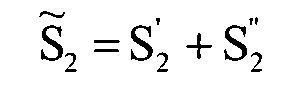
- h ' / i and h " / i represent the channel coefficients, and
- c1 and c2 are the two spreading codes used on the two pairs of antennas Tx1, Tx2 and Tx3, Tx4, respectively.



Claims (21)
- A method for transmitting, via a first pair of antennas (Tx1, Tx2) and at least one second pair of antennas (Tx3, Tx4), encoded digital symbols (S1 S2 S3 S4 ), which comprises the operations of:in which at least one between said respective code-division-multiple-access code (CDMA) and said respective spreading code (c2) used for the transmission via said at least one second pair of antennas (Tx3, Tx4) is different from the code-division-multiple-access code (CDMA) and from said spreading code (c1) used for the transmission via said first pair of antennas (Tx1, Tx2).organizing said encoded digital symbols in sets (S1 S2 S3 S4 ), the sets of symbols used for transmission via said at least one second pair of antennas (Tx3, Tx4) being re-ordered temporally (S3 S4 S1 S2 ) into subsets of symbols with respect to the encoded digital symbols used for the transmission via said first pair of antennas (Tx1, Tx2);using for transmission via said first pair of antennas (Tx1, Tx2) a signal that has undergone encoding with a code-division-multiple-access code (CDMA) subjected to spreading with a spreading code (c1); andusing for transmission via said at least one second pair of antennas (Tx3, Tx4) a signal subjected to encoding with a respective code-division-multiple-access code (CDMA) and subjected to spreading with a respective spreading code (c2);
- The method according to Claim 1, characterized in that said code-division-multiple-access code (CDMA) and said respective code-division-multiple-access code (CDMA) are OVSF codes.
- The method according to Claim 1 or Claim 2, characterized in that it comprises the operation of using for transmission via said first pair of antennas (Tx1, Tx2) and for transmission via said at least one second pair of antennas (Tx3, Tx4) the same code-division-multiple-access code (CDMA), using, instead, for transmission via said first pair of antennas (Tx1, Tx2) and for transmission via said at least one second pair of antennas (Tx3, Tx4) different spreading codes (c1, c2).
- The method according to any one of the preceding claims, characterized in that said encoded digital symbols are produced according to a modulation scheme chosen from the group consisting of M-PSK and M-QAM.
- The method according to any one of Claims 1 to 4, characterized in that said sets comprise four encoded digital symbols (S1 S2 S3 S4 ).
- The method according to any one of Claims 1 to 5, characterized in that said subsets of symbols are made up of pairs of symbols (S1 S2 ; S3 S4 ).
- The method according to Claim 1, characterized in that it comprises the operations of:in which at least one between said respective code-division-multiple-access code (CDMA) and said respective spreading codes (c2,..., cM) used for transmission via said plurality of second pairs of antennas is different from the code-division-multiple-access code (CDMA) and said spreading code (c1) used for transmission via said first pair of antennas (Tx1, Tx2).using, in addition to said first pair of antennas (Tx1, Tx2), a plurality of second pairs of antennas, the sets of symbols used for transmission via said plurality of second pairs of antennas being re-ordered temporally in subsets of symbols with respect to the encoded digital symbols used for transmission via said first pair of antennas (Tx1, Tx2); andusing, for transmission via said plurality of second pairs of antennas, signals subjected to encoding with respective code-division-multiple-access code (CDMA) and subjected to spreading with respective spreading codes (c2,...,cM );
- A transmitter for transmitting, via a first pair of antennas (Tx1, Tx2) and at least one second pair of antennas (Tx3, Tx4), encoded digital symbols (S1 S2 S3 S4 ), which comprises:at least one between said respective code-division-multiple-access code (CDMA) and said respective spreading code (c2) used for transmission via said at least one second pair of antennas (Tx3, Tx4) is different from the code-division-multiple-access code (CDMA) and said spreading code (c1) used for the transmission via said first pair of antennas (Tx1, Tx2).a processing module (10) configured for organizing said encoded digital symbols in sets (S1 S2 S3 S4 ), with the sets of symbols used for transmission via said at least one second pair of antennas (Tx3, Tx4) being re-ordered temporally (S3 S4 S1 S2 ) in subsets of symbols with respect to the encoded digital symbols used for transmission via said first pair of antennas (Tx1, Tx2);a first encoding (16) and spreading (181, 182) set capable of generating, for the transmission via said first pair of antennas (Tx1, Tx2), a signal subjected to encoding with a code-division-multiple-access code (CDMA) and subjected to spreading with a spreading code (c,); anda second encoding (22) and spreading (241, 242) set capable of generating, for the transmission via said at least one second pair of antennas (Tx3, Tx4), a signal subjected to a respective code-division-multiple-access code (CDMA) and subjected to spreading with a respective spreading code (c2), in which
- The transmitter according to Claim 8, characterized in that said code-division-multiple-access code (CDMA) and said respective code-division-multiple-access code (CDMA) are OVSF codes.
- The transmitter according to Claim 8 or Claim 9, characterized in that said first encoding (16) and spreading (181, 182) set and said second encoding (22) and spreading (241, 242) set are configured for using, for the transmission via said first pair of antennas (Tx1, Tx2) and for the transmission via said at least one second pair of antennas (Tx3, Tx4), the same code-division-multiple-access code (CDMA), and for using, instead, for the transmission via said first pair of antennas (Tx1, Tx2) and for the transmission via said at least one second pair of antennas (Tx3, Tx4), different spreading codes (c1,c2).
- The transmitter according to any one of the preceding Claims 8 to 10, characterized in that associated at its input it has a modulator chosen from the group consisting of an M-PSK modulator and an M-QAM modulator for generation of said encoded digital symbols.
- The transmitter according to any one of Claims 8 to 11, characterized in that said processing module (10) is configured for organizing said sets as sets that comprise four encoded digital symbols (S1 S2 S3 S4 ).
- The transmitter according to any one of Claims 8 to 12, characterized in that said processing module (10) is configured for organizing said subsets of symbols as pairs of symbols (S1 S2 ; S3 S4 ).
- The transmitter according to Claim 8, characterized in that:the transmitter is configured for using, in addition to said first pair of antennas (Tx1, Tx2), a plurality of second pairs of antennas;said processing module (10) is configured for re-ordering temporally in subsets the sets of symbols used for transmission via said plurality of second pairs of antennas with respect to the encoded digital symbols used for transmission via said first pair of antennas (Tx1, Tx2); andsaid second encoding (22) and spreading (241, 242) set is configured for generating, in view of transmission via said plurality of second pairs of antennas, signals encoded with respective code-division-multiple-access code (CDMA) subjected to spreading with respective spreading codes (c2,...,cM), in which at least one between said respective code-division-multiple-access code (CDMA) and said respective spreading codes (c2,...,cM) used for transmission via said plurality of second pairs of antennas is different from the code-division-multiple-access code (CDMA) and from said spreading code (c1) used for transmission via said first pair of antennas (Tx1, Tx2).
- A receiver for receiving, via at least one antenna (Rx), encoded digital symbols (S1 S2 S3 S4 ) transmitted via a first pair of antennas (Tx1, Tx2) and at least one second pair of antennas (Tx3, Tx4), in which:said receiver comprising at least one de-spreading device (301, 302) for eliminating from the signals received the presence of said spreading code (c1) and of said respective spreading code (c2) that are different from one another.said digital symbols are encoded in sets (S1 S2 S3 S4 ), the sets of symbols used for transmission via said at least one second pair of antennas (Tx3, Tx4) being re-ordered temporally (S3 S4 S1 S2 ) in subsets of symbols with respect to the encoded digital symbols used for transmission via said first pair of antennas (Tx1, Tx2);for transmission via said first pair of antennas (Tx1, Tx2) and for transmission via said at least one second pair of antennas (Tx3, Tx4), the same code-division-multiple-access code (CDMA) is used, while, for transmission via said first pair of antennas (Tx1, Tx2) and for transmission via said at least one second pair of antennas (Tx3, Tx4), there are used spreading codes (c1,c2), that are different from one another;
- The receiver according to Claim 15, characterized in that said at least one de-spreading device (301, 302) is a matched filter.
- The receiver according to Claim 15 or Claim 16, characterized in that said at least one de-spreading device comprises two de-spreading units (301, 302).
- The receiver according to any one of Claims 15 to 17, characterized in that it comprises a channel-estimating module (302) for deriving estimates of the transfer function of the channel comprised between said first pair of antennas (Tx1, Tx2) and at least one second pair of antennas (Tx3, Tx4), at one end, and said at least one receiving antenna (Rx), at the other end.
- The receiver according to Claim 18, characterized in that it comprises a linear receiver module (34) connected to said at least one de-spreading device (301, 302) for receiving said signals received by said at least one receiving antenna (Rx) cleared of the presence of said spreading code (c,) and of said respective spreading code (c2), and deriving therefrom estimates (


 ) according to channel coefficients (h ' / i and h " / i) produced by said channel-estimating module (32).
- The receiver according to Claim 15, characterized in that it is configured for using a plurality (M) of receiving antennas, operating on a linear combination of the signals received by a plurality of transmitting antennas.
- A computer product directly loadable into the memory of at least one digital computer and which comprises software code portions for performing the method according to any one of Claims 1 to 7, when the product is run on a computer.
Priority Applications (4)
| Application Number | Priority Date | Filing Date | Title |
|---|---|---|---|
| EP03425535A EP1505757B1 (en) | 2003-08-05 | 2003-08-05 | Signal transmission method using antenna diversity and corresponding apparatus |
| DE60322049T DE60322049D1 (en) | 2003-08-05 | 2003-08-05 | Signal transmission method using antenna diversity and corresponding device |
| US10/910,955 US7460581B2 (en) | 2003-08-05 | 2004-08-03 | Method for transmitting signals using antenna diversity, for instance in mobile communication systems, transmitter, receiver and computer program product therefor |
| US12/244,521 US7586979B2 (en) | 2003-08-05 | 2008-10-02 | Method for transmitting signals using antenna diversity, for instance in mobile communication systems, transmitter, receiver and computer program product therefor |
Applications Claiming Priority (1)
| Application Number | Priority Date | Filing Date | Title |
|---|---|---|---|
| EP03425535A EP1505757B1 (en) | 2003-08-05 | 2003-08-05 | Signal transmission method using antenna diversity and corresponding apparatus |
Publications (2)
| Publication Number | Publication Date |
|---|---|
| EP1505757A1 true EP1505757A1 (en) | 2005-02-09 |
| EP1505757B1 EP1505757B1 (en) | 2008-07-09 |
Family
ID=33547842
Family Applications (1)
| Application Number | Title | Priority Date | Filing Date |
|---|---|---|---|
| EP03425535A Expired - Lifetime EP1505757B1 (en) | 2003-08-05 | 2003-08-05 | Signal transmission method using antenna diversity and corresponding apparatus |
Country Status (3)
| Country | Link |
|---|---|
| US (2) | US7460581B2 (en) |
| EP (1) | EP1505757B1 (en) |
| DE (1) | DE60322049D1 (en) |
Families Citing this family (4)
| Publication number | Priority date | Publication date | Assignee | Title |
|---|---|---|---|---|
| KR100932260B1 (en) * | 2007-05-31 | 2009-12-16 | 한국전자통신연구원 | Decoding device and method for multiple input multiple output system |
| US8160513B2 (en) * | 2008-08-01 | 2012-04-17 | Qualcomm Incorporated | Methods and apparatus for implementing phase rotation at baseband frequency for transmit diversity |
| US8737502B2 (en) * | 2009-02-09 | 2014-05-27 | Qualcomm Incorporated | Multiplexing and coding schemes for multiple transmit antennas in a wireless communication system |
| US20230093484A1 (en) * | 2021-09-23 | 2023-03-23 | Apple Inc. | Systems and methods for de-correlating coded signals in dual port transmissions |
Citations (2)
| Publication number | Priority date | Publication date | Assignee | Title |
|---|---|---|---|---|
| WO2002043313A2 (en) * | 2000-11-22 | 2002-05-30 | Nortel Networks Limited | Space-time turbo trellis coding arrangement and method thereof |
| WO2002047278A2 (en) * | 2000-12-07 | 2002-06-13 | Interdigital Technology Corporation | Simple block space time transmit diversity using multiple spreading codes |
Family Cites Families (6)
| Publication number | Priority date | Publication date | Assignee | Title |
|---|---|---|---|---|
| JPH08195703A (en) * | 1995-01-17 | 1996-07-30 | Toshiba Corp | Wireless communication device |
| US6188736B1 (en) * | 1997-12-23 | 2001-02-13 | At&T Wireless Svcs. Inc. | Near-optimal low-complexity decoding of space-time codes for fixed wireless applications |
| RU2145152C1 (en) * | 1998-10-08 | 2000-01-27 | Гармонов Александр Васильевич | Method for orthogonal distributed transmission- reception of signal in cellular communication network using code channel division |
| KR100899735B1 (en) * | 2002-07-03 | 2009-05-27 | 삼성전자주식회사 | Adaptive Transmission Antenna Diversity System and Method in Mobile Communication Systems |
| KR100541285B1 (en) | 2002-10-02 | 2006-01-10 | 엘지전자 주식회사 | Signal Processing Method in Multiple Input / Output Communication System |
| KR100575929B1 (en) | 2003-05-29 | 2006-05-02 | 삼성전자주식회사 | Apparatus and method for transmitting and receiving data using multi-antenna diversity scheme in mobile communication system |
-
2003
- 2003-08-05 DE DE60322049T patent/DE60322049D1/en not_active Expired - Lifetime
- 2003-08-05 EP EP03425535A patent/EP1505757B1/en not_active Expired - Lifetime
-
2004
- 2004-08-03 US US10/910,955 patent/US7460581B2/en not_active Expired - Lifetime
-
2008
- 2008-10-02 US US12/244,521 patent/US7586979B2/en not_active Expired - Lifetime
Patent Citations (2)
| Publication number | Priority date | Publication date | Assignee | Title |
|---|---|---|---|---|
| WO2002043313A2 (en) * | 2000-11-22 | 2002-05-30 | Nortel Networks Limited | Space-time turbo trellis coding arrangement and method thereof |
| WO2002047278A2 (en) * | 2000-12-07 | 2002-06-13 | Interdigital Technology Corporation | Simple block space time transmit diversity using multiple spreading codes |
Also Published As
| Publication number | Publication date |
|---|---|
| US7586979B2 (en) | 2009-09-08 |
| US20050271121A1 (en) | 2005-12-08 |
| US20090041090A1 (en) | 2009-02-12 |
| DE60322049D1 (en) | 2008-08-21 |
| EP1505757B1 (en) | 2008-07-09 |
| US7460581B2 (en) | 2008-12-02 |
Similar Documents
| Publication | Publication Date | Title |
|---|---|---|
| CN100586050C (en) | Method and system for improving bandwidth efficiency in a multiple-input-multiple-output channel | |
| JP4328626B2 (en) | High rate transmit diversity transmission and reception | |
| KR100814155B1 (en) | Code division multiple access wireless system with time reversed space time block transmitter diversity encoding | |
| US6816557B2 (en) | Non-zero complex weighted space-time code for multiple antenna transmission | |
| US7623590B2 (en) | Diversity transmitter and diversity transmission method | |
| EP1594245B1 (en) | Apparatus and method for encoding/decoding space time block code in a mobile communication system using multiple input multiple output scheme | |
| Haas et al. | Increasing spectral efficiency by data multiplexing using antenna arrays | |
| WO2001076094A2 (en) | Space-time code for multiple antenna transmission | |
| JP2014239445A (en) | Multiple antenna transmission with variable diversity gain | |
| JP2004015828A (en) | Information bit modulation method, digital modulation system, digital demodulation system | |
| CN1360765A (en) | Transmit diversity transmitter and receiver for radio communications systems | |
| US7586979B2 (en) | Method for transmitting signals using antenna diversity, for instance in mobile communication systems, transmitter, receiver and computer program product therefor | |
| US20040081254A1 (en) | Transmitting digital signal | |
| US8223624B2 (en) | Method and apparatus for transmitting and receiving a data symbol stream | |
| Seo et al. | Comparative study of OFDM system with carrier interferometry code and STBC in flat fading channels | |
| Chen et al. | On a MIMO-based open wireless architecture: space-time complementary coding [Accepted from Open Call] | |
| EP2235848A1 (en) | Improvements in or relating to receive diversity systems | |
| KR20040062266A (en) | signal processing apparatus and method of multi input multi output communication system | |
| Garbo et al. | A linear chip-level model for multi-antenna space-time coded wideband CDMA reconfigurable receivers | |
| WO2001084739A2 (en) | Differential detection of signals using generalized orthogonal coding designs transmitted from multiple antennas |
Legal Events
| Date | Code | Title | Description |
|---|---|---|---|
| PUAI | Public reference made under article 153(3) epc to a published international application that has entered the european phase |
Free format text: ORIGINAL CODE: 0009012 |
|
| AK | Designated contracting states |
Kind code of ref document: A1 Designated state(s): AT BE BG CH CY CZ DE DK EE ES FI FR GB GR HU IE IT LI LU MC NL PT RO SE SI SK TR |
|
| AX | Request for extension of the european patent |
Extension state: AL LT LV MK |
|
| 17P | Request for examination filed |
Effective date: 20050413 |
|
| 17Q | First examination report despatched |
Effective date: 20050622 |
|
| AKX | Designation fees paid |
Designated state(s): DE FR GB IT |
|
| 17Q | First examination report despatched |
Effective date: 20050622 |
|
| GRAP | Despatch of communication of intention to grant a patent |
Free format text: ORIGINAL CODE: EPIDOSNIGR1 |
|
| GRAC | Information related to communication of intention to grant a patent modified |
Free format text: ORIGINAL CODE: EPIDOSCIGR1 |
|
| GRAS | Grant fee paid |
Free format text: ORIGINAL CODE: EPIDOSNIGR3 |
|
| GRAA | (expected) grant |
Free format text: ORIGINAL CODE: 0009210 |
|
| AK | Designated contracting states |
Kind code of ref document: B1 Designated state(s): DE FR GB IT |
|
| REG | Reference to a national code |
Ref country code: GB Ref legal event code: FG4D |
|
| REF | Corresponds to: |
Ref document number: 60322049 Country of ref document: DE Date of ref document: 20080821 Kind code of ref document: P |
|
| PLBE | No opposition filed within time limit |
Free format text: ORIGINAL CODE: 0009261 |
|
| STAA | Information on the status of an ep patent application or granted ep patent |
Free format text: STATUS: NO OPPOSITION FILED WITHIN TIME LIMIT |
|
| 26N | No opposition filed |
Effective date: 20090414 |
|
| GBPC | Gb: european patent ceased through non-payment of renewal fee |
Effective date: 20081009 |
|
| REG | Reference to a national code |
Ref country code: FR Ref legal event code: ST Effective date: 20090630 |
|
| PG25 | Lapsed in a contracting state [announced via postgrant information from national office to epo] |
Ref country code: IT Free format text: LAPSE BECAUSE OF FAILURE TO SUBMIT A TRANSLATION OF THE DESCRIPTION OR TO PAY THE FEE WITHIN THE PRESCRIBED TIME-LIMIT Effective date: 20080709 |
|
| PG25 | Lapsed in a contracting state [announced via postgrant information from national office to epo] |
Ref country code: FR Free format text: LAPSE BECAUSE OF NON-PAYMENT OF DUE FEES Effective date: 20080901 |
|
| PG25 | Lapsed in a contracting state [announced via postgrant information from national office to epo] |
Ref country code: GB Free format text: LAPSE BECAUSE OF NON-PAYMENT OF DUE FEES Effective date: 20081009 |
|
| REG | Reference to a national code |
Ref country code: DE Ref legal event code: R082 Ref document number: 60322049 Country of ref document: DE Representative=s name: SCHMITT-NILSON SCHRAUD WAIBEL WOHLFROM PATENTA, DE |
|
| PGFP | Annual fee paid to national office [announced via postgrant information from national office to epo] |
Ref country code: DE Payment date: 20220720 Year of fee payment: 20 |
|
| REG | Reference to a national code |
Ref country code: DE Ref legal event code: R071 Ref document number: 60322049 Country of ref document: DE |