EP1505678A1 - Fuel cell system - Google Patents
Fuel cell system Download PDFInfo
- Publication number
- EP1505678A1 EP1505678A1 EP04016139A EP04016139A EP1505678A1 EP 1505678 A1 EP1505678 A1 EP 1505678A1 EP 04016139 A EP04016139 A EP 04016139A EP 04016139 A EP04016139 A EP 04016139A EP 1505678 A1 EP1505678 A1 EP 1505678A1
- Authority
- EP
- European Patent Office
- Prior art keywords
- fuel cell
- pump
- temperature
- warm
- heater
- Prior art date
- Legal status (The legal status is an assumption and is not a legal conclusion. Google has not performed a legal analysis and makes no representation as to the accuracy of the status listed.)
- Withdrawn
Links
Images


Classifications
-
- H—ELECTRICITY
- H01—ELECTRIC ELEMENTS
- H01M—PROCESSES OR MEANS, e.g. BATTERIES, FOR THE DIRECT CONVERSION OF CHEMICAL ENERGY INTO ELECTRICAL ENERGY
- H01M8/00—Fuel cells; Manufacture thereof
- H01M8/04—Auxiliary arrangements, e.g. for control of pressure or for circulation of fluids
- H01M8/04298—Processes for controlling fuel cells or fuel cell systems
- H01M8/04313—Processes for controlling fuel cells or fuel cell systems characterised by the detection or assessment of variables; characterised by the detection or assessment of failure or abnormal function
- H01M8/0432—Temperature; Ambient temperature
- H01M8/04358—Temperature; Ambient temperature of the coolant
-
- H—ELECTRICITY
- H01—ELECTRIC ELEMENTS
- H01M—PROCESSES OR MEANS, e.g. BATTERIES, FOR THE DIRECT CONVERSION OF CHEMICAL ENERGY INTO ELECTRICAL ENERGY
- H01M8/00—Fuel cells; Manufacture thereof
- H01M8/04—Auxiliary arrangements, e.g. for control of pressure or for circulation of fluids
- H01M8/04223—Auxiliary arrangements, e.g. for control of pressure or for circulation of fluids during start-up or shut-down; Depolarisation or activation, e.g. purging; Means for short-circuiting defective fuel cells
- H01M8/04225—Auxiliary arrangements, e.g. for control of pressure or for circulation of fluids during start-up or shut-down; Depolarisation or activation, e.g. purging; Means for short-circuiting defective fuel cells during start-up
-
- H—ELECTRICITY
- H01—ELECTRIC ELEMENTS
- H01M—PROCESSES OR MEANS, e.g. BATTERIES, FOR THE DIRECT CONVERSION OF CHEMICAL ENERGY INTO ELECTRICAL ENERGY
- H01M8/00—Fuel cells; Manufacture thereof
- H01M8/04—Auxiliary arrangements, e.g. for control of pressure or for circulation of fluids
- H01M8/04298—Processes for controlling fuel cells or fuel cell systems
- H01M8/043—Processes for controlling fuel cells or fuel cell systems applied during specific periods
- H01M8/04302—Processes for controlling fuel cells or fuel cell systems applied during specific periods applied during start-up
-
- H—ELECTRICITY
- H01—ELECTRIC ELEMENTS
- H01M—PROCESSES OR MEANS, e.g. BATTERIES, FOR THE DIRECT CONVERSION OF CHEMICAL ENERGY INTO ELECTRICAL ENERGY
- H01M8/00—Fuel cells; Manufacture thereof
- H01M8/04—Auxiliary arrangements, e.g. for control of pressure or for circulation of fluids
- H01M8/04298—Processes for controlling fuel cells or fuel cell systems
- H01M8/04694—Processes for controlling fuel cells or fuel cell systems characterised by variables to be controlled
- H01M8/04701—Temperature
- H01M8/04738—Temperature of auxiliary devices, e.g. reformer, compressor, burner
-
- H—ELECTRICITY
- H01—ELECTRIC ELEMENTS
- H01M—PROCESSES OR MEANS, e.g. BATTERIES, FOR THE DIRECT CONVERSION OF CHEMICAL ENERGY INTO ELECTRICAL ENERGY
- H01M8/00—Fuel cells; Manufacture thereof
- H01M8/04—Auxiliary arrangements, e.g. for control of pressure or for circulation of fluids
- H01M8/04007—Auxiliary arrangements, e.g. for control of pressure or for circulation of fluids related to heat exchange
-
- H—ELECTRICITY
- H01—ELECTRIC ELEMENTS
- H01M—PROCESSES OR MEANS, e.g. BATTERIES, FOR THE DIRECT CONVERSION OF CHEMICAL ENERGY INTO ELECTRICAL ENERGY
- H01M8/00—Fuel cells; Manufacture thereof
- H01M8/04—Auxiliary arrangements, e.g. for control of pressure or for circulation of fluids
- H01M8/04082—Arrangements for control of reactant parameters, e.g. pressure or concentration
- H01M8/04089—Arrangements for control of reactant parameters, e.g. pressure or concentration of gaseous reactants
- H01M8/04119—Arrangements for control of reactant parameters, e.g. pressure or concentration of gaseous reactants with simultaneous supply or evacuation of electrolyte; Humidifying or dehumidifying
- H01M8/04156—Arrangements for control of reactant parameters, e.g. pressure or concentration of gaseous reactants with simultaneous supply or evacuation of electrolyte; Humidifying or dehumidifying with product water removal
-
- H—ELECTRICITY
- H01—ELECTRIC ELEMENTS
- H01M—PROCESSES OR MEANS, e.g. BATTERIES, FOR THE DIRECT CONVERSION OF CHEMICAL ENERGY INTO ELECTRICAL ENERGY
- H01M8/00—Fuel cells; Manufacture thereof
- H01M8/04—Auxiliary arrangements, e.g. for control of pressure or for circulation of fluids
- H01M8/04291—Arrangements for managing water in solid electrolyte fuel cell systems
-
- Y—GENERAL TAGGING OF NEW TECHNOLOGICAL DEVELOPMENTS; GENERAL TAGGING OF CROSS-SECTIONAL TECHNOLOGIES SPANNING OVER SEVERAL SECTIONS OF THE IPC; TECHNICAL SUBJECTS COVERED BY FORMER USPC CROSS-REFERENCE ART COLLECTIONS [XRACs] AND DIGESTS
- Y02—TECHNOLOGIES OR APPLICATIONS FOR MITIGATION OR ADAPTATION AGAINST CLIMATE CHANGE
- Y02E—REDUCTION OF GREENHOUSE GAS [GHG] EMISSIONS, RELATED TO ENERGY GENERATION, TRANSMISSION OR DISTRIBUTION
- Y02E60/00—Enabling technologies; Technologies with a potential or indirect contribution to GHG emissions mitigation
- Y02E60/30—Hydrogen technology
- Y02E60/50—Fuel cells
-
- Y—GENERAL TAGGING OF NEW TECHNOLOGICAL DEVELOPMENTS; GENERAL TAGGING OF CROSS-SECTIONAL TECHNOLOGIES SPANNING OVER SEVERAL SECTIONS OF THE IPC; TECHNICAL SUBJECTS COVERED BY FORMER USPC CROSS-REFERENCE ART COLLECTIONS [XRACs] AND DIGESTS
- Y10—TECHNICAL SUBJECTS COVERED BY FORMER USPC
- Y10T—TECHNICAL SUBJECTS COVERED BY FORMER US CLASSIFICATION
- Y10T428/00—Stock material or miscellaneous articles
- Y10T428/24—Structurally defined web or sheet [e.g., overall dimension, etc.]
- Y10T428/24008—Structurally defined web or sheet [e.g., overall dimension, etc.] including fastener for attaching to external surface
Definitions
- This invention relates to a fuel cell system which can be activated below freezing point with low power consumption.
- a fuel cell cooling device disclosed in Tokkai 2002-352835, published by the Japan Patent Office in 2002 controls the amount of water conveyed by a conveying pump and the amount of heat generated by a heater for preventing the freezing of cooling water on the basis of the temperature of the cooling water in the fuel cell and the differential pressure of the cooling water.
- the fuel cell cooling device comprises a water temperature sensor which detects the temperature of the cooling water and a differential pressure gauge which detects the differential pressure between the cooling water inlet and outlet of a fuel cell stack.
- the pump is located inside a pure water tank, and hence the size of the pure water tank increases, leading to a reduction in design freedom.
- the heater operates constantly within the pump in order to prevent freezing, and hence power consumption increases.
- An object of this invention is to provide a fuel cell system comprising a small pure water tank, in which only a small amount of power is required to start up the fuel cell.
- this invention provides a fuel cell system provided with a fuel cell which performs power generation using hydrogen and oxygen, a water tank which stores water to be supplied to the fuel cell, and a heating device which defrosts the water inside the tank during activation of the fuel cell.
- the fuel cell system comprises a switch which signals activation of the fuel cell; at least one temperature sensor which detects a temperature inside the water tank; a pump which conveys water from the water tank to the fuel cell; a heater which warms the pump; and a controller.
- the controller is programmed to read a start temperature from said at least one temperature sensor upon reception of a signal from the switch; calculate on the basis of the read start temperature a first warm-up period required for the water inside the water tank to reach a predetermined temperature greater than zero degrees centigrade; calculate on the basis of the read start temperature a second warm-up period required to defrost ice inside the pump using the heater; set a start time for warm-up of the pump using the heater on the basis of a difference between the first warm-up period and the second warm-up period; and control the heater to begin generating heat at the start time for warm-up of the pump.
- FIG. 1 is a schematic diagram of a fuel cell system of this invention.
- FIG. 2 is a front view of a pump.
- FIG. 3 is a sectional view of the pump along an A-A line of the pump in FIG. 2.
- FIG. 4 is a side view of a pump.
- FIG. 4A is a cross sectional view of a pump along pump axis.
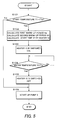
- FIG. 5 is a flowchart illustrating control executed by a controller.
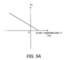
- FIG. 5A is a map for defining a relation between a predetermined temperature Tw and a start temperature T1.
- FIG. 6A is a map illustrating time variation in the temperature inside a pure water tank.
- FIG. 6B is a time chart illustrating time variation in the calorific value of a heater (when the heater is switched ON and OFF).
- FIG. 6C is a graph showing schematically the state of temperature increase in the pump 3.
- FIG. 7 is a map determining the relationship between a time period (tH) required for defrosting ice inside the pump using the heater, and a start temperature (T1) of the fuel cell system at the beginning of defrosting.
- a fuel cell system of this invention comprises a fuel cell 1, a pure water tank 2, a pump 3, a heater 12, a heat exchanger 4, a water temperature sensor 13, a temperature sensor 14, and a controller 15.
- the fuel cell 1 generates power by means of a reaction between hydrogen and oxygen, and supplies this power to the outside.
- the pure water tank 2 stores the pure water (water for humidifying oxygen gas or hydrogen gas) required for the reaction in the fuel cell 1.
- the pump 3 conveys pure water from the pure water tank 2 to the fuel cell 1, and circulates the pure water between the fuel cell 1 and the pure water tank 2.
- the heater 12 heats the pump 3 in order to defrost ice inside the pump 3 below freezing point.
- the heater 12 is preferably an electric heater.
- the heat exchanger 4 heats a heating medium for performing heat exchange with the pure water inside the pure water tank 2.
- the water temperature sensor 13 and temperature sensor 14 detect the temperature of the pure water tank.
- the controller 15 receives signals from the water temperature sensor 13 and temperature sensor 14, and controls the heater 12 in accordance with the temperature of the pure water tank 2.
- the fuel cell 1 comprises a pure water supply portion 6 having a water permeable membrane which supplies the pure water required to advance the hydrogen-oxygen reaction to the fuel cell 1.
- the pure water also functions as cooling water.
- the pure water is fed from the pure water tank 2 by the pump 3, passes through passages 7, 8, and is thus conveyed to the pure water supply portion 6. A part of the pure water is supplied to the fuel cell 1 by the pure water supply portion 6, whereupon the remaining pure water passes through a passage 9 and returns to the pure water tank 2.
- a pure water heating portion 10 is provided in the pure water tank 2 as a heating device which warms the pure water inside the tank upon start-up of the fuel cell.
- the heating medium heated by the heat exchanger 4 is circulated through the pure water heating portion 10 so as to defrost the frozen water.
- the frozen water may be defrosted using an electric heater as the heating device for warming the pure water inside the tank.
- the water temperature sensor 13 submerged in the pure water measures the water temperature inside the pure water tank 2 directly in the pure water tank 2.
- the temperature sensor 14 measures the temperature inside the pure water tank 2 (in particular, the air temperature directly above the pure water in the pure water tank 2). Since the temperature sensor 14 is not submerged in the pure water, the water temperature is measured by the temperature sensor 14 indirectly. When the pure water is frozen, the water temperature sensor 13 may malfunction, and hence at or below freezing point, the water temperature is preferably measured indirectly using the temperature sensor 14. As shown in FIG. 6A, the temperature of the pure water tank 2, detected by the temperature sensor 14, is raised by the heat generated in the pure water heating portion 10.
- a heat exchange passage 11 is provided in the heat exchanger 4.
- the heat exchange passage 11 performs heat exchange with high temperature gas that is generated by and recovered from a device, not shown in the drawing, inside the fuel cell system, and thus warms the heating medium inside the heat exchange passage 11.
- the heat exchange passage 11 is connected to the pure water heating portion 10 via passages 5, 16.
- a pump 17 circulates the heating medium through the passages.
- the pump 3 is provided on the outside of the pure water tank 2, and supplies pure water from the pure water tank 2 to the fuel cell 1.
- a heater 12 is attached to the pump 3 to defrost ice in the interior of the pump 3 when the pump 3 freezes.
- the heater 12 is rod-shaped, and the longitudinal direction thereof is substantially parallel to the axial direction of the pump.
- the heater 12 comprises a cylindrical head portion 12a and a core portion 12b which is coaxial with the head portion 12a and has a smaller diameter than the head portion 12a.
- a male screw 12c is cut into a part of the outer periphery of the core portion 12b.
- the pump 3 is an electrical motor pump, but not limited to this.
- the pump 3 is assembled by sandwiching a pump case 21 on both sides by a rear casing 22 and the front casing 20 (front cover).
- the rear casing 22 accommodates a cylindrical stator 41 of an electrical motor and the pump case 21 accommodates a cylindrical rotor 43 of the electrical motor rotor as shown in FIG. 4A.
- a female screw 3a is cut into the rear casing 22.
- the pump case 21 and front casing 20 each comprise a hole, which is coaxial with the female screw 3a of the rear casing 22, through which the heater 12 passes.
- the heater 12 is inserted from the front casing 20 side.
- the male screw 12c of the heater 12, which is screwed into the female screw 3a fixes the rear casing 22, pump case 21, and front casing 20 together tightly.
- the heat transfer coefficient of the pump 3 improves, and accumulations of frozen pure water inside the front casing 20 and rear casing 22, which cause freezing of the pump 3, can be defrosted swiftly. Moreover, heat is generated by the entire heater 12, and hence the front casing 20 and rear casing 22 can be warmed simultaneously even when the pump case 21 is formed from a thermal insulating material such as resin.
- the pump 3 may comprise a heater 18 in addition to the heater 12. At least one heater 18 is provided on the rear casing 22 of the pump 3. In so doing, frozen pure water in the pump 3 can be defrosted even more swiftly.
- the controller 15 performs control of the heater 12 and pump 3 in accordance with the water temperature inside the pure water tank 2, detected by the water temperature sensor 13, and the temperature of the pure water tank 2, detected by the temperature sensor 14.
- the controller 15 is a microcomputer-based controller.
- the controller 15 is constituted by a microcomputer comprising a central processing unit (CPU) which executes programs, read-only memory (ROM) which stores programs and data, random access memory (RAM) which stores calculation results of the CPU and obtained data temporarily, a timer which measures time, and an input/output interface (I / O interface).
- CPU central processing unit
- ROM read-only memory
- RAM random access memory
- I / O interface input/output interface
- the controller 15 When a start switch 19 is switched ON by an operator, the controller 15 receives a start signal from the start switch 19, and hence may begin the control routine. Further, when the start switch 19 is switched ON, the controller 15 starts up the pump 17 such that warm-up of the pure water tank 2 is begun by the pure water heating portion 10.
- a start temperature T1 of the pure water tank 2 is read as a start temperature of the fuel cell system by the temperature sensor 14, and a determination is made as to whether or not the start temperature T1 is lower than a predetermined temperature Tw.
- the predetermined temperature Tw is set to be slightly higher than zero degrees centigrade.
- the predetermined temperature Tw may be set, with reference to a map, to decrease according to the start temperature T1 as shown in FIG. 5A. Since warm-up of the pure water tank 2 begins at the time of the step S101, the start temperature T1 of the pure water tank 2 is substantially equal to the outside air temperature and the start temperature of the pump 3.
- the current time is set as an activation operation start time t0.
- the time t0 is preferably set to zero.
- step S 106 a pump switch is switched ON, and the pump 3 is started up.
- pure water from the pure water tank 2 is supplied to the fuel cell 1.
- a time period tw (first warm-up period) required for the pure water inside the pure water tank 2 to reach the predetermined temperature Tw is calculated on the basis of the start temperature T1 of the pure water tank 2, detected in the step S101, by referring to the map in FIG. 6A.
- the map in FIG. 6A shows time variation in the temperature inside the pure water tank.
- a time period tH (second warm-up period) required to defrost the ice inside the pump 3 using the heater 12 is determined on the basis of the detected start temperature T1 by referring to the map in FIG. 7.
- the map in FIG. 7 determines the relationship between the second warm-up period tH and the start temperature T1 of the pure water tank 2 (i.e. the outside air temperature).
- the start temperature T1 of the pure water tank 2 is substantially equal to a pump start temperature Tps at the beginning of pump defrosting, and hence the start temperature T1 of the pure water tank 2 can be used to determine the time period tH required to defrost the ice inside the pump using the heater.
- a start time t2 for warm-up of the pump 3 using the heater 12 is set on the basis of the difference Dt between the first warm-up period tw and the second warm-up period tH.
- the heater 12 may be switched ON simultaneously with the start of the activation operation.
- the maps in FIGs. 6A and 7 are determined in advance by experiment, and may be stored in the ROM of the controller 15.
- the warm-up period tw of the pure water tank 2 increases as the start temperature T1 falls. For example, referring to FIG. 6A, a lower start temperature T1' results in a longer warm-up period tw'.
- the warm-up period tH of the pump 3 also increases as the start temperature T1 falls. If the output of the heater 12 is small, the pure water inside the pure water tank 2 reaches the predetermined temperature Tw before warm-up of the pump 3 is complete. Hence the amount of heat generated by the heater 12 is set to be large enough such that the warm-up period tH of the pump 3 is shorter than the warm-up period tw of the pure water tank 2.
- a step S 103 the routine waits until the start time t2, and then, at the start time t2, the heater 12 is controlled to begin heat generation (the heater 12 is switched ON). Thus the heater 12 generates heat at a fixed calorific value (or a declared power). The fixed calorific value is determined in advance in consideration of the heat capacity and so on of the pump 3. Thus warm-up of the pump 3 is begun, and thereafter, the routine advances to a step S104.
- a water temperature T2 inside the pure water tank 2 is read from the water temperature sensor 13, and a determination is made as to whether or not the water temperature T2 is higher than the predetermined temperature Tw.
- Tw Tw
- the routine advances to a step S105.
- the step S 104 is repeated.
- the water temperature T2 is measured and read directly in the step S104.
- the water temperature T2 may be read indirectly from the temperature sensor 14 instead of being read from the water temperature sensor 13.
- a temperature (T1") which is read from the temperature sensor 14 at the current time may be used in place of the water temperature T2.
- the heater 12 is controlled to stop generating heat (the heater 12 is switched OFF) because the ice inside the pump 3 is defrosted.
- the routine then advances to the step S106, where the pump 3 is started up. Hence supply of the pure water inside the pure water tank 2 to the fuel cell 1 commences.
- the fuel cell or fuel cell system of this invention begins an activation operation (or a start-up operation).
- the temperature of the pure water tank 2 is the start temperature T1.
- the time period tw required for the temperature of the pure water tank 2 to reach the predetermined temperature Tw is calculated.
- the pure water in the pure water tank 2 is defrosted, and hence pure water can be supplied to the fuel cell 1.
- the time t2 at which the switch of the heater 12 is switched ON is determined on the basis of the time period tH required for the heater 12 to complete defrosting of the ice inside the pump 3.
- the switch of the heater 12 is switched ON, and warm-up of the pump 3 begins.
- the temperature Tp of the pump 3 rises as shown in FIG. 6C. Hence the ice inside the pump 3 begins to defrost.
- the switch of the heater 12 is switched OFF, and the switch of the pump 3 is switched ON. Henceforth, the pump 3 begins to supply pure water from the pure water tank 2 to the fuel cell 1.
- the pump 3 for conveying pure water from the pure water tank 2 to the fuel cell 1 is provided between the fuel cell 1 and the pure water tank 2.
- the size of the pure water tank 2 can be reduced, and the design freedom of the fuel cell system can be increased.
- the operating period tH of the heater 12 (warm-up period of the pump 3) required to defrost the ice inside the pump 3 is calculated on the basis of the start temperature T1 of the pure water tank 2. From the operating period tH, the warm-up start time t2 of the heater 12 is determined, and hence the heater 12 is able to defrost the ice inside the pump 3 with the minimum power consumption.
- the water temperature of the pure water tank 2 is detected by the water temperature sensor 13 in the pure water tank 2, and when the water temperature reaches a predetermined temperature, warm-up ends. Hence freezing of the pure water inside the passages can be prevented accurately.
- the pump case 21 is sandwiched between the front casing 20 and the rear casing 22, whereupon the pump case 21, front casing 20, and rear casing 22 are fixed together tightly. Hence in the pump 3, the heat of the heater 12 is transferred efficiently.
- the large-volume rear casing 22 can be warmed more quickly.
- the pure water tank 2 is preferably provided with the temperature sensor 14 which measures the start temperature of the pure water tank 2 as representative of the start temperature of the fuel cell system.
- a component other than the pure water tank 2 for example pump 3 may be provided with the temperature sensor 14 to measure the start temperature of the fuel cell system.
Landscapes
- Life Sciences & Earth Sciences (AREA)
- Engineering & Computer Science (AREA)
- Manufacturing & Machinery (AREA)
- Sustainable Development (AREA)
- Sustainable Energy (AREA)
- Chemical & Material Sciences (AREA)
- Chemical Kinetics & Catalysis (AREA)
- Electrochemistry (AREA)
- General Chemical & Material Sciences (AREA)
- Fuel Cell (AREA)
Abstract
Description
- This invention relates to a fuel cell system which can be activated below freezing point with low power consumption.
- A fuel cell cooling device disclosed in Tokkai 2002-352835, published by the Japan Patent Office in 2002, controls the amount of water conveyed by a conveying pump and the amount of heat generated by a heater for preventing the freezing of cooling water on the basis of the temperature of the cooling water in the fuel cell and the differential pressure of the cooling water. The fuel cell cooling device comprises a water temperature sensor which detects the temperature of the cooling water and a differential pressure gauge which detects the differential pressure between the cooling water inlet and outlet of a fuel cell stack.
- In this prior art, however, the pump is located inside a pure water tank, and hence the size of the pure water tank increases, leading to a reduction in design freedom. Moreover, the heater operates constantly within the pump in order to prevent freezing, and hence power consumption increases.
- An object of this invention is to provide a fuel cell system comprising a small pure water tank, in which only a small amount of power is required to start up the fuel cell.
- In order to achieve the above object, this invention provides a fuel cell system provided with a fuel cell which performs power generation using hydrogen and oxygen, a water tank which stores water to be supplied to the fuel cell, and a heating device which defrosts the water inside the tank during activation of the fuel cell. The fuel cell system comprises a switch which signals activation of the fuel cell; at least one temperature sensor which detects a temperature inside the water tank; a pump which conveys water from the water tank to the fuel cell; a heater which warms the pump; and a controller. The controller is programmed to read a start temperature from said at least one temperature sensor upon reception of a signal from the switch; calculate on the basis of the read start temperature a first warm-up period required for the water inside the water tank to reach a predetermined temperature greater than zero degrees centigrade; calculate on the basis of the read start temperature a second warm-up period required to defrost ice inside the pump using the heater; set a start time for warm-up of the pump using the heater on the basis of a difference between the first warm-up period and the second warm-up period; and control the heater to begin generating heat at the start time for warm-up of the pump.
- The details as well as other features and advantages of this invention are set forth in the remainder of the specification and are shown in the accompanying drawings.
- FIG. 1 is a schematic diagram of a fuel cell system of this invention.
- FIG. 2 is a front view of a pump.
- FIG. 3 is a sectional view of the pump along an A-A line of the pump in FIG. 2.
- FIG. 4 is a side view of a pump. FIG. 4A is a cross sectional view of a pump along pump axis.
- FIG. 5 is a flowchart illustrating control executed by a controller. FIG. 5A is a map for defining a relation between a predetermined temperature Tw and a start temperature T1.
- FIG. 6A is a map illustrating time variation in the temperature inside a pure water tank. FIG. 6B is a time chart illustrating time variation in the calorific value of a heater (when the heater is switched ON and OFF). FIG. 6C is a graph showing schematically the state of temperature increase in the
pump 3. - FIG. 7 is a map determining the relationship between a time period (tH) required for defrosting ice inside the pump using the heater, and a start temperature (T1) of the fuel cell system at the beginning of defrosting.
- Referring to FIG. 1, a fuel cell system of this invention comprises a
fuel cell 1, apure water tank 2, apump 3, aheater 12, aheat exchanger 4, awater temperature sensor 13, atemperature sensor 14, and acontroller 15. - The
fuel cell 1 generates power by means of a reaction between hydrogen and oxygen, and supplies this power to the outside. Thepure water tank 2 stores the pure water (water for humidifying oxygen gas or hydrogen gas) required for the reaction in thefuel cell 1. Thepump 3 conveys pure water from thepure water tank 2 to thefuel cell 1, and circulates the pure water between thefuel cell 1 and thepure water tank 2. Theheater 12 heats thepump 3 in order to defrost ice inside thepump 3 below freezing point. Theheater 12 is preferably an electric heater. The heat exchanger 4 heats a heating medium for performing heat exchange with the pure water inside thepure water tank 2. Thewater temperature sensor 13 andtemperature sensor 14 detect the temperature of the pure water tank. Thecontroller 15 receives signals from thewater temperature sensor 13 andtemperature sensor 14, and controls theheater 12 in accordance with the temperature of thepure water tank 2. - The
fuel cell 1 comprises a purewater supply portion 6 having a water permeable membrane which supplies the pure water required to advance the hydrogen-oxygen reaction to thefuel cell 1. The pure water also functions as cooling water. The pure water is fed from thepure water tank 2 by thepump 3, passes throughpassages water supply portion 6. A part of the pure water is supplied to thefuel cell 1 by the purewater supply portion 6, whereupon the remaining pure water passes through a passage 9 and returns to thepure water tank 2. - A pure
water heating portion 10 is provided in thepure water tank 2 as a heating device which warms the pure water inside the tank upon start-up of the fuel cell. When the pure water is frozen, the heating medium heated by theheat exchanger 4 is circulated through the purewater heating portion 10 so as to defrost the frozen water. The frozen water may be defrosted using an electric heater as the heating device for warming the pure water inside the tank. - The
water temperature sensor 13 submerged in the pure water measures the water temperature inside thepure water tank 2 directly in thepure water tank 2. Thetemperature sensor 14 measures the temperature inside the pure water tank 2 (in particular, the air temperature directly above the pure water in the pure water tank 2). Since thetemperature sensor 14 is not submerged in the pure water, the water temperature is measured by thetemperature sensor 14 indirectly. When the pure water is frozen, thewater temperature sensor 13 may malfunction, and hence at or below freezing point, the water temperature is preferably measured indirectly using thetemperature sensor 14. As shown in FIG. 6A, the temperature of thepure water tank 2, detected by thetemperature sensor 14, is raised by the heat generated in the purewater heating portion 10. - A
heat exchange passage 11 is provided in theheat exchanger 4. Theheat exchange passage 11 performs heat exchange with high temperature gas that is generated by and recovered from a device, not shown in the drawing, inside the fuel cell system, and thus warms the heating medium inside theheat exchange passage 11. Theheat exchange passage 11 is connected to the purewater heating portion 10 viapassages pump 17 circulates the heating medium through the passages. - The
pump 3 is provided on the outside of thepure water tank 2, and supplies pure water from thepure water tank 2 to thefuel cell 1. Aheater 12 is attached to thepump 3 to defrost ice in the interior of thepump 3 when thepump 3 freezes. - Referring to FIGs. 2, 3, the
pump 3 andheater 12 will be described. - Four
heaters 12 are attached to afront casing 20 of thepump 3 in four locations. Theheater 12 is rod-shaped, and the longitudinal direction thereof is substantially parallel to the axial direction of the pump. Referring to FIG. 3, theheater 12 comprises acylindrical head portion 12a and acore portion 12b which is coaxial with thehead portion 12a and has a smaller diameter than thehead portion 12a. Amale screw 12c is cut into a part of the outer periphery of thecore portion 12b. - The
pump 3 is an electrical motor pump, but not limited to this. Thepump 3 is assembled by sandwiching apump case 21 on both sides by arear casing 22 and the front casing 20 (front cover). Therear casing 22 accommodates acylindrical stator 41 of an electrical motor and thepump case 21 accommodates acylindrical rotor 43 of the electrical motor rotor as shown in FIG. 4A. Afemale screw 3a is cut into therear casing 22. Thepump case 21 andfront casing 20 each comprise a hole, which is coaxial with thefemale screw 3a of therear casing 22, through which theheater 12 passes. Theheater 12 is inserted from thefront casing 20 side. Themale screw 12c of theheater 12, which is screwed into thefemale screw 3a, fixes therear casing 22,pump case 21, andfront casing 20 together tightly. - Thus the heat transfer coefficient of the
pump 3 improves, and accumulations of frozen pure water inside thefront casing 20 andrear casing 22, which cause freezing of thepump 3, can be defrosted swiftly. Moreover, heat is generated by theentire heater 12, and hence thefront casing 20 andrear casing 22 can be warmed simultaneously even when thepump case 21 is formed from a thermal insulating material such as resin. - Referring to FIG. 4, the
pump 3 may comprise aheater 18 in addition to theheater 12. At least oneheater 18 is provided on therear casing 22 of thepump 3. In so doing, frozen pure water in thepump 3 can be defrosted even more swiftly. - The
controller 15 performs control of theheater 12 andpump 3 in accordance with the water temperature inside thepure water tank 2, detected by thewater temperature sensor 13, and the temperature of thepure water tank 2, detected by thetemperature sensor 14. - The
controller 15 is a microcomputer-based controller. Thecontroller 15 is constituted by a microcomputer comprising a central processing unit (CPU) which executes programs, read-only memory (ROM) which stores programs and data, random access memory (RAM) which stores calculation results of the CPU and obtained data temporarily, a timer which measures time, and an input/output interface (I / O interface). - Next, referring to the flowchart in FIG. 5, an activation control routine (program) executed by the
controller 15 will be described. - When a
start switch 19 is switched ON by an operator, thecontroller 15 receives a start signal from thestart switch 19, and hence may begin the control routine. Further, when thestart switch 19 is switched ON, thecontroller 15 starts up thepump 17 such that warm-up of thepure water tank 2 is begun by the purewater heating portion 10. - In a step S101, a start temperature T1 of the
pure water tank 2 is read as a start temperature of the fuel cell system by thetemperature sensor 14, and a determination is made as to whether or not the start temperature T1 is lower than a predetermined temperature Tw. The predetermined temperature Tw is set to be slightly higher than zero degrees centigrade. The predetermined temperature Tw may be set, with reference to a map, to decrease according to the start temperature T1 as shown in FIG. 5A. Since warm-up of thepure water tank 2 begins at the time of the step S101, the start temperature T1 of thepure water tank 2 is substantially equal to the outside air temperature and the start temperature of thepump 3. When the start temperature T1 (or outside air temperature) is lower than the predetermined temperature Tw, there is a possibility that thepump 3 is frozen, and also that pure water has frozen inside thepump 3 and passages 7-9. When T1 is equal to or higher than Tw (T1 ≥ Tw), it is determined that thepump 3 is defrosted and that pure water supplied from thepure water tank 2 has not frozen inside thepump 3 and passages 7-9, and hence the routine advances to a step S106. - Also in the step S101, the current time is set as an activation operation start time t0. Normally, the time t0 is preferably set to zero.
- In the step S 106, a pump switch is switched ON, and the
pump 3 is started up. Thus pure water from thepure water tank 2 is supplied to thefuel cell 1. - When T1 is lower than Tw (T1 < Tw), it is determined that the
pump 3 is frozen and that pure water supplied from thepure water tank 2 has frozen inside thepump 3 and passages 7-9, and hence the routine advances to a step S102. - In the step S102, a time period tw (first warm-up period) required for the pure water inside the
pure water tank 2 to reach the predetermined temperature Tw is calculated on the basis of the start temperature T1 of thepure water tank 2, detected in the step S101, by referring to the map in FIG. 6A. The map in FIG. 6A shows time variation in the temperature inside the pure water tank. - Further, in the step S102, a time period tH (second warm-up period) required to defrost the ice inside the
pump 3 using theheater 12 is determined on the basis of the detected start temperature T1 by referring to the map in FIG. 7. The map in FIG. 7 determines the relationship between the second warm-up period tH and the start temperature T1 of the pure water tank 2 (i.e. the outside air temperature). The start temperature T1 of thepure water tank 2 is substantially equal to a pump start temperature Tps at the beginning of pump defrosting, and hence the start temperature T1 of thepure water tank 2 can be used to determine the time period tH required to defrost the ice inside the pump using the heater. Finally in the step S102, a start time t2 for warm-up of thepump 3 using theheater 12 is set on the basis of the difference Dt between the first warm-up period tw and the second warm-up period tH. The start time t2 is the sum of the activation operation start time t0 (the time at which the start temperature T1 is read in the step S101) and the difference Dt between the time period tH and the time period tw (t2=t0+Dt=t0+tw-tH). - When T1=0°C, the time period tw cannot be determined univocally from the start temperature T1 in the map in FIG. 6A, and hence the start time t2 for warm-up of the
pump 3 may be set to t0 without calculating the time period tw and the time period tH (Dt=0). In other words, theheater 12 may be switched ON simultaneously with the start of the activation operation. - The maps in FIGs. 6A and 7 are determined in advance by experiment, and may be stored in the ROM of the
controller 15. The warm-up period tw of thepure water tank 2 increases as the start temperature T1 falls. For example, referring to FIG. 6A, a lower start temperature T1' results in a longer warm-up period tw'. The warm-up period tH of thepump 3 also increases as the start temperature T1 falls.
If the output of theheater 12 is small, the pure water inside thepure water tank 2 reaches the predetermined temperature Tw before warm-up of thepump 3 is complete. Hence the amount of heat generated by theheater 12 is set to be large enough such that the warm-up period tH of thepump 3 is shorter than the warm-up period tw of thepure water tank 2. - In a step S 103, the routine waits until the start time t2, and then, at the start time t2, the
heater 12 is controlled to begin heat generation (theheater 12 is switched ON). Thus theheater 12 generates heat at a fixed calorific value (or a declared power). The fixed calorific value is determined in advance in consideration of the heat capacity and so on of thepump 3. Thus warm-up of thepump 3 is begun, and thereafter, the routine advances to a step S104. - In the step S104, a water temperature T2 inside the
pure water tank 2 is read from thewater temperature sensor 13, and a determination is made as to whether or not the water temperature T2 is higher than the predetermined temperature Tw. When the water temperature T2 is higher than Tw (T2 ≥ Tw), it is determined that the ice inside thepump 3 is defrosted, and that the pure water in the passages has ceased to freeze during the supply of pure water to thefuel cell 1. Hence the routine advances to a step S105. When the water temperature T2 is lower than Tw (T2 < Tw), the step S 104 is repeated. - For the sake of accuracy, the water temperature T2 is measured and read directly in the step S104. However, the water temperature T2 may be read indirectly from the
temperature sensor 14 instead of being read from thewater temperature sensor 13. In other words, a temperature (T1") which is read from thetemperature sensor 14 at the current time may be used in place of the water temperature T2. - In the step S105, the
heater 12 is controlled to stop generating heat (theheater 12 is switched OFF) because the ice inside thepump 3 is defrosted. - The routine then advances to the step S106, where the
pump 3 is started up. Hence supply of the pure water inside thepure water tank 2 to thefuel cell 1 commences. - Referring to the time chart in FIG. 6B, an operation of the
heater 12 will be described. - At the time t0, the fuel cell or fuel cell system of this invention begins an activation operation (or a start-up operation). At this time, the temperature of the
pure water tank 2 is the start temperature T1. On the basis of the start temperature T1, the time period tw required for the temperature of thepure water tank 2 to reach the predetermined temperature Tw is calculated. At or above the predetermined temperature Tw, the pure water in thepure water tank 2 is defrosted, and hence pure water can be supplied to thefuel cell 1. The time t2 at which the switch of theheater 12 is switched ON is determined on the basis of the time period tH required for theheater 12 to complete defrosting of the ice inside thepump 3. - At the time t2, the switch of the
heater 12 is switched ON, and warm-up of thepump 3 begins. The temperature Tp of thepump 3 rises as shown in FIG. 6C. Hence the ice inside thepump 3 begins to defrost. - When the time period tw has elapsed and the water temperature of the
pure water tank 2 has reached Tw, the switch of theheater 12 is switched OFF, and the switch of thepump 3 is switched ON. Henceforth, thepump 3 begins to supply pure water from thepure water tank 2 to thefuel cell 1. - Next, effects of the embodiment of this invention will be described.
- The
pump 3 for conveying pure water from thepure water tank 2 to thefuel cell 1 is provided between thefuel cell 1 and thepure water tank 2. Thus the size of thepure water tank 2 can be reduced, and the design freedom of the fuel cell system can be increased. - When the fuel cell is activated below freezing point, the operating period tH of the heater 12 (warm-up period of the pump 3) required to defrost the ice inside the
pump 3 is calculated on the basis of the start temperature T1 of thepure water tank 2. From the operating period tH, the warm-up start time t2 of theheater 12 is determined, and hence theheater 12 is able to defrost the ice inside thepump 3 with the minimum power consumption. - The water temperature of the
pure water tank 2 is detected by thewater temperature sensor 13 in thepure water tank 2, and when the water temperature reaches a predetermined temperature, warm-up ends. Hence freezing of the pure water inside the passages can be prevented accurately. - In the
pump 3, thepump case 21 is sandwiched between thefront casing 20 and therear casing 22, whereupon thepump case 21,front casing 20, andrear casing 22 are fixed together tightly. Hence in thepump 3, the heat of theheater 12 is transferred efficiently. By providing aheater 18 on therear casing 22 in addition to theheater 12, the large-volumerear casing 22 can be warmed more quickly. - In the above embodiment, the
pure water tank 2 is preferably provided with thetemperature sensor 14 which measures the start temperature of thepure water tank 2 as representative of the start temperature of the fuel cell system. However, a component other than the pure water tank 2 (for example pump 3) may be provided with thetemperature sensor 14 to measure the start temperature of the fuel cell system. - Although the invention has been described above by reference to a certain embodiment of the invention, the invention is not limited to the embodiment described above. Modifications and variations of the embodiment described above will occur to those skilled in the art, in light of the above teachings. The scope of the invention is defined with reference to the following claims.
- The entire contents of Japanese Patent Application P2003-202488 (filed July 28, 2003) are incorporated herein by reference.
Claims (11)
- A fuel cell system provided with a fuel cell (1) which performs power generation using hydrogen and oxygen, a water tank (2) which stores water to be supplied to the fuel cell, and a heating device (10) which defrosts the water inside the tank during activation of the fuel cell, the fuel cell system comprising:a switch (19) which signals activation of the fuel cell;at least one temperature sensor (13, 14) which detects a temperature inside the water tank;a pump (3) which conveys water from the water tank to the fuel cell;a heater (12) which warms the pump; anda controller (15) programmed to:read a start temperature from said at least one temperature sensor (13, 14) upon reception of a signal from the switch (19);calculate on the basis of the read start temperature a first warm-up period (tw) required for the water inside the water tank (2) to reach a predetermined temperature (Tw) greater than zero degrees centigrade;calculate on the basis of the read start temperature a second warm-up period (tH) required to defrost ice inside the pump (3) using the heater;set a start time (t2) for warm-up of the pump (3) using the heater on the basis of a difference (Dt) between the first warm-up period (tw) and the second warm-up period (tH); andcontrol the heater to begin generating heat at the start time (t2) for warm-up of the pump (3).
- The fuel cell system as defined in Claim 1, wherein the start time (t2) for warm-up of the pump (3) is retarded from a time (t0) at which the controller (15) receives the signal from the switch (19) by the difference (Dt) between the first warm-up period (tw) and the second warm-up period (tH).
- The fuel cell system as defined in Claim 1, wherein the controller (15) comprises a first map which illustrates time variation in the temperature inside the water tank, and a second map which determines a relationship between the second warm-up period and the start temperature, and
the controller (15) is further programmed to:calculate the first warm-up period (tw) by referring to the first map; andcalculate the second warm-up period (tH) by referring to the second map. - The fuel cell system as defined in Claim 1, wherein the controller (15) is further programmed to:read a water tank temperature from said at least one temperature sensor (13, 14) after the heater has begun to generate heat;determine whether or not the read water tank temperature is higher than the predetermined temperature (Tw); andcontrol the heater to stop generating heat when the read water tank temperature is higher than the predetermined temperature (Tw).
- The fuel cell system as defined in Claim 4, wherein the controller (15) is further programmed to start up the pump (3) after controlling the heater to stop generating heat.
- The fuel cell system as defined in Claim 1, wherein the controller (15) is further programmed to:determine whether or not the start temperature read upon reception of the signal from the switch (19) is lower than the predetermined temperature (Tw);start up the pump (3) when the start temperature is equal to or higher than the predetermined temperature (Tw); andstart up the pump (3) after the heater has generated heat when the start temperature is lower than the predetermined temperature (Tw).
- The fuel cell system as defined in Claim 1,
wherein the pump comprises a front casing, a rear casing, and a pump case sandwiched therebetween,
the rear casing is provided with a female screw,
a part of the outer periphery of the heater is provided with a male screw, and
the front casing and the rear casing are joined by screwing the male screw into the female screw. - The fuel cell system as defined in Claim 7, wherein the pump comprises another heater on the rear casing.
- The fuel cell system as defined in Claim 1, wherein said at least one temperature sensor (13, 14) includes a temperature sensor submerged in the water inside the water tank (2) to directly detect a water temperature, and a temperature sensor not submerged in the water inside the water tank (2).
- A fuel cell system provided with a fuel cell (1) which performs power generation using hydrogen and oxygen, a water tank (2) which stores water to be supplied to the fuel cell, and a heating device (10) which defrosts the water inside the tank during activation of the fuel cell, the fuel cell system comprising:signal means (19) for signaling activation of the fuel cell;detecting means (13, 14) for detecting a temperature inside the water tank;pump means (3) for conveying water from the water tank to the fuel cell;heating means (12) for warming the pump; andreading means for reading a start temperature from said detecting means (13, 14) upon reception of a signal from signal means (19);calculating means for calculating on the basis of the read start temperature a first warm-up period (tw) required for the water inside the water tank (2) to reach a predetermined temperature (Tw) greater than zero degrees centigrade;calculating means for calculating on the basis of the read start temperature a second warm-up period (tH) required to defrost ice inside the pump (3) using the heater;setting means for setting a start time (t2) for warm-up of the pump (3) using the heater on the basis of a difference (Dt) between the first warm-up period (tw) and the second warm-up period (tH); andcontrol means for controlling the heater to begin generating heat at the start time (t2) for warm-up of the pump (3).
- A start-up control method for a fuel cell system, the fuel cell system being provided with a fuel cell (1) which performs power generation using hydrogen and oxygen, a water tank (2) which stores water to be supplied to the fuel cell, a heating device (10) which defrosts the water inside the tank during activation of the fuel cell, a switch (19) which signals activation of the fuel cell, at least one temperature sensor (13, 14) which detects a temperature inside the water tank, a pump (3) which conveys water from the water tank to the fuel cell, and a heater (12) which warms the pump, the start-up control method comprising the steps of:reading a start temperature from said at least one temperature sensor (13, 14) upon reception of a signal from the switch (19);calculating on the basis of the read start temperature a first warm-up period (tw) required for the water inside the water tank (2) to reach a predetermined temperature (Tw) greater than zero degrees centigrade;calculating on the basis of the read start temperature a second warm-up period (tH) required to defrost ice inside the pump (3) using the heater;setting a start time (t2) for warm-up of the pump (3) using the heater on the basis of a difference (Dt) between the first warm-up period (tw) and the second warm-up period (tH); andcontrolling the heater to begin generating heat at the start time (t2) for warm-up of the pump (3).
Applications Claiming Priority (2)
| Application Number | Priority Date | Filing Date | Title |
|---|---|---|---|
| JP2003202488A JP2005044605A (en) | 2003-07-28 | 2003-07-28 | Fuel cell system |
| JP2003202488 | 2003-07-28 |
Publications (1)
| Publication Number | Publication Date |
|---|---|
| EP1505678A1 true EP1505678A1 (en) | 2005-02-09 |
Family
ID=33549880
Family Applications (1)
| Application Number | Title | Priority Date | Filing Date |
|---|---|---|---|
| EP04016139A Withdrawn EP1505678A1 (en) | 2003-07-28 | 2004-07-08 | Fuel cell system |
Country Status (3)
| Country | Link |
|---|---|
| US (1) | US7381486B2 (en) |
| EP (1) | EP1505678A1 (en) |
| JP (1) | JP2005044605A (en) |
Cited By (3)
| Publication number | Priority date | Publication date | Assignee | Title |
|---|---|---|---|---|
| WO2008127354A2 (en) * | 2006-10-04 | 2008-10-23 | Bdf Ip Holdings Ltd. | System and method for fuel cell load cycling for fast warm-up of a fuel cell stack |
| WO2008141712A1 (en) * | 2007-05-18 | 2008-11-27 | Daimler Ag | Heating device for condensate trap |
| CN102237538A (en) * | 2010-04-05 | 2011-11-09 | 通用汽车环球科技运作有限责任公司 | Method to detect no coolant flow in a fuel cell system |
Families Citing this family (8)
| Publication number | Priority date | Publication date | Assignee | Title |
|---|---|---|---|---|
| CN100570230C (en) * | 2005-02-18 | 2009-12-16 | 松下电器产业株式会社 | Cogeneration system |
| US20090114733A1 (en) * | 2007-11-07 | 2009-05-07 | Matusinec Robert D | Hydrogen fired heat exchanger |
| KR101047414B1 (en) * | 2008-02-15 | 2011-07-08 | 기아자동차주식회사 | Humidifier for fuel cell stack using injector |
| GB0814458D0 (en) * | 2008-08-07 | 2008-09-10 | Nanoco Technologies Ltd | Surface functionalised nanoparticles |
| JP2011174816A (en) * | 2010-02-24 | 2011-09-08 | Sony Corp | Electronic apparatus and method of controlling electronic apparatus |
| EP2787598B1 (en) * | 2011-11-28 | 2018-04-25 | Kyocera Corporation | Power control device, power control system, and power control method |
| JP5774128B2 (en) * | 2011-12-16 | 2015-09-02 | 三菱電機株式会社 | Air conditioner |
| GB2565141B (en) | 2017-08-04 | 2021-09-22 | Intelligent Energy Ltd | Devices and methods for controlling a fluid module |
Citations (2)
| Publication number | Priority date | Publication date | Assignee | Title |
|---|---|---|---|---|
| EP1265304A2 (en) * | 2001-05-28 | 2002-12-11 | Nissan Motor Co., Ltd. | Cooling water recirculation in a fuel cell power plant |
| WO2003073547A2 (en) * | 2002-02-27 | 2003-09-04 | Nissan Motor Co., Ltd. | Freeze-protected fuel cell system and method of protecting a fuel cell from freezing |
Family Cites Families (1)
| Publication number | Priority date | Publication date | Assignee | Title |
|---|---|---|---|---|
| JPH08263148A (en) * | 1995-03-20 | 1996-10-11 | Nissin Electric Co Ltd | Water temperature regulating device for water tank |
-
2003
- 2003-07-28 JP JP2003202488A patent/JP2005044605A/en not_active Withdrawn
-
2004
- 2004-07-08 EP EP04016139A patent/EP1505678A1/en not_active Withdrawn
- 2004-07-20 US US10/893,868 patent/US7381486B2/en not_active Expired - Fee Related
Patent Citations (2)
| Publication number | Priority date | Publication date | Assignee | Title |
|---|---|---|---|---|
| EP1265304A2 (en) * | 2001-05-28 | 2002-12-11 | Nissan Motor Co., Ltd. | Cooling water recirculation in a fuel cell power plant |
| WO2003073547A2 (en) * | 2002-02-27 | 2003-09-04 | Nissan Motor Co., Ltd. | Freeze-protected fuel cell system and method of protecting a fuel cell from freezing |
Cited By (5)
| Publication number | Priority date | Publication date | Assignee | Title |
|---|---|---|---|---|
| WO2008127354A2 (en) * | 2006-10-04 | 2008-10-23 | Bdf Ip Holdings Ltd. | System and method for fuel cell load cycling for fast warm-up of a fuel cell stack |
| WO2008127354A3 (en) * | 2006-10-04 | 2008-12-04 | Bdf Ip Holdings Ltd | System and method for fuel cell load cycling for fast warm-up of a fuel cell stack |
| WO2008141712A1 (en) * | 2007-05-18 | 2008-11-27 | Daimler Ag | Heating device for condensate trap |
| CN102237538A (en) * | 2010-04-05 | 2011-11-09 | 通用汽车环球科技运作有限责任公司 | Method to detect no coolant flow in a fuel cell system |
| CN102237538B (en) * | 2010-04-05 | 2014-04-02 | 通用汽车环球科技运作有限责任公司 | Method to detect no coolant flow in a fuel cell system |
Also Published As
| Publication number | Publication date |
|---|---|
| US7381486B2 (en) | 2008-06-03 |
| JP2005044605A (en) | 2005-02-17 |
| US20050026013A1 (en) | 2005-02-03 |
Similar Documents
| Publication | Publication Date | Title |
|---|---|---|
| US7381486B2 (en) | Fuel cell system | |
| EP1520312B1 (en) | Fuel cell power plant | |
| US7154068B2 (en) | Method and system for a vehicle battery temperature control | |
| JP3801111B2 (en) | Fuel cell system | |
| EP1712780B1 (en) | Internal combustion engine with heat accumulating device and method of controlling same | |
| US7451747B2 (en) | Heating system for liquefied gas fuel supply apparatus and fuel supply appartus for liquefied gas engine | |
| US9099700B2 (en) | Fuel cell system and warming up completion determining method for the same | |
| CN107726633B (en) | Heat pump water heater and anti-freezing control method and device thereof | |
| JP2006179198A (en) | Fuel cell system | |
| JP2002093445A (en) | Fuel cell device and its operation method | |
| JP5310294B2 (en) | Fuel cell system | |
| JP5086740B2 (en) | Fuel cell system | |
| JP2005093117A (en) | Fuel cell system | |
| JP2005188327A (en) | Vehicle cooling device | |
| JP2010198786A (en) | Fuel cell system | |
| JP4127063B2 (en) | Fuel cell system | |
| KR20230000450U (en) | Water tank heating unit, electronics and SOFC system | |
| JP7261221B2 (en) | Cooling module for fuel cell system and method for detecting flowable coolant in fuel cell system | |
| JP5323392B2 (en) | Fuel cell system and method for starting fuel cell system | |
| JP7243279B2 (en) | Fluid heating device and cogeneration system using the heating device | |
| JP3864767B2 (en) | Fuel cell device | |
| JP2005294197A (en) | Liquid tank and liquid temperature control system | |
| CN111201654A (en) | Method for shutting down a fuel cell system | |
| JP2003243014A (en) | Moistening water supply device for fuel cell | |
| JP2005166600A (en) | Fuel cell system |
Legal Events
| Date | Code | Title | Description |
|---|---|---|---|
| PUAI | Public reference made under article 153(3) epc to a published international application that has entered the european phase |
Free format text: ORIGINAL CODE: 0009012 |
|
| 17P | Request for examination filed |
Effective date: 20040708 |
|
| AK | Designated contracting states |
Kind code of ref document: A1 Designated state(s): AT BE BG CH CY CZ DE DK EE ES FI FR GB GR HU IE IT LI LU MC NL PL PT RO SE SI SK TR |
|
| AX | Request for extension of the european patent |
Extension state: AL HR LT LV MK |
|
| AKX | Designation fees paid |
Designated state(s): DE FR GB |
|
| 17Q | First examination report despatched |
Effective date: 20070130 |
|
| GRAP | Despatch of communication of intention to grant a patent |
Free format text: ORIGINAL CODE: EPIDOSNIGR1 |
|
| RIC1 | Information provided on ipc code assigned before grant |
Ipc: H01M 8/04 20060101AFI20100708BHEP |
|
| STAA | Information on the status of an ep patent application or granted ep patent |
Free format text: STATUS: THE APPLICATION IS DEEMED TO BE WITHDRAWN |
|
| 18D | Application deemed to be withdrawn |
Effective date: 20101022 |