EP1505578A2 - Apparatus and method for detecting land prepit - Google Patents
Apparatus and method for detecting land prepit Download PDFInfo
- Publication number
- EP1505578A2 EP1505578A2 EP04018701A EP04018701A EP1505578A2 EP 1505578 A2 EP1505578 A2 EP 1505578A2 EP 04018701 A EP04018701 A EP 04018701A EP 04018701 A EP04018701 A EP 04018701A EP 1505578 A2 EP1505578 A2 EP 1505578A2
- Authority
- EP
- European Patent Office
- Prior art keywords
- signal
- recording
- land prepit
- light
- land
- Prior art date
- Legal status (The legal status is an assumption and is not a legal conclusion. Google has not performed a legal analysis and makes no representation as to the accuracy of the status listed.)
- Withdrawn
Links
Images



Classifications
-
- G—PHYSICS
- G11—INFORMATION STORAGE
- G11B—INFORMATION STORAGE BASED ON RELATIVE MOVEMENT BETWEEN RECORD CARRIER AND TRANSDUCER
- G11B7/00—Recording or reproducing by optical means, e.g. recording using a thermal beam of optical radiation by modifying optical properties or the physical structure, reproducing using an optical beam at lower power by sensing optical properties; Record carriers therefor
- G11B7/004—Recording, reproducing or erasing methods; Read, write or erase circuits therefor
- G11B7/005—Reproducing
- G11B7/0053—Reproducing non-user data, e.g. wobbled address, prepits, BCA
Definitions
- the present invention relates to an apparatus and method for detecting a land prepit from a recording medium on which recording tracks and in which land prepits have been previously formed.
- a laser beam possesses a characteristic of having a single wavelength (i.e., being monochrome), very high stability, and an aligned phase.
- a laser beam is radiated on a reflection surface having irregularities, the intensity of reflected light changes greatly in accordance with the irregularities.
- a laser disk, a compact disk, and a DVD (digital versatile disk) are available as recording mediums in which irregularities called pits are formed in a reflection surface and information is stored by utilization of the characteristics.
- DVD-RAM Digital Versatile Disk Random Access Memory
- DVD-RW Digital Versatile Disk Re-Recordable
- DVD+RW Digital Versatile Disk Recordable
- DVD+RW Digital Versatile Disk Recordable
- a scheme used for pre-formatting the DVD-R and the DVD-RW is classified into a wobble groove scheme and a land prepit scheme.
- Grooves which are trenches to be used for guiding a light beam, are formed in a recording medium, such as a DVD-R or a DVD-RW, and data are recorded in the grooves.
- Wobbles are formed by imparting undulations to the grooves at a constant cycle, and land prepits are formed at predetermined positions between the grooves.
- the grooves are locally changed, to thereby form land prepits.
- address data pertaining to tracks employed at the time of recording operation are represented by the wobbles and land prepits.
- the land prepits are also used for controlling the phase of a recording clock signal used for recording operation. Therefore, an apparatus for recording and reproducing data on and from a DVD-R and DVD-RW is provided with a built-in land prepit detecting apparatus for detecting land prepits from a recording medium.
- Multipulse modulation is generally used for modulating a light beam at the time of recording data on the DVD-R and DVD-RW.
- the DVD-R two different types of light beams having different power; that is, recording power, and reproduction power, which is lower than the recording power, are used.
- Settings are made such that the light beam falls partially on a land as well as on the groove, and reflected light derived from the thus-radiated light beam is received through use of a four-part split detector, and two received-light signals are generated by adding together respective pairs of the four received signals.
- a radial push-pull signal which corresponds to a difference between the thus-produced two received-light signals, is compared with a predetermined level, whereby a land prepit is detected.
- unwanted noise which is a transient component, develops because of responsivity of a circuit which determines a difference between the two received-light signals.
- a noise component becomes equal in level to the land prepit, thereby raising a problem of erroneous detection of noise as a land prepit.
- two received-light signals are not subjected to sample-holding but are subtracted from each other during a mark period in recording operation, to thereby generate a first push-pull signal; a land prepit is detected on the basis of the first push-pull signal; and segments of the signal during which noise would arise in the result of detection are masked, thereby preventing occurrence of erroneous detection.
- the radial push-pull signal is caused to pass during only a gate segment, which is set to be shorter than the space segment so as to avoid the segment during which noise would arise.
- control operation is performed so as to hold the radial push-pull signal, to thereby generate a second push-pull signal.
- a land prepit is detected, thereby preventing erroneous detection of land prepits, which would be attributable to the influence of noise, thereby preventing occurrence of erroneous detection of a land prepit.
- the technique for masking the segments of a signal before and after a timing. at which switching is effected between the mark and the space. to thus eliminate the influence of noise indispensably requires management and control of time of a signal for which gate segments are to be generated. Time management of such a signal is comparatively easy at a low-speed recording operation such as 1x speed.
- a high-speed recording operation e.g., 4x speed or 8x speed recording operation
- the mark and space segments become shorter, but the noise segments depend on the respons ivity of the circuit and hence become substantially constant or increase.
- the first push-pull signal includes an impulse component developing in an initial phase of formation of a mark, thereby raising a problem of difficulty in setting a level to be used for detecting a land prepit.
- a land prepit detecting apparatus which radiates a light beam corresponding to a recording signal onto a recording medium having recording tracks and land prepits previously formed thereon, to thus detect the land prepits
- the apparatus comprising: first and second light-receiving elements which are divided at least into sub-divisions by split lines corresponding to the direction of the recording track and which receive reflected light formed from the light beam radiated onto the recording medium; computation device for generating a radial push-pull signal on the basis of outputs from the first and second amplitude control device; detection device which compares the radial push-pull signal with a predetermined reference value, to thereby detect the land prepit during a period of irradiation of power corresponding to a mark section; and filtering device which is interposed between the first and second light-receiving elements and the detection device andwhich attenuates an impulse component developing in the initial phase of formation of a mark in association with a variation in the recording signal.
- a land prepit detecting method comprising: a radiation step of radiating a light beam corresponding to a recording signal on a recording medium having recording tracks and land prepits previously formed thereon; a light receiving step of receiving reflected light formed from the light beam radiated onto the recording medium, through use of light-receiving elements which are divided at least into sub-divis ions by split lines corresponding to the direction of the recording track; a push-pull signal generation step of generating a radial push-pull signal on the basis of outputs obtained after amplitude control; and a detection step of detecting the land prepit during a period of irradiation of power corresponding to a mark section by comparing the radial push-pull signal with a predetermined reference value, wherein an impulse component attenuation step is provided before the detection step, for attenuating an impulse component developing in the initial phase of formation of a mark in association with a variation in the recording signal through filtering operation.
- the present embodiment is directed toward high-speed recording operation, such as a 4x recording operation, 8x recording operation, or 16x recording operation and is based on the premise that only a land prepit in a mark section is detected by neglecting a land prepit in a space section where a received-light signal has a low level. Since the level of the received-light signal in the mark section is sufficiently larger than noise induced by responding action of a circuit, there is no necessity for taking into consideration erroneous detection of a land prepit, which would otherwise be caused by noise. Specifically, elimination of influence of noise through use of a circuit for time management such as that employed in the related art becomes unnecessary, and hence implementation of a circuit at high-speed recording operation becomes easy and reliable.
- an impulse component developing during the initial phase of formation of a mark is attenuated by filtering operation. Therefore, according to the present embodiment, a land prepit signal corresponding to a mark section can be accurately detected during high-speed recording operation without being affected by the impulse components developing during initial phase of formation of a mark.
- synchronous recording operation can be performed without fail during the high-speed recording operation.
- Synchronous recording is a scheme for effecting recording operation such that the land prepits are brought into coincidence with a synchronous pattern of a synchronization frame.
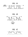
- Fig. 1A shows an example write strategy adopted during high-speed recording operation for DVD-R.
- a vertical axis represents the amplitude of a light beam
- a horizontal axis represents time
- Pw denotes recording power corresponding to a mark segment
- Pr denotes reproduction power corresponding to a space segment.
- Multipulse modulation is usually employed during a low-speed recording operation, but non-multipulse modulation having a substantially M-shaped profile, such as that indicated by a second or third strategy waveform shown in Fig. 1A, is employed during high-speed recording operation.
- T denotes the cycle of one channel clock pulse which is a unit length corresponding to an interval between bits specified by a recording format at the time of recording of recording data
- a strategy waveform which sets power lower than the recording power Pw at an intermediate portion and which sets the recording power Pw at the time of rise and fall of the pulse.
- Fig. 1B shows a signal LAD1 formed by: receiving light generated as a result of a laser beam whose intensity has been modified by the write strategy signal shown in Fig. 1A having been reflected from the recording medium, through use of a four-split detector; and adding together two of the four received-light signals.
- the four-split detector 10 receives the reflected light consisting of a light beam BM radiated on a groove 102 and a portion of a land 103, both being formed in the recording medium, through use of four regions A to D split by parting lines corresponding to the radial direction of the disk and the direction of the track.
- Fig. 1B shows the signal LAD1 generated by adding together a received-light signal of the region A and a received-light signal of the region D.
- impulse-shaped components TR which are unique to recording of data on a pigment-based disk, arise in the leading edges of the write strategy shown in Fig. 1A ( in initial phase of formation of a mark).
- the signal subsequent to the impulse component TR assumes a substantially constant level.
- the shape of the impulse component TR changes in accordance with a recording speed and also varies slightly in accordance with a recording medium.
- the shape of the impulse component TR is substantially constant without dependence on the length of a mark to be recorded when data are recorded on the same recording medium, and the level of the signal subsequent to the impulse component TR becomes substantially constant until the end of formation of the mark.
- Analogous characteristics are exhibited by a signal formed by adding together the received-light signal and the received-light signal, both belonging to the regions B and C from among the four regions A to D.
- FIG. 1C A signal having passed through the filter is shown in Fig. 1C.
- Fig. 1C after the signal has passed through the filter, the shape of a waveform appearing at an initial phase of the mark section does not become extremely dull and becomes substantially equal to the original signal, thereby rendering the entire mark section flat.
- the shape of the impulse component TR becomes substantially constant regardless of the length of the mark to be recorded during operation for recording data on a single medium, and hence all mark sections can be made equally flat.
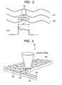
- Fig. 3 shows the signal LAD1 appearing when a mark is recorded at the position of a land prepit 104 formed in the land 103. This shows a case where a mark having a duration of 14T is recorded as a synchronous pattern SY of the synchronization frame.
- the signal LAD1 which appears when a mark is recorded at the position of the land prepit 104 includes a received-light component of the land prepit 104. Further, the level of a portion of the signal LAD1 subsequent to the impulse component TR is not constant, and a center of the portion has a higher level.
- the level achieved at a position subsequent to the impulse component TR becomes stable at a substantially constant level until the end of formation of the mark.
- the land prepit signal partially overlapping the mark section has a high level, and the resultant component still remains in the signal even after the signal has been caused to pass through the previously-described filter.
- a first embodiment of the present invention will be described by reference to Figs. 4 through 10.
- the following embodiment shows a land prepit detecting apparatus for detecting land prepits from a DVD-R or the like, serving as a recording medium (hereinafter called a "disk"), in which address data representing positions on the recording medium where data are to be recorded and a reference signal used for generating a clock signal to be used for recording and reproducing operations are formed in the form of land prepits.
- Fig. 4 is a cross-sectional perspective view of a disk 56 of the first embodiment.
- the disk 56 is a pigment-based disk which has a pigment film 105 and enables writing of data only one time.
- Formed in the disk 56 are grooves 102 serving as data tracks on which recording data are to be recorded and lands 103 serving as guide tracks for guiding a light beam BM, such as a laser beam, which has reproduction or recording power to the groove 102.
- Land prepits 104 are formed in the land 103.
- the land prepit 104 is formed in a line crossing, at right angles, a tangential direction of the groove 102 such that the land prepits 104 do not oppose each other with the groove 102 interposed therebetween.
- the disk also has a protective film for protecting the lands, the land prepits, and the grooves, and a reflection film 106 for reflecting the light beam BM at the time of reproduction of recorded data.
- the grooves 102 are wobbled at a frequency which serves as a standard for the rotational speed of the disk 56.
- recording data i. e. , data to be originally recorded, such as image data, other than preliminary information and a synchronous signal
- the wobbling frequency of the groove 102 is detected to acquire a synchronous signal, whereupon the disk 56 is rotationally controlled at a predetermined rotational speed.
- the land prepits 104 are detected, thereby acquiring the preliminary information beforehand.
- Address data which indicate a position on the disk 56 where the recording data are to be recorded, are acquired from the preliminary information, and on the basis of the address data the recording data are recorded in a corresponding recording position.
- the light beam BM is radiated such that the center of the beam coincides with the center of the groove 102, to thus form a recorded data pit ( i. e. , a mark section) corresponding to the recording data in the groove 102, whereupon the recording data are formed.
- the size of a light spot is set such that a portion of the spot falls on the land 103 as well as on the groove 102.
- the preliminary information is detected from the land prepits 104 by the push-pull method through use of reflected light consisting of a portion of the light spot radiated on the land 103, whereby the preliminary information is acquired.
- a wobbling signal is detected from the groove 102, so that a clock signal to be used for controlling rotation is acquired.
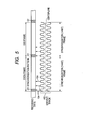
- FIG. 5 is a schematic representation showing the preliminary information recorded in the disk 56 beforehand and the format at which the rotation control data are to be recorded.
- an upper row shows a format at which the recording data are to be recorded
- a lower waveform shows a wobbling state of the groove where the recording data are to be recorded (i.e., the plane view of the groove 102).
- Upward arrows provided between the recording data and the wobbling state of the groove 102 schematically show positions where the land prepits 104 are to be formed.
- the land prepits 104 are formed at positions where wobbling of the groove 102 has the maximum amplitude.
- the wobbling state of the groove 102 is indicated through use of an amplitude which is larger than an actual amplitude, for the sake of easy comprehension, and the recording data are recorded on the center line of the groove 102.
- the recording data to be recorded on the disk 56 have been divided on a per-synchronization-frame basis in advance.
- One recording sector serving as a data unit, is formed from 26 synchronization frames.
- one ECC block serving as a data block, is formed from 16 recording sectors.
- One synchronization frame has a length which is 1488 times (1488T) the cycle of one channel clock, wherein the clock is a unit length corresponding to an interval between bits defined by a recording format employed at the time of recording of recording data.
- a synchronization pattern SY to be used for maintaining synchronization on a per-synchronization-frame basis is recorded in a leading portion of one synchronization frame having a length 14T.
- the preliminary information recorded in the disk 56 is recorded on a per-synchronization-frame basis.
- at least one land prepit 104 is inevitably formed on the land 103 adjacent to the area where the synchronization patterns SY in the synchronization frames of the recording data are to be recorded, as one which indicates a synchronization signal in the preliminary information.
- Two or one land prepit 104 is formed in the land 103 adjacent to a first half of the synchronization frame other than the synchronization pattern SY as one which indicates contents (i.e., address data) of the preliminary information to be recorded.
- the land prepits 104 are formed in only the even-numbered synchronous frames (hereinafter referred to as "EVEN frames") in one recording sector, or the land prepits 104 are formed in only the odd-numbered synchronous frames (hereinafter referred to as "ODD frames"), whereby the preliminary information is recorded.
- EVEN frames even-numbered synchronous frames
- ODD frames odd-numbered synchronous frames
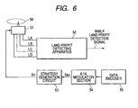
- FIG. 6 is a block diagram showing a schematic configuration of a portion of the recording and reproduction apparatus for the disk 56 to which the land prepit detecting apparatus of the first embodiment of the invention is applied, wherein the portion pertains to the land prepit detecting apparatus.
- the recording and reproduction apparatus comprises the disk 56, a pickup 51, a land prepit detecting apparatus 52, a strategy generation circuit 53, an 8-16 modulation section 54, and a data encoder 55.
- the data encoder 55 encodes recording data input from the outside.
- the 8-16 modulation section 54 subjects the recording data that have been encoded on the basis of the recording clock to 8-16 modulation, thereby generating an NRZI (Non-Return to Zero Invert) signal Sec and outputting the thus-generated NRZI signal Sec to the strategy generation circuit 53.
- the strategy generation circuit 53 subjects the NRZI signal Sec to waveform conversion for adjusting the geometry of recording bits to be formed in the disk 56, to thus generate a write strategy signal Srr.
- the pickup 51 radiates a light beam whose intensity has been modulated by the write strategy signal Srr on the groove 102 where pits corresponding to the recording data are to be formed, thereby recording on the disk 56 the data to be recorded. Further, the pickup 51 has the four-split detector 10 that is shown in Fig. 2 and serves as a light-receiving element, and the light which consists of the light beam BM and has been reflected from the disk 56 is received by the four-split detector 10. The four-spilt detector 10 outputs received-light signals LA, LB, LC, and LD of the four regions A to D which are split into four in the radial direction of the disk 56 and in the direction of the track.
- the land prepit detecting apparatus 52 detects a land prepit on the basis of the received-light signals LA, LB, LC, and LD input from the four-split detector 10.
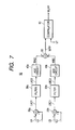
- Fig. 7 is a block diagram showing the internal configuration of the land prepit detecting apparatus 52 shown in Fig. 6.
- the land prepit detecting apparatus 52 has two adders 20a, 20b; filters 30a, 30b serving as filtering device; AGC (Automatic Gain Control) circuits 40a, 40b serving as first and second amplitude control device; a subtracter 50 serving as computation device; and a comparator 60 serving as detection device.
- AGC Automatic Gain Control
- the adder 20a adds the received-light signal LA to the received-light signal LD, thereby generating a signal LAD1.
- the adder 20b adds the received-light signal LB to the received-light signal LC, thereby generating a signal LBC1.
- the filter 30a attenuates the impulse components of the signal LAD1, thereby generating the signal LAD2.
- the filters 30a and 30b have the same filtering characteristic.
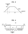
- Fig. 8 is a view showing an example of the filtering characteristic of the filter 30a shown in Fig. 7.
- the filter 30a attenuates the impulse components of the signal LAD1 by a primary low-pass filter having a cut-off frequency of 1/20T and an attenuation gradient of -6dB/oct and eliminates fluctuations in the signal LAD1 due to eccentric components of the disk, through use of a high-pass filter having a cut-off frequency of fL.
- the cut-off frequency fL of the high-pass filter assumes a value of about 20 kHz
- the cut-off frequency of the low-pass filter assumes a value of about 1.35 MHz.
- the cut-off frequency fL of the high-pass filter assumes a value of about 80 kHz
- the cut-off frequency 1/20T of the low-pass filter assumes a value of about 10.8 MHz.
- the AGC circuit 40a corrects the amplitude of the signal LAD2 to a predetermined reference value, to thus generate a signal WAD.
- Fig. 9 is a block diagram showing the configuration of the AGC circuit 40a shown in Fig. 7.
- the AGC circuit 40a is equipped with a gain control amplifier 41, an amplitude detector 42, a low-pass filter 43, a subtracter 44, and an integrator 45.
- the gain control amplifier 41 generates the signal WAD that is formed by correcting the amplitude of the signal LAD2 on the basis of the gain control signal input from the integrator 45.
- the amplitude detector 42 detects the amplitude of the signal WAD by holding a peak and a bottom of the signal.
- the low-pass filter 43 eliminates high-frequency components of the amplitudedetected by the amplitude detector 42.
- the subtracter 44 generates a gain control signal by subtracting the predetermined reference level from the amplitude from which the high-frequency components have been removed.
- the integrator 45 integrates the gain control signal, thereby adjusting the time of the gain control signal output to the gain control amplifier 41. Specifically, the integrator 45 adjusts a response speed of the AGC circuit 40a.
- the AGC circuit 40b corrects the amplitude of the signal LBC2 to a predetermined reference value, thereby generating a signal WBC.
- the configuration of the AGC circuit 40b is analogous to that of the AGC circuit 40a shown in Fig. 9 except for a difference in the predetermined reference value to be used for comparison by the subtracter 44, and hence its explanation is omitted.
- the subtracter 50 subtracts the signal WBC from the signal WAD, thereby generating the radial push-pull signal WPP.
- the comparator 60 compares a reference level VT, which is a predetermined reference value to be used for detecting a land prepit, with the radial push-pull signal WPP. When the level of the radial push-pull signal WPP is determined to be higher than the reference level VT as a result of comparison, a signal indicating detection of a land prepit is output as the land prepit detection signal WLPP.
- a signal indicating a failure to detect a land prepit is output as the land prepit detection signal WLPP. For instance, when the land prepit is detected, the comparator 60 brings the land prepit detection signal WLPP to an "H” position. When no land prepit is detected, the comparator 60 brings the land prepit detection signal WLPP to an "L" position.
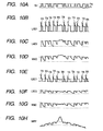
- the pickup 51 modulates the intensity of the light beam by the write strategy signal Srr shown in Fig. 10A and radiates the light beam BM whose intensity has been modified on the groove 102 where a pit corresponding to the recording data is to be formed, thereby recording on the disk 56 the data to be recorded.
- the write strategy signal Srr shown in Fig. 10A is modified by non-multipulse modulation. However, for the sake of simplification, a strategy waveform used for recording 5T to 11T and 14T, which have a substantially M-shaped form, is also expressed in the form of a rectangular pulse.
- the four-split detector 10 provided in the pickup 51 receives the reflected light consisting of the light beam BM whose intensity has been modified by the write strategy signal Srr shown in Fig. 10A, thereby outputting the received-light signal LA of the region A and the received-light signal LD of the region D to the adder 20a and the received-light signal LB of the region B and the received-light signal LC of the region C to the adder 20b.
- the adder 20a adds together the received-light signal LA and the received-light signal LD, to thus generate the signal LAD1.
- Fig. 10B shows the signal LAD1 generated by the adder 20a.
- a large impulse component TR develops in the signal LAD1 at a time in point when the write strategy signal Srr shown in Fig. 10A rises (i.e., the initial phase of formation of the mark).
- the adder 20a outputs the signal LAD1 to the filter 30a.
- the adder 20b adds together the received-light signal LB and the received-light signal LC, to thus generate the signal LBC1.
- Fig. 10E shows the signal LBC1 generated by the adder 20b.
- a large impulse component TR develops in the signal LBC1 at a time in point when the write strategy signal Srr shown in Fig. 10A rises.
- the adder 20a outputs the signal LAD1 to the filter 30a.
- the filter 30a eliminates a component of fL [Hz] or less and a component of 1/20T [Hz] or more, both belonging to the signal LAD1, to thus generate the signal LAD2.
- FIG. 10C shows the signal LAD2 produced as a result of the filter 30a having eliminated the component of fL [Hz] or less and the component of 1/20T [Hz] or more, both belonging to the signal LAD1 shown in Fig. 10B.
- the signal LAD2 is formed as a result of elimination of the impulse components TR from the signal LAD1.
- the filter 30a outputs the signal LAD2 to the gain control amplifier 41 of the AGC circuit 40a.
- the filter 30b eliminates a component of fL [Hz] or less and a component of 1/20T [Hz] or more, both belonging to the signal LBC1, to thus generate the signal LBC2.
- Fig. 10F shows the signal LBC2 produced as a result of the filter 30b having eliminated the frequency component of fL [Hz] or less and the high-frequency component of 1/20T [Hz] or more, both belonging to the signal LBC1 shown in Fig. 10E.
- the signal LAD2 is formed as a result of elimination of the impulse components TR from the signal LBC1.
- the filter 30b outputs the signal LBC2 to the gain control amplifier 41 of the AGC circuit 40b.
- the gain control amplifier 41 of the AGC circuit 40a corrects the amplitude of the signal LAD2 in accordance with the gain control signal input from the integrator 45 of the AGC circuit 40a, to thus generate the signal WAD.
- the signal WAD is output to the amplitude detector 42 of the AGC circuit 40a and the subtracter 50.
- the amplitude detector 42 of the AGC circuit 40a detects the amplitude of the signal WAD by holding a peak and a bottom of the signal and outputs the thus-detected amplitude to the low-pass filter 43 of the AGC circuit 40a.
- the low-pass filter 43 of the AGC circuit 40a eliminates a high-frequency component of the amplitude detected by the amplitude detector 42 of the AGC circuit 40a and outputs the amplitude from which the high-frequency component has been removed to the subtracter 44 of the AGC circuit 40a.
- the subtracter 44 of the AGC circuit 40a subtracts the predetermined reference level from the amplitude from which the high-frequency component has been removed, to thus generate the gain control signal.
- the thus-generated gain control signal is output to the integrator 45 of the AGC circuit 40a.
- the integrator 45 of the AGC circuit 40a integrates the gain control signal, thereby controlling the time of the gain control signal, and outputs the gain control signal to the gain control amplifier 41 of the AGC circuit 40a.
- Fig. 10D shows the signal WAD that has undergone amplitude correction performed by the AGC circuit 40a. As shown in Fig. 10D, the amplitude of the signal LAD2 is corrected.
- the AGC circuit 40b corrects the amplitude of the signal LAD2 to a predetermined reference value, to thus generate the signal WBC.
- Internal operation of the AGC circuit 40b becomes identical with that of the previously-described AGC circuit 40a, and hence its explanation is omitted here.
- Fig. 10G shows the signal WBC that has undergone amplitude correction performed by the AGC circuit 40b. As shown in Fig. 10G, the amplitude of the signal LBC2 is corrected, to thus become equal to the amplitude of the signal WAD shown in Fig. 10D.
- the subtracter 50 generates the radial push-pull signal WPP by subtracting the signal WBC from the signal WAD.
- Fig. 10H shows the radial push-pull signal WPP.
- the impulse components TR included in the signal LAD1 and the second signal LBC2 are made flat by the filters 30a and 30b. Therefore, unwanted components which are larger than an upper envelope of the wobble signal indicated by dotted lines are eliminated from the radial push-pull signal WPP shown in Fig. 10H, with the exception of the land prepits.
- the subtracter 50 outputs the radial push-pull signal WPP to the comparator 60.
- the comparator 60 compares the predetermined reference level VT to be used for detecting land prepits with the radial push-pull signal WPP.
- the land prepit detection signal WLPP indicating detection of a land prepit is output to an unillustrated recording clock generation LPP PLL (Phase-locked Loop) section.
- LPP PLL Phase-locked Loop
- the land prepit detection signal WLPP indicating a failure to detect a land prepit is output to the unillustrated recording clock generation LPP PLL section.
- the PLL section for LPP generates a recording clock signal, which is to act as a reference for recording data on the disk 56, in accordance with the land prepit detection signal WLPP.
- the filter 30a generates the signal LAD2 from which the impulse components TR included in the signal LAD1 have been removed
- the filter 30b generates the signal LBC2 from which the impulse components TR included in the signal LBC1 have been removed.
- a land prepit located in the mark segment is detected on the basis of the radial push-pull signal WPP and through use of the signals LAD2 and LBC2 from which the impulse components TR have been removed. Even during a high-speed recording operation, such as a 4x recording operation, 8x recording operation, or 16x recording operation, land prepits can be detected accurately.
- the AGC circuits 40a, 40b adjust the amplitudes of the signals LAD2, LBC2 from which the filters 30a, 30b have removed the impulse components TR. Therefore, the requirements for the amplitude detectors 42 in the AGC circuits 40a, 40b are to detect the amplitudes of the signals WAD, WBC which are free from impulse components. Since the amplitudes of the signals can be detected accurately by holding peaks, operations of the AGC circuits 40a, 40b become stable, and accurate amplitude control can be performed.
- the filters 30a, 30b are configured to have a filtering characteristic shown in Fig. 8. Specifically, the cut-off frequency of the low-pass filter for eliminating impulse components is set to 1/20T. Therefore, as shown in Fig. 10H, in the segments other than the location of the land prepit there can be generated the radial push-pull signal WPP, wherein the mark section is made evenly uniform, and noise components larger than the upper envelope of the wobble signal indicated by dotted lines have been removed.
- Figs. 11A to 11C and Figs. 12A to 12F the radial push-pull signal WPP will now be described in connection with a case where the cut-off frequency of the low-pass filter for removing impulse components is higher than a level required to make the mark section flat, where the cut-off frequency is appropriate; and where the cut-off frequency is lower than the required level.
- Figs. 11A to 11C show the radial push-pull signals WPP obtained when three different types of cut-off frequencies are set. Figs.
- FIG. 12A to 12F diagrammatically show waveforms obtained when the radial push-pull signals WPP located in the vicinity of the synchronization pattern during the synchronized recording operation (when recording operation is performed such that the synchronization pattern of the synchronization frame is brought into conformance to the land prepit) are observed through use of an oscilloscope.
- the filters 30a and 30b cannot sufficiently eliminate the impulse components from the signals LAD1 and LBC1. Therefore, the filters 30a and 30b output the signals LAD2 and LBC2, which still include the impulse components, to the AGC circuits 40a, 40b. Therefore, the signals WAD and WBC, which still include the impulse components, are generated. Therefore, as shown in Fig. 11A, the impulse components still remain in the radial push-pull signal WPP.
- the filters 30a, 30b render the impulse components of the signals LAD1 and LBC1 flat. Therefore, as shown in Fig. 11B, noise components larger than the upper envelope of the wobble signal are eliminated from the radial push-pull signal WPP, with the exception of the land prepit.
- the comparator 60 can accurately detect the land prepit.
- the filters 30a and 30b output the signals LAD2 and LBC2, whose impulse components have undergone overcorrection, to the AGC circuits 40a and 40b. Therefore, the signals WAD and WBC, whose impulse components have undergone overcorrection, are generated. Consequently, as shown in Fig. 11C, the radial push-pull signal WPP is not flat but rise upwardly with reference to the upper envelope of the wobble signal during the period of generation of a mark.
- the f ilters 30a, 30b for rendering the impulse components flat are provided in a stage before the AGC circuits 40a, 40b.
- filters 31a to 31d having the same filtering characteristic as those of the filters 30a, 30b may be disposed in a stage before the adders 20a, 20b.
- impulse components are removed from the received-light signals LA to LD which have been received by the four regions A to D and input from the four-split detector 10.
- the adders 20a and 20b add together the received-light signals which are free of impulse components.
- Signals analogous to the signals LAD2 and LBC2, which are shown in Figs. 10C and 10D can be output to the AGC circuits 40a, 40b. Consequently, even in this case, there can be yielded the same advantage as that yielded by the land prepit detecting apparatus 52 shown in Fig. 7.
- a second embodiment of the present invention will be described by reference to Figs. 14 and 15.
- the impulse components are eliminated before the amplitude of the signal is adjusted through use of the AGC circuits 40a, 40b.
- the filtering operation for eliminating impulse components can be inserted to any arbitrary position, so long as the position is located before the comparator 60 which compares the radial push-pull signal with the predetermined reference level to be used for detecting a land prepit.
- the radial push-pull signal is generated while still including the impulse components, and the impulse components are eliminated immediately before comparison of the signal with the predetermined reference level.
- Fig. 14 is a block diagram showing the internal configuration of the land prepit detecting apparatus of the second embodiment of the invention.
- the land prepit detecting apparatus of the second embodiment has a filter 30c interposed between the subtracter 50 and the comparator 60, and, in place of the AGC circuits 40a, 40b, AGC circuits 40c, 40d constituting another internal configuration.
- Those constituent portions which have the same functions as those of the land prepit detecting apparatus 52 of the first embodiment shown in Fig. 7 are assigned the same reference numerals, and their repeated explanations are omitted.
- the AGC circuit 40c corrects the amplitude of the signal LAD1 to the predetermined reference value, to thus generate a signal WAD1.
- Fig. 15 is a block diagram showing the internal configuration of the AGC circuit 40c shown in Fig. 14.
- a filter 46 serving as a filtering section is added to a stage in front of an amplitude detector 42 of the AGC circuit 40a shown in Fig. 9.
- Those constituent portions which have the same functions as those of the AGC circuit 40a shown in Fig. 9 are assigned the same reference numerals, and their repeated explanations are omitted.
- the signal LAD1 includes impulse components TR. Therefore, the signal WAD1 formed as a result of the amplitude of the signal LAD1 being corrected also includes the impulse components. Since the impulse components have an impulse-shaped profile, the amplitude detector 42 cannot detect an accurate amplitude of the signal WAD1 through peak holding operation. For this reason, the gain control signal for controlling the gain control amplifier 41 becomes unstable, and hence correction of amplitude of the signal LAD1 cannot be performed accurately.
- a filter 46 having the filtering characteristic as that shown in Fig. 8 is provided in a stage in front of the amplitude detector 42, thereby eliminating the impulse components from the signal WAD1. As a result, a signal equivalent to the signal LAD2 of the first embodiment is input to the amplitude detector 42, thereby enabling accurate correction of the amplitude.
- the AGC circuit 40d corrects the amplitude of the signal LBC1 to the predetermined reference value, to thus generate a signal WBC1.
- the configuration of the AGC circuit 40d is analogous to that of the AGC circuit 40c shown in Fig. 15, except that the predetermined reference level to be used for comparison performed by the subtracter 44 is different, and hence its explanation is omitted here.
- the signals WAD1 and WBC1 include the impulse components. Therefore, a radial push-pull signal WPP1 generated by subtracting the signal WBC1 from the signal WAD1 through use of the subtracter 50 also includes the impulse components.
- the filter 30c has the same filtering characteristic as that shown in Fig. 8 and eliminates the impulse components from the radial push-pull signal WPP1. As a result, in segments other than the location of the land prepit there is produced a radial push-pull signal WPP2 from which the impulse components larger than the upper envelope of the wobble signal are eliminated.
- the adder 20a adds together the received-light signals LA and LD, to thus generate the signal LAD1.
- the signal LAD1 is output to the AGC circuit 40c.
- the gain control amplifier 41 of the AGC circuit 40c corrects the amplitude of the signal LAD1 in accordance with the gain control signal input from the integrator 45 of the AGC circuit 40c and outputs the signal WAD1 to the filter 46 of the AGC circuit 40c and the subtracter 50.
- the filter 46 of theAGC circuit 40c eliminates the impulse components included in the signal WAD1.
- the signal WAD1 from which the impulse components have been removed is output to the amplitude detector 42 of the AGC circuit 40c.
- the amplitude detector 42 of the AGC circuit 40c detects the amplitude of the signal WAD1, from which the impulse components have been removed, by holding a peak and a bottom and outputs the thus-detected amplitude to the low-pass filter 43 of the AGC circuit 40c.
- the low-pass filter 43 of the AGC circuit 40c eliminates high-frequency components from the amplitude detected by the amplitude detector 42 of the AGC circuit 40c and outputs the amplitude, from which the high-frequency components have been removed, to the subtracter 44 of the AGC circuit 40c.
- the subtracter 44 of the AGC circuit 40c subtracts the predetermined reference level from the amplitude from which the high-frequency components have been removed, to thus generate the gain control signal, and outputs the gain control signal to the integrator 45 of the AGC circuit 40c.
- the integrator 45 of the AGC circuit 40c integrates the gain control signal, to thus adjust the time of the gain control signal, and outputs the gain control signal to the gain control amplifier 41 of the AGC circuit 40c. Consequently, although the signal WAD1 output from the AGC circuit 40c includes the impulse components, the amplitude is controlled so as to become substantially equivalent to the reference level of the signal amplitude from which the impulse components have been removed.
- the adder 20b adds together the received-light signal LB and the received-light signal LC, to thus generate a signal LBC1.
- the signal LBC1 is output to the AGC circuit 40d.
- the AGC circuit 40d corrects the amplitude of the signal LBC1 to the predetermined reference level, to thus generate the signal WBC1.
- Internal operation of the AGC circuit 40d is analogous to that of the previously-described AGC circuit 40c, and hence its explanation is omitted. Consequently, although the signal WBC1 output fromtheAGC circuit 40d includes the impulse components, the amplitude is controlled so as to become substantially equivalent to the reference level of the signal amplitude from which the impulse components have been removed.
- the subtracter 50 subtracts the signal WBC1 from the signal WAD1, to thus generate the radial push-pull signal WPP1.
- the radial push-pull signal WPP1 is output to the filter 30c.
- the filter 30c makes the impulse components of the radial push-pull signal WPP1 flat, whereby there is generated a radial push-pull signal WPP2 in which noise components larger than the upper envelope of the wobble signal are eliminated from the signal, with the exception of a land prepit.
- the radial push-pull signal WPP2 is output to the comparator 60.
- the comparator 60 compares the reference level VT serving as a predetermined reference to be used for detecting a land prepit with the radial push-pull signal WPP.
- the land prepit detection signal WLPP indicating detection of a land prepit is output to an unillustrated recording clock generation LPP PLL section.
- the land prepit detection signal WLPP indicating a failure to detect a land prepit is output to the recording clock generation LPP PLL.
- the filter 30c generates the radial push-pull signal WP2 from which the impulse components included in the signal WPP1 have been removed.
- a land prepit located in the mark segment is detected on the basis of the radial push-pull signal WPP2 from which the impulse components have been removed.
- the filter 46 for eliminating impulse components is provided in each of the AGC circuits 40c, 40d, to thereby detect the amplitude of the signal WAD1 and that of the signal WBC1, from which the impulse components have been removed. Hence, accurate amplitude control can be performed without being affected by the influence of the impulse components.
- a third embodiment of the invention will be described by reference to Figs. 16 through 19.
- the third embodiment describes the characteristic of the filter to be used for eliminating the impulse components.
- the impulse components of the signal LAD1 are attenuated by the primary low-pass filter having a cut-off frequency of 1/20T and an attenuation gradient of -6dB/oct. Further, variations in the signal LAD1 attributable to the eccentric component of the disk are eliminated by a high-pass filter having a cut-off frequency fL.
- a secondary low-pass filter having a characteristic such as that shown in Fig. 16 is added to the filter shown in Fig. 8.
- the filtering characteristic shown in Fig. 16 is as follows: a Q value, which is one factor of a transmission characteristic, being set to a small value; the cut-off frequency being set to 1/10T, which is substantially equal to the fundamental frequency of the land prepit; and the attenuation gradient being set to -12dB/oct, which is steeper than the filtering characteristic shown in Fig. 8.
- the filter intended for eliminating impulse components is additionally provided with the secondary filter for eliminating noise components higher than the fundamental frequency of the land prepit.
- Fig. 17 shows a general filtering characteristic achieved as a result of the filter shown in Fig. 16 having been added to the filter shown in Fig. 8.
- the filtering characteristic shown in Fig. 17 as a result of addition of the secondary low-pass filter having the Q value set to a small value, the cut-off frequency set to 1/10T, and the attenuation gradient of -12dB/oct, the slope of the attenuation gradient from 1/10T, which is substantially equal to the fundamental frequency of the land prepit, becomes greater than the attenuation gradient of a frequency region lower than 1/10T.
- the attenuation gradient ranges from -6dB/oct to -18dB/oct.
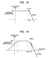
- a secondary low-pass filter wherein the Q value is set to a large value; the cut-off frequency is set to 1/10T; and the attenuation gradient is -12 dB/oct.
- the cut-off frequency is set to 1/10T, which is substantially equal to the fundamental frequency of the land prepit, and the Q value is set to a large value.
- Fig. 19 shows a filtering characteristic achieved as a result of the filtering characteristic shown in Fig. 18 having been added to the filtering characteristic shown in Fig. 8.
- the filtering characteristic shown in Fig. 19 as a result of addition of the secondary low-pass filter having the Q value set to a large value, the cut-off frequency set to 1/10T, and the attenuation gradient of -12dB/oct, the slope of the attenuation gradient from 1/10T, which is substantially equal to the fundamental frequency of the land prepit, becomes greater than the attenuation gradient of a frequency region lower than 1/10T. Further, the amplitude characteristic of 1/10T substantially equivalent to the fundamental frequency of the land prepit is increased.
- the disk recording medium is not limited to a DVD-R or DVD-RW.
Landscapes
- Optical Recording Or Reproduction (AREA)
- Signal Processing For Digital Recording And Reproducing (AREA)
- Optical Radar Systems And Details Thereof (AREA)
Abstract
Description
Claims (6)
- A land prepit detecting apparatus which radiates a light beam corresponding to a recording signal onto a recording medium having recording tracks and land prepits previously formed thereon, to thus detect said land prepits, the apparatus comprising:first and second light-receiving elements which are divided at least into sub-divis ions by split lines corresponding to the direction of said recording track and which receive reflected light formed from said light beam radiated onto said recording medium;a generation device for generating a radial push-pull signal on the basis of outputs from said first and second light-receiving elements;a detection device which compares said radial push-pull signal with a predetermined reference value, to thereby detect said land prepit during a period of irradiation of said light beam to be used for forming a mark section in said recording track; anda filtering device which is interposed between the first and second light-receiving elements and said detection device and which attenuates an impulse component developing in association with a variation in said recording signal.
- The land prepit detecting apparatus according to claim 1, further comprising:a first and second amplitude control device for controlling, to a predetermined amplitude, the amplitudes of received-light outputs from said first and second light-receiving elements.
- The land prepit detecting apparatus according to claim 2, wherein
said filtering device corresponds to first and second filters provided at a stage before the first and second amplitude control device. - The land prepit detecting apparatus according to claim 2, wherein
said first and second amplitude control device have a filter section for attenuating impulse components included in an input of said recording signal in association with changes in said recording signal, and
said filtering device is interposed between said generation device and said detection device. - The land prepit detecting apparatus according to claim 1, wherein
said filtering device is a low-pass filter having a predetermined cut-off frequency. - A land prepit detecting method comprising the steps of:radiating a light beam corresponding to a recording signal onto a recording medium having recording tracks and land prepits previously formed thereon;receiving reflected light formed from said light beam radiated onto said recording medium, through use of light-receiving elements which are divided at least into sub-divisions by split lines corresponding to the direction of said recording track;generating a radial push-pull signal on the basis of outputs from said first and second light-receiving elements;attenuating an impulse component developing in association with a variation in said recording signal through filtering operation; anddetecting said land prepit during a period of irradiation of said light beam to be used for forming a mark section in said recording track by comparing said radial push-pull signal with a predetermined reference value.
Applications Claiming Priority (2)
| Application Number | Priority Date | Filing Date | Title |
|---|---|---|---|
| JP2003206978 | 2003-08-08 | ||
| JP2003206978A JP4357890B2 (en) | 2003-08-08 | 2003-08-08 | Land pre-pit detection apparatus and method |
Publications (2)
| Publication Number | Publication Date |
|---|---|
| EP1505578A2 true EP1505578A2 (en) | 2005-02-09 |
| EP1505578A3 EP1505578A3 (en) | 2007-09-12 |
Family
ID=33549921
Family Applications (1)
| Application Number | Title | Priority Date | Filing Date |
|---|---|---|---|
| EP04018701A Withdrawn EP1505578A3 (en) | 2003-08-08 | 2004-08-06 | Apparatus and method for detecting land prepit |
Country Status (4)
| Country | Link |
|---|---|
| US (1) | US20050041563A1 (en) |
| EP (1) | EP1505578A3 (en) |
| JP (1) | JP4357890B2 (en) |
| CN (1) | CN1272775C (en) |
Families Citing this family (11)
| Publication number | Priority date | Publication date | Assignee | Title |
|---|---|---|---|---|
| JP2005158168A (en) * | 2003-11-27 | 2005-06-16 | Pioneer Electronic Corp | Information reading device and prepit detecting circuit |
| JP2005302095A (en) * | 2004-04-08 | 2005-10-27 | Tdk Corp | Reproducing device and information recording medium evaluation device |
| GB0413396D0 (en) * | 2004-06-16 | 2004-07-21 | Koninkl Philips Electronics Nv | Method and apparatus for writing data to an optical disc |
| GB0413647D0 (en) * | 2004-06-18 | 2004-07-21 | Koninkl Philips Electronics Nv | Land pre-pit signal processing method and related apparatus |
| JP2007305229A (en) * | 2006-05-11 | 2007-11-22 | Sony Corp | Optical disc apparatus and land pre-pit reproduction method |
| US20070280069A1 (en) * | 2006-06-05 | 2007-12-06 | Mediatek Inc. | Method of gain control and controller thereof |
| US7693011B2 (en) * | 2006-06-05 | 2010-04-06 | Mediatek Inc. | Wobble detection circuit and method for processing wobble signals |
| US7697380B2 (en) * | 2006-06-05 | 2010-04-13 | Mediatek Inc. | Apparatus for detecting the wobble carrier frequency of an optical disk and method for same |
| US7693012B2 (en) * | 2006-06-05 | 2010-04-06 | Mediatek Inc. | Apparatus for demodulating address in pre-groove symbols and apparatus for decoding pre-pit symbols |
| TWI330364B (en) * | 2006-06-16 | 2010-09-11 | Realtek Semiconductor Corp | System and method for land pre-pit signal detecting in optical disk drive |
| EP3119087A4 (en) | 2014-04-01 | 2017-03-22 | Huawei Technologies Co., Ltd. | Adaptive coding and modulation method, apparatus and system |
Family Cites Families (8)
| Publication number | Priority date | Publication date | Assignee | Title |
|---|---|---|---|---|
| US6487149B1 (en) * | 1998-10-09 | 2002-11-26 | Ricoh Company, Ltd. | Optical recording and reproducing methods for optical disk |
| JP3771385B2 (en) * | 1998-12-16 | 2006-04-26 | パイオニア株式会社 | Pickup drive apparatus, pickup drive method, and recording / reproducing apparatus |
| JP3968193B2 (en) * | 1999-04-26 | 2007-08-29 | パイオニア株式会社 | Pre-pit detection device |
| JP2001134943A (en) * | 1999-11-05 | 2001-05-18 | Yamaha Corp | Push-pull signal processing circuit, wobble extracting circuit and prepit detecting circuit, in optical disk recorder |
| JP2002237053A (en) * | 2001-02-09 | 2002-08-23 | Pioneer Electronic Corp | Optical disk read composite signal generating device |
| JP4517534B2 (en) * | 2001-05-11 | 2010-08-04 | ソニー株式会社 | Disk drive device |
| JP4355459B2 (en) * | 2001-07-24 | 2009-11-04 | パイオニア株式会社 | Information recording / reproducing apparatus and pre-pit detecting method |
| TWI238997B (en) * | 2001-09-21 | 2005-09-01 | Teac Corp | Optical device |
-
2003
- 2003-08-08 JP JP2003206978A patent/JP4357890B2/en not_active Expired - Fee Related
-
2004
- 2004-08-06 US US10/912,539 patent/US20050041563A1/en not_active Abandoned
- 2004-08-06 EP EP04018701A patent/EP1505578A3/en not_active Withdrawn
- 2004-08-09 CN CN200410056441.XA patent/CN1272775C/en not_active Expired - Fee Related
Also Published As
| Publication number | Publication date |
|---|---|
| CN1591595A (en) | 2005-03-09 |
| JP2005063474A (en) | 2005-03-10 |
| US20050041563A1 (en) | 2005-02-24 |
| CN1272775C (en) | 2006-08-30 |
| JP4357890B2 (en) | 2009-11-04 |
| EP1505578A3 (en) | 2007-09-12 |
Similar Documents
| Publication | Publication Date | Title |
|---|---|---|
| EP0871169B1 (en) | Pre-pit detecting device and information recording apparatus employing the same | |
| US6556523B1 (en) | Wobble-signal detecting device and information recording apparatus | |
| US20050041563A1 (en) | Apparatus and method for detecting land prepit | |
| JP2000113463A (en) | Prepit detecting device | |
| US6639882B2 (en) | Pre-pit detecting apparatus | |
| US20060203641A1 (en) | Recording clock generating apparatus for a data recording system | |
| US6757233B2 (en) | Pre-pit detecting device and binarizing level setting method | |
| US7558171B2 (en) | Optical disc recording/playback apparatus | |
| JP2002133758A (en) | Recording and playback device | |
| EP0880132A2 (en) | Pre-pit detecting apparatus and method | |
| US6956800B2 (en) | Pre-pit detecting apparatus detecting pre-pit signal from only signals input during period of applying light beam having reproducing power | |
| JP3961338B2 (en) | Optical disk device | |
| EP1225571B1 (en) | Pre-pit detecting apparatus | |
| KR20020044061A (en) | Optical disk device | |
| JP2002197676A (en) | Optical recording medium having wobble header area formed thereon, data recording method, and recording apparatus therefor | |
| JP3714117B2 (en) | Pre-pit detection device, pre-pit detection method, position and frequency signal detection circuit | |
| US20050237884A1 (en) | Information recording apparatus and method, and computer program product | |
| KR100319847B1 (en) | Optical recording media | |
| JP2002074675A (en) | Prepit signal detecor and detecting method | |
| JP2002032962A (en) | Clock signal generator | |
| JP3876601B2 (en) | Land pre-pit detection device and optical disk device using the same | |
| US20070230316A1 (en) | Information Recording Medium, Information Reproducing Apparatus and Method, Information Recording Apparatus and Method, and Computer Program | |
| KR19990048139A (en) | Header signal reading method of optical disc | |
| JP2004327034A (en) | Prepit detector | |
| JP2003099938A (en) | Optical disk drive |
Legal Events
| Date | Code | Title | Description |
|---|---|---|---|
| PUAI | Public reference made under article 153(3) epc to a published international application that has entered the european phase |
Free format text: ORIGINAL CODE: 0009012 |
|
| AK | Designated contracting states |
Kind code of ref document: A2 Designated state(s): AT BE BG CH CY CZ DE DK EE ES FI FR GB GR HU IE IT LI LU MC NL PL PT RO SE SI SK TR |
|
| AX | Request for extension of the european patent |
Extension state: AL HR LT LV MK |
|
| PUAL | Search report despatched |
Free format text: ORIGINAL CODE: 0009013 |
|
| AK | Designated contracting states |
Kind code of ref document: A3 Designated state(s): AT BE BG CH CY CZ DE DK EE ES FI FR GB GR HU IE IT LI LU MC NL PL PT RO SE SI SK TR |
|
| AX | Request for extension of the european patent |
Extension state: AL HR LT LV MK |
|
| 17P | Request for examination filed |
Effective date: 20071113 |
|
| 17Q | First examination report despatched |
Effective date: 20080408 |
|
| AKX | Designation fees paid |
Designated state(s): DE FR GB |
|
| RAP1 | Party data changed (applicant data changed or rights of an application transferred) |
Owner name: PIONEER CORPORATION |
|
| STAA | Information on the status of an ep patent application or granted ep patent |
Free format text: STATUS: THE APPLICATION IS DEEMED TO BE WITHDRAWN |
|
| 18D | Application deemed to be withdrawn |
Effective date: 20120301 |