EP1505301A2 - Self-priming centrifugal pump - Google Patents
Self-priming centrifugal pump Download PDFInfo
- Publication number
- EP1505301A2 EP1505301A2 EP04254164A EP04254164A EP1505301A2 EP 1505301 A2 EP1505301 A2 EP 1505301A2 EP 04254164 A EP04254164 A EP 04254164A EP 04254164 A EP04254164 A EP 04254164A EP 1505301 A2 EP1505301 A2 EP 1505301A2
- Authority
- EP
- European Patent Office
- Prior art keywords
- pump
- shaft
- diaphragm
- output shaft
- cam
- Prior art date
- Legal status (The legal status is an assumption and is not a legal conclusion. Google has not performed a legal analysis and makes no representation as to the accuracy of the status listed.)
- Withdrawn
Links
Images

Classifications
-
- F—MECHANICAL ENGINEERING; LIGHTING; HEATING; WEAPONS; BLASTING
- F04—POSITIVE - DISPLACEMENT MACHINES FOR LIQUIDS; PUMPS FOR LIQUIDS OR ELASTIC FLUIDS
- F04D—NON-POSITIVE-DISPLACEMENT PUMPS
- F04D9/00—Priming; Preventing vapour lock
- F04D9/04—Priming; Preventing vapour lock using priming pumps; using booster pumps to prevent vapour-lock
- F04D9/043—Priming; Preventing vapour lock using priming pumps; using booster pumps to prevent vapour-lock the priming pump being hand operated or of the reciprocating type
-
- F—MECHANICAL ENGINEERING; LIGHTING; HEATING; WEAPONS; BLASTING
- F04—POSITIVE - DISPLACEMENT MACHINES FOR LIQUIDS; PUMPS FOR LIQUIDS OR ELASTIC FLUIDS
- F04D—NON-POSITIVE-DISPLACEMENT PUMPS
- F04D9/00—Priming; Preventing vapour lock
- F04D9/001—Preventing vapour lock
- F04D9/002—Preventing vapour lock by means in the very pump
-
- F—MECHANICAL ENGINEERING; LIGHTING; HEATING; WEAPONS; BLASTING
- F04—POSITIVE - DISPLACEMENT MACHINES FOR LIQUIDS; PUMPS FOR LIQUIDS OR ELASTIC FLUIDS
- F04D—NON-POSITIVE-DISPLACEMENT PUMPS
- F04D9/00—Priming; Preventing vapour lock
- F04D9/02—Self-priming pumps
-
- F—MECHANICAL ENGINEERING; LIGHTING; HEATING; WEAPONS; BLASTING
- F16—ENGINEERING ELEMENTS AND UNITS; GENERAL MEASURES FOR PRODUCING AND MAINTAINING EFFECTIVE FUNCTIONING OF MACHINES OR INSTALLATIONS; THERMAL INSULATION IN GENERAL
- F16H—GEARING
- F16H25/00—Gearings comprising primarily only cams, cam-followers and screw-and-nut mechanisms
- F16H25/08—Gearings comprising primarily only cams, cam-followers and screw-and-nut mechanisms for interconverting rotary motion and reciprocating motion
- F16H25/12—Gearings comprising primarily only cams, cam-followers and screw-and-nut mechanisms for interconverting rotary motion and reciprocating motion with reciprocation along the axis of rotation, e.g. gearings with helical grooves and automatic reversal
- F16H25/125—Gearings comprising primarily only cams, cam-followers and screw-and-nut mechanisms for interconverting rotary motion and reciprocating motion with reciprocation along the axis of rotation, e.g. gearings with helical grooves and automatic reversal having the cam on an end surface of the rotating element
Definitions
- the present invention relates to centrifugal pumps and more particularly to a self-priming centrifugal pump.
- a basic centrifugal pump is not self-priming, and various self-priming centrifugal pumps have been developed.
- a self-priming centrifugal pump is provided with a discharge tank contained in the pump housing and connected to recirculate liquid through the pumping chamber for priming.
- These tanks are initially provided with a supply of the liquid to be pumped and, during priming, the pump impeller is rotatably driven to recirculate liquid from the tank through the pumping chamber, so that gas in the pumping chamber becomes entrained with the recirculated liquid.
- an additional external pump is provided simply for priming, for example a liquid piston pump functioning as a priming wheel.
- a self-priming centrifugal pump comprising:
- a diaphragm arrangement can be integrated into a pump design without taking up significant additional space. By driving the diaphragm arrangement with the motor, no additional power source is required.
- the impeller is rotated about an output shaft of the motor, and the diaphragm arrangement is driven for reciprocating movement parallel to the output shaft.
- This reciprocating movement provides a pumping operation, in combination with the inlet and outlet valves, and which is suitable for priming the centrifugal pump.
- Means is preferably provided for converting rotation of the output shaft into reciprocating movement for driving the diaphragm.
- the means for converting comprises a pair of cam wheels rotating about the output shaft, at least one diaphragm drive element being sandwiched between the cam wheels, the drive element being coupled to an associated diaphragm.
- a fixed distance is provided between the profiles of the faces of the cam wheels which face each other.
- a fixed sized drive element can then be mounted between the cam wheels, and rotation of the cam wheels causes the drive element to move backwards and forwards parallel to the axis of the output shaft.
- a plurality of diaphragm drive elements can be provided, and a plurality of associated diaphragms can be mounted in a carrier, the carrier being mounted around the output shaft but not rotating with the output shaft.
- This arrangement enables a diaphragm carrier to be mounted around the output shaft at a fixed axial position. This makes sealing of the diaphragm carrier around the output shaft easier.
- the diaphragms can then be provided in a circle around the central axis, and they are controlled (synchronously) by the drive elements.
- the output shaft of the motor can comprise first and second shaft members, a first shaft member for rotating the impeller at a first angular speed, and a second shaft member for rotating the cam wheels at a second, lower, angular speed. These first and second shaft members may be concentric about a common axis.
- the means for converting comprises a diaphragm drive shaft slidable axially with respect to the motor output shaft and an annular cam member mounted around the diaphragm drive shaft and defining a cam channel which varies in axial position around the annular cam member.
- the cam member rotates with respect to the diaphragm drive shaft, and a linkage is provided for fixing the axial position of the diaphragm drive shaft with respect to the cam channel.
- This arrangement converts angular rotation into reciprocal motion by making the diaphragm drive shaft follow an annular channel which traces a path which moves parallel to the axis of the motor output shaft as well as around the axis of the shaft.
- the output shaft of the motor may comprise first and second shaft members, a first shaft member for rotating the impeller at a first angular speed, and a second shaft member for rotating the cam member with respect to the diaphragm drive shaft at a second, lower, angular speed.
- the second shaft member may be provided with a clutch, so that the means for converting can turned on or off.
- the clutch can operate automatically in dependence on the direction of rotation, so that priming is carried out by driving the motor in one direction, and pumping is carried out by driving the motor in the opposite direction.
- invention can use a device for converting angular rotation into linear reciprocating movement, comprising:
- This arrangement enables an input shaft and an output shaft to be on the same axis, so that the arrangement takes up a minimum amount of space around the input and output shafts. Thus, a compact design is provided.
- the cam member may comprise an annular ring having the cam channel formed in the outer surface of the ring, or else it may comprise first and second annular rings, one end face of each of the rings being shaped such that when mounted together, the cam channel is defined as a space between the end faces.
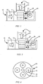
- FIG. 1 shows schematically a first pump arrangement of the invention.
- the pump has an inlet 10 and an outlet 12, and a centrifugal impeller 14 for receiving liquid from the inlet and delivering it to the outlet.
- the impeller 14 is driven by a motor 16 about an output shaft 18 of the motor which is parallel to the direction of fluid intake. The fluid is expelled by the pump perpendicularly, in conventional manner.
- an inlet valve 20 and an outlet valve 22 are provided, and these cooperate with a diaphragm 24.
- the diaphragm 24 is driven by the motor 16 to provide priming and oscillates in reciprocal manner parallel to the shaft 18 to provide the priming operation.
- the diaphragm can be integrated into the housing without taking up significant additional space and uses relatively little power.
- the pump includes an arrangement for converting rotation of the output shaft 18 into reciprocating movement for driving the diaphragm 24. This is not shown in detail in Figure 1.
- Figure 1 shows schematically the diaphragm sealing with the outer casing of the pump at its outer edge and fixed axially at the outer edge.
- An inner opening in the diaphragm seals around the shaft 18 and moves backwards and forwards.
- the diaphragm does not rotate with the shaft, so that the interface between the inner opening of the diaphragm 24 and the shaft 18 must provide sealing for both rotational and sliding movement of the diaphragm relatively to the shaft.
- the impeller 14 does not seal within the pump casing so that gas can pass around the impeller to the diaphragm.
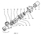
- the means for converting rotation of the output shaft 18 of the motor 16 comprises a pair of cam wheels 30, 32.
- Each of these cam wheels comprises a substantially flat plate which rotates about the output shaft 18 (or an extension piece 18a).
- the two cam members face each other and have lobes 31, 33 on their inner faces.
- the lobes in one of the cam members are aligned with the recesses between lobes in the other, so that a fixed distance is provided between the profiles of the faces of the cam wheels which face each other.
- each cam wheel 30,32 there are four cam lobes disposed around the periphery of each cam wheel 30,32.
- Four drive pins 36 are sandwiched between the cam wheels, and as the cam wheels rotate, these pins move forwards and backwards parallel to the axis of the motor output shaft 18.
- the drive pins 36 are rotationally fixed as will become clearer below.
- the diaphragm arrangement 24 is positioned between the cam wheels, and each drive pin 36 is for driving an associated diaphragm.
- the diaphragm is held between members 40, 42 and an end plate 44 is provided having openings 46 which ensure the stability of the drive pins 36 as they move backwards and forwards.
- the elements 24,40,42,44 can be a single moulded article, for example a two-shot moulded article. A rigid plastic is used for most of the article, and a more flexible plastic is used for the deformable membrane parts of the diaphragm arrangement.
- the diaphragm ring 24 seals with the inside of the pump casing.
- the members 40, 42 are a tight fit in the pump casing, so that none of these components are able to rotate.
- the cam wheels 30, 32 are rotationally keyed to the output shaft 18 (or 18a) so that they rotate with the motor output and cause the pins 36 to move backwards and forwards.
- Figure 4 shows in greater detail the diaphragm arrangement 24. It comprises a rigid ring 50 into which are moulded flexible individual diaphragms 52 each having an opening 54 for engaging with an associated drive pin 36.
- the drive pin may have a nut 60 and thread for clamping the pin to the diaphragm 52.
- a central opening 56 allows the passage of the motor shaft 18, and a lip seal 58 (shown in Figure 3) is mounted within the opening 56 around the output shaft 18.
- the ring 50 is thus mounted a fixed axial position along the shaft 18, and this makes sealing of the ring around the output shaft easier.
- the diaphragms 52 are provided in a circle around the central axis, and they are controlled (synchronously) by the drive pins, so that they all pump in parallel.
- the overall pump dimensions are kept to a minimum, for example by having the centrifugal impeller 14 and one of the cam wheels 30 defined as a single body.
- the pump arrangement of Figure 3 is also easy to assemble.
- the first cam wheel 33 is placed over the motor output shaft 18 (or 18a), then the diaphragm arrangement - which may be a single two-shot moulded article combining parts 40,24,42,44 - is placed over the top.
- the drive pins 36 and central lip seal will already be assembled to the diaphragm arrangement.
- the second cam wheel 30 is then placed over the top, and the keying with the shaft 18 (or 18a) will ensure that it adopts the correct orientation. Finally, the housing with the valves is placed over the top.
- the speed of rotation of the output shaft 18 will determine the speed of oscillation of the diaphragms 52.
- a compromise thus needs to be found between the rotational speed of the centrifugal impeller 14 and the oscillation speed of the diaphragms 52. If this compromise cannot be found, the output shaft of the motor can comprise first and second shaft members, a first shaft member for rotating the impeller at a first angular speed, and a second shaft member for rotating the cam wheels at a second, lower, angular speed.
- An inner output shaft 60 extends to the centrifugal impeller 14 and an outer shaft 62 is used for driving the diaphragm 24.
- Figure 6 shows a device of the invention for this purpose.
- the device has a rotary input shaft 70, which is connected to the output shaft of the motor in the pump.
- An output shaft 72 is slidable axially with respect to the input shaft, for example they may be separate components with a space between them.
- the input and output shafts 70, 72 are aligned on the same axis, providing a compact arrangement.
- An annular cam member 74a, 74b is mounted around the output shaft 72 and defines a cam channel which varies in axial position around the annular cam member.
- the cam member 74 rotates with respect to the output shaft 72.
- a linkage 76 is provided for fixing the axial position of the output shaft 72 with respect to the cam channel.
- the linkage 76 comprises two wheels 78 on the ends of an axle 80.
- the wheels 78 follow the channel defined between the cam members 74a, 74b.
- the wheels 78 thus move backwards and forwards, and this movement is transferred to the output shaft 72.
- the shaft 72 cannot rotate, for example rotation is prevented by the device to which the output shaft 72 is connected by the shaped end 82.
- the input shaft 70 rotates the housing 84, which causes rotation of the cam members 74a, 74b by virtue of the coupling pins 86 which engage in slots in the cam members 74a, 74b.
- cam member may be a single component with a channel formed for receiving a drive pin. Relative rotation between the drive pin and the cam member will then cause relative axial movement.
- the reciprocating movement of the output shaft 72 can then be used in a pump of the invention to drive the diaphragm.
- the arrangement of Figure 6 may provide the outer shaft 62 of Figure 5, and the inner shaft 60 may pass through the arrangement of Figure 6, through a bore on the central axis and which passes through the shafts 70, 72. This central bore is not shown in Figure 6.
- the diaphragm is operated at all times when the motor is running. Whilst the operation of the diaphragm will not interfere with the operation of the centrifugal pump, it may reduce efficiency slightly.
- a clutch can be provided in the path of the outer shaft 62.
- the clutch can operate automatically in dependence on the direction of rotation, so that priming is carried out by driving the motor in one direction (with the centrifugal impeller operating in reverse), and pumping is carried out by driving the motor in the opposite direction.
- valves 20,22 may be used, for example vane valves.
- the pump of the invention is suitable for any liquid, including liquids carrying some solid matter. It is well known that centrifugal pumps are suitable for pumping liquids with solid matter, for example for use in electrically pumped toilets, for example for marine applications.
Landscapes
- Engineering & Computer Science (AREA)
- Mechanical Engineering (AREA)
- General Engineering & Computer Science (AREA)
- Reciprocating Pumps (AREA)
- Structures Of Non-Positive Displacement Pumps (AREA)
Abstract
Description
Claims (14)
- A self-priming centrifugal pump comprising:an inlet and an outlet; anda centrifugal impeller for receiving liquid from the inlet and delivering it to the outlet, the impeller being driven by a motor, wherein the pump further comprises:an inlet valve and an outlet valve; anda diaphragm arrangement, the diaphragm arrangement being driven by the motor to provide priming.
- A pump as claimed in claim 1, wherein the impeller is rotated about an output shaft of the motor.
- A pump as claimed in claim 2, wherein the diaphragm arrangement is driven for reciprocating movement parallel to the output shaft.
- A pump as claimed in claim 3, further comprises means for converting rotation of the output shaft into reciprocating movement for driving the diaphragm.
- A pump as claimed in claim 4, wherein the means for converting comprises a pair of cam wheels rotating about the output shaft, at least one diaphragm drive element being sandwiched between the cam wheels, the drive element being coupled to an associated diaphragm.
- A pump as claimed in claim 5, wherein a plurality of diaphragm drive elements are provided, and wherein a plurality of associated diaphragms are mounted in a carrier, the carrier being mounted around the output shaft but not rotating with the output shaft.
- A pump as claimed in 5 or 6, wherein the output shaft of the motor comprises first and second shaft members, a first shaft member for rotating the impeller at a first angular speed, and a second shaft member for rotating the cam wheels at a second, lower, angular speed.
- A pump as claimed in claim 7, wherein the first and second shaft members are concentric about a common axis.
- A pump as claimed in claim 4, wherein the means for converting comprises
a diaphragm drive shaft slidable axially with respect to the motor output shaft;
an annular cam member mounted around the diaphragm drive shaft and defining a cam channel which varies in axial position around the annular cam member, the cam member rotating with respect to the diaphragm drive shaft;
a linkage for fixing the axial position of the diaphragm drive shaft with respect to the cam channel. - A pump as claimed in claim 9, wherein the output shaft of the motor comprises first and second shaft members, a first shaft member for rotating the impeller at a first angular speed, and a second shaft member for rotating the cam member with respect to the diaphragm drive shaft at a second, lower, angular speed.
- A pump as claimed in claim 10, wherein the first and second shaft members are concentric about a common axis.
- A pump as claimed in claim 10 or 11, wherein the second shaft member is provided with a clutch, so that the means for converting can turned on or off.
- A pump as claimed in claim 12, wherein the clutch operates automatically in dependence on the direction of rotation.
- A pump as claimed in any preceding claim, wherein the inlet and outlet valves comprise vane valves.
Applications Claiming Priority (2)
| Application Number | Priority Date | Filing Date | Title |
|---|---|---|---|
| GB0318225 | 2003-08-04 | ||
| GB0318225A GB2404695B (en) | 2003-08-04 | 2003-08-04 | Self-priming centrifugal pump |
Publications (2)
| Publication Number | Publication Date |
|---|---|
| EP1505301A2 true EP1505301A2 (en) | 2005-02-09 |
| EP1505301A3 EP1505301A3 (en) | 2006-07-12 |
Family
ID=27799761
Family Applications (1)
| Application Number | Title | Priority Date | Filing Date |
|---|---|---|---|
| EP04254164A Withdrawn EP1505301A3 (en) | 2003-08-04 | 2004-07-13 | Self-priming centrifugal pump |
Country Status (3)
| Country | Link |
|---|---|
| US (1) | US7037086B2 (en) |
| EP (1) | EP1505301A3 (en) |
| GB (1) | GB2404695B (en) |
Cited By (2)
| Publication number | Priority date | Publication date | Assignee | Title |
|---|---|---|---|---|
| EP1911976A3 (en) * | 2006-10-12 | 2009-12-02 | ITT Manufacturing Enterprises, Inc. | Self-priming centrifugal pump |
| CN102359450A (en) * | 2011-09-07 | 2012-02-22 | 韩杰 | Mobile lifting drainage device |
Families Citing this family (5)
| Publication number | Priority date | Publication date | Assignee | Title |
|---|---|---|---|---|
| US20080089777A1 (en) * | 2006-08-30 | 2008-04-17 | Lang John P | Self-priming adapter apparatus and method |
| WO2010030802A2 (en) | 2008-09-10 | 2010-03-18 | Pentair Pump Group, Inc. | High-efficiency, multi-stage centrifugal pump and method of assembly |
| WO2012088312A2 (en) | 2010-12-21 | 2012-06-28 | Sta-Rite Industries, Llc | Diaphragm pump and motor system and method |
| WO2014076519A1 (en) * | 2012-10-29 | 2014-05-22 | Debiotech S.A. | Extracorporeal blood treatment device |
| US10173183B2 (en) | 2014-09-11 | 2019-01-08 | Flowserve Management Company | Diaphragm pump with improved tank recirculation |
Family Cites Families (14)
| Publication number | Priority date | Publication date | Assignee | Title |
|---|---|---|---|---|
| FR776118A (en) * | 1933-07-27 | 1935-01-17 | Device for converting a reciprocating motion into a rotational motion in piston machines | |
| US2292896A (en) * | 1940-11-18 | 1942-08-11 | Capewell Mfg Company | Fluid pumping apparatus |
| US2412839A (en) * | 1944-03-28 | 1946-12-17 | Smith Julius Lamar | Centrifugal pump primer |
| US2857851A (en) * | 1955-04-29 | 1958-10-28 | Dempster Mill Mfg Company | Priming pump |
| GB804265A (en) * | 1956-08-08 | 1958-11-12 | Josef Eisele | Method of and apparatus for priming a centrifugal pump for pumping mud, sludge and liquids containing semi-solids |
| GB918798A (en) * | 1960-10-13 | 1963-02-20 | Josef Eisele | Improvements in or relating to self-priming centrifugal pumps |
| US3578880A (en) * | 1969-07-24 | 1971-05-18 | Chandler Evans Inc | Diaphragm operated priming device for centrifugal impeller pump |
| US3644061A (en) * | 1969-07-31 | 1972-02-22 | Gorman Rupp Co | Pump apparatus |
| GB1390029A (en) * | 1971-07-29 | 1975-04-09 | Lucas Industries Ltd | Fuel pumps for use in conjunction with gas turbine engines |
| US4013053A (en) * | 1975-05-02 | 1977-03-22 | Stewart-Warner Corporation | Fuel pump |
| US4035104A (en) * | 1975-09-19 | 1977-07-12 | Ingersoll-Rand Company | Self-priming centrifugal pump |
| JPH01203751A (en) * | 1988-02-08 | 1989-08-16 | Sanden Eng Kk | Power transmission device |
| GB2219958B (en) * | 1988-06-23 | 1992-09-16 | Hugh Edward Fisher | Power tool |
| US6409478B1 (en) * | 1999-02-26 | 2002-06-25 | Roper Holdings, Inc. | Vacuum-assisted pump |
-
2003
- 2003-08-04 GB GB0318225A patent/GB2404695B/en not_active Expired - Fee Related
-
2004
- 2004-07-13 EP EP04254164A patent/EP1505301A3/en not_active Withdrawn
- 2004-07-30 US US10/903,504 patent/US7037086B2/en not_active Expired - Lifetime
Cited By (3)
| Publication number | Priority date | Publication date | Assignee | Title |
|---|---|---|---|---|
| EP1911976A3 (en) * | 2006-10-12 | 2009-12-02 | ITT Manufacturing Enterprises, Inc. | Self-priming centrifugal pump |
| US8182200B2 (en) | 2006-10-12 | 2012-05-22 | Itt Manufacturing Enterprises, Inc. | Self priming pump |
| CN102359450A (en) * | 2011-09-07 | 2012-02-22 | 韩杰 | Mobile lifting drainage device |
Also Published As
| Publication number | Publication date |
|---|---|
| EP1505301A3 (en) | 2006-07-12 |
| US7037086B2 (en) | 2006-05-02 |
| GB2404695A (en) | 2005-02-09 |
| US20050111990A1 (en) | 2005-05-26 |
| GB0318225D0 (en) | 2003-09-03 |
| GB2404695B (en) | 2006-05-31 |
Similar Documents
| Publication | Publication Date | Title |
|---|---|---|
| US4153391A (en) | Triple discharge pump | |
| CN100516514C (en) | Magnetically driven gear pump | |
| US4747744A (en) | Magnetic drive gerotor pump | |
| US4747762A (en) | Fluid machine | |
| EP1911976B1 (en) | Self-priming centrifugal pump | |
| EP0743457B1 (en) | Centrifugal pump with flexible vanes priming pump | |
| US7037086B2 (en) | Self-priming centrifugal pump | |
| KR101166685B1 (en) | Pressure Recovery Mechanism using Hydrostatic Power Transmission | |
| CN106536855A (en) | Vacuum pump with eccentrically driven vane (eccentric pump design) | |
| CN100398830C (en) | liquid ring pump | |
| HK1073492A (en) | Self-priming centrifugal pump | |
| US11408415B2 (en) | Pump assemblies configured for drive and pump end interchangeability | |
| US11313371B2 (en) | Pump assemblies configured for drive and pump end interchangeability | |
| KR101785062B1 (en) | Triangular rotary pump | |
| US11614085B2 (en) | Pump assemblies configured for drive and pump end interchangeability | |
| US3582235A (en) | Rotary pump | |
| KR102654552B1 (en) | rotating positive displacement pump | |
| EP3149332B1 (en) | A rotary pump | |
| WO2002070897A3 (en) | A vane pump | |
| KR200218430Y1 (en) | Impeller Assembly for Magnet Pump | |
| KR200194391Y1 (en) | Vane pump | |
| US20070025870A1 (en) | Eccentric pump, and use thereof | |
| GB2257750A (en) | "rotary pumps" | |
| HK1110929B (en) | Self-priming centrifugal pump | |
| JP2002155854A (en) | Small pump |
Legal Events
| Date | Code | Title | Description |
|---|---|---|---|
| PUAI | Public reference made under article 153(3) epc to a published international application that has entered the european phase |
Free format text: ORIGINAL CODE: 0009012 |
|
| AK | Designated contracting states |
Kind code of ref document: A2 Designated state(s): AT BE BG CH CY CZ DE DK EE ES FI FR GB GR HU IE IT LI LU MC NL PL PT RO SE SI SK TR |
|
| AX | Request for extension of the european patent |
Extension state: AL HR LT LV MK |
|
| REG | Reference to a national code |
Ref country code: HK Ref legal event code: DE Ref document number: 1073492 Country of ref document: HK |
|
| PUAL | Search report despatched |
Free format text: ORIGINAL CODE: 0009013 |
|
| AK | Designated contracting states |
Kind code of ref document: A3 Designated state(s): AT BE BG CH CY CZ DE DK EE ES FI FR GB GR HU IE IT LI LU MC NL PL PT RO SE SI SK TR |
|
| AX | Request for extension of the european patent |
Extension state: AL HR LT LV MK |
|
| AKX | Designation fees paid | ||
| REG | Reference to a national code |
Ref country code: DE Ref legal event code: 8566 |
|
| STAA | Information on the status of an ep patent application or granted ep patent |
Free format text: STATUS: THE APPLICATION IS DEEMED TO BE WITHDRAWN |
|
| 18D | Application deemed to be withdrawn |
Effective date: 20070113 |
|
| REG | Reference to a national code |
Ref country code: HK Ref legal event code: WD Ref document number: 1073492 Country of ref document: HK |