EP1505279A2 - Fuel control for gas turbine engines - Google Patents
Fuel control for gas turbine engines Download PDFInfo
- Publication number
- EP1505279A2 EP1505279A2 EP04254434A EP04254434A EP1505279A2 EP 1505279 A2 EP1505279 A2 EP 1505279A2 EP 04254434 A EP04254434 A EP 04254434A EP 04254434 A EP04254434 A EP 04254434A EP 1505279 A2 EP1505279 A2 EP 1505279A2
- Authority
- EP
- European Patent Office
- Prior art keywords
- fmu
- eec
- memory device
- data
- supply system
- Prior art date
- Legal status (The legal status is an assumption and is not a legal conclusion. Google has not performed a legal analysis and makes no representation as to the accuracy of the status listed.)
- Granted
Links
Images
Classifications
-
- F—MECHANICAL ENGINEERING; LIGHTING; HEATING; WEAPONS; BLASTING
- F02—COMBUSTION ENGINES; HOT-GAS OR COMBUSTION-PRODUCT ENGINE PLANTS
- F02C—GAS-TURBINE PLANTS; AIR INTAKES FOR JET-PROPULSION PLANTS; CONTROLLING FUEL SUPPLY IN AIR-BREATHING JET-PROPULSION PLANTS
- F02C9/00—Controlling gas-turbine plants; Controlling fuel supply in air- breathing jet-propulsion plants
- F02C9/26—Control of fuel supply
- F02C9/28—Regulating systems responsive to plant or ambient parameters, e.g. temperature, pressure, rotor speed
Definitions
- This invention relates to a Fuel Metering Unit (FMU) for use in an aircraft gas turbine engine fuel supply system, and the invention also relates to a fuel supply system for an aircraft gas turbine engine utilising the FMU and to a method of operating the fuel supply system.
- FMU Fuel Metering Unit
- FMU fuel metering unit
- EEC Electronic Engine Controller
- FADEC Full Authority Digital Engine Controller
- the FMU is a single fuel metering valve incorporating a motor or the like for driving the valve between open and closed positions and a position transducer which supplies to the EEC signals representative of the operative position of the valve.
- the FMU will include other control components in association with the metering valve such as, for example, a Pressure Drop Regulator and Spill Valve (PDSV) which controls the pressure drop across the metering orifice of the metering valve, and, a Pressure Raising and Shut Off Valve (PRSOV) which ensures a minimum system fuel pressure and can disconnect the engine from the metering valve when appropriate.
- PDSV Pressure Drop Regulator and Spill Valve
- PRSOV Pressure Raising and Shut Off Valve
- the FMU as described above may be an integral part of the fuel pumping arrangement of the fuel supply system.
- the EEC is programmed with a predetermined fuel control law to which the FMU adheres.
- the fuel control law will contain a predetermined table of FMU input signals to be supplied to the metering valve to vary the opening of the metering valve, so as to achieve predetermined flow values of the fuel supplied from the FMU to the engine.
- the FMU is initially subjected to a detailed and rigorous calibration procedure during and after assembly, and before the FMU enters service. The calibration procedure is used to adjust the metering valve, and other components of the FMU when present, so that for a given fuel flow demand signal from the EEC a predetermined output of fuel from the FMU is achieved.
- the calibration procedure for the FMU is time-consuming and therefore expensive.
- calibration involves making adjustments, accurately shimming position sensors and springs, and may involve repeated assembly and disassembly of the FMU.
- every FMU which is manufactured to suit a particular application must go through the same calibration process so that after calibration its performance characteristics are as close as possible to the performance characteristics of every other calibrated FMU for use in that application, and to the fuel control law stored within the EEC.
- metering valve position sensors which are all produced to a similar high level of accuracy.
- the devices which drive the metering element of the metering valve to set the opening of the valve and also the other valves associated with the metering process.
- Such accurately produced components are inherently expensive.
- a further disadvantage of a conventional fuel control arrangement is that it is costly to make in-service changes. If a change is made to a conventional FMU design after the unit has entered service and this change affects the basic flow versus metering valve position calibration, it is very expensive to change the fuel control law software in all the in-service EECs. Also there would be the potential to miss-match EECs having the amended control law with pre-modification standard FMUs. It is therefore usual to implement such design changes by modifying the FMU metering valve metering profile, so that modified FMUs will obey the unchanged fuel control law, and this can often be difficult and expensive to achieve.
- a fuel metering unit for an aircraft gas turbine engine, incorporating a memory device for storing data relevant to at least one of the performance, the identification, the health and the service life of that FMU, and an electrical connection arrangement whereby data can be read from and/or written to said memory device in use by an associated electronic engine controller.
- FMU fuel metering unit
- Performance data includes data related to the calibration of the FMU, that is a fuel control, or fuel flow, law which relates fuel flow through the FMU to the operative position of flow control components of the FMU;
- Identity data includes a unique serial number containing inter alia manufacturing, specification, and build identifiers;
- Health data includes fault codes and prognostic data relating for example to pump leakage and/or filter pressure drops;
- Service data includes run hours and maintenance history.
- the memory device stores calibration data of the FMU.
- the memory device stores service data of the FMU.
- said service data includes fault codes written to the FMU by the associated EEC and readable from the memory device during maintenance of the FMU remote from the EEC.
- said service data comprises the cumulative hours of operation of the FMU written to the memory device during operation of the FMU, by the associated EEC, and readable from the memory device during maintenance of the FMU remote from the EEC.
- the memory device additionally stores a code identifying its FMU.
- an aircraft gas turbine engine fuel supply system incorporating an FMU as specified in any one of the preceding paragraphs and an EEC so connected to the FMU as to be able to read from and/or write to said memory device.
- said memory device stores calibration data of the FMU and can be read by the EEC.
- the EEC fuel control law is updated by the calibration data stored in the memory device of the associated FMU each time the fuel supply system is initialised.
- the memory device of the FMU also stores identification data of the FMU and upon initialisation of the fuel supply system the EEC first checks that the associated FMU is the one in respect of which its fuel control law was previously updated, and if the FMU is recognised then the EEC utilises the fuel control law stored therein from a previous initialisation, but in the event that the FMU is not recognised then the EEC reads the calibration data stored in the memory device of the FMU and uses the data read from the memory device to update its fuel control law.
- the EEC writes service data to the memory device of its associated FMU.
- an aircraft gas turbine engine fuel metering unit comprising assembling the FMU from components whose individual characteristics allow the assembled FMU to have operating characteristics falling within a predetermined band of acceptable characteristics, incorporating a memory device into the FMU, testing to establish the FMU operating characteristics, and storing data representative of those characteristics in the memory device of the FMU to be read by an associated electronic engine controller (EEC) in use to modify the control regime of that EEC to suit that FMU.
- FMU gas turbine engine fuel metering unit
- the data stored in the memory device is established by testing during and/or after assembly of the FMU.
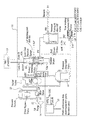
- the engine fuel supply system includes a Fuel Metering Unit (FMU) 11 comprising the components shown within the broken line boundary in the drawing.
- FMU Fuel Metering Unit
- the FMU comprises only a fuel metering valve 12 which can be operated by an associated EEC or Full Authority Digital Engine Controller (FADEC) 13 to meter the quantity of fuel supplied from a fuel supply 14 to the burners 15 of an associated gas turbine engine.
- FADEC Full Authority Digital Engine Controller
- the FMU will include other components as shown in the drawing, including a Pressure Drop Regulator and Spill Valve (PDSV) and a Pressure Raising and Shut Off Valve (PRSOV) as shown at 16 and 17 respectively in the drawing.
- PDSV Pressure Drop Regulator and Spill Valve
- PRSOV Pressure Raising and Shut Off Valve
- the high pressure pump 23 is shown as an element separate from the FMU 11, in some applications the pump may be physically combined with the FMU.
- the PDSV 16 controls the pressure drop across the metering profile or orifice of the metering valve 12, and the PRSOV 17 ensures that there is a minimum system fuel pressure before fuel is supplied to the burners 15, and can, in appropriate circumstances, be used to disconnect the burners 15 from the metering valve 12.
- the exact architecture of the FMU is not of particular relevance to the present invention, and the internal constituents of the FMU may differ dependent upon the application for which the FMU is designed. However, irrespective of the nature of the FMU, in accordance with the various aspects of the present invention, the FMU includes a memory device 18 for storing data associated with the FMU.
- the memory device may take a number of forms, but generally will be a solid state memory device, conveniently an EEPROM.
- the memory device is incorporated within the structure of the FMU, and so is integral to the FMU. More particularly, the FMU will include an external housing having an input port through which fuel enters the FMU, and an output port from which fuel exits the FMU to the burners 15.
- the memory device 18 is within, or secured to, the housing of the FMU.
- the FMU effectively includes the fuel pump and the memory device 18 may in such applications be located on the pump casing. Thus additionally pump fault codes and other data related to the pump may be stored within the unit.
- the stored data may be data related to or representative of the health of the unit or of a component part of the unit.
- monitoring pressure drop across a fuel filter and such prognostic data is an example of "Health" data which could be stored in the memory device 16 of the present unit.
- the metering valve 12 of the FMU incorporates a drive device 12a for moving the metering element of the metering valve 12 to adjust the metering orifice of the valve, and thus to adjust the fuel flow through the valve, in accordance with command signals from the EEC 13. Additionally the metering valve includes a position sensor 12b which supplies position signals from the metering valve 12 to the EEC 13 identifying the physical position of the metering element of the valve 12.
- the device 12a is an electrically operated stepper motor and the position sensor 12b is a Rotary Variable Differential Transformer (RVDT), the valve 12 being a rotary valve.
- RVDT Rotary Variable Differential Transformer
- the metering valve 12 will be a linear valve and the RVDT can be replaced by an LVDT, the stepper motor 12a being replaced by a linear actuator, either an electrically powered linear actuator, or an hydraulically powered linear actuator controlled by an electrically controlled valve.
- the accompanying drawing shows that the RVDT is a dual-channel device in that effectively it is two RVDT's operating in parallel, each supplying data along a respective "lane" to the EEC.
- the memory device 18 also connects into the data buses constituting the two lanes identified in the drawing as lane A and lane B and so is connected to the EEC when the FMU is in use. Two memory devices acting in parallel may be provided to enhance electrical redundancy if required.
- the EEC holds the fuel control law which determines the position to which the metering element of the valve 12 must be moved from its current position to achieve a predetermined fuel flow through the burners 15.
- This law is predetermined, and is stored in the EEC and is a common law used to control all FMUs which may be used in that application.
- the FMU is calibrated during and after assembly, (and after some maintenance operations) so that its performance conforms to the law stored in the EEC in that it will provide a predetermined fuel output when its metering element is moved to a predetermined position in response to a corresponding command signal from the EEC. All other FMUs for use in the same application will be similarly calibrated, and where the FMU incorporates dual-channel technology then the calibration will ensure that the position signals transmitted along both lanes are substantially identical.
- a typical FMU will include several components which require calibration and the necessary calibration adjustments, each of which may affect the calibration of another, will include, adjustment of a low flow adjuster, a pressure drop spring pre-load adjustment, and LVDT datum adjustments.
- the provision of such calibration items and their inter-relationship is well known to the skilled aircraft fuel systems engineer. Such an engineer will recognise that the inter-action of these adjustments will include, for example, that adjustment of the pressure drop pre-load to achieve a predetermined flow in one FMU operating condition may require re-setting of the LVDT datum adjustment to compensate for the effect on flow of the pre-load adjustment, in other FMU operating conditions.
- the calibration of an FMU, even a relatively simple FMU, is an iterative process which is both time consuming and expensive.
- FMUs can be assembled from a standard range of components so producing FMUs whose operating characteristics lie somewhere within a relatively broad range of acceptable characteristics.
- Each assembled FMU can be tested during and/or after assembly and its "calibration characteristics" can be stored in the dedicated memory device of that FMU and then, when the FMU is in use, the stored data can be supplied to the associated EEC to modify or replace the fuel control law which the EEC uses to operate the FMU in use. It will be recognised therefore that it is necessary only to ensure that FMUs are assembled from components whose individual accuracy is sufficient to ensure that the assembled FMU will have characteristics lying within the broad acceptable band of characteristics. It will be understood that only FMUs within a narrow part of the broad acceptable band would be capable of use with the relevant EEC if the flow law of that EEC was not replaced or modified by the calibration data stored in the memory device of the FMU.
- the memory device 18 stores calibration data relevant to the FMU 11.
- calibration data relevant to that particular FMU.
- the fuel control law of the FMU (the fuel output for a series of positions of the metering element) is determined by testing, and it is this data, conveniently referred to as calibration data, which is stored in the memory device 18. It will be possible to produce a testing apparatus which determines the operating characteristics of the FMU across its full working range and stores the data resulting from this testing directly in the memory device 18.
- each FMU will in effect carry, in its respective memory device 18, the fuel control law associated with that FMU, and the fuel control law of one FMU for use in a particular application may well differ from the fuel control law of an equivalent FMU for use in the same application.
- the use of a memory device in each FMU storing the particular calibration data of that FMU allows the EEC with which the FMU is associated in use to be "updated” to utilize a fuel flow law specific to that FMU.
- the EEC When the FMU is introduced into the fuel supply system, and the fuel supply system is first initialised then the EEC immediately interrogates the memory device 18 of the associated FMU and reads from the memory device 18 the stored data to provide a fuel control law relevant to that FMU. That FMU's fuel control law then is used as the fuel control law which the EEC utilises to control the fuel supply system.
- the EEC will read the fuel control law from the memory device 18 of the replacement FMU and will use that fuel control law to replace the stored fuel control law of the previous FMU.
- the two FMUs are not identical, no individual calibration is needed since the fuel control law which the EEC uses is the fuel control law derived from the FMU memory device, and not a standard fuel control law to which all FMUs must conform, as is currently the case.
- the EEC can interrogate the memory device 18 so that the fuel control law of the EEC is checked, and if necessary updated, each time the EEC is initialised, or even at predetermined intervals during an operational period of the fuel supply system.
- the memory device 18 will also store identification data, for example a unique identifying serial number, relevant to the FMU.
- the EEC upon EEC initialisation, the EEC will check that the fuel control law which it has stored is the fuel control law of the FMU to which it is presently connected, and it will achieve this by interrogation of the identity data of the memory unit 18. If the EEC determines that the identity of the law which is stored does not match the identity of the FMU then it will read the fuel control law from the device 18 and use the newly read law to replace the existing law stored in the EEC.
- each FMU allows the implementation of other advantages.
- the maintenance operative has no way of knowing the service life of the FMU, or details of any faults which may have been detected in the operation of the FMU during its previous service life.
- the operative can obtain this information either by a download of data stored in the associated EEC or by consulting a manual maintenance log, but since both of these may well be in the associated aircraft, then the maintenance operative must obtain the information when he removes the FMU from service for maintenance.
- the memory device can store fault code information relevant to operational faults of the FMU detected by the EEC during the previous service interval, and/or the memory device can store data identifying the length of time during which the FMU has been in service. Since this data is carried by the memory device of the FMU, then when an FMU is removed from an engine control system, to a location remote from the EEC, for maintenance, the relevant data can be obtained from the FMU by the maintenance operative, using a memory device reader at the maintenance location, without the need to refer back to a manual log, or the EEC of the fuel supply system.
- a maintenance operative can, if desired, be provided with a portable reader to permit the memory device to be read with the FMU in situ if maintenance of the FMU is to be performed without removing the FMU from the engine fuel system if it is inconvenient to read the device 18 using the EEC.
- the memory device 18 cannot be written to by the EEC, and carries only the calibration data of the FMU.
- the memory device 18 can be written to by the EEC, and the memory device carries only service data relating to the FMU written thereto by the engine controller, and identification data identifying the FMU.
- the service data may simply be data identifying the length of time that the FMU has been in operation, or alternatively may simply be fault codes indicative of faults detected by the engine controller during a previous operational period.
- the memory 18 will contain FMU calibration data and will be capable of being written to by the associated engine controller to store EEC and FMU identification data and FMU service data.
- the ability to signal the identity of the FMU to the EEC is advantageous in that it allows the EEC to confirm, for example after service replacement of parts, the FMU in situ is suitable for operation in conjunction with the software release which is being run by the EEC.
- the FMU carries with it a memory device 18.
- the construction of the remainder of the fuel supply system is not of particular importance to the invention.
- fuel from a supply 14 is pumped by a low pressure pump 21 through a main filter 22 to the inlet of a high pressure pump 23.
- the output from the high pressure pump 23 is fed into the FMU 11 where it first passes through a flow wash filter for supply to the input of the metering valve 12.
- a main filter by-pass arrangement 23 allows fuel to by-pass the main filter in the event that the filter becomes blocked, and it will be recognised by the skilled man that the arrangement for supplying fuel to the FMU 11 can take a number of different forms to suit different applications.
- the solid state memory device 18 (conveniently an EEPROM package) will be positioned on a cool region the FMU (or integrated FMU/pumping arrangement) in order to maintain an acceptable operating temperature.
- a convenient EEPROM for the memory device 18 is a serial EEPROM, for example an "Atmel 24C16".
- the currently preferred EEPROM (“Atmel 24C16”) provides 16 kbits (2k x 8 bytes) of data storage. This amount of storage readily accommodates the storage of dual channel data relating to the calibration of the channels of the FMU and also the storage of fault codes, FMU and EEC identification data, and FMU operating hours.
Landscapes
- Engineering & Computer Science (AREA)
- Chemical & Material Sciences (AREA)
- Combustion & Propulsion (AREA)
- Mechanical Engineering (AREA)
- General Engineering & Computer Science (AREA)
- Combined Controls Of Internal Combustion Engines (AREA)
- Electrical Control Of Air Or Fuel Supplied To Internal-Combustion Engine (AREA)
- Control Of The Air-Fuel Ratio Of Carburetors (AREA)
Abstract
Description
"Identification" data includes a unique serial number containing inter alia manufacturing, specification, and build identifiers;
"Health" data includes fault codes and prognostic data relating for example to pump leakage and/or filter pressure drops;
"Service" data includes run hours and maintenance history.
Claims (16)
- An aircraft gas turbine engine fuel metering unit (FMU) characterised by incorporating a memory device (18) for storing data relevant to at least one of the performance, the identification, the health and the service life of that FMU, and an electrical connection arrangement whereby data can be read from and/or written to said memory device in use by an associated electronic engine controller.
- A fuel metering unit as claimed in claim 1 characterised in that the memory device contains stored performance data in the form of calibration data of the FMU.
- A fuel metering unit as claimed in claim 2 characterised in that, the memory device additionally stores service data of the FMU.
- A fuel metering unit as claimed in any one of the preceding claims characterised in that said service data includes fault codes written to the FMU by the associated EEC and readable from the memory device during maintenance of the FMU remote from the EEC.
- A fuel metering unit as claimed in any one of the preceding claims characterised in that said service data comprises the cumulative hours of operation of the FMU written to the memory device during operation of the FMU, by the associated EEC, and readable from the memory device during maintenance of the FMU remote from the EEC.
- A fuel metering unit as claimed in any one of claims 2 to 5 characterised in that the memory device additionally stores a code identifying its FMU.
- An aircraft gas turbine engine fuel supply system characterised by incorporating an FMU as specified in any one of the preceding claims and an electronic engine controller (EEC) so connected to the FMU as to be able to read from and/or write to said memory device.
- An engine fuel supply system as claimed in claim 7 characterised in that said memory device contains stored calibration data of the FMU and can be read by the EEC.
- A method of operating an aircraft gas turbine engine fuel supply system as claimed in claim 8 characterised in that the calibration data stored by the memory of the FMU is read by the EEC when the fuel supply system is initialised and is used by the EEC as the fuel control law for operation of the FMU.
- A method of operating an engine fuel supply system as claimed in claim 9 characterised in that the EEC fuel control law is updated by the calibration data stored in the memory device of the associated FMU each time the fuel supply system is initialised.
- A method of operating an engine fuel supply system as claimed in claim 9 characterised in that, the memory device of the FMU also stores identification data of the FMU and upon initialisation of the fuel supply system the EEC first checks that the associated FMU is the one in respect of which its fuel control law was previously updated, and if the FMU is recognised then the EEC utilises the fuel control law stored therein from a previous initialisation, but in the event that the FMU is not recognised then the EEC reads the calibration data stored in the memory device of the FMU and uses the data read from the memory device to update its fuel control law.
- A method of operating an engine fuel supply system as claimed in any one of claims 9 to 11 characterised in that during operation the EEC writes service data to the memory device of its associated FMU.
- A method of operating an engine fuel supply system of the kind claimed in claim 7 characterised by the EEC writing service data to the memory device of the FMU, and reading said data from the FMU during maintenance of the FMU while it is remote from the EEC.
- A method of operating an engine fuel supply system as claimed in claim 13 characterised in that said service data includes one of FMU/EEC fault codes, and, duration of operation of the FMU.
- A method of manufacturing an aircraft gas turbine engine fuel metering unit (FMU) characterised by assembling the FMU from components whose individual characteristics allow the assembly of an FMU having operating characteristics falling within a predetermined band of acceptable characteristics, incorporating a memory device into the FMU, testing to establish the FMU operating characteristics, and storing data representative of those characteristics in the memory device of the FMU to be read by an associated electronic engine controller (EEC) in use to modify the control regime of that EEC to suit that FMU.
- A method as claimed in claim 15 characterised in that the data stored in the memory device is established by testing during and/or after assembly of the FMU.
Applications Claiming Priority (2)
| Application Number | Priority Date | Filing Date | Title |
|---|---|---|---|
| GBGB0317394.5A GB0317394D0 (en) | 2003-07-25 | 2003-07-25 | Engine fuel control |
| GB0317394 | 2003-07-25 |
Publications (3)
| Publication Number | Publication Date |
|---|---|
| EP1505279A2 true EP1505279A2 (en) | 2005-02-09 |
| EP1505279A3 EP1505279A3 (en) | 2005-11-30 |
| EP1505279B1 EP1505279B1 (en) | 2008-03-12 |
Family
ID=27772632
Family Applications (1)
| Application Number | Title | Priority Date | Filing Date |
|---|---|---|---|
| EP04254434A Expired - Lifetime EP1505279B1 (en) | 2003-07-25 | 2004-07-23 | Fuel control for gas turbine engines |
Country Status (5)
| Country | Link |
|---|---|
| US (1) | US7204076B2 (en) |
| EP (1) | EP1505279B1 (en) |
| AT (1) | ATE389104T1 (en) |
| DE (1) | DE602004012358T2 (en) |
| GB (1) | GB0317394D0 (en) |
Cited By (4)
| Publication number | Priority date | Publication date | Assignee | Title |
|---|---|---|---|---|
| EP1903416A2 (en) | 2006-09-19 | 2008-03-26 | Goodrich Control Systems Limited | Rotary metering valve arrangement |
| EP2000779A2 (en) | 2007-05-25 | 2008-12-10 | Goodrich Control Systems Ltd | Fault diagnositics |
| US7822576B2 (en) | 2005-12-16 | 2010-10-26 | Rolls-Royce Plc | Engine health monitoring |
| EP3572646A1 (en) * | 2018-05-22 | 2019-11-27 | Hamilton Sundstrand Corporation | Calibration systems based on encoded images |
Families Citing this family (33)
| Publication number | Priority date | Publication date | Assignee | Title |
|---|---|---|---|---|
| GB0323887D0 (en) * | 2003-10-11 | 2003-11-12 | Goodrich Control Sys Ltd | Pump health monitoring |
| GB0522991D0 (en) * | 2005-11-11 | 2005-12-21 | Goodrich Control Sys Ltd | Fuel system |
| US8291886B2 (en) * | 2007-02-12 | 2012-10-23 | Honeywell International Inc. | Actuator flow compensated direct metering fuel control system and method |
| GB0705850D0 (en) * | 2007-03-27 | 2007-05-02 | Goodrich Control Sys Ltd | Fuel system |
| US20080272915A1 (en) * | 2007-05-04 | 2008-11-06 | Pratt & Whitney Canada Corp. | Equipment monitoring system and method |
| GB0709723D0 (en) | 2007-05-22 | 2007-06-27 | Goodrich Control Sys Ltd | Temperature sensing |
| US8166765B2 (en) * | 2008-10-15 | 2012-05-01 | Woodward, Inc. | Fuel delivery and control system including a variable displacement actuation pump supplementing a fixed displacement main pump |
| US8302406B2 (en) * | 2008-10-15 | 2012-11-06 | Woodward, Inc. | Fuel delivery and control system including a positive displacement actuation pump with a variable pressure regulator supplementing a fixed displacement main fuel pump |
| US8185260B2 (en) * | 2009-02-12 | 2012-05-22 | Honeywell International Inc. | Prognostic and health management accuracy maintenance system and method |
| GB0908113D0 (en) * | 2009-05-12 | 2009-06-24 | Goodrich Control Sys Ltd | Metering valve control |
| DE102009021918B4 (en) * | 2009-05-19 | 2016-04-07 | Abb Technology Ag | positioner |
| US8572985B2 (en) * | 2009-06-26 | 2013-11-05 | Pratt & Whitney Canada Corp. | Air filtration system for gas turbine engine pneumatic system |
| US8424285B2 (en) * | 2009-07-31 | 2013-04-23 | Hamilton Sundstrand Corporation | Cooling system for electronic device in a gas turbine engine system |
| FR2966518B1 (en) * | 2010-10-25 | 2012-11-30 | Snecma | CONTROL OF A FUEL ASSAY DEVICE FOR TURBOMACHINE |
| US10266034B2 (en) | 2011-06-16 | 2019-04-23 | Hamilton Sundstrand Corporation | Heat pump for supplemental heat |
| FR2986567B1 (en) * | 2012-02-08 | 2015-12-04 | Eurocopter France | METHOD FOR MONITORING AN ENGINE AND DEVICE |
| US10041497B2 (en) * | 2012-05-01 | 2018-08-07 | Eaton Intelligent Power Limited | Pressure compensation control of a fixed displacement pump in a pumping and metering system and associated method |
| US8550131B1 (en) | 2013-01-02 | 2013-10-08 | Liquid Squeeze, LLC | Liquid dispensing device, system and method |
| FR3019225B1 (en) * | 2014-03-27 | 2018-06-22 | Safran Helicopter Engines | METHOD FOR DETECTING FAILURE OF A FIRST TURBOMOTOR OF A BIMOTOR HELICOPTER AND CONTROL OF THE SECOND TURBOMOTOR, AND CORRESPONDING DEVICE |
| FR3028245B1 (en) * | 2014-11-06 | 2019-05-24 | Airbus Operations | FUEL SUPPLY CIRCUIT OF AN AIRCRAFT |
| US9831171B2 (en) * | 2014-11-12 | 2017-11-28 | Infineon Technologies Ag | Capacitors with barrier dielectric layers, and methods of formation thereof |
| US10428742B2 (en) | 2016-06-07 | 2019-10-01 | General Electric Company | Fuel delivery system and method for a gas turbine engine |
| US10228670B2 (en) | 2016-12-15 | 2019-03-12 | Woodward, Inc. | Characterization using multiplexed resistance reading |
| FR3078551B1 (en) * | 2018-03-05 | 2020-02-28 | Safran Aircraft Engines | ANTICIPATIVE CONTROL OF A FUEL SUPPLY CIRCUIT OF A TURBOMACHINE |
| US11513033B2 (en) | 2019-02-21 | 2022-11-29 | Rolls-Royce Corporation | Gas turbine engine system with health monitoring of fuel pump condition |
| US20210285384A1 (en) * | 2020-03-16 | 2021-09-16 | Hamilton Sundstrand Corporation | High accuracy fuel system |
| US11933182B2 (en) | 2020-03-24 | 2024-03-19 | Pratt & Whitney Canada Corp. | Multi-channel multi-range transducer |
| FR3109800B1 (en) | 2020-05-04 | 2022-04-01 | Safran Aircraft Engines | System and method for controlling an engine metering valve |
| US20230039760A1 (en) * | 2021-08-04 | 2023-02-09 | Pratt & Whitney Canada Corp. | System and method for monitoring life limit of engine components |
| US11859564B2 (en) | 2022-02-18 | 2024-01-02 | Hamilton Sundstrand Corporation | Smart fuel supply system |
| US12345211B2 (en) | 2023-08-21 | 2025-07-01 | Rolls-Royce North American Technologies, Inc. | Uncommanded or uncontrollable high thrust detection and mitigation |
| US12258911B2 (en) | 2023-08-21 | 2025-03-25 | Rolls-Royce Corporation | Fuel unit health monitoring system |
| US20250328156A1 (en) * | 2024-04-22 | 2025-10-23 | Hamilton Sundstrand Corporation | Fuel system with boosted and cooled variable displacement main fuel pump and electromechanical actuators |
Family Cites Families (12)
| Publication number | Priority date | Publication date | Assignee | Title |
|---|---|---|---|---|
| GB1523275A (en) | 1974-08-20 | 1978-08-31 | Cav Ltd | Digital control system for a gas turbine engine |
| US4487181A (en) | 1982-04-03 | 1984-12-11 | Lucas Industries Public Limited Company | Fuel supply system for an internal combustion engine |
| US5168447A (en) * | 1983-12-27 | 1992-12-01 | The Boeing Company | Engine trim control unit |
| GB8730187D0 (en) * | 1987-12-24 | 1988-02-03 | Rolls Royce Plc | Overspeed limiter for gas turbine aeroengine |
| US5212943A (en) * | 1991-10-08 | 1993-05-25 | Sundstrand Corporation | Reduced thermal stress turbine starting strategy |
| US5357741A (en) * | 1992-05-01 | 1994-10-25 | Dresser-Rand Company | NOx and CO control for gas turbine |
| US5265576A (en) | 1993-01-08 | 1993-11-30 | Stanadyne Automotive Corp. | Calibration system for electrically controlled fuel injection pump |
| US5575264A (en) | 1995-12-22 | 1996-11-19 | Siemens Automotive Corporation | Using EEPROM technology in carrying performance data with a fuel injector |
| DE19851797A1 (en) * | 1997-11-12 | 1999-05-20 | Bosch Gmbh Robert | Electric circuit for storing and reading out technical data of fuel metering system in motor vehicle IC engine |
| DE10007691B4 (en) | 2000-02-19 | 2006-10-26 | Robert Bosch Gmbh | Method and device for storing and / or reading data from a fuel metering system |
| US6675570B2 (en) | 2000-06-15 | 2004-01-13 | Argo-Tech Corporation | Low-cost general aviation fuel control system |
| JP3941853B2 (en) | 2000-12-04 | 2007-07-04 | 愛三工業株式会社 | Fuel injection control device |
-
2003
- 2003-07-25 GB GBGB0317394.5A patent/GB0317394D0/en not_active Ceased
-
2004
- 2004-07-23 AT AT04254434T patent/ATE389104T1/en not_active IP Right Cessation
- 2004-07-23 US US10/897,644 patent/US7204076B2/en not_active Expired - Lifetime
- 2004-07-23 EP EP04254434A patent/EP1505279B1/en not_active Expired - Lifetime
- 2004-07-23 DE DE602004012358T patent/DE602004012358T2/en not_active Expired - Lifetime
Cited By (5)
| Publication number | Priority date | Publication date | Assignee | Title |
|---|---|---|---|---|
| US7822576B2 (en) | 2005-12-16 | 2010-10-26 | Rolls-Royce Plc | Engine health monitoring |
| EP1903416A2 (en) | 2006-09-19 | 2008-03-26 | Goodrich Control Systems Limited | Rotary metering valve arrangement |
| EP1903416A3 (en) * | 2006-09-19 | 2010-09-01 | Goodrich Control Systems Limited | Rotary metering valve arrangement |
| EP2000779A2 (en) | 2007-05-25 | 2008-12-10 | Goodrich Control Systems Ltd | Fault diagnositics |
| EP3572646A1 (en) * | 2018-05-22 | 2019-11-27 | Hamilton Sundstrand Corporation | Calibration systems based on encoded images |
Also Published As
| Publication number | Publication date |
|---|---|
| US7204076B2 (en) | 2007-04-17 |
| ATE389104T1 (en) | 2008-03-15 |
| DE602004012358D1 (en) | 2008-04-24 |
| DE602004012358T2 (en) | 2009-03-12 |
| GB0317394D0 (en) | 2003-08-27 |
| EP1505279B1 (en) | 2008-03-12 |
| EP1505279A3 (en) | 2005-11-30 |
| US20050016176A1 (en) | 2005-01-27 |
Similar Documents
| Publication | Publication Date | Title |
|---|---|---|
| EP1505279B1 (en) | Fuel control for gas turbine engines | |
| US20250320832A1 (en) | Machine learned aero-thermodynamic engine inlet condition synthesis | |
| US7237535B2 (en) | Enhanced accuracy fuel metering system and method | |
| CA2666455C (en) | Method and systems for controlling gas turbine engine temperature | |
| US8022715B2 (en) | Automated sensor specific calibration through sensor parameter download | |
| US5549137A (en) | Valve positioner with pressure feedback, dynamic correction and diagnostics | |
| CN101454580B (en) | Method for fault localization and diagnosis in a fluidic installation | |
| EP2492473B1 (en) | Fuel system | |
| EP1101026B1 (en) | Speed modification system for gas turbine engine to allow trimming of excess thrust | |
| EP1811133A2 (en) | Sensor diagnostics using a quality parameter model | |
| EP1442343B1 (en) | System and method for making and using a mass flow device | |
| US10274392B2 (en) | Control system, pressure detection system, methods and programs therefor | |
| US5680310A (en) | Method and apparatus for sensing a steady state engine condition using a trending algorithm | |
| US6605948B2 (en) | Test system for a gas turbine engine control programming plug | |
| US7509221B2 (en) | Custom configuration strategy for on-package genset controllers | |
| EP4372210A1 (en) | Tuning engine parameter estimator using gas path analysis data | |
| US8892336B2 (en) | Actuating device, controller for operating the actuating device and method for operating an actuating device | |
| US20210285384A1 (en) | High accuracy fuel system | |
| US12281960B2 (en) | Aircraft engine maintenance testing | |
| CN114893301B (en) | Parameter control temperature parameter judging method and redundancy control method for small turbofan engine | |
| JP2003301741A (en) | Engine system |
Legal Events
| Date | Code | Title | Description |
|---|---|---|---|
| PUAI | Public reference made under article 153(3) epc to a published international application that has entered the european phase |
Free format text: ORIGINAL CODE: 0009012 |
|
| AK | Designated contracting states |
Kind code of ref document: A2 Designated state(s): AT BE BG CH CY CZ DE DK EE ES FI FR GB GR HU IE IT LI LU MC NL PL PT RO SE SI SK TR |
|
| AX | Request for extension of the european patent |
Extension state: AL HR LT LV MK |
|
| PUAL | Search report despatched |
Free format text: ORIGINAL CODE: 0009013 |
|
| AK | Designated contracting states |
Kind code of ref document: A3 Designated state(s): AT BE BG CH CY CZ DE DK EE ES FI FR GB GR HU IE IT LI LU MC NL PL PT RO SE SI SK TR |
|
| AX | Request for extension of the european patent |
Extension state: AL HR LT LV MK |
|
| 17P | Request for examination filed |
Effective date: 20060420 |
|
| AKX | Designation fees paid |
Designated state(s): AT BE BG CH CY CZ DE DK EE ES FI FR GB GR HU IE IT LI LU MC NL PL PT RO SE SI SK TR |
|
| GRAP | Despatch of communication of intention to grant a patent |
Free format text: ORIGINAL CODE: EPIDOSNIGR1 |
|
| GRAS | Grant fee paid |
Free format text: ORIGINAL CODE: EPIDOSNIGR3 |
|
| GRAA | (expected) grant |
Free format text: ORIGINAL CODE: 0009210 |
|
| RIN1 | Information on inventor provided before grant (corrected) |
Inventor name: BICKLEY, DANIEL JAMES Inventor name: GREEN, PAUL BERNARD Inventor name: GRIFFITHS, MICHAEL |
|
| AK | Designated contracting states |
Kind code of ref document: B1 Designated state(s): AT BE BG CH CY CZ DE DK EE ES FI FR GB GR HU IE IT LI LU MC NL PL PT RO SE SI SK TR |
|
| REG | Reference to a national code |
Ref country code: GB Ref legal event code: FG4D |
|
| REG | Reference to a national code |
Ref country code: CH Ref legal event code: EP |
|
| REG | Reference to a national code |
Ref country code: IE Ref legal event code: FG4D |
|
| REF | Corresponds to: |
Ref document number: 602004012358 Country of ref document: DE Date of ref document: 20080424 Kind code of ref document: P |
|
| PG25 | Lapsed in a contracting state [announced via postgrant information from national office to epo] |
Ref country code: FI Free format text: LAPSE BECAUSE OF FAILURE TO SUBMIT A TRANSLATION OF THE DESCRIPTION OR TO PAY THE FEE WITHIN THE PRESCRIBED TIME-LIMIT Effective date: 20080312 |
|
| PG25 | Lapsed in a contracting state [announced via postgrant information from national office to epo] |
Ref country code: AT Free format text: LAPSE BECAUSE OF FAILURE TO SUBMIT A TRANSLATION OF THE DESCRIPTION OR TO PAY THE FEE WITHIN THE PRESCRIBED TIME-LIMIT Effective date: 20080312 |
|
| NLV1 | Nl: lapsed or annulled due to failure to fulfill the requirements of art. 29p and 29m of the patents act | ||
| PG25 | Lapsed in a contracting state [announced via postgrant information from national office to epo] |
Ref country code: SI Free format text: LAPSE BECAUSE OF FAILURE TO SUBMIT A TRANSLATION OF THE DESCRIPTION OR TO PAY THE FEE WITHIN THE PRESCRIBED TIME-LIMIT Effective date: 20080312 Ref country code: PL Free format text: LAPSE BECAUSE OF FAILURE TO SUBMIT A TRANSLATION OF THE DESCRIPTION OR TO PAY THE FEE WITHIN THE PRESCRIBED TIME-LIMIT Effective date: 20080312 Ref country code: BE Free format text: LAPSE BECAUSE OF FAILURE TO SUBMIT A TRANSLATION OF THE DESCRIPTION OR TO PAY THE FEE WITHIN THE PRESCRIBED TIME-LIMIT Effective date: 20080312 |
|
| PG25 | Lapsed in a contracting state [announced via postgrant information from national office to epo] |
Ref country code: PT Free format text: LAPSE BECAUSE OF FAILURE TO SUBMIT A TRANSLATION OF THE DESCRIPTION OR TO PAY THE FEE WITHIN THE PRESCRIBED TIME-LIMIT Effective date: 20080818 Ref country code: SK Free format text: LAPSE BECAUSE OF FAILURE TO SUBMIT A TRANSLATION OF THE DESCRIPTION OR TO PAY THE FEE WITHIN THE PRESCRIBED TIME-LIMIT Effective date: 20080312 Ref country code: SE Free format text: LAPSE BECAUSE OF FAILURE TO SUBMIT A TRANSLATION OF THE DESCRIPTION OR TO PAY THE FEE WITHIN THE PRESCRIBED TIME-LIMIT Effective date: 20080612 Ref country code: ES Free format text: LAPSE BECAUSE OF FAILURE TO SUBMIT A TRANSLATION OF THE DESCRIPTION OR TO PAY THE FEE WITHIN THE PRESCRIBED TIME-LIMIT Effective date: 20080623 Ref country code: CZ Free format text: LAPSE BECAUSE OF FAILURE TO SUBMIT A TRANSLATION OF THE DESCRIPTION OR TO PAY THE FEE WITHIN THE PRESCRIBED TIME-LIMIT Effective date: 20080312 |
|
| PG25 | Lapsed in a contracting state [announced via postgrant information from national office to epo] |
Ref country code: NL Free format text: LAPSE BECAUSE OF FAILURE TO SUBMIT A TRANSLATION OF THE DESCRIPTION OR TO PAY THE FEE WITHIN THE PRESCRIBED TIME-LIMIT Effective date: 20080312 Ref country code: RO Free format text: LAPSE BECAUSE OF FAILURE TO SUBMIT A TRANSLATION OF THE DESCRIPTION OR TO PAY THE FEE WITHIN THE PRESCRIBED TIME-LIMIT Effective date: 20080312 |
|
| ET | Fr: translation filed | ||
| PLBE | No opposition filed within time limit |
Free format text: ORIGINAL CODE: 0009261 |
|
| STAA | Information on the status of an ep patent application or granted ep patent |
Free format text: STATUS: NO OPPOSITION FILED WITHIN TIME LIMIT |
|
| PG25 | Lapsed in a contracting state [announced via postgrant information from national office to epo] |
Ref country code: DK Free format text: LAPSE BECAUSE OF FAILURE TO SUBMIT A TRANSLATION OF THE DESCRIPTION OR TO PAY THE FEE WITHIN THE PRESCRIBED TIME-LIMIT Effective date: 20080312 |
|
| 26N | No opposition filed |
Effective date: 20081215 |
|
| REG | Reference to a national code |
Ref country code: CH Ref legal event code: PL |
|
| PG25 | Lapsed in a contracting state [announced via postgrant information from national office to epo] |
Ref country code: MC Free format text: LAPSE BECAUSE OF NON-PAYMENT OF DUE FEES Effective date: 20080731 |
|
| PG25 | Lapsed in a contracting state [announced via postgrant information from national office to epo] |
Ref country code: EE Free format text: LAPSE BECAUSE OF FAILURE TO SUBMIT A TRANSLATION OF THE DESCRIPTION OR TO PAY THE FEE WITHIN THE PRESCRIBED TIME-LIMIT Effective date: 20080312 Ref country code: BG Free format text: LAPSE BECAUSE OF FAILURE TO SUBMIT A TRANSLATION OF THE DESCRIPTION OR TO PAY THE FEE WITHIN THE PRESCRIBED TIME-LIMIT Effective date: 20080612 |
|
| PG25 | Lapsed in a contracting state [announced via postgrant information from national office to epo] |
Ref country code: LI Free format text: LAPSE BECAUSE OF NON-PAYMENT OF DUE FEES Effective date: 20080731 Ref country code: CH Free format text: LAPSE BECAUSE OF NON-PAYMENT OF DUE FEES Effective date: 20080731 |
|
| PG25 | Lapsed in a contracting state [announced via postgrant information from national office to epo] |
Ref country code: IE Free format text: LAPSE BECAUSE OF NON-PAYMENT OF DUE FEES Effective date: 20080723 |
|
| PG25 | Lapsed in a contracting state [announced via postgrant information from national office to epo] |
Ref country code: CY Free format text: LAPSE BECAUSE OF FAILURE TO SUBMIT A TRANSLATION OF THE DESCRIPTION OR TO PAY THE FEE WITHIN THE PRESCRIBED TIME-LIMIT Effective date: 20080312 |
|
| PG25 | Lapsed in a contracting state [announced via postgrant information from national office to epo] |
Ref country code: LU Free format text: LAPSE BECAUSE OF NON-PAYMENT OF DUE FEES Effective date: 20080723 Ref country code: HU Free format text: LAPSE BECAUSE OF FAILURE TO SUBMIT A TRANSLATION OF THE DESCRIPTION OR TO PAY THE FEE WITHIN THE PRESCRIBED TIME-LIMIT Effective date: 20080913 |
|
| PG25 | Lapsed in a contracting state [announced via postgrant information from national office to epo] |
Ref country code: TR Free format text: LAPSE BECAUSE OF FAILURE TO SUBMIT A TRANSLATION OF THE DESCRIPTION OR TO PAY THE FEE WITHIN THE PRESCRIBED TIME-LIMIT Effective date: 20080312 |
|
| PG25 | Lapsed in a contracting state [announced via postgrant information from national office to epo] |
Ref country code: GR Free format text: LAPSE BECAUSE OF FAILURE TO SUBMIT A TRANSLATION OF THE DESCRIPTION OR TO PAY THE FEE WITHIN THE PRESCRIBED TIME-LIMIT Effective date: 20080613 |
|
| REG | Reference to a national code |
Ref country code: DE Ref legal event code: R081 Ref document number: 602004012358 Country of ref document: DE Owner name: GOODRICH CONTROL SYSTEMS, GB Free format text: FORMER OWNER: GOODRICH CONTROL SYSTEMS LTD., SOLIHULL, GB Effective date: 20140220 Ref country code: DE Ref legal event code: R082 Ref document number: 602004012358 Country of ref document: DE Representative=s name: MARKS & CLERK (LUXEMBOURG) LLP, LU Effective date: 20140220 Ref country code: DE Ref legal event code: R081 Ref document number: 602004012358 Country of ref document: DE Owner name: GOODRICH CONTROL SYSTEMS, SOLIHULL, GB Free format text: FORMER OWNER: GOODRICH CONTROL SYSTEMS LTD., SOLIHULL, WEST MIDLANDS, GB Effective date: 20140220 |
|
| REG | Reference to a national code |
Ref country code: FR Ref legal event code: CJ Effective date: 20140313 Ref country code: FR Ref legal event code: CD Owner name: GOODRICH CONTROL SYSTEMS Effective date: 20140313 |
|
| REG | Reference to a national code |
Ref country code: FR Ref legal event code: PLFP Year of fee payment: 13 |
|
| REG | Reference to a national code |
Ref country code: FR Ref legal event code: PLFP Year of fee payment: 14 |
|
| REG | Reference to a national code |
Ref country code: FR Ref legal event code: PLFP Year of fee payment: 15 |
|
| PGFP | Annual fee paid to national office [announced via postgrant information from national office to epo] |
Ref country code: IT Payment date: 20230620 Year of fee payment: 20 Ref country code: FR Payment date: 20230621 Year of fee payment: 20 |
|
| PGFP | Annual fee paid to national office [announced via postgrant information from national office to epo] |
Ref country code: GB Payment date: 20230620 Year of fee payment: 20 |
|
| PGFP | Annual fee paid to national office [announced via postgrant information from national office to epo] |
Ref country code: DE Payment date: 20230620 Year of fee payment: 20 |
|
| REG | Reference to a national code |
Ref country code: DE Ref legal event code: R071 Ref document number: 602004012358 Country of ref document: DE |
|
| REG | Reference to a national code |
Ref country code: GB Ref legal event code: PE20 Expiry date: 20240722 |
|
| PG25 | Lapsed in a contracting state [announced via postgrant information from national office to epo] |
Ref country code: GB Free format text: LAPSE BECAUSE OF EXPIRATION OF PROTECTION Effective date: 20240722 |
|
| PG25 | Lapsed in a contracting state [announced via postgrant information from national office to epo] |
Ref country code: GB Free format text: LAPSE BECAUSE OF EXPIRATION OF PROTECTION Effective date: 20240722 |