EP1505168A2 - Turbine element repair - Google Patents
Turbine element repair Download PDFInfo
- Publication number
- EP1505168A2 EP1505168A2 EP04254725A EP04254725A EP1505168A2 EP 1505168 A2 EP1505168 A2 EP 1505168A2 EP 04254725 A EP04254725 A EP 04254725A EP 04254725 A EP04254725 A EP 04254725A EP 1505168 A2 EP1505168 A2 EP 1505168A2
- Authority
- EP
- European Patent Office
- Prior art keywords
- airfoil
- component
- based material
- damage site
- base surface
- Prior art date
- Legal status (The legal status is an assumption and is not a legal conclusion. Google has not performed a legal analysis and makes no representation as to the accuracy of the status listed.)
- Granted
Links
Images
Classifications
-
- F—MECHANICAL ENGINEERING; LIGHTING; HEATING; WEAPONS; BLASTING
- F01—MACHINES OR ENGINES IN GENERAL; ENGINE PLANTS IN GENERAL; STEAM ENGINES
- F01D—NON-POSITIVE DISPLACEMENT MACHINES OR ENGINES, e.g. STEAM TURBINES
- F01D5/00—Blades; Blade-carrying members; Heating, heat-insulating, cooling or antivibration means on the blades or the members
- F01D5/12—Blades
-
- C—CHEMISTRY; METALLURGY
- C23—COATING METALLIC MATERIAL; COATING MATERIAL WITH METALLIC MATERIAL; CHEMICAL SURFACE TREATMENT; DIFFUSION TREATMENT OF METALLIC MATERIAL; COATING BY VACUUM EVAPORATION, BY SPUTTERING, BY ION IMPLANTATION OR BY CHEMICAL VAPOUR DEPOSITION, IN GENERAL; INHIBITING CORROSION OF METALLIC MATERIAL OR INCRUSTATION IN GENERAL
- C23C—COATING METALLIC MATERIAL; COATING MATERIAL WITH METALLIC MATERIAL; SURFACE TREATMENT OF METALLIC MATERIAL BY DIFFUSION INTO THE SURFACE, BY CHEMICAL CONVERSION OR SUBSTITUTION; COATING BY VACUUM EVAPORATION, BY SPUTTERING, BY ION IMPLANTATION OR BY CHEMICAL VAPOUR DEPOSITION, IN GENERAL
- C23C14/00—Coating by vacuum evaporation, by sputtering or by ion implantation of the coating forming material
- C23C14/58—After-treatment
- C23C14/5873—Removal of material
- C23C14/588—Removal of material by mechanical treatment
-
- B—PERFORMING OPERATIONS; TRANSPORTING
- B23—MACHINE TOOLS; METAL-WORKING NOT OTHERWISE PROVIDED FOR
- B23P—METAL-WORKING NOT OTHERWISE PROVIDED FOR; COMBINED OPERATIONS; UNIVERSAL MACHINE TOOLS
- B23P6/00—Restoring or reconditioning objects
- B23P6/002—Repairing turbine components, e.g. moving or stationary blades, rotors
- B23P6/007—Repairing turbine components, e.g. moving or stationary blades, rotors using only additive methods, e.g. build-up welding
-
- C—CHEMISTRY; METALLURGY
- C23—COATING METALLIC MATERIAL; COATING MATERIAL WITH METALLIC MATERIAL; CHEMICAL SURFACE TREATMENT; DIFFUSION TREATMENT OF METALLIC MATERIAL; COATING BY VACUUM EVAPORATION, BY SPUTTERING, BY ION IMPLANTATION OR BY CHEMICAL VAPOUR DEPOSITION, IN GENERAL; INHIBITING CORROSION OF METALLIC MATERIAL OR INCRUSTATION IN GENERAL
- C23C—COATING METALLIC MATERIAL; COATING MATERIAL WITH METALLIC MATERIAL; SURFACE TREATMENT OF METALLIC MATERIAL BY DIFFUSION INTO THE SURFACE, BY CHEMICAL CONVERSION OR SUBSTITUTION; COATING BY VACUUM EVAPORATION, BY SPUTTERING, BY ION IMPLANTATION OR BY CHEMICAL VAPOUR DEPOSITION, IN GENERAL
- C23C14/00—Coating by vacuum evaporation, by sputtering or by ion implantation of the coating forming material
- C23C14/02—Pretreatment of the material to be coated
- C23C14/028—Physical treatment to alter the texture of the substrate surface, e.g. grinding, polishing
-
- C—CHEMISTRY; METALLURGY
- C23—COATING METALLIC MATERIAL; COATING MATERIAL WITH METALLIC MATERIAL; CHEMICAL SURFACE TREATMENT; DIFFUSION TREATMENT OF METALLIC MATERIAL; COATING BY VACUUM EVAPORATION, BY SPUTTERING, BY ION IMPLANTATION OR BY CHEMICAL VAPOUR DEPOSITION, IN GENERAL; INHIBITING CORROSION OF METALLIC MATERIAL OR INCRUSTATION IN GENERAL
- C23C—COATING METALLIC MATERIAL; COATING MATERIAL WITH METALLIC MATERIAL; SURFACE TREATMENT OF METALLIC MATERIAL BY DIFFUSION INTO THE SURFACE, BY CHEMICAL CONVERSION OR SUBSTITUTION; COATING BY VACUUM EVAPORATION, BY SPUTTERING, BY ION IMPLANTATION OR BY CHEMICAL VAPOUR DEPOSITION, IN GENERAL
- C23C14/00—Coating by vacuum evaporation, by sputtering or by ion implantation of the coating forming material
- C23C14/04—Coating on selected surface areas, e.g. using masks
-
- C—CHEMISTRY; METALLURGY
- C23—COATING METALLIC MATERIAL; COATING MATERIAL WITH METALLIC MATERIAL; CHEMICAL SURFACE TREATMENT; DIFFUSION TREATMENT OF METALLIC MATERIAL; COATING BY VACUUM EVAPORATION, BY SPUTTERING, BY ION IMPLANTATION OR BY CHEMICAL VAPOUR DEPOSITION, IN GENERAL; INHIBITING CORROSION OF METALLIC MATERIAL OR INCRUSTATION IN GENERAL
- C23C—COATING METALLIC MATERIAL; COATING MATERIAL WITH METALLIC MATERIAL; SURFACE TREATMENT OF METALLIC MATERIAL BY DIFFUSION INTO THE SURFACE, BY CHEMICAL CONVERSION OR SUBSTITUTION; COATING BY VACUUM EVAPORATION, BY SPUTTERING, BY ION IMPLANTATION OR BY CHEMICAL VAPOUR DEPOSITION, IN GENERAL
- C23C14/00—Coating by vacuum evaporation, by sputtering or by ion implantation of the coating forming material
- C23C14/06—Coating by vacuum evaporation, by sputtering or by ion implantation of the coating forming material characterised by the coating material
- C23C14/14—Metallic material, boron or silicon
- C23C14/16—Metallic material, boron or silicon on metallic substrates or on substrates of boron or silicon
-
- F—MECHANICAL ENGINEERING; LIGHTING; HEATING; WEAPONS; BLASTING
- F01—MACHINES OR ENGINES IN GENERAL; ENGINE PLANTS IN GENERAL; STEAM ENGINES
- F01D—NON-POSITIVE DISPLACEMENT MACHINES OR ENGINES, e.g. STEAM TURBINES
- F01D5/00—Blades; Blade-carrying members; Heating, heat-insulating, cooling or antivibration means on the blades or the members
- F01D5/005—Repairing methods or devices
-
- F—MECHANICAL ENGINEERING; LIGHTING; HEATING; WEAPONS; BLASTING
- F01—MACHINES OR ENGINES IN GENERAL; ENGINE PLANTS IN GENERAL; STEAM ENGINES
- F01D—NON-POSITIVE DISPLACEMENT MACHINES OR ENGINES, e.g. STEAM TURBINES
- F01D5/00—Blades; Blade-carrying members; Heating, heat-insulating, cooling or antivibration means on the blades or the members
- F01D5/30—Fixing blades to rotors; Blade roots ; Blade spacers
-
- F—MECHANICAL ENGINEERING; LIGHTING; HEATING; WEAPONS; BLASTING
- F05—INDEXING SCHEMES RELATING TO ENGINES OR PUMPS IN VARIOUS SUBCLASSES OF CLASSES F01-F04
- F05D—INDEXING SCHEME FOR ASPECTS RELATING TO NON-POSITIVE-DISPLACEMENT MACHINES OR ENGINES, GAS-TURBINES OR JET-PROPULSION PLANTS
- F05D2230/00—Manufacture
- F05D2230/30—Manufacture with deposition of material
-
- F—MECHANICAL ENGINEERING; LIGHTING; HEATING; WEAPONS; BLASTING
- F05—INDEXING SCHEMES RELATING TO ENGINES OR PUMPS IN VARIOUS SUBCLASSES OF CLASSES F01-F04
- F05D—INDEXING SCHEME FOR ASPECTS RELATING TO NON-POSITIVE-DISPLACEMENT MACHINES OR ENGINES, GAS-TURBINES OR JET-PROPULSION PLANTS
- F05D2230/00—Manufacture
- F05D2230/80—Repairing, retrofitting or upgrading methods
-
- Y—GENERAL TAGGING OF NEW TECHNOLOGICAL DEVELOPMENTS; GENERAL TAGGING OF CROSS-SECTIONAL TECHNOLOGIES SPANNING OVER SEVERAL SECTIONS OF THE IPC; TECHNICAL SUBJECTS COVERED BY FORMER USPC CROSS-REFERENCE ART COLLECTIONS [XRACs] AND DIGESTS
- Y10—TECHNICAL SUBJECTS COVERED BY FORMER USPC
- Y10T—TECHNICAL SUBJECTS COVERED BY FORMER US CLASSIFICATION
- Y10T29/00—Metal working
- Y10T29/49—Method of mechanical manufacture
- Y10T29/49316—Impeller making
- Y10T29/49318—Repairing or disassembling
-
- Y—GENERAL TAGGING OF NEW TECHNOLOGICAL DEVELOPMENTS; GENERAL TAGGING OF CROSS-SECTIONAL TECHNOLOGIES SPANNING OVER SEVERAL SECTIONS OF THE IPC; TECHNICAL SUBJECTS COVERED BY FORMER USPC CROSS-REFERENCE ART COLLECTIONS [XRACs] AND DIGESTS
- Y10—TECHNICAL SUBJECTS COVERED BY FORMER USPC
- Y10T—TECHNICAL SUBJECTS COVERED BY FORMER US CLASSIFICATION
- Y10T29/00—Metal working
- Y10T29/49—Method of mechanical manufacture
- Y10T29/49718—Repairing
- Y10T29/49732—Repairing by attaching repair preform, e.g., remaking, restoring, or patching
- Y10T29/49734—Repairing by attaching repair preform, e.g., remaking, restoring, or patching and removing damaged material
- Y10T29/49737—Metallurgically attaching preform
-
- Y—GENERAL TAGGING OF NEW TECHNOLOGICAL DEVELOPMENTS; GENERAL TAGGING OF CROSS-SECTIONAL TECHNOLOGIES SPANNING OVER SEVERAL SECTIONS OF THE IPC; TECHNICAL SUBJECTS COVERED BY FORMER USPC CROSS-REFERENCE ART COLLECTIONS [XRACs] AND DIGESTS
- Y10—TECHNICAL SUBJECTS COVERED BY FORMER USPC
- Y10T—TECHNICAL SUBJECTS COVERED BY FORMER US CLASSIFICATION
- Y10T29/00—Metal working
- Y10T29/49—Method of mechanical manufacture
- Y10T29/49718—Repairing
- Y10T29/49732—Repairing by attaching repair preform, e.g., remaking, restoring, or patching
- Y10T29/49742—Metallurgically attaching preform
-
- Y—GENERAL TAGGING OF NEW TECHNOLOGICAL DEVELOPMENTS; GENERAL TAGGING OF CROSS-SECTIONAL TECHNOLOGIES SPANNING OVER SEVERAL SECTIONS OF THE IPC; TECHNICAL SUBJECTS COVERED BY FORMER USPC CROSS-REFERENCE ART COLLECTIONS [XRACs] AND DIGESTS
- Y10—TECHNICAL SUBJECTS COVERED BY FORMER USPC
- Y10T—TECHNICAL SUBJECTS COVERED BY FORMER US CLASSIFICATION
- Y10T29/00—Metal working
- Y10T29/49—Method of mechanical manufacture
- Y10T29/49718—Repairing
- Y10T29/49746—Repairing by applying fluent material, e.g., coating, casting
Definitions
- the invention relates to the restoration of turbine elements. More particularly, the invention relates to the restoration of worn or damaged gas turbine engine fan blades and compressor blades and vanes.
- the components of gas turbine engines are subject to wear and damage. Even moderate wear and damage of certain components may interfere with proper operation of the engine. Particular areas of concern involve the airfoils of various blades and vanes. Wear and damage may interfere with their aerodynamic efficiency, produce dynamic force imbalances, and even structurally compromise the worn/damaged parts in more extreme cases. A limited reconditioning is commonly practiced for slightly worn or damaged airfoils wherein additional material is removed yet further below the wear/damage to provide the airfoil with a relatively efficient and clean sectional profile albeit smaller than the original or prior profile.
- U.S. Patent No. 4,822,248 discloses use of a plasma torch to deposit nickel- or cobalt-based superalloy material.
- U. S. Patent No. 5,732,467 identifies the use of high velocity oxy-fuel (HVOF) and low pressure plasma spray (LPPS) techniques for repairing cracks in such turbine elements.
- HVOF high velocity oxy-fuel
- LPPS low pressure plasma spray
- U.S. Patent No. 5,783,318 also identifies LPPS techniques in addition to laser welding and plasma transferred arc welding.
- U.S. Patent No. 6,049,978 identifies further use of HVOF techniques. Such techniques have offered a limited ability to build up replacement material to restore an original or near original cross-section. However, the structural properties of the replacement material may be substantially limited relative to those of the base material.
- one aspect of the invention involves a method for restoring a Ti alloy component which has lost first material from a damage site. Additional material may be removed at least partially from the damage site to create a base surface. A Ti-based material is physically deposited atop the base surface at least partially in place of the first material and the additional material.
- the Ti-based material may be Ti-6Al-4V, Ti-6Al-2Sn-4Zr-2Mo or Ti-8A1-1V-1Mo and may be essentially identical to the base Ti alloy of the component.
- the removing of additional material may be, in major part, from undamaged portions of the component.
- the deposited material may, in major part, essentially, or totally replace the first and additional material.
- the component may be a blade having a root and an airfoil and the damage site may be along a leading edge of the airfoil inboard of a midspan shroud of the airfoil.
- the damage site may be inboard of the midspan shroud by an exemplary no more than 15% of a span of the airfoil.
- the damage site may be located between 30% of such span inboard of the midspan shroud and 20% of such span outboard of the midspan shroud. Such inboard and outboard limits may, more narrowly, be 20% and 10%.
- the first material may be lost to a depth of at least 2.0 mm.
- the method may further involve applying a backing element to the component protruding adjacent the damage site after the removal so that the deposited metal builds up on the base surface and backing element.
- the method may further involve at least partially removing the backing element and machining adjacent deposited material and preexisting material of the component to create a second base surface. More of the metal may then be physically deposited atop the second base surface.
- the depositing may include vapor deposition, electron beam physical vapor deposition, and electron beam flash vapor deposition.
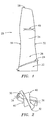
- FIG. 1 shows a fan blade 20 from a gas turbine engine.
- the blade has an inboard blade root 22 configured for attaching the blade to a disk (not shown).
- a platform 24 separates the blade root from an airfoil 26 extending from the platform to a tip 28.
- the airfoil has a leading edge 30 and a trailing edge 32 with suction and pressure sides 34 and 36 extending therebetween.
- a midspan damper shroud projection 40 extends from each of the pressure and suction side surfaces.
- the pressure and suction side projections 40 may respectively interact with the suction and pressure side projections of the adjacent blades to damp blade oscillation.
- the rotating mass of the midspan shroud projections along with forces from their interaction with adjacent projections subjects the blade to high stresses in areas proximate and inboard of these projections. These stresses may limit repairability of these areas relative to other less-stressed areas.
- EBPVD electron beam physical vapor deposition
- the deposited material may have enhanced strength and enhanced adhesion to the base material relative to welding repair techniques. The deposition advantageously occurs in the absence of a transient liquid phase, with solidification directly from the vapor cloud.
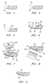
- FIG. 3 shows localized damage such as is associated with foreign object damage (FOD) nicking or chipping the airfoil proximate the leading edge to create a damaged leading portion 30'.
- FIG. 4 shows more general damage such as a leading edge eroded to a location 30". The damage site is advantageously cleaned of contamination Further removal of base material may provide an advantageous base surface for receiving deposition.
- the remaining base material of the blade is ground to a preset configuration such as providing an angled leading facet or base surface 50 (FIG. 5).
- the facet is shown at an included angle ⁇ 1 to the concave pressure side surface 36.
- Exemplary ⁇ 1 are over 120°, more narrowly, 120°-130°.
- the position/orientation of the facet 50 may depend on a number of factors and may be fixed based upon the location of the damage so that, in a given repair facility, any damage at a given point on the airfoil will result in similar machining.
- a backing scaffold/mask element 52 is secured to the airfoil projecting beyond the facet 50 adjacent to the location of the lost/removed material.
- the backing element 52 may be a metallic (e.g., aluminum) tape having first and second surfaces 53 and 54, a trailing portion of the first surface 53 being secured to a remaining intact leading portion of the suction side surface 34.
- a forward portion of the surface 53 protrudes beyond the lost leading edge 30 and an intermediate portion extends aligned with a lost portion of the surface 34 along the original contour of the airfoil.
- the surface 53 may extend fully or partially to either side of alignment with the lost original surface contour.
- the blade may then be positioned relative to a vapor source 58 emitting vapors along line of sight paths 502.
- the source/paths are oriented so that the paths are within slight angles ⁇ 2 and ⁇ 3 off perpendicular to the surfaces 50 and 36. Exemplary ⁇ 2 and ⁇ 3 are less than 30°.
- Deposition from the source 58 builds up a first repair material 60. This is advantageously built up to a surface contour 62 beyond the pressure side portion of the lost original contour of the airfoil. Curvature of the surface 36 produces associated change in ⁇ 3 along the deposition-receiving portion of such surface adjacent the base surface 50.
- the blade may be further machined to remove the backing element 52 and create a second facet or base surface 64 extending along the deposited material 60 and the original base material.
- this machining process further removes a previously intact leading portion of the suction side surface 34.
- the blade may be reoriented relative to the source 58 so that the surfaces 64 and 34 are just slightly off perpendicular to the paths 502 and a second additional material 66 deposited thereatop to reach a contour 68 beyond the suction side portion of the lost original contour.
- the deposited materials 60 and 66 may then be machined down to a specified final contour advantageously identical to the lost original contour (FIG. 9). Thereafter, additional surface treatments and/or protective coatings may be applied.
- the exemplary restoration material is Ti-6Al-4V deposited by an EBPVD or an ion-enhanced EBPVD process.
- the EBPVD process is believed to provide advantageous physical properties via deposition in the absence of a transient liquid phase. EBPVD is believed to have lower residual stress and better adhesion than other processes such as plasma spray deposition.
- the exemplary deposition is performed in a vacuum chamber at a pressure between 10 -3 and 10 -6 torr, more narrowly, approximately 10 -4 torr.
- the exemplary deposition rates are between 10 and 50 micrometers per minute, more narrowly, approximately 20 micrometers per minute.
- the localized deposition may build up to essentially any depth in one or more stages, the separate stages being characterized by some combination of intervening machining or repositioning of the component relative to the ion source. Individual stages may well deposit material to depths over 2 mm, over 5 mm, or even more. For particularly expensive components, the process could be utilized to completely replace lost features. For example, if a blade is broken off of a unitary disk and blade ring, a replacement blade may be built up from the disk.
- the same procedure may be used to restore material to the trailing edge of the airfoil or to the leading or trailing edges of the midspan shroud or to tip regions, even where lost material has exceeded traditional repair limits. Similar deposition could effect repairs on the suction or pressure side surfaces more remote from the edges. For such repairs, single deposition stages would typically be sufficient. On a convex surface (e.g., of the suction side), a relatively flat facet machining could be particularly convenient. On a concave surface (e.g., of the pressure side) a concave machining (e.g., with a doubly convex grinding quill) may be appropriate. Advantageously, with such concave machining the machined surface remains within the desired angle of normal to the vapor paths along its entire area.
- Machining other than the flat-facet grinding may be utilized.
- the most important element of effective machining is providing a clean base surface for subsequent deposition.
- a desired or acceptable level of roughness may be provided.
- the blade remains stationary during each deposition stage so as to limit the presence of columnar discontinuities in the deposited material.
- Applicant's co-pending European Patent Application No. 04251195.6 discloses a method of restoring a fan blade dovetail using a deposition technique.
- the Applicant expressly reserves the right in this application to disclaim any subject matter disclosed in the said co-pending application.
Abstract
Description
- The invention relates to the restoration of turbine elements. More particularly, the invention relates to the restoration of worn or damaged gas turbine engine fan blades and compressor blades and vanes.
- The components of gas turbine engines are subject to wear and damage. Even moderate wear and damage of certain components may interfere with proper operation of the engine. Particular areas of concern involve the airfoils of various blades and vanes. Wear and damage may interfere with their aerodynamic efficiency, produce dynamic force imbalances, and even structurally compromise the worn/damaged parts in more extreme cases. A limited reconditioning is commonly practiced for slightly worn or damaged airfoils wherein additional material is removed yet further below the wear/damage to provide the airfoil with a relatively efficient and clean sectional profile albeit smaller than the original or prior profile. Exemplary inspection criteria establishing the limits to which such reconditioning can be made are shown in Pratt & Whitney JT8D Engine Manual (P/N 773128), ATA 72-33-21, Inspection - 01,United Technologies Corp., East Hartford Connecticut. Such limits may differ among airfoils depending upon the location and particular application. The limits are based on structural and performance considerations which limit the amount of material that may be removed.
- Various techniques have been proposed for more extensive restoration of worn or damaged components of gas turbine engines. U.S. Patent No. 4,822,248 discloses use of a plasma torch to deposit nickel- or cobalt-based superalloy material. U. S. Patent No. 5,732,467 identifies the use of high velocity oxy-fuel (HVOF) and low pressure plasma spray (LPPS) techniques for repairing cracks in such turbine elements. U.S. Patent No. 5,783,318 also identifies LPPS techniques in addition to laser welding and plasma transferred arc welding. U.S. Patent No. 6,049,978 identifies further use of HVOF techniques. Such techniques have offered a limited ability to build up replacement material to restore an original or near original cross-section. However, the structural properties of the replacement material may be substantially limited relative to those of the base material.
- Especially for larger damage, it is known to use preformed inserts which may be welded in place to repair damage. With such inserts, the damaged area is cut away to the predetermined shape of the insert which is, in turn, welded in place. Structural limits associated with the welding limit the capability of such repair techniques to relatively low stress regions of the airfoil as with other techniques. It is common for engine repair manuals to specify the low stress areas where weld repair is permissible. Thus substantial combinations of the extent of the wear/damage and the stress to which the worn/damaged area is subject may limit use of such techniques. High stress areas often include areas near (especially inboard of) a midspan shroud of a fan blade.
- Accordingly, one aspect of the invention involves a method for restoring a Ti alloy component which has lost first material from a damage site. Additional material may be removed at least partially from the damage site to create a base surface. A Ti-based material is physically deposited atop the base surface at least partially in place of the first material and the additional material.
- In various implementations, the Ti-based material may be Ti-6Al-4V, Ti-6Al-2Sn-4Zr-2Mo or Ti-8A1-1V-1Mo and may be essentially identical to the base Ti alloy of the component. The removing of additional material may be, in major part, from undamaged portions of the component. The deposited material may, in major part, essentially, or totally replace the first and additional material. The component may be a blade having a root and an airfoil and the damage site may be along a leading edge of the airfoil inboard of a midspan shroud of the airfoil. The damage site may be inboard of the midspan shroud by an exemplary no more than 15% of a span of the airfoil. The damage site may be located between 30% of such span inboard of the midspan shroud and 20% of such span outboard of the midspan shroud. Such inboard and outboard limits may, more narrowly, be 20% and 10%. The first material may be lost to a depth of at least 2.0 mm. The method may further involve applying a backing element to the component protruding adjacent the damage site after the removal so that the deposited metal builds up on the base surface and backing element. The method may further involve at least partially removing the backing element and machining adjacent deposited material and preexisting material of the component to create a second base surface. More of the metal may then be physically deposited atop the second base surface. The depositing may include vapor deposition, electron beam physical vapor deposition, and electron beam flash vapor deposition.
- The details of one or more embodiments of the invention are set forth in the accompanying drawings and the description below. Other features and advantages of the invention will be apparent from the description and drawings, and from the claims.
-
- FIG. 1 is a view of an airfoil of a fan of a gas turbine engine.
- FIG. 2 is a tip-inward view of the airfoil of FIG. 1.
- FIG. 3 is a partial sectional view of the airfoil of FIG. 1 upon damage.
- FIG. 4 is a partial sectional view of the airfoil of FIG. 1 upon wear.
- FIG. 5 is a partial sectional view of the airfoil of FIG. 1 after machining to remove damaged/worn surfaces.
- FIG. 6 is a partial sectional view of the airfoil of FIG. 5 after the application of a backing element.
- FIG. 7 is a partial sectional view of the airfoil of FIG. 6 after deposition of initial material to rebuild the airfoil.
- FIG. 8 is a partial sectional view of the airfoil of FIG. 7 after further machining and deposition of additional material to rebuild the airfoil
- FIG. 9 is a view of the airfoil of FIG. 8 after further machining.
-
- Like reference numbers and designations in the various drawings indicate like elements.
- FIG. 1 shows a
fan blade 20 from a gas turbine engine. The blade has aninboard blade root 22 configured for attaching the blade to a disk (not shown). Aplatform 24 separates the blade root from anairfoil 26 extending from the platform to atip 28. The airfoil has a leadingedge 30 and atrailing edge 32 with suction andpressure sides damper shroud projection 40 extends from each of the pressure and suction side surfaces. - The pressure and
suction side projections 40 may respectively interact with the suction and pressure side projections of the adjacent blades to damp blade oscillation. The rotating mass of the midspan shroud projections along with forces from their interaction with adjacent projections subjects the blade to high stresses in areas proximate and inboard of these projections. These stresses may limit repairability of these areas relative to other less-stressed areas. It has been discovered that electron beam physical vapor deposition (EBPVD) may be used to deposit repair material with low residual stress and with properties substantially the same as the underlying base material. The deposited material may have enhanced strength and enhanced adhesion to the base material relative to welding repair techniques. The deposition advantageously occurs in the absence of a transient liquid phase, with solidification directly from the vapor cloud. - FIG. 3 shows localized damage such as is associated with foreign object damage (FOD) nicking or chipping the airfoil proximate the leading edge to create a damaged leading portion 30'. FIG. 4 shows more general damage such as a leading edge eroded to a
location 30". The damage site is advantageously cleaned of contamination Further removal of base material may provide an advantageous base surface for receiving deposition. In the exemplary restoration procedure, after the damage/wear, the remaining base material of the blade is ground to a preset configuration such as providing an angled leading facet or base surface 50 (FIG. 5). The facet is shown at an included angle 1 to the concavepressure side surface 36. Exemplary 1 are over 120°, more narrowly, 120°-130°. The position/orientation of thefacet 50 may depend on a number of factors and may be fixed based upon the location of the damage so that, in a given repair facility, any damage at a given point on the airfoil will result in similar machining. - In an optional illustrated variation, a backing scaffold/
mask element 52 is secured to the airfoil projecting beyond thefacet 50 adjacent to the location of the lost/removed material. In the exemplary embodiment, thebacking element 52 may be a metallic (e.g., aluminum) tape having first andsecond surfaces first surface 53 being secured to a remaining intact leading portion of thesuction side surface 34. A forward portion of thesurface 53 protrudes beyond the lost leadingedge 30 and an intermediate portion extends aligned with a lost portion of thesurface 34 along the original contour of the airfoil. In optional variations, thesurface 53 may extend fully or partially to either side of alignment with the lost original surface contour. - The blade may then be positioned relative to a
vapor source 58 emitting vapors along line ofsight paths 502. Advantageously the source/paths are oriented so that the paths are within slight angles 2 and 3 off perpendicular to thesurfaces source 58 builds up afirst repair material 60. This is advantageously built up to asurface contour 62 beyond the pressure side portion of the lost original contour of the airfoil. Curvature of thesurface 36 produces associated change in 3 along the deposition-receiving portion of such surface adjacent thebase surface 50. - After this deposition stage, the blade may be further machined to remove the
backing element 52 and create a second facet orbase surface 64 extending along the depositedmaterial 60 and the original base material. In the exemplary embodiment, this machining process further removes a previously intact leading portion of thesuction side surface 34. The blade may be reoriented relative to thesource 58 so that thesurfaces paths 502 and a secondadditional material 66 deposited thereatop to reach acontour 68 beyond the suction side portion of the lost original contour. The depositedmaterials - The exemplary restoration material is Ti-6Al-4V deposited by an EBPVD or an ion-enhanced EBPVD process. The EBPVD process is believed to provide advantageous physical properties via deposition in the absence of a transient liquid phase. EBPVD is believed to have lower residual stress and better adhesion than other processes such as plasma spray deposition. The exemplary deposition is performed in a vacuum chamber at a pressure between 10-3 and 10-6 torr, more narrowly, approximately 10-4 torr. The exemplary deposition rates are between 10 and 50 micrometers per minute, more narrowly, approximately 20 micrometers per minute. The localized deposition may build up to essentially any depth in one or more stages, the separate stages being characterized by some combination of intervening machining or repositioning of the component relative to the ion source. Individual stages may well deposit material to depths over 2 mm, over 5 mm, or even more. For particularly expensive components, the process could be utilized to completely replace lost features. For example, if a blade is broken off of a unitary disk and blade ring, a replacement blade may be built up from the disk.
- The same procedure may be used to restore material to the trailing edge of the airfoil or to the leading or trailing edges of the midspan shroud or to tip regions, even where lost material has exceeded traditional repair limits. Similar deposition could effect repairs on the suction or pressure side surfaces more remote from the edges. For such repairs, single deposition stages would typically be sufficient. On a convex surface (e.g., of the suction side), a relatively flat facet machining could be particularly convenient. On a concave surface (e.g., of the pressure side) a concave machining (e.g., with a doubly convex grinding quill) may be appropriate. Advantageously, with such concave machining the machined surface remains within the desired angle of normal to the vapor paths along its entire area.
- Machining other than the flat-facet grinding may be utilized. The most important element of effective machining is providing a clean base surface for subsequent deposition. Although advantageously smooth, a desired or acceptable level of roughness may be provided. Advantageously, the blade remains stationary during each deposition stage so as to limit the presence of columnar discontinuities in the deposited material.
- One or more embodiments of the present invention have been described. Nevertheless, it will be understood that various modifications may be made without departing from the scope of the invention. For example, although particularly useful with blades having midspan shrouds, the methods may be applied to other blades and other turbine components and non-turbine components. Details of the particular turbine engine component or other piece and the particular wear or damage suffered may influence details of any given restoration. For example, the method maybe applied to any part of a blade airfoil. Accordingly, other embodiments are within the scope of the following claims.
- Applicant's co-pending European Patent Application No. 04251195.6 discloses a method of restoring a fan blade dovetail using a deposition technique. The Applicant expressly reserves the right in this application to disclaim any subject matter disclosed in the said co-pending application.
Claims (17)
- A method for restoring a Ti alloy turbine component (20) which has lost first material from a damage site comprising:physically depositing a Ti-based material at least partially in place of the first material
- The method of claim 1 wherein:the method further comprises removing additional material at least partially from the damage site to create a base surface (50) ; andthe physically depositing deposits said Ti-based material atop the base surface (50) at least partially in place of the first material and the additional material.
- The method of claim 2 wherein the removing of additional material is, in major part, from undamaged portions of the component.
- The method of claim 1, 2 or 3 wherein:said deposited Ti-based material in major part replaces said first material.
- The method of any preceding claim wherein said Ti-based material is selected from the group consisting of Ti-6Al-4V, Ti-6Al-2Sn-4Zr-2Mo, and Ti-8A1-1V-1Mo.
- The method of any preceding claim wherein the component (20) is a blade having a root (22) and an airfoil (26) and the damage site is along a leading edge (30) of the airfoil inboard of a midspan shroud (40) of the airfoil.
- The method of claim 6 wherein the damage site is inboard of the midspan shroud (40) by no more than 15% of a span of the airfoil (26).
- The method of any of claims 1 to 5 wherein the component is a blade (20) having a root (22) and an airfoil (26) and the damage site is along a leading edge (30) of the airfoil between 20% of an airfoil span inboard of a midspan shroud (40) of the airfoil and 10% of said span outboard of said midspan shroud (40).
- The method of any of claims 1 to 5 wherein the component is a blade (20) having a root (22) and an airfoil (26) and the damage site is along a leading edge (30) of the airfoil between 30% of said span inboard of a midspan shroud (40) of the airfoil and 20% of said span outboard of said midspan shroud (40).
- The method of any preceding claim wherein the first material is lost to a depth of at least 2.0 mm.
- The method of any preceding claim further comprising:applying a backing element (52) to the component (20) protruding adjacent the damage site after said removal so that the deposited Ti-based material builds up on the base surface and backing element (52) .
- The method of claim 11 further comprising:at least partially removing the backing element (52) and machining adjacent deposited material and preexisting material of the component to create a second base surface (64) ; andphysically depositing more of the Ti-based material atop the second base surface (64).
- The method of any preceding claim wherein:wherein said physically depositing said Ti-based material comprises performing physical deposition in a manner selected from the group consisting of vapor deposition, electron beam physical vapor deposition, and electron beam flash vapor deposition.
- The method of claim 13 wherein said physically depositing is performed at a pressure between 10-3 and 10-6 torr.
- The method of claim 14 wherein said performing said physical deposition is performed at a pressure of approximately 10-4 torr.
- The method of claim 13, 14 or 15 wherein said physically depositing said metal is performed at a rate between 10 and 50 micrometers per minute.
- The method of claim 16 wherein said physically depositing said Ti-based material is performed at a rate of approximately 20 micrometers per minute.
Applications Claiming Priority (2)
| Application Number | Priority Date | Filing Date | Title |
|---|---|---|---|
| US10/635,694 US7216428B2 (en) | 2003-03-03 | 2003-08-05 | Method for turbine element repairing |
| US635694 | 2003-08-05 |
Publications (3)
| Publication Number | Publication Date |
|---|---|
| EP1505168A2 true EP1505168A2 (en) | 2005-02-09 |
| EP1505168A3 EP1505168A3 (en) | 2006-06-14 |
| EP1505168B1 EP1505168B1 (en) | 2008-10-08 |
Family
ID=33552946
Family Applications (1)
| Application Number | Title | Priority Date | Filing Date |
|---|---|---|---|
| EP04254725A Not-in-force EP1505168B1 (en) | 2003-08-05 | 2004-08-05 | Turbine element repair |
Country Status (9)
| Country | Link |
|---|---|
| US (1) | US7216428B2 (en) |
| EP (1) | EP1505168B1 (en) |
| JP (1) | JP4021883B2 (en) |
| KR (1) | KR100704805B1 (en) |
| CN (1) | CN1584103A (en) |
| AT (1) | ATE410530T1 (en) |
| DE (1) | DE602004016922D1 (en) |
| SG (1) | SG109003A1 (en) |
| UA (2) | UA79258C2 (en) |
Cited By (2)
| Publication number | Priority date | Publication date | Assignee | Title |
|---|---|---|---|---|
| EP1584702A1 (en) * | 2004-04-06 | 2005-10-12 | United Technologies Corporation | Deposition repair of hollow items |
| CN113088962A (en) * | 2021-04-02 | 2021-07-09 | 中国人民解放军空军工程大学 | Laser cladding multi-azimuth repairing method for titanium alloy thin-wall blade damaged part |
Families Citing this family (43)
| Publication number | Priority date | Publication date | Assignee | Title |
|---|---|---|---|---|
| US7509734B2 (en) * | 2003-03-03 | 2009-03-31 | United Technologies Corporation | Repairing turbine element |
| US7216428B2 (en) | 2003-03-03 | 2007-05-15 | United Technologies Corporation | Method for turbine element repairing |
| US7264538B2 (en) * | 2005-08-12 | 2007-09-04 | United Technologies Corporation | Method of removing a coating |
| CN100398699C (en) * | 2005-08-17 | 2008-07-02 | 大连理工大学 | Cleaning and servicing technology for turbine blade basal body surface by strong current pulsed ionizing beam |
| US20070079507A1 (en) * | 2005-10-12 | 2007-04-12 | Kenny Cheng | Blade shroud repair |
| SG134184A1 (en) * | 2006-01-16 | 2007-08-29 | United Technologies Corp | Chordwidth restoration of a trailing edge of a turbine airfoil by laser clad |
| US20080236536A1 (en) * | 2007-03-30 | 2008-10-02 | Caterpillar Inc. | Cast engine component having metallurgically bonded inserts |
| US20090068349A1 (en) * | 2007-09-12 | 2009-03-12 | Mccall Thomas | Method of repairing a turbine engine component |
| US8020295B2 (en) * | 2007-10-18 | 2011-09-20 | United Technologies Corp. | Methods for dimensionally restoring a fastener for a gas turbine engine |
| US8778487B2 (en) * | 2008-10-16 | 2014-07-15 | Rolls-Royce Corporation | Tape |
| US20100098896A1 (en) * | 2008-10-16 | 2010-04-22 | Edward Claude Rice | Patch |
| US8202056B2 (en) * | 2008-10-16 | 2012-06-19 | Rolls-Royce Corporation | Morphable composite structure |
| US9085053B2 (en) * | 2009-12-22 | 2015-07-21 | United Technologies Corporation | In-situ turbine blade tip repair |
| US9175568B2 (en) | 2010-06-22 | 2015-11-03 | Honeywell International Inc. | Methods for manufacturing turbine components |
| US8673397B2 (en) | 2010-11-10 | 2014-03-18 | General Electric Company | Methods of fabricating and coating a component |
| US9249491B2 (en) | 2010-11-10 | 2016-02-02 | General Electric Company | Components with re-entrant shaped cooling channels and methods of manufacture |
| US8753071B2 (en) | 2010-12-22 | 2014-06-17 | General Electric Company | Cooling channel systems for high-temperature components covered by coatings, and related processes |
| US9085980B2 (en) | 2011-03-04 | 2015-07-21 | Honeywell International Inc. | Methods for repairing turbine components |
| US8601691B2 (en) | 2011-04-27 | 2013-12-10 | General Electric Company | Component and methods of fabricating a coated component using multiple types of fillers |
| US8506836B2 (en) | 2011-09-16 | 2013-08-13 | Honeywell International Inc. | Methods for manufacturing components from articles formed by additive-manufacturing processes |
| US9249672B2 (en) | 2011-09-23 | 2016-02-02 | General Electric Company | Components with cooling channels and methods of manufacture |
| US20130086784A1 (en) | 2011-10-06 | 2013-04-11 | General Electric Company | Repair methods for cooled components |
| US9249670B2 (en) | 2011-12-15 | 2016-02-02 | General Electric Company | Components with microchannel cooling |
| US9266170B2 (en) | 2012-01-27 | 2016-02-23 | Honeywell International Inc. | Multi-material turbine components |
| US9435208B2 (en) | 2012-04-17 | 2016-09-06 | General Electric Company | Components with microchannel cooling |
| US9243503B2 (en) | 2012-05-23 | 2016-01-26 | General Electric Company | Components with microchannel cooled platforms and fillets and methods of manufacture |
| US9120151B2 (en) | 2012-08-01 | 2015-09-01 | Honeywell International Inc. | Methods for manufacturing titanium aluminide components from articles formed by consolidation processes |
| DE102013109116A1 (en) | 2012-08-27 | 2014-03-27 | General Electric Company (N.D.Ges.D. Staates New York) | Component with cooling channels and method of manufacture |
| US8974859B2 (en) | 2012-09-26 | 2015-03-10 | General Electric Company | Micro-channel coating deposition system and method for using the same |
| US9238265B2 (en) | 2012-09-27 | 2016-01-19 | General Electric Company | Backstrike protection during machining of cooling features |
| US9242294B2 (en) | 2012-09-27 | 2016-01-26 | General Electric Company | Methods of forming cooling channels using backstrike protection |
| US9200521B2 (en) | 2012-10-30 | 2015-12-01 | General Electric Company | Components with micro cooled coating layer and methods of manufacture |
| US9562436B2 (en) | 2012-10-30 | 2017-02-07 | General Electric Company | Components with micro cooled patterned coating layer and methods of manufacture |
| US9003657B2 (en) | 2012-12-18 | 2015-04-14 | General Electric Company | Components with porous metal cooling and methods of manufacture |
| CN103498813B (en) * | 2013-05-23 | 2016-08-10 | 哈尔滨汽轮机厂有限责任公司 | A kind of low pressure chopped-off head moving vane of 20-30MW grade gas turbine compressor |
| US9278462B2 (en) | 2013-11-20 | 2016-03-08 | General Electric Company | Backstrike protection during machining of cooling features |
| US9476306B2 (en) | 2013-11-26 | 2016-10-25 | General Electric Company | Components with multi-layered cooling features and methods of manufacture |
| CN103831574B (en) * | 2013-12-10 | 2016-03-23 | 贵州黎阳航空动力有限公司 | Hollow turbine vane blade blanking cover renovation technique |
| ITCO20130067A1 (en) * | 2013-12-17 | 2015-06-18 | Nuovo Pignone Srl | IMPELLER WITH PROTECTION ELEMENTS AND CENTRIFUGAL COMPRESSOR |
| US10927684B2 (en) | 2016-02-08 | 2021-02-23 | Raytheon Technologies Corporation | Repairing a coating with a pre-configured coating patch |
| EP3417989B1 (en) * | 2017-06-21 | 2023-12-27 | General Electric Technology GmbH | Method of repairing a turbomachine component |
| CN109483146B (en) * | 2018-10-15 | 2020-06-09 | 中国航发北京航空材料研究院 | Method for repairing defects of titanium-aluminum intermetallic compound casting |
| KR102123192B1 (en) * | 2019-12-30 | 2020-06-15 | 한전케이피에스 주식회사 | Method for life extension of erosion damaged steam turbine Last Stage Blade |
Citations (5)
| Publication number | Priority date | Publication date | Assignee | Title |
|---|---|---|---|---|
| EP1138431A2 (en) * | 2000-03-27 | 2001-10-04 | United Technologies Corporation | Method of repairing an airfoil |
| EP1217090A1 (en) * | 2000-12-19 | 2002-06-26 | United Technologies Corporation | Vapor deposition repair of superalloy articles |
| US20020195176A1 (en) * | 2001-04-17 | 2002-12-26 | Smith Michael P. | Integrally bladed rotor airfoil fabrication and repair techniques |
| WO2003028428A2 (en) * | 2001-09-10 | 2003-04-10 | University Of Virginia Patent Foundation | Method and apparatus application of metallic alloy coatings |
| EP1454707A1 (en) * | 2003-03-03 | 2004-09-08 | United Technologies Corporation | Fan and compressor blade dovetail restoration process |
Family Cites Families (19)
| Publication number | Priority date | Publication date | Assignee | Title |
|---|---|---|---|---|
| US763229A (en) | 1903-07-23 | 1904-06-21 | Charles P Watson | Shell-fuse. |
| US3574924A (en) * | 1968-10-28 | 1971-04-13 | North American Rockwell | Solid state repair method and means |
| US4822248A (en) | 1987-04-15 | 1989-04-18 | Metallurgical Industries, Inc. | Rebuilt shrouded turbine blade and method of rebuilding the same |
| US5038014A (en) * | 1989-02-08 | 1991-08-06 | General Electric Company | Fabrication of components by layered deposition |
| US5111570A (en) * | 1990-08-10 | 1992-05-12 | United Technologies Corporation | Forge joining repair technique |
| US5451142A (en) | 1994-03-29 | 1995-09-19 | United Technologies Corporation | Turbine engine blade having a zone of fine grains of a high strength composition at the blade root surface |
| DE4412906C1 (en) | 1994-04-14 | 1995-07-13 | Fraunhofer Ges Forschung | Ion-assisted vacuum coating |
| US5783318A (en) | 1994-06-22 | 1998-07-21 | United Technologies Corporation | Repaired nickel based superalloy |
| US5525429A (en) | 1995-03-06 | 1996-06-11 | General Electric Company | Laser shock peening surface enhancement for gas turbine engine high strength rotor alloy repair |
| WO1997037052A1 (en) | 1996-04-03 | 1997-10-09 | Zakrytoe Aktsionernoe Obschestvo 'skb 'istra' | Method and device for applying porous coatings and cathode film of an electrolytic condenser |
| US5732467A (en) | 1996-11-14 | 1998-03-31 | General Electric Company | Method of repairing directionally solidified and single crystal alloy parts |
| US6049978A (en) | 1996-12-23 | 2000-04-18 | Recast Airfoil Group | Methods for repairing and reclassifying gas turbine engine airfoil parts |
| US6302625B1 (en) | 1999-10-15 | 2001-10-16 | United Technologies Corporation | Method and apparatus for refurbishing a gas turbine airfoil |
| WO2001065590A2 (en) | 2000-03-02 | 2001-09-07 | Tokyo Electron Limited | Esrf source for ion plating epitaxial deposition |
| US6605160B2 (en) | 2000-08-21 | 2003-08-12 | Robert Frank Hoskin | Repair of coatings and surfaces using reactive metals coating processes |
| US6427327B1 (en) * | 2000-11-29 | 2002-08-06 | General Electric Company | Method of modifying cooled turbine components |
| JP2003188115A (en) | 2001-12-17 | 2003-07-04 | Shin Meiwa Ind Co Ltd | Method and apparatus for semiconductor wiring formation, method and apparatus for manufacturing semiconductor device, and wafer |
| US6754955B1 (en) * | 2003-01-30 | 2004-06-29 | General Electric Company | Method or repairing trailing edge portions of partitions in turbine diaphragms |
| US7216428B2 (en) | 2003-03-03 | 2007-05-15 | United Technologies Corporation | Method for turbine element repairing |
-
2003
- 2003-08-05 US US10/635,694 patent/US7216428B2/en not_active Expired - Lifetime
-
2004
- 2004-07-12 UA UA20040705668A patent/UA79258C2/en unknown
- 2004-07-12 UA UA20040705667A patent/UA81401C2/en unknown
- 2004-07-14 KR KR1020040054708A patent/KR100704805B1/en not_active IP Right Cessation
- 2004-07-22 SG SG200404374A patent/SG109003A1/en unknown
- 2004-08-05 AT AT04254725T patent/ATE410530T1/en not_active IP Right Cessation
- 2004-08-05 DE DE602004016922T patent/DE602004016922D1/en active Active
- 2004-08-05 EP EP04254725A patent/EP1505168B1/en not_active Not-in-force
- 2004-08-05 JP JP2004229402A patent/JP4021883B2/en active Active
- 2004-08-05 CN CNA2004100560279A patent/CN1584103A/en active Pending
Patent Citations (5)
| Publication number | Priority date | Publication date | Assignee | Title |
|---|---|---|---|---|
| EP1138431A2 (en) * | 2000-03-27 | 2001-10-04 | United Technologies Corporation | Method of repairing an airfoil |
| EP1217090A1 (en) * | 2000-12-19 | 2002-06-26 | United Technologies Corporation | Vapor deposition repair of superalloy articles |
| US20020195176A1 (en) * | 2001-04-17 | 2002-12-26 | Smith Michael P. | Integrally bladed rotor airfoil fabrication and repair techniques |
| WO2003028428A2 (en) * | 2001-09-10 | 2003-04-10 | University Of Virginia Patent Foundation | Method and apparatus application of metallic alloy coatings |
| EP1454707A1 (en) * | 2003-03-03 | 2004-09-08 | United Technologies Corporation | Fan and compressor blade dovetail restoration process |
Cited By (2)
| Publication number | Priority date | Publication date | Assignee | Title |
|---|---|---|---|---|
| EP1584702A1 (en) * | 2004-04-06 | 2005-10-12 | United Technologies Corporation | Deposition repair of hollow items |
| CN113088962A (en) * | 2021-04-02 | 2021-07-09 | 中国人民解放军空军工程大学 | Laser cladding multi-azimuth repairing method for titanium alloy thin-wall blade damaged part |
Also Published As
| Publication number | Publication date |
|---|---|
| JP2005054801A (en) | 2005-03-03 |
| ATE410530T1 (en) | 2008-10-15 |
| KR20050016002A (en) | 2005-02-21 |
| CN1584103A (en) | 2005-02-23 |
| JP4021883B2 (en) | 2007-12-12 |
| UA79258C2 (en) | 2007-06-11 |
| KR100704805B1 (en) | 2007-04-10 |
| EP1505168A3 (en) | 2006-06-14 |
| DE602004016922D1 (en) | 2008-11-20 |
| SG109003A1 (en) | 2005-02-28 |
| US20040172825A1 (en) | 2004-09-09 |
| US7216428B2 (en) | 2007-05-15 |
| UA81401C2 (en) | 2008-01-10 |
| EP1505168B1 (en) | 2008-10-08 |
Similar Documents
| Publication | Publication Date | Title |
|---|---|---|
| EP1505168B1 (en) | Turbine element repair | |
| EP1584702B1 (en) | Deposition repair of hollow items | |
| EP1685923B1 (en) | Repair and reclassification of superalloy components | |
| US7896728B2 (en) | Machining methods using superabrasive tool | |
| US6049978A (en) | Methods for repairing and reclassifying gas turbine engine airfoil parts | |
| US5956845A (en) | Method of repairing a turbine engine airfoil part | |
| EP2995410A1 (en) | Method of blade tip repair | |
| EP1563945A2 (en) | Repair of article by laser cladding | |
| US20030088980A1 (en) | Method for correcting defects in a workpiece | |
| US9488053B2 (en) | Method for repairing a single crystal turbine blade | |
| US20020076573A1 (en) | Vapor deposition repair of superalloy articles | |
| US7043819B1 (en) | Methods for forming metal parts having superior surface characteristics | |
| US20030082297A1 (en) | Combustion turbine blade tip restoration by metal build-up using thermal spray techniques | |
| EP1793962A2 (en) | Method to restore an airfoil leading edge | |
| EP1905953A2 (en) | Low plasticity burnishing of coated titanium parts | |
| EP2971531B1 (en) | Blades and manufacture methods | |
| JP2008038896A (en) | Gas turbine engine blade, fabricating method of article of metal material, and manufacturing method of covered component | |
| US20040018299A1 (en) | Method of forming a diffusion coating on the surface of a workpiece | |
| US20040031140A1 (en) | Methods for salvaging a cast article | |
| US20050152805A1 (en) | Method for forming a wear-resistant hard-face contact area on a workpiece, such as a gas turbine engine part | |
| EP3372318B1 (en) | Narrow gap processing | |
| US20090232975A1 (en) | Method for repairing turbine vanes | |
| US20210215053A1 (en) | Movable blade |
Legal Events
| Date | Code | Title | Description |
|---|---|---|---|
| PUAI | Public reference made under article 153(3) epc to a published international application that has entered the european phase |
Free format text: ORIGINAL CODE: 0009012 |
|
| AK | Designated contracting states |
Kind code of ref document: A2 Designated state(s): AT BE BG CH CY CZ DE DK EE ES FI FR GB GR HU IE IT LI LU MC NL PL PT RO SE SI SK TR |
|
| AX | Request for extension of the european patent |
Extension state: AL HR LT LV MK |
|
| PUAL | Search report despatched |
Free format text: ORIGINAL CODE: 0009013 |
|
| AK | Designated contracting states |
Kind code of ref document: A3 Designated state(s): AT BE BG CH CY CZ DE DK EE ES FI FR GB GR HU IE IT LI LU MC NL PL PT RO SE SI SK TR |
|
| AX | Request for extension of the european patent |
Extension state: AL HR LT LV MK |
|
| 17P | Request for examination filed |
Effective date: 20061205 |
|
| AKX | Designation fees paid |
Designated state(s): AT BE BG CH CY CZ DE DK EE ES FI FR GB GR HU IE IT LI LU MC NL PL PT RO SE SI SK TR |
|
| 17Q | First examination report despatched |
Effective date: 20070514 |
|
| GRAP | Despatch of communication of intention to grant a patent |
Free format text: ORIGINAL CODE: EPIDOSNIGR1 |
|
| GRAS | Grant fee paid |
Free format text: ORIGINAL CODE: EPIDOSNIGR3 |
|
| GRAA | (expected) grant |
Free format text: ORIGINAL CODE: 0009210 |
|
| AK | Designated contracting states |
Kind code of ref document: B1 Designated state(s): AT BE BG CH CY CZ DE DK EE ES FI FR GB GR HU IE IT LI LU MC NL PL PT RO SE SI SK TR |
|
| REG | Reference to a national code |
Ref country code: GB Ref legal event code: FG4D |
|
| REG | Reference to a national code |
Ref country code: CH Ref legal event code: EP |
|
| REG | Reference to a national code |
Ref country code: IE Ref legal event code: FG4D |
|
| REF | Corresponds to: |
Ref document number: 602004016922 Country of ref document: DE Date of ref document: 20081120 Kind code of ref document: P |
|
| PG25 | Lapsed in a contracting state [announced via postgrant information from national office to epo] |
Ref country code: SI Free format text: LAPSE BECAUSE OF FAILURE TO SUBMIT A TRANSLATION OF THE DESCRIPTION OR TO PAY THE FEE WITHIN THE PRESCRIBED TIME-LIMIT Effective date: 20081008 |
|
| NLV1 | Nl: lapsed or annulled due to failure to fulfill the requirements of art. 29p and 29m of the patents act | ||
| PG25 | Lapsed in a contracting state [announced via postgrant information from national office to epo] |
Ref country code: ES Free format text: LAPSE BECAUSE OF FAILURE TO SUBMIT A TRANSLATION OF THE DESCRIPTION OR TO PAY THE FEE WITHIN THE PRESCRIBED TIME-LIMIT Effective date: 20090119 Ref country code: AT Free format text: LAPSE BECAUSE OF FAILURE TO SUBMIT A TRANSLATION OF THE DESCRIPTION OR TO PAY THE FEE WITHIN THE PRESCRIBED TIME-LIMIT Effective date: 20081008 Ref country code: BG Free format text: LAPSE BECAUSE OF FAILURE TO SUBMIT A TRANSLATION OF THE DESCRIPTION OR TO PAY THE FEE WITHIN THE PRESCRIBED TIME-LIMIT Effective date: 20090108 |
|
| PG25 | Lapsed in a contracting state [announced via postgrant information from national office to epo] |
Ref country code: PL Free format text: LAPSE BECAUSE OF FAILURE TO SUBMIT A TRANSLATION OF THE DESCRIPTION OR TO PAY THE FEE WITHIN THE PRESCRIBED TIME-LIMIT Effective date: 20081008 Ref country code: FI Free format text: LAPSE BECAUSE OF FAILURE TO SUBMIT A TRANSLATION OF THE DESCRIPTION OR TO PAY THE FEE WITHIN THE PRESCRIBED TIME-LIMIT Effective date: 20081008 Ref country code: NL Free format text: LAPSE BECAUSE OF FAILURE TO SUBMIT A TRANSLATION OF THE DESCRIPTION OR TO PAY THE FEE WITHIN THE PRESCRIBED TIME-LIMIT Effective date: 20081008 Ref country code: PT Free format text: LAPSE BECAUSE OF FAILURE TO SUBMIT A TRANSLATION OF THE DESCRIPTION OR TO PAY THE FEE WITHIN THE PRESCRIBED TIME-LIMIT Effective date: 20090218 |
|
| PG25 | Lapsed in a contracting state [announced via postgrant information from national office to epo] |
Ref country code: DK Free format text: LAPSE BECAUSE OF FAILURE TO SUBMIT A TRANSLATION OF THE DESCRIPTION OR TO PAY THE FEE WITHIN THE PRESCRIBED TIME-LIMIT Effective date: 20081008 Ref country code: BE Free format text: LAPSE BECAUSE OF FAILURE TO SUBMIT A TRANSLATION OF THE DESCRIPTION OR TO PAY THE FEE WITHIN THE PRESCRIBED TIME-LIMIT Effective date: 20081008 Ref country code: RO Free format text: LAPSE BECAUSE OF FAILURE TO SUBMIT A TRANSLATION OF THE DESCRIPTION OR TO PAY THE FEE WITHIN THE PRESCRIBED TIME-LIMIT Effective date: 20081008 Ref country code: EE Free format text: LAPSE BECAUSE OF FAILURE TO SUBMIT A TRANSLATION OF THE DESCRIPTION OR TO PAY THE FEE WITHIN THE PRESCRIBED TIME-LIMIT Effective date: 20081008 |
|
| PLBE | No opposition filed within time limit |
Free format text: ORIGINAL CODE: 0009261 |
|
| STAA | Information on the status of an ep patent application or granted ep patent |
Free format text: STATUS: NO OPPOSITION FILED WITHIN TIME LIMIT |
|
| PG25 | Lapsed in a contracting state [announced via postgrant information from national office to epo] |
Ref country code: CZ Free format text: LAPSE BECAUSE OF FAILURE TO SUBMIT A TRANSLATION OF THE DESCRIPTION OR TO PAY THE FEE WITHIN THE PRESCRIBED TIME-LIMIT Effective date: 20081008 Ref country code: IT Free format text: LAPSE BECAUSE OF FAILURE TO SUBMIT A TRANSLATION OF THE DESCRIPTION OR TO PAY THE FEE WITHIN THE PRESCRIBED TIME-LIMIT Effective date: 20081008 Ref country code: SE Free format text: LAPSE BECAUSE OF FAILURE TO SUBMIT A TRANSLATION OF THE DESCRIPTION OR TO PAY THE FEE WITHIN THE PRESCRIBED TIME-LIMIT Effective date: 20090108 |
|
| 26N | No opposition filed |
Effective date: 20090709 |
|
| PG25 | Lapsed in a contracting state [announced via postgrant information from national office to epo] |
Ref country code: SK Free format text: LAPSE BECAUSE OF FAILURE TO SUBMIT A TRANSLATION OF THE DESCRIPTION OR TO PAY THE FEE WITHIN THE PRESCRIBED TIME-LIMIT Effective date: 20081008 |
|
| PG25 | Lapsed in a contracting state [announced via postgrant information from national office to epo] |
Ref country code: MC Free format text: LAPSE BECAUSE OF NON-PAYMENT OF DUE FEES Effective date: 20090831 |
|
| REG | Reference to a national code |
Ref country code: CH Ref legal event code: PL |
|
| PG25 | Lapsed in a contracting state [announced via postgrant information from national office to epo] |
Ref country code: LI Free format text: LAPSE BECAUSE OF NON-PAYMENT OF DUE FEES Effective date: 20090831 Ref country code: CH Free format text: LAPSE BECAUSE OF NON-PAYMENT OF DUE FEES Effective date: 20090831 |
|
| REG | Reference to a national code |
Ref country code: FR Ref legal event code: ST Effective date: 20100430 |
|
| PG25 | Lapsed in a contracting state [announced via postgrant information from national office to epo] |
Ref country code: FR Free format text: LAPSE BECAUSE OF NON-PAYMENT OF DUE FEES Effective date: 20090831 Ref country code: IE Free format text: LAPSE BECAUSE OF NON-PAYMENT OF DUE FEES Effective date: 20090805 |
|
| PG25 | Lapsed in a contracting state [announced via postgrant information from national office to epo] |
Ref country code: GR Free format text: LAPSE BECAUSE OF FAILURE TO SUBMIT A TRANSLATION OF THE DESCRIPTION OR TO PAY THE FEE WITHIN THE PRESCRIBED TIME-LIMIT Effective date: 20090109 |
|
| PG25 | Lapsed in a contracting state [announced via postgrant information from national office to epo] |
Ref country code: LU Free format text: LAPSE BECAUSE OF NON-PAYMENT OF DUE FEES Effective date: 20090805 |
|
| PG25 | Lapsed in a contracting state [announced via postgrant information from national office to epo] |
Ref country code: HU Free format text: LAPSE BECAUSE OF FAILURE TO SUBMIT A TRANSLATION OF THE DESCRIPTION OR TO PAY THE FEE WITHIN THE PRESCRIBED TIME-LIMIT Effective date: 20090409 |
|
| PG25 | Lapsed in a contracting state [announced via postgrant information from national office to epo] |
Ref country code: TR Free format text: LAPSE BECAUSE OF FAILURE TO SUBMIT A TRANSLATION OF THE DESCRIPTION OR TO PAY THE FEE WITHIN THE PRESCRIBED TIME-LIMIT Effective date: 20081008 |
|
| PG25 | Lapsed in a contracting state [announced via postgrant information from national office to epo] |
Ref country code: CY Free format text: LAPSE BECAUSE OF FAILURE TO SUBMIT A TRANSLATION OF THE DESCRIPTION OR TO PAY THE FEE WITHIN THE PRESCRIBED TIME-LIMIT Effective date: 20081008 |
|
| PGFP | Annual fee paid to national office [announced via postgrant information from national office to epo] |
Ref country code: GB Payment date: 20130731 Year of fee payment: 10 |
|
| GBPC | Gb: european patent ceased through non-payment of renewal fee |
Effective date: 20140805 |
|
| PG25 | Lapsed in a contracting state [announced via postgrant information from national office to epo] |
Ref country code: GB Free format text: LAPSE BECAUSE OF NON-PAYMENT OF DUE FEES Effective date: 20140805 |
|
| REG | Reference to a national code |
Ref country code: DE Ref legal event code: R082 Ref document number: 602004016922 Country of ref document: DE Representative=s name: SCHMITT-NILSON SCHRAUD WAIBEL WOHLFROM PATENTA, DE |
|
| REG | Reference to a national code |
Ref country code: DE Ref legal event code: R082 Ref document number: 602004016922 Country of ref document: DE Representative=s name: SCHMITT-NILSON SCHRAUD WAIBEL WOHLFROM PATENTA, DE Ref country code: DE Ref legal event code: R081 Ref document number: 602004016922 Country of ref document: DE Owner name: UNITED TECHNOLOGIES CORP. (N.D.GES.D. STAATES , US Free format text: FORMER OWNER: UNITED TECHNOLOGIES CORP., HARTFORD, CONN., US |
|
| PGFP | Annual fee paid to national office [announced via postgrant information from national office to epo] |
Ref country code: DE Payment date: 20180719 Year of fee payment: 15 |
|
| REG | Reference to a national code |
Ref country code: DE Ref legal event code: R119 Ref document number: 602004016922 Country of ref document: DE |
|
| PG25 | Lapsed in a contracting state [announced via postgrant information from national office to epo] |
Ref country code: DE Free format text: LAPSE BECAUSE OF NON-PAYMENT OF DUE FEES Effective date: 20200303 |