EP1505004A1 - Safety cap and container with safety cap - Google Patents
Safety cap and container with safety cap Download PDFInfo
- Publication number
- EP1505004A1 EP1505004A1 EP02770181A EP02770181A EP1505004A1 EP 1505004 A1 EP1505004 A1 EP 1505004A1 EP 02770181 A EP02770181 A EP 02770181A EP 02770181 A EP02770181 A EP 02770181A EP 1505004 A1 EP1505004 A1 EP 1505004A1
- Authority
- EP
- European Patent Office
- Prior art keywords
- operating plate
- projection
- safety cap
- plate
- inward
- Prior art date
- Legal status (The legal status is an assumption and is not a legal conclusion. Google has not performed a legal analysis and makes no representation as to the accuracy of the status listed.)
- Granted
Links
Images





Classifications
-
- B—PERFORMING OPERATIONS; TRANSPORTING
- B65—CONVEYING; PACKING; STORING; HANDLING THIN OR FILAMENTARY MATERIAL
- B65D—CONTAINERS FOR STORAGE OR TRANSPORT OF ARTICLES OR MATERIALS, e.g. BAGS, BARRELS, BOTTLES, BOXES, CANS, CARTONS, CRATES, DRUMS, JARS, TANKS, HOPPERS, FORWARDING CONTAINERS; ACCESSORIES, CLOSURES, OR FITTINGS THEREFOR; PACKAGING ELEMENTS; PACKAGES
- B65D55/00—Accessories for container closures not otherwise provided for
- B65D55/02—Locking devices; Means for discouraging or indicating unauthorised opening or removal of closure
-
- B—PERFORMING OPERATIONS; TRANSPORTING
- B65—CONVEYING; PACKING; STORING; HANDLING THIN OR FILAMENTARY MATERIAL
- B65D—CONTAINERS FOR STORAGE OR TRANSPORT OF ARTICLES OR MATERIALS, e.g. BAGS, BARRELS, BOTTLES, BOXES, CANS, CARTONS, CRATES, DRUMS, JARS, TANKS, HOPPERS, FORWARDING CONTAINERS; ACCESSORIES, CLOSURES, OR FITTINGS THEREFOR; PACKAGING ELEMENTS; PACKAGES
- B65D47/00—Closures with filling and discharging, or with discharging, devices
- B65D47/04—Closures with discharging devices other than pumps
- B65D47/06—Closures with discharging devices other than pumps with pouring spouts or tubes; with discharge nozzles or passages
- B65D47/08—Closures with discharging devices other than pumps with pouring spouts or tubes; with discharge nozzles or passages having articulated or hinged closures
- B65D47/0804—Closures with discharging devices other than pumps with pouring spouts or tubes; with discharge nozzles or passages having articulated or hinged closures integrally formed with the base element provided with the spout or discharge passage
- B65D47/0809—Closures with discharging devices other than pumps with pouring spouts or tubes; with discharge nozzles or passages having articulated or hinged closures integrally formed with the base element provided with the spout or discharge passage and elastically biased towards both the open and the closed positions
- B65D47/0814—Closures with discharging devices other than pumps with pouring spouts or tubes; with discharge nozzles or passages having articulated or hinged closures integrally formed with the base element provided with the spout or discharge passage and elastically biased towards both the open and the closed positions by at least three hinge sections, at least one having a length different from the others
-
- B—PERFORMING OPERATIONS; TRANSPORTING
- B65—CONVEYING; PACKING; STORING; HANDLING THIN OR FILAMENTARY MATERIAL
- B65D—CONTAINERS FOR STORAGE OR TRANSPORT OF ARTICLES OR MATERIALS, e.g. BAGS, BARRELS, BOTTLES, BOXES, CANS, CARTONS, CRATES, DRUMS, JARS, TANKS, HOPPERS, FORWARDING CONTAINERS; ACCESSORIES, CLOSURES, OR FITTINGS THEREFOR; PACKAGING ELEMENTS; PACKAGES
- B65D50/00—Closures with means for discouraging unauthorised opening or removal thereof, with or without indicating means, e.g. child-proof closures
- B65D50/02—Closures with means for discouraging unauthorised opening or removal thereof, with or without indicating means, e.g. child-proof closures openable or removable by the combination of plural actions
- B65D50/04—Closures with means for discouraging unauthorised opening or removal thereof, with or without indicating means, e.g. child-proof closures openable or removable by the combination of plural actions requiring the combination of simultaneous actions, e.g. depressing and turning, lifting and turning, maintaining a part and turning another one
- B65D50/045—Closures with means for discouraging unauthorised opening or removal thereof, with or without indicating means, e.g. child-proof closures openable or removable by the combination of plural actions requiring the combination of simultaneous actions, e.g. depressing and turning, lifting and turning, maintaining a part and turning another one where one action elastically deforms or deflects at least part of the closure, the container or an intermediate element, e.g. a ring
- B65D50/046—Closures with means for discouraging unauthorised opening or removal thereof, with or without indicating means, e.g. child-proof closures openable or removable by the combination of plural actions requiring the combination of simultaneous actions, e.g. depressing and turning, lifting and turning, maintaining a part and turning another one where one action elastically deforms or deflects at least part of the closure, the container or an intermediate element, e.g. a ring and such deformation causes the disengagement of locking means, e.g. the release of a pawl-like element from a tooth or abutment, to allow removal of the closure by simultaneous rotation
-
- C—CHEMISTRY; METALLURGY
- C04—CEMENTS; CONCRETE; ARTIFICIAL STONE; CERAMICS; REFRACTORIES
- C04B—LIME, MAGNESIA; SLAG; CEMENTS; COMPOSITIONS THEREOF, e.g. MORTARS, CONCRETE OR LIKE BUILDING MATERIALS; ARTIFICIAL STONE; CERAMICS; REFRACTORIES; TREATMENT OF NATURAL STONE
- C04B38/00—Porous mortars, concrete, artificial stone or ceramic ware; Preparation thereof
- C04B38/009—Porous or hollow ceramic granular materials, e.g. microballoons
-
- C—CHEMISTRY; METALLURGY
- C04—CEMENTS; CONCRETE; ARTIFICIAL STONE; CERAMICS; REFRACTORIES
- C04B—LIME, MAGNESIA; SLAG; CEMENTS; COMPOSITIONS THEREOF, e.g. MORTARS, CONCRETE OR LIKE BUILDING MATERIALS; ARTIFICIAL STONE; CERAMICS; REFRACTORIES; TREATMENT OF NATURAL STONE
- C04B38/00—Porous mortars, concrete, artificial stone or ceramic ware; Preparation thereof
- C04B38/08—Porous mortars, concrete, artificial stone or ceramic ware; Preparation thereof by adding porous substances
-
- B—PERFORMING OPERATIONS; TRANSPORTING
- B65—CONVEYING; PACKING; STORING; HANDLING THIN OR FILAMENTARY MATERIAL
- B65D—CONTAINERS FOR STORAGE OR TRANSPORT OF ARTICLES OR MATERIALS, e.g. BAGS, BARRELS, BOTTLES, BOXES, CANS, CARTONS, CRATES, DRUMS, JARS, TANKS, HOPPERS, FORWARDING CONTAINERS; ACCESSORIES, CLOSURES, OR FITTINGS THEREFOR; PACKAGING ELEMENTS; PACKAGES
- B65D2251/00—Details relating to container closures
- B65D2251/10—Details of hinged closures
- B65D2251/1016—Means for locking the closure in closed position
- B65D2251/1058—Latching mechanisms
-
- B—PERFORMING OPERATIONS; TRANSPORTING
- B65—CONVEYING; PACKING; STORING; HANDLING THIN OR FILAMENTARY MATERIAL
- B65D—CONTAINERS FOR STORAGE OR TRANSPORT OF ARTICLES OR MATERIALS, e.g. BAGS, BARRELS, BOTTLES, BOXES, CANS, CARTONS, CRATES, DRUMS, JARS, TANKS, HOPPERS, FORWARDING CONTAINERS; ACCESSORIES, CLOSURES, OR FITTINGS THEREFOR; PACKAGING ELEMENTS; PACKAGES
- B65D2251/00—Details relating to container closures
- B65D2251/20—Sealing means
Definitions
- the present invention relates to a safety cap, in particular, a cap with a cover which cannot be opened without performing any predetermined cover opening operation, and a container with the cap.
- a cap comprising a cylindrical main body to be fitted to the outer surface of a top opened neck portion and a cover for covering the upper surface of the main body as a cap for a container for containing therein various kinds of contents in addition to drink.
- a cap has an advantage that anyone can easily open the cap, but to the contrary, an infant or the like mischievously opens the cap, thereby resulting in a possibility that the contents spill around or is unjustly drained out.
- the structures of the safety caps disclosed in the above items (1) to (3) have a restriction of application only to a type screwed to the neck portion of the container.
- a type having the cover connected to the cap main body via the hinge is used as a cap for a squeeze type container containing detergent and the like therein in such a manner as to facilitate an opening/closing operation.
- the safety cap applicable to such a type has been proposed the safety cap disclosed in the above item (4), in which since the lower portion of the operating plate is exposed to the outside as a depressing button in the configuration of the cap, there may occur a disadvantage depending on the use of the cap for the reason of degradation of the outside appearance of the cap or adhesion of dust to the lower portion of the operating plate.
- the locking piece for maintaining a cover closed state is formed as a part of the cover peripheral wall (specifically, the right and left sides).
- the locking piece must be pushed inward of the cap, and at the same time, the cover front portion must be rotated in the opening direction, and therefore, the cover opening operation becomes slightly complicated in comparison with the cap disclosed in the above item (4) in which the cover is released simply by pressing up the lower portion of the operating plate at the time of the inward pressing.
- a first object of the present invention is to provide a container with ease of use for an adult while keeping the function of preventing unexpected or unjust use of a safety cap by an infant or the like.
- a safety cap for disposing a container including:
- the lower end of the operating plate should be formed into the connection portion serving as a fixing end, around which the operating plate can be disposed in a freely inward swingable manner as a whole while.
- the fixing member should be constituted of an engaging piece disposed at the operating plate, and an engaging piece receiver disposed at the cap main body except for the operating plate.
- a second object of the present invention is to provide a convenient safety cap capable of releasing engagement of the engaging means and fixing an operating plate by a single operation of pushing the operating plate inward.
- the engaging piece serves as an upper end of the operating plate, and further, the engaging piece receiver is a projection formed at an undersurface of the top plate outward of the inner circumferential wall.
- a third object of the present invention is to provide a safety cap in which the operating plate is fixed by two operations. Consequently, the operating plate is fixed only when a user intends to fix the operating plate.
- the safety cap in which the engaging piece serves as an upper end of the operating plate, and further, the engaging piece receiver is disposed in an elastically bending plate formed at an end of the top plate near the operating plate in such a manner as to engage with the engaging piece when the elastically bending plate is bent downward.
- a fourth object of the present invention is to fix the operating plate to the cap main body by an easy operation, and further, to achieve good appearance in the fixed state.
- the engaging piece serves as a tenon protruding inward from the upper end of the operating plate and being wider at its intermediate portion than a base end and tip end thereof, and further, the engaging piece receiver serves as a tenon groove having a shape in conformity with the tenon, cut out at an end of the top plate near the operating plate.
- a fifth object of the present invention is to conceal the fixing means from a user by fixing the operating plate inside of the cap main body, and further, to facilitate operations for fixing and detaching the operating plate to and from the cap main body.
- the safety cap in which the fixing member is formed of an engaging projection, which is longitudinally disposed at either one of an inner surface of the operating plate and an opposite outer surface of the inner circumferential wall, and an engaging groove, which is disposed at the other and can engage with the engaging projection.
- a sixth object of the present invention is to provide a container with a safety cap by constituting an operating plate in a manner freely fixed inward of the cap main body by operation for rotating the safety cap about the axis of the neck portion of the container, so as to achieve easy and secure fixture.
- a container with a safety cap having an erected top-opened neck portion and the safety cap disposed at the neck portion according to the above-described first object the container including:
- FIGS. 1 to 4 show a first embodiment according to the present invention.
- the concepts “back and forth” and “right and left” are used, as required, in order to express the mutually positional relationships between members.
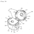
- Reference numeral 1 designates a safety cap, which is constituted of a cap main body 2 and a cover 20.
- an outer circumferential wall 11 is formed into a small-diameter portion 11a via an upward step 11b, and then, the upper surface of the small-diameter portion is closed by a top plate 3.
- an inner circumferential wall 10 fittable to the outer surface of a neck portion 52 of a container 51 is suspended down from the undersurface of the top plate, and further, a part of the top plate inward of the inner circumferential wall is raised in a semispherical shape, so that a pouring hole 4 is formed at the top of the raised portion. Otherwise, a seal cylinder to be fitted to the inner surface of the neck portion 52 may be suspended down from the surroundings of the pouring hole.
- the operating plate 6 On the outer circumferential wall 11 is disposed at least one operating plate 6 (or a pushbutton).
- a pair of operating plates should be disposed on both sides on the outer circumferential wall 11 in the cap main body with substantially equal intervals from a hinge, described later, as shown in FIGS. 1 to 4.
- the operating plate 6 is defined by a generally inverted U-shaped split groove 5 (or a separating line), so that the operating plate is formed in an inward elastically deformable manner while its lower end being fixed.
- the split groove 5 is extending vertically from the small-diameter portion 11a on the outer circumferential wall to a vertically intermediate portion of the same.
- engaging means 7 is additionally formed at the outer surface at a portion 6a at which the small-diameter portion is formed.
- the lower end of the operating plate 6 as a connecting portion 13 is continuous to the lower portion of the outer circumferential wall 11.
- the engaging means 7 may be an engaging projection oriented in a circumferential direction.
- the inverted U-shaped split groove 5 may extends from the right and left ends of the top plate 3 toward an intermediate portion of the outer circumferential wall 11 through the small-diameter portion 11a.
- the upper portion of the split groove serves as a cutout 8, which is cut out toward the center of the top plate.
- the operating plate 6 gradually becomes thicker upward from the lower end, and is disposed in such a manner as to protrude outward from the outline of the outer surface of the outer circumferential wall 11 except for the operating plate 6, as shown in FIGS. 1 and 2. Consequently, the position of the operating plate 6 can be recognized by a touch with a finger without visual perception.
- a fixing member 14 for fixing the operating plate which is constituted of an engaging piece 15 and an engaging piece receiver 16.
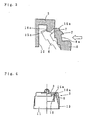
- the engaging piece serves as an upper end 15a of the operating plate 6, as shown in FIG. 2.
- the cutout 8 is formed in such a manner that the upper end is loosely fitted, and further, a projection 16a serving as the engaging piece receiver is formed at the lower surface of the peripheral edge of the cutout.
- the outer surface of the projection is inclined down inward, so that the operating plate upper end 15a rides over the projection 16a to thus engage with and be locked to the inner surface of the projection when the operating plate 6 is elastically deformed inward.
- engaging slots as engaging means 22 on the side of the cover are formed at both of the right and left of a peripheral wall 21 whose lower portion can detachably engage with the small-diameter portion 11a formed at the cap main body 2.
- the engaging projections serving as the engaging means 7 on the side of the operating plate are formed in such a manner as to be freely fitted into the engaging slots.
- an engaging cylinder 24 which can detachably engage with the outer surface of the raised portion with the pouring hole 4, described already, is suspended from the center of the lower surface of a cover plate 23 for closing the upper surface of the peripheral wall 21.
- a mouth on the peripheral wall 21 is connected to the periphery of the upward step at the cap main end via a hinge 25.
- the hinge should consist of a thin hinge and tension springs positioned on right and left sides of the hinge. The tension spring functions to hold the cover 20 in an open state shown in FIG. 1.
- reference numeral 26 designates an elastic locking plate projecting from the outer surface of the front portion of the small-diameter portion 11a on the outer circumferential wall in the cap main body.
- reference numeral 27 designates a stopper formed at the outer surface of the front portion on the peripheral wall 21 of the cover.
- reference numeral 28 designates an engaging portion additionally formed at the inner surface of the lower end of the front portion on the peripheral wall of the cover, wherein the engaging portion 28 can engage with the locking plate 26 by closing the cover.
- the upper portions of the right and left operating plates 6 are pressed inward to be thus elastically deformed, so that the engaging means 7 on the side of the operating plate are separated inward from the engaging means 22 on the side of the cover, and then, the cover 20 is rotated upward.
- the operating plate is stopped to be pressed at the time of abutment in normally opening the cover since the upper end 15a is formed in such a manner as to freely abut against the outer surface of the projection 16a when the operating plate 6 is pressed inward.
- the operation by the operating plate 6 in opening the cover is cumbersome.
- the engaging means 7 on the side of the operating plate are separated inward all the time from the engaging means 22 on the side of the cover.
- the operating plate 6 is pressed inward more strongly than when the cover is normally opened, so as to forcibly ride over the projection 16a.
- the upper end 15a of the operating plate is made to engage with the inner surface of the projection.
- the operating plate 6 is separated from the projection 16a. Incidentally, in the present embodiment, it is possible to release the engagement between the engaging means 7 and 22 and allow the operating plate upper end 15a to engage with the projection 16a by the single operation of pushing the operating plate 6 inward, thus achieving excellent ease of use.
- FIGS. 5 to 9 show a second embodiment according to the present invention.
- an engaging piece receiver 16 in fixing member 14 mainly is varied in the present embodiment. That is to say, as shown in FIG. 6, a pair of narrow cutouts 30 are formed at right and left ends of a top plate 3 in a cap main body in a manner corresponding to vertical groove portions of split grooves 5. Each of base ends at the top plate on both cutouts is formed as a thin bending line 31, the top plate between the cutouts is formed as an elastically bending plate 32, which can be bent downward, as indicated in FIG. 8. Furthermore, a slot 16b serving as an engaging piece receiver is bored at the bending plate. The slot is located at a position at which an engaging piece formed as an upper end 15a of the operating plate can be locked only when the elastically bending plate is bent and an operating plate 6 is elastically deformed inward.
- the operating plate upper end 15a may be loosely fitted into the slot 16b by bending the elastically bending plate 32 while pushing both of the operating plates 6 inward, so that the engaging means 7 on the side of the operating plate is held in a state separated from the engaging means 22 on the side of the cover.
- two operations that is, the operation of pushing the operating plate inward and the operation of bending the elastically bending plate 32 are required in order to release the engagement between the engaging means 7 and 22 all the time.
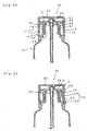
- FIGS. 10 and 11 show a third embodiment according to the present invention.
- cutouts 8 each having a width substantially corresponding to the upper end of an operating plate 6, are formed at right and left ends of a top plate 3, respectively, such that the upper end of the operating plate 6 is loosely fitted into the cutout.
- a tenon 15c projects inward from the intermediate portion in a width direction at the upper end of the operation plate and is so formed as to be narrower at its intermediate portion than a base end and a tip end.
- a tenon groove 16c formed into a shape in conformity with the projection and disposed at a corresponding position of the cutout 8 in the width direction.
- the tenon 15c is formed into a platelike projection having the outline of a C shape (or an arcuate shape), as viewed from the top.
- the intermediate portion of the tenon elastically pushes and enlarges its opening outwardly sideways of the tenon groove, to be thus snapped, as shown in FIG. 11.
- the tenon 15c abuts against the opening of the tenon groove 16c by pushing each of the operating plates 6 inward, and then, is fitted into the tenon groove. Moreover, for the purpose of prevention of another improper use, the tenon is detached outward of the tenon groove.
- the engagement between the engaging means 7 and 22 can be released and the tenon 15c can be fitted into the tenon groove 16c by a single operation of pushing the operating plate 6 inward, like in the first embodiment.
- the upper end of the operating plate 6 and the top plate 3 in a cap main body are integrally continuous to each other via the tenon and the tenon groove which are formed into complementary shapes, thereby achieving the good outside appearance of the cap in the cover opening state.
- FIGS. 12 to 16 show a fourth embodiment according to the present invention.
- an engaging piece 15 and an engaging piece receiver 16 are formed inward of an outer circumferential wall 11 of a cap main body 2.
- the engaging piece 15 and the engaging piece receiver 16 are formed at the inner surface of an operating plate 6 and the outer surface of an inner circumferential wall 10 facing the inner surface, respectively.
- FIG. 12 shows a fourth embodiment according to the present invention.
- an engaging piece 15 and an engaging piece receiver 16 are formed inward of an outer circumferential wall 11 of a cap main body 2.
- the engaging piece 15 and the engaging piece receiver 16 are formed at the inner surface of an operating plate 6 and the outer surface of an inner circumferential wall 10 facing the inner surface, respectively.
- an engaging projection 15d formed into a T-shape in cross section and longitudinally disposed at the outer surface of the inner circumferential wall 10 serves as the engaging piece, and further, an elastically deformable longitudinal rib 41 formed into a Y-shape in cross section is disposed at the inner surface of the operating plate, so that an engaging groove 16d additionally formed at the tip end of the longitudinal rib serves as the engaging piece receiver.
- the engaging projection 15d may be formed on the operating plate 6 while the engaging groove 16d may be formed on the inner circumferential wall 10, and otherwise, the engaging groove 16d may be formed directly at the outer surface of the inner circumferential wall 10 or the inner surface of the operating plate 6.
- the upper end of the operating plate 6 serving as a finger hook 42 projects upward of the top plate in the cap main body.
- the engaging projection 15d abuts against the opening of the engaging groove 16d by pushing the operating plate 6 inward, and then, the engaging projection 15d is fitted into the engaging groove 16d by further pushing the operating plate 6. Moreover, for the purpose of prevention of another improper use, a finger is hooked on the finger hook 42, thereby pushing outward and re-rotating the operating plate.
- the engaging piece 15 and the engaging piece receiver 16 are disposed inside of the outer circumferential wall 11 of the cap main body, it is possible to prevent the engagement with the engaging piece receiver from being released due to abutment of other members against the engaging piece. In addition, it is convenient because the engagement can be released only by operating the finger hook 42.
- FIGS. 17 to 22 show a fifth embodiment according to the present invention.
- the present embodiment is configured such that an operating plate 6 is fixed to a container 51.
- a pair of connecting portions 13 for connecting the operating plate to the cap main body except for the operating plate are disposed at both edges of the operating plate near the lower end of the operating plate 6 with a predetermined distance from the lower end, and further, a second projection 18 is additionally formed at the inner surface and the like of the operating plate under the connecting portion.
- a first projection 54 is additionally formed at a base outer surface of a top opened neck portion 52 with a space in a circumferential direction at substantially the same position as the second projection 18. A distance from the center axis of the neck portion to the outer surface of the first projection 54 is longer than that from the center axis of the cap main body 2 to the inner surface of the second projection 18. As indicated by an arrow in FIG. 18, when a safety cap 1 is rotated about the neck portion 52, the second projection 18 can ride on the tip end of the first projection 54.
- the first projection 54 and the second projection 18 constitute fixing member 14.
- the neck portion 52 is standing upwardly from the inner circumference of an inward flange 53 attached to the upper end of a body, and further, the pair of first projections 54 and 54 are additionally formed at the back and forth portions of the inward flange (that is, at positions deviated at 90° from the operating plates), respectively.
- the first projections may be formed at the back and forth portions of a raised portion 55 by raising the periphery of the inward flange. It is desirable that the inward flange 53 should be disposed in such a manner as to abut against or approach the lower end of an outer circumferential wall 11 when the cap main body is attached to the neck portion 52.
- a first engaging projection 56 is circumferentially disposed at the outer surface of the neck portion 52, and further, a second engaging projection 57 is circumferentially disposed at the inner surface of the inner circumferential wall, thereby allowing the second engaging projection 57 to engage with the lower surface of the first engaging projection 56 in the engaging state of the inner circumferential wall with the outer surface of the neck portion, so as to prevent any withdrawal of the cap.
- marks 58 and 58 may be formed under the first projections 54 and 54, respectively, or rotating range regulating means for the cap with respect to the container may be disposed, so that the second projection rides over the outer surface of the first projection when the cap is rotated up to one end of the regulating means.
- the lower portion of the operating plate 6 is pushed outward against the elasticity of the connecting portion 13 and the upper portion of the operating plate is pushed inward to be thus kept in a state disengaged from the engaging means by allowing the second projection 18 to ride over the outer surface of the first projection 54 by rotating the cap, thereby opening the cover 20 without performing the above-described operation.
- the cap main body need be rotated with respect to the neck portion of the container in order to secure the operating plate at an inward displaced position, a user cannot release the above-described safety device by erroneous operation. Furthermore, since the fixing member 14 is disposed inward of the outer circumferential wall 11 of the cap main body, the fixed state cannot be released by abutment of other members against the fixing means.
- FIGS. 22 and 23 show a modification of the present embodiments, wherein a single operating plate 6 is disposed on an outer circumferential wall 11 of a cap main body on an opposite side in a diametrical direction with respect to a hinge 25.
Landscapes
- Engineering & Computer Science (AREA)
- Chemical & Material Sciences (AREA)
- Ceramic Engineering (AREA)
- Mechanical Engineering (AREA)
- Materials Engineering (AREA)
- Structural Engineering (AREA)
- Organic Chemistry (AREA)
- Closures For Containers (AREA)
Abstract
Description
wherein the operating plate can be fixed to the cap main body or the container neck portion except for the operating plate by a fixing means for fixing the operating plate in the inward deformable state.
Claims (8)
- A safety cap for disposing a container comprising:wherein a pair of engaging means (7) and (22) engageable with each other are disposed at a peripheral wall of the cover and the operating plate (6), respectively, and further, the cover can be opened by releasing the engagement by elastically deforming the operating plate inward,a cap main body (2) having a top plate (3) with an pouring hole (4), and an outer circumferential wall (11) and an inner circumferential wall (10) for attachment to a container neck portion, said outer and inner circumferential walls being suspended from the top plate, and a part of the outer circumferential wall (11) being formed in an inward elastically deformable operating plate (6), at a peripheral edge of which a separation line is cut except its lower end or vicinity thereof remaining as a connection portion (13);a cover (20) connected to the upper portion of the cap main body via a hinge such that the cover is capable of putting thereon and removing therefrom;
wherein the operating plate (6) can be fixed to the cap main body (2) or the container neck portion (52) except for the operating plate by a fixing means for fixing the operating plate (14) in the inward deformable state. - A safety cap according to claim 1, wherein the lower end of the operating plate (6) is formed into the connection portion (13) serving as a fixing end, around which the operating plate can be disposed in a freely inward swingable manner as a whole.
- A safety cap according to claim 2, wherein the fixing member (14) includes an engaging piece (15) disposed at the operating plate (6), and an engaging piece receiver (16) disposed at the cap main body (2) except for the operating plate.
- A safety cap according to claim 3, wherein the engaging piece serves as an upper end (15a) of the operating plate, and further, the engaging piece receiver is a projection (16a) formed at an undersurface of the top plate outward of the inner circumferential wall (10).
- A safety cap according to claim 3, wherein the engaging piece serves as an upper end (15a) of the operating plate, and further, the engaging piece receiver (16) is disposed in an elastically bending plate (32) formed at an end of the top plate (3) near the operating plate in such a manner as to engage with the engaging piece (6) when the elastically bending plate is bent downward.
- A safety cap according to claim 3, wherein the engaging piece serves as a tenon (15c) protruding inward from the upper end of the operating plate (6) and being wider at its intermediate portion than a base end and tip end thereof, and further, the engaging piece receiver serves as a tenon groove (16c) having a shape in conformity with the tenon, cut out at an end of the top plate (3) near the operating plate.
- A safety cap according to claim 2, wherein the fixing member (14) is formed of an engaging projection (15d), which is longitudinally disposed at either one of an inner surface of the operating plate (6) and an opposite outer surface of the inner circumferential wall (10), and an engaging groove (16d), which is disposed at the other and can engage with the engaging projection (15d).
- A container with a safety cap having an erected top-opened neck portion (52) and the safety cap (1) disposed at the neck portion according to claim 1, the container comprising:wherein the second projection rides on the first projection when a cap main body (2) is rotated about the neck portion (52), so that the operating plate (6) is displaced inward against elasticity, so as to release the engagement between the engaging means (7) and (22).a pair of connecting portions (13) disposed at both side edges of an operating plate (6) near the lower end of the operating plate with a distance from the lower end;a second projection (18) in which the fixing member (14) is attached to the inner surface of the operating plate under the connecting portion; anda first projection (54) formed at a base outer surface of the neck portion with a distance from the second projection in a circumferential direction;
Applications Claiming Priority (5)
| Application Number | Priority Date | Filing Date | Title |
|---|---|---|---|
| JP2001261788A JP4027626B2 (en) | 2001-08-30 | 2001-08-30 | Container with safety cap |
| JP2001261788 | 2001-08-30 | ||
| JP2001264559A JP4039547B2 (en) | 2001-08-31 | 2001-08-31 | Safety cap |
| JP2001264559 | 2001-08-31 | ||
| PCT/JP2002/008831 WO2003018422A1 (en) | 2001-08-30 | 2002-08-30 | Safety cap and container with safety cap |
Publications (3)
| Publication Number | Publication Date |
|---|---|
| EP1505004A1 true EP1505004A1 (en) | 2005-02-09 |
| EP1505004A4 EP1505004A4 (en) | 2009-04-29 |
| EP1505004B1 EP1505004B1 (en) | 2012-07-11 |
Family
ID=26621312
Family Applications (1)
| Application Number | Title | Priority Date | Filing Date |
|---|---|---|---|
| EP02770181A Expired - Lifetime EP1505004B1 (en) | 2001-08-30 | 2002-08-30 | Safety cap and container with safety cap |
Country Status (3)
| Country | Link |
|---|---|
| US (2) | US20050133475A1 (en) |
| EP (1) | EP1505004B1 (en) |
| WO (1) | WO2003018422A1 (en) |
Cited By (6)
| Publication number | Priority date | Publication date | Assignee | Title |
|---|---|---|---|---|
| WO2007106840A2 (en) | 2006-03-15 | 2007-09-20 | Mcneil-Ppc, Inc. | Child-resistant container and container cap |
| ES2332979A1 (en) * | 2009-04-08 | 2010-02-15 | Seaplast S.A | Stank cap with folding cap for wide mouth packaging with robust opening system (Machine-translation by Google Translate, not legally binding) |
| WO2014111284A1 (en) * | 2013-01-16 | 2014-07-24 | Henkel Ag & Co. Kgaa | Container with closure device |
| WO2015111017A1 (en) * | 2014-01-24 | 2015-07-30 | RITCHY EU s.r.o. | Liquid containing bottle |
| WO2016072912A1 (en) * | 2014-11-03 | 2016-05-12 | Å&R Carton Lund Aktiebolag | Packaging container comprising a locking arrangement |
| DE102014117722A1 (en) | 2014-12-02 | 2016-06-02 | Sanner Gmbh | Container with child safety lock |
Families Citing this family (75)
| Publication number | Priority date | Publication date | Assignee | Title |
|---|---|---|---|---|
| US7481229B2 (en) * | 2002-11-06 | 2009-01-27 | L'oreal | Case with a sealing element |
| MY137973A (en) | 2003-10-31 | 2009-04-30 | Obrist Closures Switzerland | A tamper-evident closure |
| WO2005087604A1 (en) * | 2004-03-11 | 2005-09-22 | Alpla-Werke Alwin Lehner Gmbh & Co. Kg | Security rotating closure for a multi-compartment bottle, in particular for a dual-compartment bottle |
| US20080237236A1 (en) * | 2004-06-30 | 2008-10-02 | Roger Geoffrey Tanner | Dispensing Closure |
| US7798348B2 (en) * | 2005-12-02 | 2010-09-21 | Berry Plastics Corporation | Child-resistant closure |
| GB0608433D0 (en) * | 2006-04-28 | 2006-06-07 | Obrist Closures Switzerland | Closure with RFID device |
| ES2262450B1 (en) * | 2006-05-18 | 2007-09-16 | Seaplast, S.A. | "PLUG WITH FOLDING COVER FOR BOTTLES AND SIMILAR EQUIPPED WITH AN AUTOMATIC LID OPENING SYSTEM THAT INCLUDES AN IMPROVED BUTTON." |
| US20080164259A1 (en) * | 2007-01-04 | 2008-07-10 | Coe Matthew T | Container useful for holding multiple articles of manufacture |
| FR2924097A1 (en) * | 2007-03-26 | 2009-05-29 | Lindal France Soc Par Actions | CAP FOR SPRAYER. |
| US20080277368A1 (en) * | 2007-05-11 | 2008-11-13 | Alcan Global Pharmaceutical Packaging Inc. | Push-Squeeze-Lift Child-Resistant Closure And Container System |
| GB2450940B (en) * | 2007-07-13 | 2011-11-30 | Obrist Closures Switzerland | Tamper-evident closure |
| GB2450939B (en) | 2007-07-13 | 2012-02-01 | Obrist Closures Switzerland | Tamper-Evident closure |
| GB0721330D0 (en) * | 2007-10-31 | 2007-12-12 | Obrist Closures Switzerland | Tamper Evident closure |
| USD597410S1 (en) | 2008-01-29 | 2009-08-04 | Cvs Pharmacy, Inc. | Combined bottle and cap |
| US20100320168A1 (en) * | 2008-02-19 | 2010-12-23 | Martin Carey Bull | Child-resistant closure |
| US10919672B2 (en) * | 2008-03-31 | 2021-02-16 | Angelcare Feeding Usa, Llc | Seal indication mechanism for containers |
| GB0806190D0 (en) * | 2008-04-04 | 2008-05-14 | Obrist Closures Switzerland | A closure |
| EP2535291A1 (en) * | 2008-06-18 | 2012-12-19 | Polytop LLC | Dispensing closure |
| GB0816643D0 (en) * | 2008-09-11 | 2008-10-22 | Obrist Closures Switzerland | A closure |
| US9612995B2 (en) * | 2008-09-17 | 2017-04-04 | Adobe Systems Incorporated | Video viewer targeting based on preference similarity |
| CN101746567B (en) * | 2008-12-05 | 2011-08-17 | 友德塑胶(深圳)有限公司 | Double-flexible pipe container with one-way valves |
| GB0922117D0 (en) * | 2009-12-18 | 2010-02-03 | Obrist Closures Switzerland | A child-resistant closure |
| USD630093S1 (en) | 2010-06-11 | 2011-01-04 | Obrist Closures Switzerland Gmbh | Closure |
| GB201011143D0 (en) * | 2010-07-01 | 2010-08-18 | Rieke Corp | Dispensers |
| GB201011144D0 (en) | 2010-07-01 | 2010-08-18 | Rieke Corp | Dispensers |
| US8511492B2 (en) * | 2010-08-20 | 2013-08-20 | The Clorox Company | Bottle with handle venting inlet and child resistant flip-top closure with pouring spout and drainback hole |
| USD675060S1 (en) * | 2011-05-06 | 2013-01-29 | Thermos L.L.C. | Lid for drink container |
| US20120305581A1 (en) | 2011-06-03 | 2012-12-06 | Munchkin, Inc. | Cups for spillproof container assemblies |
| WO2012167215A2 (en) * | 2011-06-03 | 2012-12-06 | Munchkin, Inc. | Spillproof container assemblies |
| US8550269B2 (en) | 2011-06-08 | 2013-10-08 | Thermos L.L.C. | Drink bottle and lid with cover for drink spout |
| US8689978B2 (en) * | 2011-11-03 | 2014-04-08 | Berlin Packaging, Llc | Hinged container holder for medication cards |
| USD720622S1 (en) | 2011-11-30 | 2015-01-06 | Tc Heartland Llc | Bottle with cap |
| USD738732S1 (en) | 2011-11-30 | 2015-09-15 | Tc Heartland Llc | Bottle with cap |
| USD690558S1 (en) | 2012-05-22 | 2013-10-01 | Thermos L.L.C. | Drink bottle and lid including lockable lid cover |
| USD736634S1 (en) * | 2012-03-23 | 2015-08-18 | S.C. Johnson & Son, Inc. | Container with cap |
| USD736633S1 (en) * | 2012-03-23 | 2015-08-18 | S.C. Johnson & Son, Inc. | Container with cap |
| USD708521S1 (en) * | 2012-03-23 | 2014-07-08 | S.C. Johnson & Son, Inc. | Cap |
| USD727730S1 (en) * | 2012-03-23 | 2015-04-28 | S.C. Johnson & Son, Inc. | Cap |
| USD711231S1 (en) * | 2012-05-15 | 2014-08-19 | Plasticum Group B.V. | Flip-top cap |
| USD704001S1 (en) | 2012-05-21 | 2014-05-06 | Thermos L.L.C. | Drink bottle with smooth hand grip |
| USD686871S1 (en) | 2012-05-21 | 2013-07-30 | Thermos L.L.C. | Lid having fluted crown for drink bottle |
| GB201212042D0 (en) | 2012-07-05 | 2012-08-22 | Rieke Corp | Pump dispensers |
| EP2986528B1 (en) | 2013-04-17 | 2017-04-05 | CSP Technologies, Inc. | Container with button release |
| USD725966S1 (en) | 2013-05-20 | 2015-04-07 | Thermos L.L.C. | Combined drink bottle and lid |
| US9724629B2 (en) | 2013-05-20 | 2017-08-08 | Thermos L.L.C. | Bottle system and method for filtering or treating a beverage |
| US9834341B2 (en) * | 2013-06-19 | 2017-12-05 | Csp Technologies, Inc. | Cap and container assemblies |
| GB2519206B (en) * | 2013-08-17 | 2015-11-25 | Mwv Slatersville Llc | One-piece squeeze-to-dose dispensing closure |
| USD739183S1 (en) | 2014-03-31 | 2015-09-22 | Thermos L.L.C. | Beverage bottle with lid |
| US9327884B2 (en) | 2014-07-14 | 2016-05-03 | Gene R. Stull, SR. | Child-resistant flip-top closure |
| US9221585B1 (en) * | 2014-09-03 | 2015-12-29 | Yeo-Ming WANG | Cap closing structure |
| US9365329B1 (en) * | 2015-01-20 | 2016-06-14 | Tsung-Chih Chang | Container seal |
| USD778117S1 (en) * | 2015-02-12 | 2017-02-07 | Thermos K.K. | Beverage bottle |
| USD778118S1 (en) | 2015-02-12 | 2017-02-07 | Thermos K.K. | Beverage bottle |
| JP1565785S (en) | 2016-04-19 | 2016-12-19 | ||
| JP6767277B2 (en) * | 2017-02-08 | 2020-10-14 | 株式会社ジーシー | One-touch opening cap |
| RU2757439C2 (en) * | 2017-04-21 | 2021-10-15 | Капартис Аг | Corking means with cap |
| US10889416B2 (en) | 2017-04-24 | 2021-01-12 | Csp Technologies, Inc. | Child resistant container and method of opening same |
| US10961030B2 (en) | 2017-04-24 | 2021-03-30 | Csp Technologies, Inc. | Slidably openable child resistant container |
| US20190177044A1 (en) * | 2017-12-12 | 2019-06-13 | Hoffer Plastics Corporation | Tamper evident closure |
| GB201803224D0 (en) * | 2018-02-27 | 2018-04-11 | Compgen Ltd | A container with child resistant means |
| GB2588278B (en) * | 2018-03-09 | 2023-03-01 | M & M Ind Inc | Child resistant pail |
| USD935276S1 (en) | 2018-08-20 | 2021-11-09 | Thermos L.L.C. | Beverage bottle with lid |
| US11305922B2 (en) | 2018-10-29 | 2022-04-19 | Peter Barsoom | Child safe closure for a container |
| AU2019406613A1 (en) * | 2018-12-17 | 2021-06-10 | Glaxosmithkline Consumer Healthcare Holdings (Us) Llc | Child-resistant container |
| WO2020190490A1 (en) | 2019-03-15 | 2020-09-24 | Berry Global, Inc. | Pediatric dosing dispenser |
| CA3140974A1 (en) * | 2019-05-17 | 2020-11-26 | Cr Packaging Llc | Child-resistant and airtight container |
| US11040809B1 (en) * | 2020-10-09 | 2021-06-22 | Packaging Concepts Associates Holding, Inc. | Push button tilt top closure and locking system for a container |
| BR112023017918A2 (en) | 2021-03-10 | 2023-10-31 | Bericap Holding Gmbh | CONTAINER CLOSING SYSTEM |
| DE102021132116A1 (en) * | 2021-03-10 | 2022-03-31 | Bericap Holding Gmbh | ASEPTIC CLOSURE WITH A HINGE AND A MOUTHPIECE |
| US12351373B2 (en) * | 2021-05-12 | 2025-07-08 | Paul Bradley Forrest | Releasable container cap |
| US11542067B2 (en) * | 2021-05-12 | 2023-01-03 | Paul Bradley Forrest | Releasable container cap |
| CN121291933A (en) * | 2021-09-01 | 2026-01-09 | 贝里国际公司 | Packaging for storing and distributing fluids |
| CN118946506A (en) * | 2022-04-20 | 2024-11-12 | 贝里国际公司 | Child-resistant closures |
| WO2024092326A1 (en) * | 2022-11-01 | 2024-05-10 | Plastic Way Produtos Para Saude Epp | Locking bottle cap |
| US20250326540A1 (en) * | 2024-04-19 | 2025-10-23 | Berry Global, Inc. | Container for a package |
Family Cites Families (14)
| Publication number | Priority date | Publication date | Assignee | Title |
|---|---|---|---|---|
| JPS5628939Y2 (en) | 1976-07-22 | 1981-07-09 | ||
| DE2805046A1 (en) * | 1977-02-10 | 1978-08-17 | Createchnic Patent Ag | PLASTIC LATCH FOR FIXED AND DEFORMABLE CONTAINERS |
| GB8427925D0 (en) * | 1984-11-05 | 1984-12-12 | Johnsen Jorgensen Plastics Ltd | Child-resistant closure |
| DE3625477C2 (en) | 1986-07-28 | 1994-08-04 | Friedhoff & Mueller Fm Plast | Childproof hinged hinge closure for bottles or similar containers |
| US4752014A (en) * | 1987-12-16 | 1988-06-21 | Poly-Seal Corporation | Tamper-evident child-resistant closure and container with same |
| US5449077A (en) * | 1994-09-13 | 1995-09-12 | Seidler; David | Bottle with child resistant cap |
| JP3276532B2 (en) * | 1995-05-16 | 2002-04-22 | 株式会社ニフコ | Container cap |
| DE19531341A1 (en) * | 1995-08-25 | 1997-02-27 | Zeller Plastik Koehn Graebner | Closure |
| JP3517043B2 (en) | 1995-09-21 | 2004-04-05 | 株式会社吉野工業所 | Safety cap |
| JP3273359B2 (en) * | 1997-01-27 | 2002-04-08 | 武内プレス工業株式会社 | Container lid structure |
| JP3735643B2 (en) * | 1997-03-21 | 2006-01-18 | 株式会社吉野工業所 | Pouring cap |
| JP2000335610A (en) | 1999-05-26 | 2000-12-05 | Yoshino Kogyosho Co Ltd | Container having safety cap |
| JP3816693B2 (en) | 1999-05-31 | 2006-08-30 | 株式会社吉野工業所 | Container with safety cap |
| US6866164B2 (en) * | 2002-04-26 | 2005-03-15 | Rexam Medical Packaging Inc. | Child resistant dispenser |
-
2002
- 2002-08-30 EP EP02770181A patent/EP1505004B1/en not_active Expired - Lifetime
- 2002-08-30 US US10/496,964 patent/US20050133475A1/en not_active Abandoned
- 2002-08-30 WO PCT/JP2002/008831 patent/WO2003018422A1/en not_active Ceased
-
2010
- 2010-09-29 US US12/923,606 patent/US8469212B2/en not_active Expired - Fee Related
Cited By (11)
| Publication number | Priority date | Publication date | Assignee | Title |
|---|---|---|---|---|
| WO2007106840A2 (en) | 2006-03-15 | 2007-09-20 | Mcneil-Ppc, Inc. | Child-resistant container and container cap |
| WO2007106840A3 (en) * | 2006-03-15 | 2008-02-21 | Mcneil Ppc Inc | Child-resistant container and container cap |
| US8074821B2 (en) | 2006-03-15 | 2011-12-13 | Mcneil-Ppc, Inc. | Child-resistant container and container cap |
| KR101434590B1 (en) * | 2006-03-15 | 2014-08-27 | 맥네일-피피씨, 인코포레이티드 | Safety containers and containers for children |
| ES2332979A1 (en) * | 2009-04-08 | 2010-02-15 | Seaplast S.A | Stank cap with folding cap for wide mouth packaging with robust opening system (Machine-translation by Google Translate, not legally binding) |
| ES2332979B1 (en) * | 2009-04-08 | 2010-12-23 | Seaplast S.A | SEALED PLUG WITH FOLDING COVER FOR WIDE MOUTH PACKS WITH ROBUST OPENING SYSTEM. |
| WO2014111284A1 (en) * | 2013-01-16 | 2014-07-24 | Henkel Ag & Co. Kgaa | Container with closure device |
| WO2015111017A1 (en) * | 2014-01-24 | 2015-07-30 | RITCHY EU s.r.o. | Liquid containing bottle |
| WO2016072912A1 (en) * | 2014-11-03 | 2016-05-12 | Å&R Carton Lund Aktiebolag | Packaging container comprising a locking arrangement |
| DE102014117722A1 (en) | 2014-12-02 | 2016-06-02 | Sanner Gmbh | Container with child safety lock |
| WO2016087213A1 (en) | 2014-12-02 | 2016-06-09 | Sanner Gmbh | Container with child lock |
Also Published As
| Publication number | Publication date |
|---|---|
| WO2003018422A1 (en) | 2003-03-06 |
| EP1505004B1 (en) | 2012-07-11 |
| US20050133475A1 (en) | 2005-06-23 |
| US20110062107A1 (en) | 2011-03-17 |
| EP1505004A4 (en) | 2009-04-29 |
| US8469212B2 (en) | 2013-06-25 |
Similar Documents
| Publication | Publication Date | Title |
|---|---|---|
| US8469212B2 (en) | Safety cap and container with safety cap | |
| CA1235389A (en) | Child resistant closure and closure and container assembly | |
| JP4449725B2 (en) | Open bottle | |
| US5577626A (en) | Closure with opening assist feature | |
| US5727704A (en) | Child resistant cap and safety collar ring having unique boss arrangements | |
| JPS5810304B2 (en) | anzen cap | |
| JP2010195406A (en) | Container device | |
| EP0558218B1 (en) | Fastener for releasably fastening face guard to helmet | |
| EP1413524A1 (en) | Safety cap | |
| WO2020086442A1 (en) | Child resistant senior friendly can closure mechanism | |
| GB2320922A (en) | Disc container | |
| JPH0426343Y2 (en) | ||
| JP4056723B2 (en) | Safety cap with auxiliary lid | |
| JP4039547B2 (en) | Safety cap | |
| KR0132661Y1 (en) | Cap structure of container | |
| JP4293355B2 (en) | cap | |
| JP3986774B2 (en) | Safety cap with auxiliary lid | |
| KR100869636B1 (en) | safe vessel | |
| JP3770447B2 (en) | Pouring cap with lid | |
| JP2022057086A (en) | Cap, and container with cap | |
| JP2017088237A (en) | Portable beverage bottle | |
| JP7138978B2 (en) | Beverage container stopper and thermos bottle equipped with the same | |
| EP4527257B1 (en) | Cap unit and capped container | |
| JPH0454142Y2 (en) | ||
| JPH0141383Y2 (en) |
Legal Events
| Date | Code | Title | Description |
|---|---|---|---|
| PUAI | Public reference made under article 153(3) epc to a published international application that has entered the european phase |
Free format text: ORIGINAL CODE: 0009012 |
|
| 17P | Request for examination filed |
Effective date: 20040701 |
|
| AK | Designated contracting states |
Kind code of ref document: A1 Designated state(s): DE FR GB |
|
| A4 | Supplementary search report drawn up and despatched |
Effective date: 20090330 |
|
| 17Q | First examination report despatched |
Effective date: 20090710 |
|
| REG | Reference to a national code |
Ref country code: DE Ref legal event code: R079 Ref document number: 60243300 Country of ref document: DE Free format text: PREVIOUS MAIN CLASS: B65D0043220000 Ipc: B65D0047080000 |
|
| RIC1 | Information provided on ipc code assigned before grant |
Ipc: B65D 55/02 20060101ALI20110830BHEP Ipc: B65D 50/04 20060101ALI20110830BHEP Ipc: B65D 47/08 20060101AFI20110830BHEP |
|
| R17P | Request for examination filed (corrected) |
Effective date: 20040701 |
|
| GRAP | Despatch of communication of intention to grant a patent |
Free format text: ORIGINAL CODE: EPIDOSNIGR1 |
|
| GRAS | Grant fee paid |
Free format text: ORIGINAL CODE: EPIDOSNIGR3 |
|
| GRAA | (expected) grant |
Free format text: ORIGINAL CODE: 0009210 |
|
| AK | Designated contracting states |
Kind code of ref document: B1 Designated state(s): DE FR GB |
|
| REG | Reference to a national code |
Ref country code: GB Ref legal event code: FG4D |
|
| REG | Reference to a national code |
Ref country code: DE Ref legal event code: R096 Ref document number: 60243300 Country of ref document: DE Effective date: 20120906 |
|
| PLBE | No opposition filed within time limit |
Free format text: ORIGINAL CODE: 0009261 |
|
| STAA | Information on the status of an ep patent application or granted ep patent |
Free format text: STATUS: NO OPPOSITION FILED WITHIN TIME LIMIT |
|
| 26N | No opposition filed |
Effective date: 20130412 |
|
| REG | Reference to a national code |
Ref country code: DE Ref legal event code: R097 Ref document number: 60243300 Country of ref document: DE Effective date: 20130412 |
|
| REG | Reference to a national code |
Ref country code: FR Ref legal event code: PLFP Year of fee payment: 15 |
|
| PGFP | Annual fee paid to national office [announced via postgrant information from national office to epo] |
Ref country code: DE Payment date: 20160823 Year of fee payment: 15 Ref country code: GB Payment date: 20160824 Year of fee payment: 15 |
|
| PGFP | Annual fee paid to national office [announced via postgrant information from national office to epo] |
Ref country code: FR Payment date: 20160712 Year of fee payment: 15 |
|
| REG | Reference to a national code |
Ref country code: DE Ref legal event code: R119 Ref document number: 60243300 Country of ref document: DE |
|
| GBPC | Gb: european patent ceased through non-payment of renewal fee |
Effective date: 20170830 |
|
| REG | Reference to a national code |
Ref country code: FR Ref legal event code: ST Effective date: 20180430 |
|
| PG25 | Lapsed in a contracting state [announced via postgrant information from national office to epo] |
Ref country code: DE Free format text: LAPSE BECAUSE OF NON-PAYMENT OF DUE FEES Effective date: 20180301 Ref country code: GB Free format text: LAPSE BECAUSE OF NON-PAYMENT OF DUE FEES Effective date: 20170830 |
|
| PG25 | Lapsed in a contracting state [announced via postgrant information from national office to epo] |
Ref country code: FR Free format text: LAPSE BECAUSE OF NON-PAYMENT OF DUE FEES Effective date: 20170831 |