EP1504988A2 - Bicycle sprocket - Google Patents
Bicycle sprocket Download PDFInfo
- Publication number
- EP1504988A2 EP1504988A2 EP04016982A EP04016982A EP1504988A2 EP 1504988 A2 EP1504988 A2 EP 1504988A2 EP 04016982 A EP04016982 A EP 04016982A EP 04016982 A EP04016982 A EP 04016982A EP 1504988 A2 EP1504988 A2 EP 1504988A2
- Authority
- EP
- European Patent Office
- Prior art keywords
- sprocket
- bicycle
- ring part
- fastening
- crank
- Prior art date
- Legal status (The legal status is an assumption and is not a legal conclusion. Google has not performed a legal analysis and makes no representation as to the accuracy of the status listed.)
- Withdrawn
Links
Images




Classifications
-
- B—PERFORMING OPERATIONS; TRANSPORTING
- B62—LAND VEHICLES FOR TRAVELLING OTHERWISE THAN ON RAILS
- B62M—RIDER PROPULSION OF WHEELED VEHICLES OR SLEDGES; POWERED PROPULSION OF SLEDGES OR SINGLE-TRACK CYCLES; TRANSMISSIONS SPECIALLY ADAPTED FOR SUCH VEHICLES
- B62M9/00—Transmissions characterised by use of an endless chain, belt, or the like
- B62M9/04—Transmissions characterised by use of an endless chain, belt, or the like of changeable ratio
- B62M9/06—Transmissions characterised by use of an endless chain, belt, or the like of changeable ratio using a single chain, belt, or the like
- B62M9/10—Transmissions characterised by use of an endless chain, belt, or the like of changeable ratio using a single chain, belt, or the like involving different-sized wheels, e.g. rear sprocket chain wheels selectively engaged by the chain, belt, or the like
-
- B—PERFORMING OPERATIONS; TRANSPORTING
- B62—LAND VEHICLES FOR TRAVELLING OTHERWISE THAN ON RAILS
- B62K—CYCLES; CYCLE FRAMES; CYCLE STEERING DEVICES; RIDER-OPERATED TERMINAL CONTROLS SPECIALLY ADAPTED FOR CYCLES; CYCLE AXLE SUSPENSIONS; CYCLE SIDECARS, FORECARS, OR THE LIKE
- B62K19/00—Cycle frames
- B62K19/02—Cycle frames characterised by material or cross-section of frame members
- B62K19/16—Cycle frames characterised by material or cross-section of frame members the material being wholly or mainly of plastics
-
- B—PERFORMING OPERATIONS; TRANSPORTING
- B62—LAND VEHICLES FOR TRAVELLING OTHERWISE THAN ON RAILS
- B62M—RIDER PROPULSION OF WHEELED VEHICLES OR SLEDGES; POWERED PROPULSION OF SLEDGES OR SINGLE-TRACK CYCLES; TRANSMISSIONS SPECIALLY ADAPTED FOR SUCH VEHICLES
- B62M9/00—Transmissions characterised by use of an endless chain, belt, or the like
- B62M9/04—Transmissions characterised by use of an endless chain, belt, or the like of changeable ratio
- B62M9/06—Transmissions characterised by use of an endless chain, belt, or the like of changeable ratio using a single chain, belt, or the like
- B62M9/10—Transmissions characterised by use of an endless chain, belt, or the like of changeable ratio using a single chain, belt, or the like involving different-sized wheels, e.g. rear sprocket chain wheels selectively engaged by the chain, belt, or the like
- B62M9/105—Transmissions characterised by use of an endless chain, belt, or the like of changeable ratio using a single chain, belt, or the like involving different-sized wheels, e.g. rear sprocket chain wheels selectively engaged by the chain, belt, or the like involving front sprocket chain-wheels engaged by the chain, belt or the like
-
- F—MECHANICAL ENGINEERING; LIGHTING; HEATING; WEAPONS; BLASTING
- F16—ENGINEERING ELEMENTS AND UNITS; GENERAL MEASURES FOR PRODUCING AND MAINTAINING EFFECTIVE FUNCTIONING OF MACHINES OR INSTALLATIONS; THERMAL INSULATION IN GENERAL
- F16H—GEARING
- F16H55/00—Elements with teeth or friction surfaces for conveying motion; Worms, pulleys or sheaves for gearing mechanisms
- F16H55/02—Toothed members; Worms
- F16H55/06—Use of materials; Use of treatments of toothed members or worms to affect their intrinsic material properties
- F16H2055/065—Moulded gears, e.g. inserts therefor
-
- F—MECHANICAL ENGINEERING; LIGHTING; HEATING; WEAPONS; BLASTING
- F16—ENGINEERING ELEMENTS AND UNITS; GENERAL MEASURES FOR PRODUCING AND MAINTAINING EFFECTIVE FUNCTIONING OF MACHINES OR INSTALLATIONS; THERMAL INSULATION IN GENERAL
- F16H—GEARING
- F16H55/00—Elements with teeth or friction surfaces for conveying motion; Worms, pulleys or sheaves for gearing mechanisms
- F16H55/02—Toothed members; Worms
- F16H55/06—Use of materials; Use of treatments of toothed members or worms to affect their intrinsic material properties
Definitions
- the present invention generally relates to a bicycle sprocket. More specifically, the present invention relates to a bicycle sprocket configured to be mounted to a rotational drive unit such as a crank of a bicycle and to have a bicycle (drive-purpose) chain wrapped around the outside circumference thereof.
- a bicycle is generally provided with a drive unit or drive train having front and rear sprockets and a chain wrapped around the sprockets.
- the front sprocket(s) is provided on the gear crank of the bicycle and the rear sprocket(s) is provided on the free hub of the bicycle.
- This type of bicycle sprocket is made of such materials as the aluminum having the designation A2014P under the standard JIS H4000 (category) or the iron having the designation SPCC under the standard JIS G3141 (category).
- aluminum is used as the material in order to reduce the weight.
- the two pieces of the conventional bicycle sprocket just described are fastened together with crimp pins, as mentioned above. It is relatively easy for looseness or play to develop between the two pieces when the two pieces are fastened in this manner. A gap is also provided between the two pieces of the conventional sprocket in order to prevent deformation caused by the weather. Consequently, the rigidity between the sprocket ring part and the fastening part must be provided by the crimp pins alone. Thus, it is difficult to maintain a high rigidity. Furthermore, the manufacturing process becomes relatively complex because a step is necessary during which the crimp pins are inserted into the two members and then crimped.
- One object of the present invention is to provide a bicycle sprocket that is constructed of two different materials that is light weight, maintains rigidity, prevents looseness or play between the two materials, and can be fabricated with a simplified manufacturing process.
- a bicycle sprocket in accordance with one aspect of the present invention, includes a sprocket ring part and a fastening part.
- the sprocket ring part includes first and second lateral side surfaces with a plurality of sprocket teeth arranged around an outer periphery thereof.
- the sprocket ring part is constructed of metal.
- the fastening part is adapted to be fixedly coupled to a rotational drive unit of a bicycle.
- the fastening part is constructed of synthetic resin material that is at least partially molded integrally around the first and second lateral side surfaces of the sprocket ring part at an area located radially inwardly the sprocket teeth.
- the sprocket is configured to be mounted to a rotational drive unit such as a front crank of a bicycle and to have a bicycle (drive-purpose) chain wrapped around the outside circumference thereof.
- a rotational drive unit such as a front crank of a bicycle and to have a bicycle (drive-purpose) chain wrapped around the outside circumference thereof.
- the sprocket ring part (on which the sprocket teeth that mesh with the chain are formed) is made of a metal that can maintain its strength and the fastening part (which is fastened to the rotational drive unit) is made of lightweight synthetic resin.
- the fastening part is formed integrally with both lateral faces of the portion of the sprocket ring part that is located more radially inward of the portion where the sprocket teeth are formed.
- the sprocket ring part and the fastening part are fixed together by molding the fastening part integrally to both lateral faces of the sprocket ring part, looseness or play therebetween can be prevented and a high rigidity can be maintained between the sprocket ring part and the fastening part. Additionally, the manufacturing process can be simplified because it is not necessary to provide a step for installing and crimping crimp pins. Furthermore, the weight of the sprocket can be reduced because the fastening part is made of a synthetic resin.
- the bicycle sprocket ring part is provided with an anchor structure or anchor means that facilitates connection to the fastening part in a non-rotatable manner.
- the sprocket ring part and the fastening part are rigidly connected in a non-rotatable manner via the anchor structure (means), thereby increasing the rigidity even further.
- the sprocket anchor structure (means) includes a plurality of through holes formed such that they are spaced apart from one another in the circumferential direction of the sprocket ring part. With this sprocket, the fastening part is formed such that it passes through the through holes.
- the anchor structure (means) includes a plurality of protrusions and depressions formed such that they are spaced apart from one another in the circumferential direction of the sprocket ring part. With this sprocket, the fastening part is formed along the circumferentially arranged protrusions and depressions.
- the rotational drive unit to which the sprocket is configured to be coupled is a bicycle gear crank.
- the bicycle gear crank includes a crank connecting part and a plurality of arm parts.
- the crank connecting part is configured to connect in a non-rotatable manner to the bicycle crank shaft.
- the plurality of arm parts extend radially from the crank connecting part and have first fastening holes formed on the tip ends thereof.
- the fastening part has a ring part that is molded integrally with the sprocket ring part and a screw fastening part that extends radially inward from the ring part.
- the screw fastening part has a plurality of second fastening holes positioned such that they can be aligned with the first fastening holes of the bicycle gear crank.
- the fastening part is constructed of a resin containing carbon fiber.
- the resin is obtained by impregnating a polyamide-based synthetic resin with a carbon fiber filler. With this sprocket, the carbon fiber impregnation enables a higher degree of strength to be obtained than when the fastening part is made of synthetic resin alone.
- the sprocket ring part is constructed of an aluminum alloy and has an anodic oxide layer (e.g. anodized, oxidized porous aluminum, and/or alumilite layer) formed on the surface thereof.
- anodic oxide layer e.g. anodized, oxidized porous aluminum, and/or alumilite layer
- an annular diffusion layer of a fine triazine thiol powder is formed on both lateral faces of the sprocket ring part using an electro deposition method, and the fastening part is chemically bonded to the sprocket ring part by molding the fastening part integrally over the diffusion layer.
- the sprocket ring part is made by die punching a metal plate into a ring shape having the sprocket teeth on the outer circumference thereof.
- the manufacturing process for the sprocket ring part is simplified.
- a sprocket having a smaller diameter can be made simultaneously using the portion of the metal plate located radially inward of the portion used to make the sprocket ring part.
- the sprocket ring part is made by die punching a metal plate into a flat rope-like piece (i.e., a long metal strip) having the sprocket teeth arranged lengthwise on one side thereof and bending the rope-like piece into a ring shape in such a manner that the sprocket teeth face radially outward.
- a metal plate into a flat rope-like piece (i.e., a long metal strip) having the sprocket teeth arranged lengthwise on one side thereof and bending the rope-like piece into a ring shape in such a manner that the sprocket teeth face radially outward.
- the sprocket ring part and the fastening part are fixed together by molding the fastening part integrally to both lateral faces of the sprocket ring part, looseness can be prevented and a high rigidity can be maintained between the sprocket ring part and the fastening part. Additionally, the manufacturing process can be simplified because it is not necessary to provide a crimping step for installing crimp pins and crimping them. Furthermore, the weight of the sprocket can be reduced because the fastening part is made of a synthetic resin.
- FIG. 1 a bicycle 10 is illustrated in accordance with a first embodiment of the present invention.
- Figure 1 shows a road bike 10 having a drop-type handlebar unit 14.
- the road bike 10 has a diamond-shaped frame 11 that serves as the framework of the bicycle body.
- the frame 11 has a frame body 12 and a front fork 13.
- the front fork 13 is supported on a front part of the frame 12 such that it can rotate freely about an axis that is tilted slightly from vertical.
- the lower part of the front fork 13 is divided into two prongs.
- the bicycle 10 is also provided with a handlebar unit 14 connected to the front fork 13, a drive unit or drive train 15, a front wheel 16, a rear wheel 17 and front and rear brake devices 18 and 19.
- the drive train 15 is configured to convert the rider's pedaling force into driving force.
- the front wheel 16 is supported in a freely rotatable manner on the bottom end of the front fork 13.
- the rear wheel 17 is supported in a freely rotatable manner on a rear part of the frame body 12.
- the frame body 12 has a triangular shaped main or front triangle 20 and a rear triangle 21 arranged rearward of the front triangle 20.
- the front triangle 20 is formed by a top tube 25, a down tube 26, head tube 27 and a seat tube 28.
- the top tube 25 is arranged generally horizontally, while the down tube 26 is arranged below the top tube 25 such that it slants upward toward the front.
- the head tube 27 is joined to the front ends of the top tube 25 and the down tube 26, while the seat tube 28 extends diagonally upward and is joined to the rear ends of the top tube 25 and down tube 26.
- a seat post 33 having a saddle 32 fastened thereto is secured in the seat tube 28 in such a manner that its position can be adjusted up and down.
- a cylindrical hanger 29 ( Figure 3) is formed at the portion where the seat tube 28 and the down tube 26 join.
- the rear triangle 21 is formed by seat stays 30, chain stays 31 and the seat tube 28.
- the seat stays 30 are joined at their front ends to the seat tube 28 and extend diagonally downward as two separate prongs.
- the chain stays 31 extend rearward as two separate prongs from the bottom end of the seat tube 28 and are joined at their rear ends to the seat stays 30.
- the handlebar stem 35 of the handlebar unit 14 is fastened to the upper part of the front fork 13 in such a manner that its vertical position can be selectively adjusted up and down relative to the front fork 13.
- a handlebar 36 extends to the left and right and is curved at both ends.
- the handlebar 36 is fastened to the top end of the handlebar stem 35.
- Brake levers 38 provided with gear shifting capability are mounted to both ends of the handlebar 36.
- the drive unit 15 includes a front crank set or crank unit 41, a rear sprocket assembly or small gear unit 43, a chain 44, a front derailleur 45 and a rear derailleur 46.
- the crank set (crank unit) 41 is mounted on the hanger 29.
- the rear sprocket assembly (small gear unit) 43 mounted in a non-rotatable manner to the free hub of the rear wheel 17.
- the chain 44 is arranged on the crank set (gear crank unit) 41 and the rear sprocket assembly (small gear unit) 43 so as to extend therebetween.
- the front derailleur 45 is coupled to the rear triangle 21, while the rear derailleur 46 is coupled to the seat tube 28.
- the derailleur 45 and 46 function as a means of changing gears.
- the front derailleur 45 has a chain guide 45a through which the chain 44 passes.
- the crank set (crank unit) 41 basically includes a crank shaft 50 (Figure 3), a right crank arm (gear crank) 51 and a left crank arm (left crank) 52.
- the crank shaft 50 is supported in a freely rotatable manner in the hanger 29 of the frame 11.
- the right crank arm 51 is crimp-fastened to the right end of the crank shaft 50 and has a pedal 53 (Figure 1) mounted to its tip end, while the left crank arm 52 ( Figure 3) is fastened in a detachable manner to the left end of the crank shaft 50 with another pedal 53 mounted to its tip end such that the rider can provide a pedaling force to the drive train 15.
- crank shaft 50 is mounted in a freely rotatable manner in the hanger 29 by means of a bottom bracket 54 mounted in the hanger 29.
- the crank shaft 50 is a hollow pipe-shaped member made of a high-rigidity alloy, such as chromium-molybdenum steel.
- the radially inwardly facing surface of the left end of crank shaft 50 is provided with internal threads 55b so that the left crank arm 52 can be fastened thereto with a bolt 59.
- the bottom bracket 54 includes a left and right bearing housings 60 and 61, a cylindrical linking member 62, left and right ball bearings 63 and 64, and left and right cover members 65 and 66.
- the left and right bearing housings 60 and 61 are screwed into the ends of the hanger 29.
- the cylindrical linking member 62 is concentric with and links to the left and right bearing housings 60 and 61.
- the left and right ball bearings 63 and 64 are mounted in the left and right housings 60 and 61, respectively.
- the left and right cover members 65 and 66 are mounted between the crank shaft 50 and the inner rings of the left and right ball bearings 63 and 64, respectively.
- the ball bearings 63 and 64 are sealed bearings having seals installed between the inner ring and the outer ring and are injected with grease in advance of assembling the bottom bracket 54. Consequently, lubrication maintenance can be eliminated. Arranging the bearings 63 and 64 outside the hanger 29 enables the diameter of the crank shaft 50 to be increased and, as a result, the crank shaft 50 can be made lighter in weight while maintaining high strength and rigidity by making the crank shaft 50 hollow.
- the right crank arm (gear crank) 51 includes a crank connecting part or portion 75, five support arm parts or portions 76 and a main right crank arm part or portion 77.
- the crank connecting portion 75 has an engagement depression 78 that forms a circular space and mounts in a non-rotatable manner to the right end of the crank shaft 50.
- the five support arm portions 76 extend radially outwardly from the crank connecting portion 75 and are configured such that two sprockets 71 and 72 (one large and one small, respectively) can be mounted on the tip ends thereof.
- the main crank arm portion 77 is preferably integrally formed with the crank connecting portion 75 and the five support arm portions 76 such that the right main crank arm portion 77 fixed to the right end of the crank shaft 50.
- the tip ends of the support arm portions 76 are provided with mounting sections (parts) 76a for attaching the sprockets 71 and 72 thereto.
- the mounting sections 76a are recessed on opposite axial sides thereof to the other portions to form radial abutment surfaces.
- the sprockets 71 and 72 are mounted on both sides of the mounting sections 76a in such a manner that the sprockets 71 and 72 are concentric with respect to the crank shaft 50.
- each of the mounting sections 76a is provided with a first fastening hole 76b.
- the sprockets 71 and 72 can be fastened simultaneously to the mounting sections 76a with bolts 80 and nuts 81.
- the right main crank portion 77 has a hollow structure and is formed integrally with the crank connecting portion 75 and the support arm portions 76.
- the right crank portion 77 extends radially outwardly, while slanting slightly outward in the axial direction from the outside surface 75a of the crank connecting portion 75.
- a threaded pedal mounting hole 77a is provided in the extended tip end of the right crank portion 77 for installing a pedal 53.
- the engagement depression 78 of the crank connecting portion 75 is mounted to the second portion 56 of the crank shaft 50.
- the engagement depression 78 is formed to a length (i.e., depth) that is larger than the length of the second portion 56 and reaches almost to the outside surface 75a.
- the outside surface 75a of the crank connecting portion 75 and the main right crank portion 77 is smoothly curved and free of irregularities.
- the depth of the engagement depression 78 is shorter than the diameter of the second portion 56 of the crank shaft 50.
- the sprocket 71 in accordance with a preferred embodiment of the present invention basically includes a sprocket ring part 90 and a fastening part 91.
- the sprocket ring part 90 is made of metal (e.g. aluminum), while the fastening part 91 is made of synthetic resin, formed integrally with the sprocket ring part 90.
- the fastening part 91 is fastened to the right crank arm 51 ( Figures 2 and 3).
- the sprocket ring part 90 is a ring-shaped member having multiple (i.e. a plurality of) sprocket teeth 90a on the outside circumference thereof upon which the chain 44 ( Figure 1) is wrapped. As shown in Figure 6, multiple (i.e. a plurality of) circumferentially spaced through holes 90d are provided that extend between (first and second) lateral surfaces 90b and 90c of the sprocket ring part 90. The through holes 90d form an anchor structure (means) for rigidly connecting the fastening part 91 in a non-rotatable manner.
- the sprocket ring part 90 is made by die punching a metal plate into the ring shape having sprocket teeth 90a formed on the outside circumference thereof and through holes 90d are formed in both lateral faces 90b, 90c thereof.
- the fastening part 91 is preferably made of a polyamide-based synthetic resin impregnated with a reinforcing material (for example, a carbon fiber filler).
- the fastening part 91 is formed integrally around both lateral surfaces 90b and 90c of the sprocket ring part 90 at an area of the sprocket ring part 90 located radially inward of where the sprocket teeth 90a are formed.
- the fastening part 91 has a ring section (part) 91a and a screw fastening section (part) 91b.
- the ring section 91a is molded integrally around and through the sprocket ring part 90.
- the screw fastening section 91b extends radially inward from the ring section 91a.
- the screw fastening section 91b has a plurality of second fastening holes positioned such that they can be aligned with said first fastening holes.
- the ring section 91a is formed integrally such that it covers both lateral faces 90b and 90c as well as the radially inwardly facing surface 90e of the sprocket ring part 90.
- the ring section 91a is also formed integrally such that it extends through the through holes 90d.
- the screw fastening section 91b has a plurality (five) of arch elements (parts) 91c that arch radially inwardly from the radially inward facing surface of the ring section 91a to form a plurality (five) arm fastening flanges (parts) 91d formed on a middle portion of each arch element 9 1 c such that they project radially inwardly.
- the arm fastening flanges 91d are positioned to be aligned face to face with the mounting sections 76a on the tip ends of the support arm portions 76.
- Each of the arm fastening flanges 91d is provided with a countersunk second fastening hole 91e positioned to face one of the first fastening holes 76b.
- Bolts 80 are installed from the second fastening hole 91e side and fastened with nuts 81 from the first fastening hole 76b (i.e. the opposite side) side such that the two sprockets 71 and 72 are fixed to opposite faces or sides of the mounting sections 76a.
- the bolts 80 are hollow bolts having hexagonal sockets and the nuts 81 are hollow nuts having flanges.
- the bolts 80 and nuts 81 are well-known items used for positioning and fastening front sprockets.
- the sprocket 71 is manufactured using a process like that shown in Figure 7 in accordance with the present invention. In order to simplify the drawings of Figure 7, only the ring section 91a of the fastening part 91 is shown and the screw fastening section 91b is omitted. The manufacturing process for the sprocket 71 of the present invention will now be discussed in more detail.
- an aluminum plate is die punched to obtain a sprocket ring part 90 shaped as shown in Figures 4 and 6 in a conventional manner.
- an anodic oxide layer e.g. an anodized, oxidized porous aluminum, and/or alumilite layer
- An annular diffusion layer 93 of a fine triazine thiol powder is then formed on both lateral faces 90b and 90c of the sprocket ring part 90 using an electro deposition method.
- Each of these surface treatments are well known in the metal working/treating arts. Thus, each of these surface treatments will not be discussed and/or illustrated in detail herein, except as related to the present invention.
- the sprocket ring part 90 on which the diffusion layers 93 have been formed is then inserted into a mold 95 having an upper die 95a and a lower die 95b for molding the fastening part 91.
- the inside of the mold 95 holds the radially outermost area of the sprocket ring part 90 (i.e. the sprocket teeth 90a and the area slightly radially inwardly thereof), while forming a space 95c for forming the fastening part 91.
- the mold 95 is closed and the internal space 95c is filled with a molten polyamide-based synthetic resin that has been impregnated with a reinforcing material such as carbon fiber filler.
- the synthetic resin and the diffusion layer 93 undergo a chemical reaction such that the fastening part 91 and the sprocket ring part 90 are chemically bonded together.
- a sprocket 71 having a fastening part 91 that is molded integrally with the sprocket ring part 90 is completed.
- the sprocket ring part 90 and the fastening part 91 are fixed together by molding the fastening part 91 integrally (i.e., chemically, adhesively fixing) to both lateral faces 90b and 90c of the sprocket ring part 90, looseness can be prevented and a high rigidity can be maintained between the sprocket ring part 90 and the fastening part 91. Additionally, the manufacturing process can be simplified because it is not necessary to provide a riveting step for installing rivets or crimp pins and crimping them. Furthermore, the weight of the sprocket can be reduced because the fastening part 91 is made of a synthetic resin.
- the sprocket 72 has a ring part 72b with a plurality of sprocket teeth 72a extending outwardly therefrom and a fastening part 72c that is integrally formed with the ring part 72b as a one-piece, unitary member.
- the fastening part 72c projects radially inward from the inner circumference of the ring part 72b.
- the sprocket 72 is constructed of a metallic material (for example, aluminum) using a well-known sprocket design and manufacturing techniques.
- the fastening part 72c of the sprocket 72 and the fastening part 91 of the sprocket 71 are fastened simultaneously to the support arm portions 76.
- the left crank arm 52 has a hollow-structured left main crank arm part or portion 85 provided with a pedal mounting hole 85a for screw-installing a pedal 53 on the tip end thereof.
- the left crank arm 52 is provided with a slit (not shown) in the inner end thereof that mounts to the crank shaft 50.
- the left crank arm 52 is fastened securely to the crank shaft 50 by tightening two mounting bolts 57a and 57b (which are arranged in positions shown below the crank shaft 50 in Figure 3) such that the slit narrowed.
- the two mounting bolts 57a and 57b are, for example, hexagonal socket bolts inserted with their heads facing in opposite directions, respectively.
- the sprockets 71 and 72 are first mounted to the right crank arm 51.
- the sprockets 71 and 72 are 72 are arranged in the recessed areas of the mounting sections 76a such that the respective fastening holes 76b and 91e are aligned face to face with each other.
- the bolts 80 are installed from the sprocket 71 side (i.e., the outside) and the nuts are installed from the sprocket 72 side (i.e., the inside) as best understood from Figures 3 and 5.
- the sprockets 71 and 72 are then secured by turning the bolts 80 using an Allen wrench (key) while preventing the nuts 81 from turning using a special tool.
- the right crank arm 51 is crimp-fastened to the crank shaft 50.
- the right end of the crank shaft 50 is inserted into the engagement depression 78 of the right crank arm 51.
- a crimping tool is mounted from the left end of the crank shaft 50.
- crank shaft 50 With the crimping tool attached thereto, the crank shaft 50 and are, for example, mounted to a holding tool whose shape is matched to the shape of the outside surface of the crank connecting part 75 and the right crank 77 of the right crank arm 51. Then, the crimping tool is pressed with a pressing device. The right crank arm 51 is thereby crimp-fastened to the crank shaft 50.
Landscapes
- Engineering & Computer Science (AREA)
- Mechanical Engineering (AREA)
- Chemical & Material Sciences (AREA)
- Combustion & Propulsion (AREA)
- Transportation (AREA)
- Gears, Cams (AREA)
Abstract
Description
- The present invention generally relates to a bicycle sprocket. More specifically, the present invention relates to a bicycle sprocket configured to be mounted to a rotational drive unit such as a crank of a bicycle and to have a bicycle (drive-purpose) chain wrapped around the outside circumference thereof.
- A bicycle is generally provided with a drive unit or drive train having front and rear sprockets and a chain wrapped around the sprockets. The front sprocket(s) is provided on the gear crank of the bicycle and the rear sprocket(s) is provided on the free hub of the bicycle. This type of bicycle sprocket is made of such materials as the aluminum having the designation A2014P under the standard JIS H4000 (category) or the iron having the designation SPCC under the standard JIS G3141 (category). When a plurality of sprockets are mounted to the gear crank and free hub in order to provide multiple gears, aluminum is used as the material in order to reduce the weight.
- There are also known bicycle sprocket designs that reduce the weight even further by having a sprocket ring part that is made of aluminum and has the sprocket teeth formed thereon and a fastening part that is made of a carbon fiber material, attached to the inner circumference of the sprocket ring part, and fastened to the gear crank (see German Utility Model Publication No. 20218755). In the case of this sprocket, the fastening part and an inner circumferential portion of the sprocket ring part are fastened together by installing crimp pins in semicircular holes provided in the sprocket ring part and the fastening part. Since the sprocket is made using two separate members, a gap is provided between the sprocket ring part and the fastening part in order to prevent deformation caused by the effects of weather.
- In view of the above, it will be apparent to those skilled in the art from this disclosure that there exists a need for an improved bicycle sprocket. This invention addresses this need in the art as well as other needs, which will become apparent to those skilled in the art from this disclosure.
- The two pieces of the conventional bicycle sprocket just described are fastened together with crimp pins, as mentioned above. It is relatively easy for looseness or play to develop between the two pieces when the two pieces are fastened in this manner. A gap is also provided between the two pieces of the conventional sprocket in order to prevent deformation caused by the weather. Consequently, the rigidity between the sprocket ring part and the fastening part must be provided by the crimp pins alone. Thus, it is difficult to maintain a high rigidity. Furthermore, the manufacturing process becomes relatively complex because a step is necessary during which the crimp pins are inserted into the two members and then crimped.
- One object of the present invention is to provide a bicycle sprocket that is constructed of two different materials that is light weight, maintains rigidity, prevents looseness or play between the two materials, and can be fabricated with a simplified manufacturing process.
- In accordance with one aspect of the present invention, a bicycle sprocket is provided that includes a sprocket ring part and a fastening part. The sprocket ring part includes first and second lateral side surfaces with a plurality of sprocket teeth arranged around an outer periphery thereof. The sprocket ring part is constructed of metal. The fastening part is adapted to be fixedly coupled to a rotational drive unit of a bicycle. The fastening part is constructed of synthetic resin material that is at least partially molded integrally around the first and second lateral side surfaces of the sprocket ring part at an area located radially inwardly the sprocket teeth.
- The sprocket is configured to be mounted to a rotational drive unit such as a front crank of a bicycle and to have a bicycle (drive-purpose) chain wrapped around the outside circumference thereof.
- With this sprocket, the sprocket ring part (on which the sprocket teeth that mesh with the chain are formed) is made of a metal that can maintain its strength and the fastening part (which is fastened to the rotational drive unit) is made of lightweight synthetic resin. The fastening part is formed integrally with both lateral faces of the portion of the sprocket ring part that is located more radially inward of the portion where the sprocket teeth are formed. Since the sprocket ring part and the fastening part are fixed together by molding the fastening part integrally to both lateral faces of the sprocket ring part, looseness or play therebetween can be prevented and a high rigidity can be maintained between the sprocket ring part and the fastening part. Additionally, the manufacturing process can be simplified because it is not necessary to provide a step for installing and crimping crimp pins. Furthermore, the weight of the sprocket can be reduced because the fastening part is made of a synthetic resin.
- In accordance with a second aspect of the present invention, the bicycle sprocket ring part is provided with an anchor structure or anchor means that facilitates connection to the fastening part in a non-rotatable manner. With this sprocket, the sprocket ring part and the fastening part are rigidly connected in a non-rotatable manner via the anchor structure (means), thereby increasing the rigidity even further.
- In accordance with a third aspect of the present invention, the sprocket anchor structure (means) includes a plurality of through holes formed such that they are spaced apart from one another in the circumferential direction of the sprocket ring part. With this sprocket, the fastening part is formed such that it passes through the through holes.
- In accordance with a fourth aspect of the present invention, the anchor structure (means) includes a plurality of protrusions and depressions formed such that they are spaced apart from one another in the circumferential direction of the sprocket ring part. With this sprocket, the fastening part is formed along the circumferentially arranged protrusions and depressions.
- In accordance with a fifth aspect of the present invention, the rotational drive unit to which the sprocket is configured to be coupled is a bicycle gear crank. The bicycle gear crank includes a crank connecting part and a plurality of arm parts. The crank connecting part is configured to connect in a non-rotatable manner to the bicycle crank shaft. The plurality of arm parts extend radially from the crank connecting part and have first fastening holes formed on the tip ends thereof. The fastening part has a ring part that is molded integrally with the sprocket ring part and a screw fastening part that extends radially inward from the ring part. The screw fastening part has a plurality of second fastening holes positioned such that they can be aligned with the first fastening holes of the bicycle gear crank. With this sprocket, the sprockets that are mounted to the bicycle gear crank can be made lighter in weight while also maintaining rigidity and preventing looseness or play.
- In accordance with a sixth aspect of the present invention, the fastening part is constructed of a resin containing carbon fiber. The resin is obtained by impregnating a polyamide-based synthetic resin with a carbon fiber filler. With this sprocket, the carbon fiber impregnation enables a higher degree of strength to be obtained than when the fastening part is made of synthetic resin alone.
- In accordance with a seventh aspect of the present invention, the sprocket ring part is constructed of an aluminum alloy and has an anodic oxide layer (e.g. anodized, oxidized porous aluminum, and/or alumilite layer) formed on the surface thereof. With this sprocket, the weight can be reduced while maintaining the strength of the sprocket ring part.
- In accordance with an eighth aspect of the present invention, an annular diffusion layer of a fine triazine thiol powder is formed on both lateral faces of the sprocket ring part using an electro deposition method, and the fastening part is chemically bonded to the sprocket ring part by molding the fastening part integrally over the diffusion layer. With this sprocket, the sprocket ring part and the fastening part are strongly fixed to each other and the rigidity is increased even further because the fastening part and sprocket ring part are chemically bonded to each other.
- In accordance with a ninth aspect of the present invention, the sprocket ring part is made by die punching a metal plate into a ring shape having the sprocket teeth on the outer circumference thereof. With this sprocket, the manufacturing process for the sprocket ring part is simplified. Also, a sprocket having a smaller diameter can be made simultaneously using the portion of the metal plate located radially inward of the portion used to make the sprocket ring part.
- In accordance with a tenth aspect of the present invention, the sprocket ring part is made by die punching a metal plate into a flat rope-like piece (i.e., a long metal strip) having the sprocket teeth arranged lengthwise on one side thereof and bending the rope-like piece into a ring shape in such a manner that the sprocket teeth face radially outward. With this sprocket, although the manufacturing process for the sprocket ring part is slightly more complex, the shape of the portion of the metal plate used to make the sprocket ring part is simpler and a higher yield of sprocket ring parts can be obtained from each metal plate.
- With the present invention, since the sprocket ring part and the fastening part are fixed together by molding the fastening part integrally to both lateral faces of the sprocket ring part, looseness can be prevented and a high rigidity can be maintained between the sprocket ring part and the fastening part. Additionally, the manufacturing process can be simplified because it is not necessary to provide a crimping step for installing crimp pins and crimping them. Furthermore, the weight of the sprocket can be reduced because the fastening part is made of a synthetic resin.
- These and other objects, features, aspects and advantages of the present invention will become apparent to those skilled in the art from the following detailed description, which, taken in conjunction with the annexed drawings, discloses a preferred embodiment of the present invention.
- Referring now to the attached drawings which form a part of this original disclosure:
- Figure 1 is a side elevational view of bicycle having a front crank set with a sprocket in accordance with a preferred embodiment of the present invention mounted thereto;
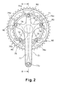
- Figure 2 is an enlarged side elevational view of the front crank set of the bicycle illustrated in Figure 1;
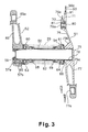
- Figure 3 is a partial, transverse, cross sectional view of the front crank set illustrated in Figures 1 and 2, as seen along section line III-III of Figure 2;
- Figure 4 is side elevational view of the large sprocket of the front crank set illustrated in Figures 1-3, with the other parts of the crank set removed for the purpose of illustration;
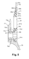
- Figure 5 is an enlarged, partial cross sectional view of the sprocket illustrated in Figure 4, as seen along section line V-V of Figure 4, with the right crank arm of the crank set coupled thereto for the purpose of illustration;
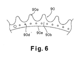
- Figure 6 is an enlarged partial side elevational view of the sprocket ring part of the sprocket illustrated in Figure 4, in order to illustrate the arrangement of through holes of the sprocket ring part;
- Figure 7 is a diagrammatic view illustrating a manufacturing process for a sprocket in accordance with the present invention;
- Figure 8(a) is an enlarged, partial side elevational view of a sprocket ring part (equivalent to the view of Figure 6) for a modified sprocket in accordance with another preferred embodiment of the present invention;
- Figure 8(b) is a side elevational view of a modified right crank arm with a modified sprocket utilizing the sprocket ring part illustrated in Figure 8(a) in accordance with the present invention; and
- Figure 9 is a diagrammatic view illustrating another manufacturing process in accordance with the present invention.
-
- Selected embodiments of the present invention will now be explained with reference to the drawings. It will be apparent to those skilled in the art from this disclosure that the following descriptions of the embodiments of the present invention are provided for illustration only and not for the purpose of limiting the invention as defined by the appended claims and their equivalents.
- Referring initially to Figure 1, a
bicycle 10 is illustrated in accordance with a first embodiment of the present invention. As an example of abicycle 10 that employs an embodiment of the present invention, Figure 1 shows aroad bike 10 having a drop-type handlebar unit 14. Theroad bike 10 has a diamond-shapedframe 11 that serves as the framework of the bicycle body. Theframe 11 has aframe body 12 and afront fork 13. Thefront fork 13 is supported on a front part of theframe 12 such that it can rotate freely about an axis that is tilted slightly from vertical. The lower part of thefront fork 13 is divided into two prongs. Thebicycle 10 is also provided with ahandlebar unit 14 connected to thefront fork 13, a drive unit or drivetrain 15, afront wheel 16, arear wheel 17 and front andrear brake devices 18 and 19. Thedrive train 15 is configured to convert the rider's pedaling force into driving force. Thefront wheel 16 is supported in a freely rotatable manner on the bottom end of thefront fork 13. Therear wheel 17 is supported in a freely rotatable manner on a rear part of theframe body 12. - The
frame body 12 has a triangular shaped main orfront triangle 20 and arear triangle 21 arranged rearward of thefront triangle 20. Thefront triangle 20 is formed by atop tube 25, adown tube 26,head tube 27 and aseat tube 28. Thetop tube 25 is arranged generally horizontally, while thedown tube 26 is arranged below thetop tube 25 such that it slants upward toward the front. Thehead tube 27 is joined to the front ends of thetop tube 25 and thedown tube 26, while theseat tube 28 extends diagonally upward and is joined to the rear ends of thetop tube 25 and downtube 26. Aseat post 33 having asaddle 32 fastened thereto is secured in theseat tube 28 in such a manner that its position can be adjusted up and down. A cylindrical hanger 29 (Figure 3) is formed at the portion where theseat tube 28 and thedown tube 26 join. Therear triangle 21 is formed by seat stays 30, chain stays 31 and theseat tube 28. The seat stays 30 are joined at their front ends to theseat tube 28 and extend diagonally downward as two separate prongs. The chain stays 31 extend rearward as two separate prongs from the bottom end of theseat tube 28 and are joined at their rear ends to the seat stays 30. - The handlebar stem 35 of the
handlebar unit 14 is fastened to the upper part of thefront fork 13 in such a manner that its vertical position can be selectively adjusted up and down relative to thefront fork 13. Ahandlebar 36 extends to the left and right and is curved at both ends. Thehandlebar 36 is fastened to the top end of thehandlebar stem 35. Brake levers 38 provided with gear shifting capability are mounted to both ends of thehandlebar 36. - The
drive unit 15 includes a front crank set or crankunit 41, a rear sprocket assembly orsmall gear unit 43, achain 44, afront derailleur 45 and arear derailleur 46. The crank set (crank unit) 41 is mounted on thehanger 29. The rear sprocket assembly (small gear unit) 43 mounted in a non-rotatable manner to the free hub of therear wheel 17. Thechain 44 is arranged on the crank set (gear crank unit) 41 and the rear sprocket assembly (small gear unit) 43 so as to extend therebetween. Thefront derailleur 45 is coupled to therear triangle 21, while therear derailleur 46 is coupled to theseat tube 28. Thederailleurs front derailleur 45 has achain guide 45a through which thechain 44 passes. - As shown in Figures 1-3, the crank set (crank unit) 41 basically includes a crank shaft 50 (Figure 3), a right crank arm (gear crank) 51 and a left crank arm (left crank) 52. The
crank shaft 50 is supported in a freely rotatable manner in thehanger 29 of theframe 11. Theright crank arm 51 is crimp-fastened to the right end of thecrank shaft 50 and has a pedal 53 (Figure 1) mounted to its tip end, while the left crank arm 52 (Figure 3) is fastened in a detachable manner to the left end of thecrank shaft 50 with another pedal 53 mounted to its tip end such that the rider can provide a pedaling force to thedrive train 15. - As shown in Figure 3, the
crank shaft 50 is mounted in a freely rotatable manner in thehanger 29 by means of abottom bracket 54 mounted in thehanger 29. Thecrank shaft 50 is a hollow pipe-shaped member made of a high-rigidity alloy, such as chromium-molybdenum steel. The radially inwardly facing surface of the left end ofcrank shaft 50 is provided with internal threads 55b so that theleft crank arm 52 can be fastened thereto with abolt 59. - The
bottom bracket 54 includes a left andright bearing housings cylindrical linking member 62, left andright ball bearings right cover members right bearing housings hanger 29. Thecylindrical linking member 62 is concentric with and links to the left andright bearing housings right ball bearings right housings right cover members crank shaft 50 and the inner rings of the left andright ball bearings - The
ball bearings bottom bracket 54. Consequently, lubrication maintenance can be eliminated. Arranging thebearings hanger 29 enables the diameter of thecrank shaft 50 to be increased and, as a result, thecrank shaft 50 can be made lighter in weight while maintaining high strength and rigidity by making the crankshaft 50 hollow. - As shown in Figures 2 and 3, the right crank arm (gear crank) 51 includes a crank connecting part or
portion 75, five support arm parts orportions 76 and a main right crank arm part orportion 77. Thecrank connecting portion 75 has anengagement depression 78 that forms a circular space and mounts in a non-rotatable manner to the right end of thecrank shaft 50. The fivesupport arm portions 76 extend radially outwardly from thecrank connecting portion 75 and are configured such that twosprockets 71 and 72 (one large and one small, respectively) can be mounted on the tip ends thereof. The maincrank arm portion 77 is preferably integrally formed with thecrank connecting portion 75 and the fivesupport arm portions 76 such that the right main crankarm portion 77 fixed to the right end of thecrank shaft 50. - The tip ends of the
support arm portions 76 are provided with mounting sections (parts) 76a for attaching thesprockets sections 76a are recessed on opposite axial sides thereof to the other portions to form radial abutment surfaces. Thus, thesprockets sections 76a in such a manner that thesprockets crank shaft 50. As shown in Figure 5, each of the mountingsections 76a is provided with afirst fastening hole 76b. Thus, thesprockets sections 76a withbolts 80 and nuts 81. - As shown in Figure 3, the right main crank
portion 77 has a hollow structure and is formed integrally with thecrank connecting portion 75 and thesupport arm portions 76. Theright crank portion 77 extends radially outwardly, while slanting slightly outward in the axial direction from theoutside surface 75a of thecrank connecting portion 75. A threadedpedal mounting hole 77a is provided in the extended tip end of theright crank portion 77 for installing apedal 53. - As shown in Figure 3, the
engagement depression 78 of thecrank connecting portion 75 is mounted to the second portion 56 of thecrank shaft 50. Theengagement depression 78 is formed to a length (i.e., depth) that is larger than the length of the second portion 56 and reaches almost to theoutside surface 75a. As a result, theoutside surface 75a of thecrank connecting portion 75 and the main right crankportion 77 is smoothly curved and free of irregularities. Also, the depth of theengagement depression 78 is shorter than the diameter of the second portion 56 of thecrank shaft 50. - As shown in Figures 4-6, the
sprocket 71 in accordance with a preferred embodiment of the present invention basically includes asprocket ring part 90 and afastening part 91. Thesprocket ring part 90 is made of metal (e.g. aluminum), while thefastening part 91 is made of synthetic resin, formed integrally with thesprocket ring part 90. Thefastening part 91 is fastened to the right crank arm 51 (Figures 2 and 3). - The
sprocket ring part 90 is a ring-shaped member having multiple (i.e. a plurality of)sprocket teeth 90a on the outside circumference thereof upon which the chain 44 (Figure 1) is wrapped. As shown in Figure 6, multiple (i.e. a plurality of) circumferentially spaced throughholes 90d are provided that extend between (first and second) lateral surfaces 90b and 90c of thesprocket ring part 90. The throughholes 90d form an anchor structure (means) for rigidly connecting thefastening part 91 in a non-rotatable manner. Thesprocket ring part 90 is made by die punching a metal plate into the ring shape havingsprocket teeth 90a formed on the outside circumference thereof and throughholes 90d are formed in both lateral faces 90b, 90c thereof. - The
fastening part 91 is preferably made of a polyamide-based synthetic resin impregnated with a reinforcing material (for example, a carbon fiber filler). Thefastening part 91 is formed integrally around bothlateral surfaces sprocket ring part 90 at an area of thesprocket ring part 90 located radially inward of where thesprocket teeth 90a are formed. Thefastening part 91 has a ring section (part) 91a and a screw fastening section (part) 91b. Thering section 91a is molded integrally around and through thesprocket ring part 90. Thescrew fastening section 91b extends radially inward from thering section 91a. Thescrew fastening section 91b has a plurality of second fastening holes positioned such that they can be aligned with said first fastening holes. Thering section 91a is formed integrally such that it covers both lateral faces 90b and 90c as well as the radially inwardly facingsurface 90e of thesprocket ring part 90. Thering section 91a is also formed integrally such that it extends through the throughholes 90d. Thescrew fastening section 91b has a plurality (five) of arch elements (parts) 91c that arch radially inwardly from the radially inward facing surface of thering section 91a to form a plurality (five) arm fastening flanges (parts) 91d formed on a middle portion of each arch element 9 1 c such that they project radially inwardly. Thearm fastening flanges 91d are positioned to be aligned face to face with the mountingsections 76a on the tip ends of thesupport arm portions 76. Each of thearm fastening flanges 91d is provided with a countersunksecond fastening hole 91e positioned to face one of thefirst fastening holes 76b.Bolts 80 are installed from thesecond fastening hole 91e side and fastened withnuts 81 from thefirst fastening hole 76b (i.e. the opposite side) side such that the twosprockets sections 76a. Thebolts 80 are hollow bolts having hexagonal sockets and the nuts 81 are hollow nuts having flanges. Thebolts 80 andnuts 81 are well-known items used for positioning and fastening front sprockets. - The
sprocket 71 is manufactured using a process like that shown in Figure 7 in accordance with the present invention. In order to simplify the drawings of Figure 7, only thering section 91a of thefastening part 91 is shown and thescrew fastening section 91b is omitted. The manufacturing process for thesprocket 71 of the present invention will now be discussed in more detail. - First, an aluminum plate is die punched to obtain a
sprocket ring part 90 shaped as shown in Figures 4 and 6 in a conventional manner. Preferably, an anodic oxide layer (e.g. an anodized, oxidized porous aluminum, and/or alumilite layer) is then formed on the surface of thesprocket ring part 90. Anannular diffusion layer 93 of a fine triazine thiol powder is then formed on both lateral faces 90b and 90c of thesprocket ring part 90 using an electro deposition method. Each of these surface treatments are well known in the metal working/treating arts. Thus, each of these surface treatments will not be discussed and/or illustrated in detail herein, except as related to the present invention. Thesprocket ring part 90 on which the diffusion layers 93 have been formed is then inserted into amold 95 having anupper die 95a and alower die 95b for molding thefastening part 91. The inside of themold 95 holds the radially outermost area of the sprocket ring part 90 (i.e. thesprocket teeth 90a and the area slightly radially inwardly thereof), while forming aspace 95c for forming thefastening part 91. After thesprocket ring part 90 is positioned, themold 95 is closed and theinternal space 95c is filled with a molten polyamide-based synthetic resin that has been impregnated with a reinforcing material such as carbon fiber filler. The synthetic resin and thediffusion layer 93 undergo a chemical reaction such that thefastening part 91 and thesprocket ring part 90 are chemically bonded together. Thus, by using an insert molding technique, asprocket 71 having afastening part 91 that is molded integrally with thesprocket ring part 90 is completed. - Since the
sprocket ring part 90 and thefastening part 91 are fixed together by molding thefastening part 91 integrally (i.e., chemically, adhesively fixing) to both lateral faces 90b and 90c of thesprocket ring part 90, looseness can be prevented and a high rigidity can be maintained between thesprocket ring part 90 and thefastening part 91. Additionally, the manufacturing process can be simplified because it is not necessary to provide a riveting step for installing rivets or crimp pins and crimping them. Furthermore, the weight of the sprocket can be reduced because thefastening part 91 is made of a synthetic resin. - The
sprocket 72 has aring part 72b with a plurality ofsprocket teeth 72a extending outwardly therefrom and afastening part 72c that is integrally formed with thering part 72b as a one-piece, unitary member. Thefastening part 72c projects radially inward from the inner circumference of thering part 72b. Thesprocket 72 is constructed of a metallic material (for example, aluminum) using a well-known sprocket design and manufacturing techniques. Thefastening part 72c of thesprocket 72 and thefastening part 91 of thesprocket 71 are fastened simultaneously to thesupport arm portions 76. - As shown in Figure 3, the left crank
arm 52 has a hollow-structured left main crank arm part orportion 85 provided with apedal mounting hole 85a for screw-installing a pedal 53 on the tip end thereof. Theleft crank arm 52 is provided with a slit (not shown) in the inner end thereof that mounts to thecrank shaft 50. Theleft crank arm 52 is fastened securely to thecrank shaft 50 by tightening two mountingbolts crank shaft 50 in Figure 3) such that the slit narrowed. The two mountingbolts - When mounting the crank set (crank unit) 41 configured as disclosed herein is mounted to the
bottom bracket 54, thesprockets right crank arm 51. When thesprockets right crank arm 51, thesprockets 71 are 72 are arranged in the recessed areas of the mountingsections 76a such that therespective fastening holes bolts 80 are installed from thesprocket 71 side (i.e., the outside) and the nuts are installed from thesprocket 72 side (i.e., the inside) as best understood from Figures 3 and 5. Thesprockets bolts 80 using an Allen wrench (key) while preventing the nuts 81 from turning using a special tool. After thesprockets right crank arm 51 is crimp-fastened to thecrank shaft 50. In order to perform crimp-fastening, the right end of thecrank shaft 50 is inserted into theengagement depression 78 of theright crank arm 51. Then, a crimping tool is mounted from the left end of thecrank shaft 50. With the crimping tool attached thereto, thecrank shaft 50 and are, for example, mounted to a holding tool whose shape is matched to the shape of the outside surface of thecrank connecting part 75 and the right crank 77 of theright crank arm 51. Then, the crimping tool is pressed with a pressing device. Theright crank arm 51 is thereby crimp-fastened to thecrank shaft 50. -
- (a) Referring to Figures 8(a) and 8(b), another embodiment of the present invention
will now be discussed in more detail. In the previous embodiment the anchor structure
(means) of the
sprocket ring part 90 comprised multiple circumferentially-spaced throughholes 90d provided in the lateral faces 90b (as shown in Figure 6). However, it is also acceptable to replace thesprocket ring part 90 with a modified sprocket ring part 90' that has a modified anchor structure (means) at the inner circumference thereof that includes multiple protrusions anddepressions 90f that are circumferentially arranged on the radially inward facingsurface 90e' of the sprocket ring part 90' (as shown in Figure 8(a)). In other words, the sprocket ring part of the present invention can have the configuration shown in Figure 6 and/or the configuration shown in Figure 8(a) about its entire inner circumference. The modified sprocket ring part 90' is identical to thesprocket ring part 90, except the sprocket ring part 90' is preferably provided with the multiple protrusions anddepressions 90f (Figure 8(a)) instead of theholes 90d (Figure 6), as mentioned above. Thus, the sprocket ring part 90' will not be discussed and/or illustrated in detail herein. Rather, it will be apparent to those skilled in the art from this disclosure that the descriptions and illustrations of thesprocket ring part 90 also apply to the modified sprocket ring part 90', except as explained and illustrated herein. Moreover, it will be apparent to those skilled in the art from this disclosure that the sprocket ring part 90' is configured to be used in place of thesprocket ring part 90 to form a modified sprocket 71' of a modified right crank arm 51', as seen in Figure 8(b). In view of the similarities between thesprocket ring parts 90 and 90' identical reference numerals will be used to identify identical parts, while identical reference numerals with a prime (') will be used to identify modified parts of the sprocket ring part 90'. The right crank arm 51' and the sprocket 71' are identical to theright crank arm 51 and thesprocket 71 of the previous embodiment, except for the use of the modified sprocket ring part 90'. In any case, it will be apparent to those skilled in the art from this disclosure that the sprocket ring part of the present invention preferably includes an anchor structure (means) to facilitate a tight connection with thefastening part 91. - (b) Although the previous embodiments described examples of a sprockets for a road bike, the present invention can be applied to any bicycle.
- (c) Although the previous embodiments described examples of a sprockets
configured to be mounted to a crank unit (crank set) 41 whose right crank arm 51 (51') is
crimp-fastened to the
crank shaft 50 that has the form of a hollow cylinder over its entire length, the present invention can also be applied to a sprocket configured to be mounted to a crank unit whose gear crank is bolt-fastened to the crank shaft or a crank unit having a separate right crank that is bolt-fastened to the crank shaft together with the gear crank. The present invention can also be applied to a sprocket configured to be mounted to the small (rear sprocket assembly)gear unit 43. Furthermore, it is acceptable for thesprocket 72, to also include a sprocket ring part made of an aluminum alloy and a fastening part made of a synthetic resin. In other words, while the features of the sprockets 71 (71') and the manufacturing techniques utilized to make the sprockets 71 (71') are particularly useful for the largest sprocket because it is typically heavier than smaller sprockets, it will be apparent to those skilled in the art from this disclosure that the present invention can be applied to any sized sprocket where the advantages of the present invention are desirable. - (d) Although in the previous embodiments the sprocket ring part 90 (90') is
constructed of aluminum and the
fastening part 91 is constructed of a polyamide-based synthetic resin, it will be apparent to those skilled in the art from this disclosure that it is acceptable for the sprocket ring part 90 (90') to be made of any other lightweight metallic material and for thefastening part 91 to be made of any other lightweight synthetic resin as needed and/or desired. - (e) Although in the previous embodiments the sprocket ring part 90 (90') is made by
die punching an aluminum plate (metal plate) into the desired shape with the desired anchor
structure (means), it will be apparent to those skilled in the art from this disclosure that it is
also acceptable to fabricate the sprocket ring part 90 (90') as shown in Figure 9 by die
punching a
metal plate 96 into a flat rope-like piece having thesprocket teeth 90a arranged lengthwise on one side thereof and the anchor structure (means) along the opposite side, and then bending the rope-like piece into a ring shape in such a manner that thesprocket teeth 90a face radially outward and the anchor structure (means) is arranged radially inwardly. In such a case, agap 90g is formed in the sprocket ring part 90 (90'). It is acceptable to either join thegap 90g by welding or crimping or to leave the gap unjoined. Even if thegap 90g is left unjoined, it is unlikely that the gap will cause a problem because the sprocket ring part 90 (90') is fixed to thefastening part 91 by the integral molding of thefastening part 91 described above. -
- As used herein, the following directional terms "forward, rearward, above, downward, vertical, horizontal, below and transverse" as well as any other similar directional terms refer to those directions of a bicycle equipped with the present invention. Accordingly, these terms, as utilized to describe the present invention should be interpreted relative to a bicycle equipped with the present invention.
- The terms of degree such as "substantially", "about" and "approximately" as used herein mean a reasonable amount of deviation of the modified term such that the end result is not significantly changed. These terms should be construed as including a deviation of at least ± 5% of the modified term if this deviation would not negate the meaning of the word it modifies.
- This application claims priority to Japanese Patent Application No. 2003-288331. The entire disclosure of Japanese Patent Application No. 2003-288331 is hereby incorporated herein by reference.
- While only selected embodiments have been chosen to illustrate the present invention, it will be apparent to those skilled in the art from this disclosure that various changes and modifications can be made herein without departing from the scope of the invention as defined in the appended claims. Furthermore, the foregoing descriptions of the embodiments according to the present invention are provided for illustration only, and not for the purpose of limiting the invention as defined by the appended claims and their equivalents.
Claims (13)
- A bicycle sprocket comprising:a sprocket ring part (90, 90') including first and second lateral side surfaces with a plurality of sprocket teeth arranged around an outer periphery thereof, said sprocket ring part being constructed of metal; anda fastening part (91) configured to be fixedly coupled to a rotational drive unit (15) of a bicycle, said fastening part (91) being constructed of synthetic resin material that is at least partially molded integrally around said first and second lateral side surfaces of said sprocket ring part (90, 90') at an area located radially inwardly said sprocket teeth.
- The bicycle sprocket as recited in claim 1, wherein
said sprocket ring part (90, 90') includes an anchor structure that engages said fastening part (91) in a non-rotatable manner. - The bicycle sprocket as recited in claim 2, wherein
said anchor structure includes a plurality of circumferentially spaced through holes (90d) extending between said first and second lateral side surfaces (90b, 90c). - The bicycle sprocket as recited in claim 2 or 3, wherein
said anchor structure includes a plurality of circumferentially spaced protrusions and depressions (90f). - The bicycle sprocket as recited in claim 4, wherein
said circumferentially spaced protrusions and depressions (90f) are arranged on a radially inwardly facing surface (90e') of said sprocket ring part (90, 90'). - The bicycle sprocket as recited in any of the preceding claims, wherein
said fastening part (91) has a ring section (91a) that is molded integrally around the sprocket ring part and a fastening section (91b) that extends radially inwardly from the ring section (91a), and said fastening section (91b) has a plurality of fastening holes. - The bicycle sprocket as recited in claim 6, wherein
said fastening section (91b) includes a plurality of fastening flanges (91d) that extend radially inwardly, and each of said fastening flanges (91d) has one of said fastening holes formed therein. - The bicycle sprocket as recited in claim 6 or 7, wherein
said synthetic resin of said fastening part (91) is formed by impregnating a carbon fiber filler in a polyamide-based synthetic resin. - The bicycle sprocket as recited in claim 8, wherein
said sprocket ring part (90, 90') is constructed of an aluminum alloy that has an anodic oxide layer formed on the surface thereof. - The bicycle sprocket as recited in claim 9, wherein
said sprocket ring part (90, 90') has diffusion layer of a fine triazine thiol powder formed on said first and second lateral surfaces (90b, 90c) of the sprocket ring part (90, 90') using electro deposition, and said fastening part (91) is chemically bonded to said sprocket ring part (90, 90') by molding said fastening part (91) integrally over said diffusion layer. - The bicycle sprocket as recited in claim 10, wherein
said sprocket ring part (90, 90') is constructed by die punching a metal plate into an annular ring shape having said sprocket teeth formed on said outer periphery thereof. - The bicycle sprocket as recited in claim 10, wherein
said sprocket ring part (90, 90') is made by die punching a metal plate into a flat rope-like piece having said sprocket teeth arranged lengthwise on one side thereof and then bending the rope-like piece into a ring shape in such a manner that said sprocket teeth face radially outwardly. - A bicycle crank arm assembly (41) comprising:a bicycle crank arm (51, 52) having a crank connecting portion (75) configured to be connected in a non-rotatable manner to a bicycle crank shaft (50), a support arm portion (76) that extends radially from the crank connecting portion (75) and a main crank arm portion configured to be coupled to a bicycle pedal (53); anda bicycle sprocket (71, 72) fixedly coupled to said bicycle crank arm (51, 52), said bicycle sprocket (71, 72) includinga sprocket ring part (90, 90') including first and second lateral side surfaces (90b, 90c) with a plurality of sprocket teeth (90a) arranged around an outer periphery thereof, said sprocket ring part (90, 90') being constructed of metal; anda fastening part (91) that is fixedly coupled to said support arm portion (76), said fastening part (91) being constructed of synthetic resin material that is at least partially molded integrally around said first and second lateral side surfaces (90b, 90c) of said sprocket ring part (90, 90') at an area located radially inwardly said sprocket teeth (90a).
Applications Claiming Priority (2)
| Application Number | Priority Date | Filing Date | Title |
|---|---|---|---|
| JP2003288331 | 2003-08-07 | ||
| JP2003288331A JP2005053410A (en) | 2003-08-07 | 2003-08-07 | Sprocket for bicycle |
Publications (2)
| Publication Number | Publication Date |
|---|---|
| EP1504988A2 true EP1504988A2 (en) | 2005-02-09 |
| EP1504988A3 EP1504988A3 (en) | 2006-06-28 |
Family
ID=33550037
Family Applications (1)
| Application Number | Title | Priority Date | Filing Date |
|---|---|---|---|
| EP04016982A Withdrawn EP1504988A3 (en) | 2003-08-07 | 2004-07-19 | Bicycle sprocket |
Country Status (5)
| Country | Link |
|---|---|
| US (1) | US20050032596A1 (en) |
| EP (1) | EP1504988A3 (en) |
| JP (1) | JP2005053410A (en) |
| CN (1) | CN100457537C (en) |
| TW (1) | TWI288097B (en) |
Cited By (7)
| Publication number | Priority date | Publication date | Assignee | Title |
|---|---|---|---|---|
| WO2006010602A3 (en) * | 2004-07-27 | 2006-06-22 | Fraunhofer Ges Forschung | Assembled gearwheel |
| EP1609714A3 (en) * | 2004-06-22 | 2007-07-18 | Shimano Inc. | Bicycle sprocket |
| DE102006022343A1 (en) * | 2006-05-12 | 2007-11-15 | Shimano Inc., Sakai | Multicomponent gear |
| EP1792822A3 (en) * | 2005-12-02 | 2008-07-02 | Shimano Inc. | Bicycle sprocket |
| DE202013011442U1 (en) | 2013-12-20 | 2014-01-23 | Sram Deutschland Gmbh | Sprocket |
| DE102006062877B4 (en) * | 2006-05-12 | 2015-12-10 | Shimano Inc. | Multicomponent gear |
| EP2963313A1 (en) * | 2014-07-02 | 2016-01-06 | General Electric Company | Gear made from first and second materials |
Families Citing this family (51)
| Publication number | Priority date | Publication date | Assignee | Title |
|---|---|---|---|---|
| TWM281887U (en) * | 2005-02-22 | 2005-12-01 | Jin-Chian Yuan | Easy-to-pedal bike and its transmission crank |
| JP2006248290A (en) | 2005-03-09 | 2006-09-21 | Shimano Inc | Sprocket for bicycle |
| EP1792820B1 (en) | 2005-12-02 | 2010-06-16 | Campagnolo S.R.L. | Crank assembly for a bicycle bottom bracket, shaft and pedal crank thereof |
| ATE524374T1 (en) * | 2006-02-20 | 2011-09-15 | Campagnolo Srl | BICYCLE BOTTOM BEARING |
| EP1829779B1 (en) | 2006-03-03 | 2011-01-12 | CAMPAGNOLO S.r.l. | Bicycle bottom bracket assembly and adapter device for such an assembly |
| JP2007297040A (en) | 2006-05-04 | 2007-11-15 | Campagnolo Spa | Crank arm assembly for bicycle |
| ITMI20061549A1 (en) | 2006-08-03 | 2008-02-04 | Campagnolo Srl | ASSEMBLY OF RIGHT PEDESTAL FOR BICYCLE AND RELATED PEDIVELLA AND CORONA |
| ITMI20061550A1 (en) * | 2006-08-03 | 2008-02-04 | Campagnolo Srl | ASSEMBLY OF THE RIGHT PEDESTAL FOR BICYCLE AND ITS CRANKCASE |
| ITMI20071658A1 (en) * | 2007-08-09 | 2009-02-10 | Campagnolo Srl | PINION MODULE FOR A BICYCLE AND SPROCKET PACK INCLUDING THIS MODULE |
| ITMI20070406U1 (en) | 2007-12-05 | 2009-06-06 | Campagnolo Srl | ASSEMBLY OF CENTRAL MOVEMENT OF BICYCLE AND TREE FOR A SUCH ASSEMBLY |
| JP4600701B2 (en) * | 2007-12-14 | 2010-12-15 | 株式会社デンソー | Resin metal bonded body and manufacturing method thereof |
| DE102008031162B4 (en) * | 2008-07-03 | 2021-10-21 | Sram Deutschland Gmbh | Multiple chain sprocket for a bicycle |
| KR100975963B1 (en) * | 2008-07-10 | 2010-08-13 | 우병선 | Bicycle chainring |
| US8820192B2 (en) | 2009-04-29 | 2014-09-02 | Race Face Prerformance Products Inc. | Bicycle crank arm and insert therefore |
| US20130116074A1 (en) * | 2011-11-08 | 2013-05-09 | Chang Hui Lin | Sprocket wheel for bicycle |
| CN103419893A (en) * | 2012-05-18 | 2013-12-04 | 株式会社岛野 | Sprocket for bike |
| TWI480475B (en) * | 2012-10-09 | 2015-04-11 | Ashima Ltd | Brake disc device |
| US9297452B2 (en) | 2013-10-01 | 2016-03-29 | Shimano Inc. | Bicycle sprocket |
| US11041558B2 (en) * | 2014-03-14 | 2021-06-22 | ZPE Licensing Inc. | Super charger components |
| JP2015227152A (en) * | 2014-05-09 | 2015-12-17 | 株式会社シマノ | Component for bicycle, shaft member for bicycle, rear sprocket assembly for bicycle, and lever member for bicycle |
| US9403578B1 (en) * | 2015-02-05 | 2016-08-02 | Shimano Inc. | Bicycle sprocket assembly and bicycle rear sprocket assembly |
| US10786854B2 (en) * | 2015-03-12 | 2020-09-29 | Robert Bosch Tool Corporation | Table saw with electrically isolated arbor shaft |
| US10562588B2 (en) | 2015-09-01 | 2020-02-18 | The Hive Global, Inc | Bicycle cassette with locking connection |
| WO2017165226A1 (en) | 2016-03-24 | 2017-09-28 | The Hive Global, Inc. | Bicycle crank with spindle attachment structure |
| US10302184B2 (en) * | 2016-04-01 | 2019-05-28 | Shimano Inc. | Bicycle component, bicycle sprocket, and bicycle composite sprocket |
| TWI731062B (en) | 2016-04-11 | 2021-06-21 | 美商福克斯製造有限公司 | Bicycle front sprocket |
| US10377445B2 (en) * | 2016-09-20 | 2019-08-13 | Shimano Inc. | Bicycle front sprocket assembly |
| US10093389B2 (en) * | 2016-11-16 | 2018-10-09 | Shimano Inc. | Bicycle front sprocket, bicycle crank assembly, and bicycle drive train |
| CN106515992A (en) * | 2016-12-23 | 2017-03-22 | 鼎镁(昆山)新材料科技有限公司 | Different-material combined structure of tooth disc for vehicle |
| CN106741552A (en) * | 2016-12-23 | 2017-05-31 | 鼎镁(昆山)新材料科技有限公司 | The different material combining structure improvement of fluted disc used for vehicle |
| US20180194431A1 (en) * | 2017-01-06 | 2018-07-12 | Shimano Inc. | Bicycle sprocket, sprocket assembly, rear sprocket assembly, and drive train of bicycle |
| US20180257742A1 (en) * | 2017-03-13 | 2018-09-13 | Drivetrain Tech Solution Inc. | Sprocket assembly of bicycle |
| US11014628B2 (en) | 2017-04-28 | 2021-05-25 | Fox Factory, Inc. | Cinch direct mount 2X ring system |
| US10794663B2 (en) | 2017-05-11 | 2020-10-06 | ZPE Licensing Inc. | Laser induced friction surface on firearm |
| US10774915B2 (en) * | 2017-05-30 | 2020-09-15 | Shimano Inc. | Bicycle sprocket assembly |
| US11351815B2 (en) | 2017-08-21 | 2022-06-07 | The Hive Global, Inc. | Bicycle cassette with clamping connection |
| US11292555B2 (en) * | 2018-08-01 | 2022-04-05 | Shimano Inc. | Bicycle sprocket |
| GB2576197B (en) * | 2018-08-09 | 2021-12-15 | Hobbs James | Apparatus for securing a sprocket to a sprocket carrier |
| US12227262B2 (en) | 2018-12-07 | 2025-02-18 | Fox Factory, Inc. | Mid-sprocket assembly |
| US11359709B2 (en) | 2018-12-18 | 2022-06-14 | Fox Factory, Inc. | Chainring |
| US11680633B2 (en) * | 2019-02-08 | 2023-06-20 | Fox Factory, Inc. | Chainring |
| US11932351B2 (en) | 2020-07-17 | 2024-03-19 | The Hive Global, Inc. | Conical bicycle cassette sprocket structure |
| US12233975B2 (en) | 2021-03-26 | 2025-02-25 | The Hive Global Inc. | Telescopic bicycle seatpost with adjustable height and fixed frame insertion |
| US12145691B2 (en) | 2021-05-25 | 2024-11-19 | Fox Factory, Inc. | Crank impact and wear protection article |
| US12030586B2 (en) | 2021-07-12 | 2024-07-09 | The Hive Global, Inc. | Seal for bicycle crank with differential chainring motion |
| US12209619B2 (en) | 2022-04-20 | 2025-01-28 | ZPE Licensing Inc. | Electromagnetic clutch |
| CN120435394A (en) | 2022-11-14 | 2025-08-05 | 劲锋铁马股份有限公司 | Hub system, method and apparatus with adjustable dead zone |
| US12384009B2 (en) | 2022-11-15 | 2025-08-12 | ZPE Licensing Inc. | Socket with laser induced friction surfaces |
| TWI847832B (en) * | 2023-08-10 | 2024-07-01 | 陳怡如 | Disc |
| ES1305621Y (en) * | 2023-11-08 | 2024-04-30 | Juarez Perez Enrique | Steerable transmission system |
| US12673745B1 (en) * | 2025-05-26 | 2026-07-07 | Tien Hsin Industries Co., Ltd. | Transmission sprocket |
Citations (2)
| Publication number | Priority date | Publication date | Assignee | Title |
|---|---|---|---|---|
| DE20218755U1 (en) | 2002-12-04 | 2003-02-27 | Jiang, Chen-Xun, Dali, Taichung | Bicycle chain drive sprocket wheel has outer aluminium rim around carbon composite inner section |
| JP2003288331A (en) | 2002-03-28 | 2003-10-10 | Matsushita Electric Ind Co Ltd | One-chip microcomputer with multiple power supplies |
Family Cites Families (18)
| Publication number | Priority date | Publication date | Assignee | Title |
|---|---|---|---|---|
| US3200665A (en) * | 1963-02-14 | 1965-08-17 | Wells Martin | Gears |
| US3469465A (en) * | 1967-10-30 | 1969-09-30 | Borg Warner | Composite drive wheel |
| JPS54183860U (en) * | 1978-06-16 | 1979-12-26 | ||
| JPS6027116Y2 (en) * | 1981-03-30 | 1985-08-15 | 株式会社杉野鉄工所 | plastic gear for bicycle |
| JPS5912379B2 (en) * | 1981-05-02 | 1984-03-22 | 株式会社杉野「鉄」工所 | Method for manufacturing annular chain wheel |
| JPS57188592U (en) * | 1981-05-27 | 1982-11-30 | ||
| JPS5744438A (en) * | 1981-06-11 | 1982-03-12 | Shimano & Co Ltd | Manufacture of gear crank of bicycle |
| DE3322907A1 (en) * | 1983-06-25 | 1985-01-03 | Skf Kugellagerfabriken Gmbh, 8720 Schweinfurt | GEAR AND METHOD FOR THE PRODUCTION THEREOF |
| JPS60149484U (en) * | 1984-03-15 | 1985-10-04 | 株式会社シマノ | Multi-stage front chain gear for bicycles |
| JP2529262B2 (en) * | 1987-05-21 | 1996-08-28 | 株式会社シマノ | Bicycle drive gear |
| JP2529354Y2 (en) * | 1992-09-14 | 1997-03-19 | 株式会社椿本チエイン | Chain sprocket noise reduction mechanism |
| US5852951A (en) * | 1994-10-04 | 1998-12-29 | Briggs & Stratton Corporation | Composite gear and method of making same |
| US6053060A (en) * | 1997-12-12 | 2000-04-25 | Johnson Electric Automotive, Inc. | Two-piece pinion gear |
| JP2002347064A (en) * | 2001-05-29 | 2002-12-04 | Matsushita Electric Ind Co Ltd | Sheet metal outsert gear |
| JP2003088935A (en) * | 2001-09-13 | 2003-03-25 | Sumitomo Heavy Ind Ltd | Manufacturing method of external gear |
| US20030073531A1 (en) * | 2001-10-15 | 2003-04-17 | Apex Bicycle Components Corporation Ltd. | Combination of sprocket set and rivet structure |
| JP2006007799A (en) * | 2004-06-22 | 2006-01-12 | Shimano Inc | Sprocket for bicycle |
| JP2006248290A (en) * | 2005-03-09 | 2006-09-21 | Shimano Inc | Sprocket for bicycle |
-
2003
- 2003-08-07 JP JP2003288331A patent/JP2005053410A/en active Pending
-
2004
- 2004-03-18 TW TW093107294A patent/TWI288097B/en not_active IP Right Cessation
- 2004-03-25 CN CNB2004100304840A patent/CN100457537C/en not_active Expired - Fee Related
- 2004-06-01 US US10/856,812 patent/US20050032596A1/en not_active Abandoned
- 2004-07-19 EP EP04016982A patent/EP1504988A3/en not_active Withdrawn
Patent Citations (2)
| Publication number | Priority date | Publication date | Assignee | Title |
|---|---|---|---|---|
| JP2003288331A (en) | 2002-03-28 | 2003-10-10 | Matsushita Electric Ind Co Ltd | One-chip microcomputer with multiple power supplies |
| DE20218755U1 (en) | 2002-12-04 | 2003-02-27 | Jiang, Chen-Xun, Dali, Taichung | Bicycle chain drive sprocket wheel has outer aluminium rim around carbon composite inner section |
Cited By (12)
| Publication number | Priority date | Publication date | Assignee | Title |
|---|---|---|---|---|
| EP1609714A3 (en) * | 2004-06-22 | 2007-07-18 | Shimano Inc. | Bicycle sprocket |
| US7850564B2 (en) | 2004-06-22 | 2010-12-14 | Shimano Inc. | Bicycle sprocket |
| WO2006010602A3 (en) * | 2004-07-27 | 2006-06-22 | Fraunhofer Ges Forschung | Assembled gearwheel |
| EP1792822A3 (en) * | 2005-12-02 | 2008-07-02 | Shimano Inc. | Bicycle sprocket |
| US7824287B2 (en) | 2005-12-02 | 2010-11-02 | Shimano Inc. | Bicycle sprocket |
| DE102006022343A1 (en) * | 2006-05-12 | 2007-11-15 | Shimano Inc., Sakai | Multicomponent gear |
| DE102006022343B4 (en) * | 2006-05-12 | 2010-04-15 | Shimano Inc., Sakai | Multicomponent gear |
| US7967709B2 (en) | 2006-05-12 | 2011-06-28 | Shimano Inc. | Bicycle sprocket |
| DE102006062877B4 (en) * | 2006-05-12 | 2015-12-10 | Shimano Inc. | Multicomponent gear |
| DE202013011442U1 (en) | 2013-12-20 | 2014-01-23 | Sram Deutschland Gmbh | Sprocket |
| DE102014018385A1 (en) | 2013-12-20 | 2015-06-25 | Sram Deutschland Gmbh | Sprocket |
| EP2963313A1 (en) * | 2014-07-02 | 2016-01-06 | General Electric Company | Gear made from first and second materials |
Also Published As
| Publication number | Publication date |
|---|---|
| TWI288097B (en) | 2007-10-11 |
| CN100457537C (en) | 2009-02-04 |
| TW200505738A (en) | 2005-02-16 |
| EP1504988A3 (en) | 2006-06-28 |
| CN1579874A (en) | 2005-02-16 |
| US20050032596A1 (en) | 2005-02-10 |
| JP2005053410A (en) | 2005-03-03 |
Similar Documents
| Publication | Publication Date | Title |
|---|---|---|
| US20050032596A1 (en) | Bicycle sprocket | |
| EP1609714B1 (en) | Bicycle sprocket | |
| TWI298694B (en) | Bicycle sprocket | |
| EP1700781B1 (en) | Bicycle sprocket | |
| EP1449760B1 (en) | Crank assembly for a bicycle | |
| US10538287B2 (en) | Bicycle crank arm | |
| US7686721B2 (en) | Bicycle chainring | |
| US7650818B2 (en) | Bicycle shaft component | |
| JP2909010B2 (en) | Bicycle gear crank | |
| EP1780111B2 (en) | Bicycle bottom bracket assembly | |
| EP1652767A2 (en) | Bicycle crankset | |
| EP1661802A2 (en) | Bicycle crank axle bearing assembly |
Legal Events
| Date | Code | Title | Description |
|---|---|---|---|
| PUAI | Public reference made under article 153(3) epc to a published international application that has entered the european phase |
Free format text: ORIGINAL CODE: 0009012 |
|
| AK | Designated contracting states |
Kind code of ref document: A2 Designated state(s): AT BE BG CH CY CZ DE DK EE ES FI FR GB GR HU IE IT LI LU MC NL PL PT RO SE SI SK TR |
|
| AX | Request for extension of the european patent |
Extension state: AL HR LT LV MK |
|
| PUAL | Search report despatched |
Free format text: ORIGINAL CODE: 0009013 |
|
| AK | Designated contracting states |
Kind code of ref document: A3 Designated state(s): AT BE BG CH CY CZ DE DK EE ES FI FR GB GR HU IE IT LI LU MC NL PL PT RO SE SI SK TR |
|
| AX | Request for extension of the european patent |
Extension state: AL HR LT LV MK |
|
| 17P | Request for examination filed |
Effective date: 20060623 |
|
| RAP1 | Party data changed (applicant data changed or rights of an application transferred) |
Owner name: SHIMANO INC. |
|
| 17Q | First examination report despatched |
Effective date: 20060905 |
|
| AKX | Designation fees paid |
Designated state(s): DE FR IT NL |
|
| STAA | Information on the status of an ep patent application or granted ep patent |
Free format text: STATUS: THE APPLICATION HAS BEEN WITHDRAWN |
|
| 18W | Application withdrawn |
Effective date: 20081030 |