EP1504710A2 - Self-cleaning vacuum cleaner and receptacle therefor - Google Patents
Self-cleaning vacuum cleaner and receptacle therefor Download PDFInfo
- Publication number
- EP1504710A2 EP1504710A2 EP04017711A EP04017711A EP1504710A2 EP 1504710 A2 EP1504710 A2 EP 1504710A2 EP 04017711 A EP04017711 A EP 04017711A EP 04017711 A EP04017711 A EP 04017711A EP 1504710 A2 EP1504710 A2 EP 1504710A2
- Authority
- EP
- European Patent Office
- Prior art keywords
- vacuum cleaner
- receptacle
- filter
- housing
- cleaning
- Prior art date
- Legal status (The legal status is an assumption and is not a legal conclusion. Google has not performed a legal analysis and makes no representation as to the accuracy of the status listed.)
- Granted
Links
- 238000004140 cleaning Methods 0.000 title claims abstract description 46
- 239000002245 particle Substances 0.000 claims abstract description 29
- 239000000428 dust Substances 0.000 claims description 15
- 230000005484 gravity Effects 0.000 claims description 5
- 230000000717 retained effect Effects 0.000 claims description 2
- 230000007246 mechanism Effects 0.000 abstract description 9
- 230000008901 benefit Effects 0.000 description 13
- 229920003023 plastic Polymers 0.000 description 5
- 239000004033 plastic Substances 0.000 description 5
- 238000007789 sealing Methods 0.000 description 5
- 238000010407 vacuum cleaning Methods 0.000 description 5
- 230000009471 action Effects 0.000 description 4
- 238000010276 construction Methods 0.000 description 2
- 238000004519 manufacturing process Methods 0.000 description 2
- 239000000463 material Substances 0.000 description 2
- 230000003213 activating effect Effects 0.000 description 1
- 230000004075 alteration Effects 0.000 description 1
- 230000005540 biological transmission Effects 0.000 description 1
- 238000001816 cooling Methods 0.000 description 1
- 239000002657 fibrous material Substances 0.000 description 1
- 239000002184 metal Substances 0.000 description 1
- 239000007769 metal material Substances 0.000 description 1
- 238000000034 method Methods 0.000 description 1
- 230000004048 modification Effects 0.000 description 1
- 238000012986 modification Methods 0.000 description 1
- 230000008569 process Effects 0.000 description 1
Images


Classifications
-
- A—HUMAN NECESSITIES
- A47—FURNITURE; DOMESTIC ARTICLES OR APPLIANCES; COFFEE MILLS; SPICE MILLS; SUCTION CLEANERS IN GENERAL
- A47L—DOMESTIC WASHING OR CLEANING; SUCTION CLEANERS IN GENERAL
- A47L5/00—Structural features of suction cleaners
- A47L5/12—Structural features of suction cleaners with power-driven air-pumps or air-compressors, e.g. driven by motor vehicle engine vacuum
- A47L5/22—Structural features of suction cleaners with power-driven air-pumps or air-compressors, e.g. driven by motor vehicle engine vacuum with rotary fans
- A47L5/24—Hand-supported suction cleaners
-
- A—HUMAN NECESSITIES
- A47—FURNITURE; DOMESTIC ARTICLES OR APPLIANCES; COFFEE MILLS; SPICE MILLS; SUCTION CLEANERS IN GENERAL
- A47L—DOMESTIC WASHING OR CLEANING; SUCTION CLEANERS IN GENERAL
- A47L9/00—Details or accessories of suction cleaners, e.g. mechanical means for controlling the suction or for effecting pulsating action; Storing devices specially adapted to suction cleaners or parts thereof; Carrying-vehicles specially adapted for suction cleaners
- A47L9/20—Means for cleaning filters
-
- A—HUMAN NECESSITIES
- A47—FURNITURE; DOMESTIC ARTICLES OR APPLIANCES; COFFEE MILLS; SPICE MILLS; SUCTION CLEANERS IN GENERAL
- A47L—DOMESTIC WASHING OR CLEANING; SUCTION CLEANERS IN GENERAL
- A47L9/00—Details or accessories of suction cleaners, e.g. mechanical means for controlling the suction or for effecting pulsating action; Storing devices specially adapted to suction cleaners or parts thereof; Carrying-vehicles specially adapted for suction cleaners
- A47L9/28—Installation of the electric equipment, e.g. adaptation or attachment to the suction cleaner; Controlling suction cleaners by electric means
- A47L9/2805—Parameters or conditions being sensed
-
- A—HUMAN NECESSITIES
- A47—FURNITURE; DOMESTIC ARTICLES OR APPLIANCES; COFFEE MILLS; SPICE MILLS; SUCTION CLEANERS IN GENERAL
- A47L—DOMESTIC WASHING OR CLEANING; SUCTION CLEANERS IN GENERAL
- A47L9/00—Details or accessories of suction cleaners, e.g. mechanical means for controlling the suction or for effecting pulsating action; Storing devices specially adapted to suction cleaners or parts thereof; Carrying-vehicles specially adapted for suction cleaners
- A47L9/28—Installation of the electric equipment, e.g. adaptation or attachment to the suction cleaner; Controlling suction cleaners by electric means
- A47L9/2868—Arrangements for power supply of vacuum cleaners or the accessories thereof
- A47L9/2884—Details of arrangements of batteries or their installation
Definitions
- the present invention relates to vacuum cleaners, and relates particularly, but not exclusively, to portable vacuum cleaners.
- the invention also relates to cleaning receptacles for use with such vacuum cleaners.
- Portable vacuum cleaners are known in which a fan mounted in a housing of the vacuum cleaner causes suction of air into an intake in the housing and expulsion of air from an exhaust in the housing.
- the stream of air travelling from the intake to the exhaust passes through a coarse filter having a filter element of metal or plastics and then through a fine filter having a pleated filter element of paper or other fibrous material.
- Preferred embodiments of the present invention seek to overcome the above disadvantages of the prior art.
- a vacuum cleaner comprising:-
- said second filter means comprises at least one pleated filter element.
- Said vibrator means may include a plurality of projections adapted to fit between pleats of at least one said filter element.
- said housing is adapted to open when mounted to a cleaning receptacle for supporting said vacuum cleaner in said self-cleaning condition.
- the vacuum cleaner may further comprise engaging means adapted to open said housing when engaged by a cleaning receptacle.
- Said housing may comprise at least one closure member adapted to pivot outwards of said housing to form a respective chute.
- the vacuum cleaner may further comprise locking means for releasably locking the or each said closure member in a closed condition.
- the housing may define a hollow handle, wherein air flows through the handle in use in the working condition from at least one said inlet to at least one said outlet.
- the suction means may be adapted to cause air to flow from at least one said outlet to at least one said inlet in said self-cleaning condition.
- the first filter means may have at least one first filter body having a respective working condition, in which said body sealingly engages said housing such that air travelling from the or each said inlet to the or each said outlet is forced through said first filter means, and a respective self-cleaning condition in which said body allows at least some particles retained by said second filter means to pass said first filter means.
- said suction means in use urges at least one said first filter body into a respective working condition thereof.
- At least one said first filter body may be adapted to move from the respective working condition thereof to the self-cleaning condition thereof under gravity.
- said vibrator means is adapted to cause vibration of at least one said first filter body in a direction substantially parallel to the direction of movement of said filter body from the working to the self-cleaning condition thereof.
- the vibrator means may comprise at least one electric motor adapted to drive at least one eccentrically arranged weight.
- the vibrator means may include at least one piezoelectric transducer.
- the vibrator means may include a loudspeaker.
- At least one said loudspeaker may be tuned to cause resonant vibration in said second filter means.
- Said vibrator means may be adapted to derive electrical power from stepped-down mains supply.
- a cleaning receptacle for a vacuum cleaner comprising:-
- Said support means may be adapted to support said vacuum cleaner such that said second filter means is located substantially above said first filter means.
- the receptacle may further comprise a dust collection portion.
- the receptacle may further comprise at least one closure member, and biasing means for biasing the or each said closure member towards a closed position.
- the receptacle may further comprise transformer means for stepping down mains voltage.
- the receptacle may further comprise engagement means for engaging said vacuum cleaner to open said housing thereof.
- the receptacle may further comprise battery charger means for recharging at least one battery of said vacuum cleaner.
- One of the vacuum cleaner or the receptacle may further comprise a timer such that said vibrator means is activated for a predetermined time when said vacuum cleaner is mounted to said receptacle.
- Said timer may be adapted to be actuated for a time determined by the charge level of at least one battery of the vacuum cleaner.
- a vacuum cleaner assembly comprising a vacuum cleaner as defined above and a receptacle as defined above.
- a vacuum cleaner 1 comprises a housing 2 of durable plastics material.
- the housing 2 includes an integrally formed handle 3 and a switch 4 for a user to depress, the switch activating a motor (not shown) of the vacuum cleaner 1.
- An inlet 5 is located at the front of the housing 2.
- actuation of the motor causes a fan (not shown) to draw air through inlet 5 and pass it through a filter assembly (not shown) such that dust particles contained in the air are removed. Cleaned air is then passed back into the atmosphere through outlet 6.
- the vacuum cleaner housing 2 also comprises a hinged door 7, the purpose of which will be described in detail below.
- a cleaning receptacle 10 is provided such that vacuum cleaner 1 can be mounted on receptacle 10 when the vacuum cleaner 1 is not in use.
- door 7 is automatically opened on engagement with the receptacle 10 and a vacuum cleaner recharging and cleaning process is automatically commenced.
- the door 7 of vacuum cleaner 1 comprises a lever 8, and the door 7 is generally biased towards the closed position (as shown in Figure 1) by a spring (not shown) such as a torsion spring at the hinge between the door 7 and the adjacent part of housing 2.
- a spring such as a torsion spring at the hinge between the door 7 and the adjacent part of housing 2.
- Door 7 can be opened however by applying a sufficient contact force to lever 8 such that the door 7 is pivoted into the open condition as shown in Figure 3.
- receptacle 10 is provided with an engagement surface 9 which cooperates with lever 8 such that when the vacuum cleaner 1 is mounted onto receptacle 10, the door 7 is automatically opened.
- Receptacle 10 is provided with a set of receptacle doors 11 which are spring loaded towards a closed condition.
- receptacle doors 11 are shown in a partially open condition. Accordingly, when vacuum cleaner 1 is mounted onto receptacle 10, the action of pushing the vacuum cleaner onto the receptacle opens receptacle doors 11, and correspondingly opens vacuum cleaner door 7. This enables loose dirt particles inside door 7 to slide down the chute defined by the open door 7 into the receptacle 10.
- the receptacle 10 is also provided with a pair of electrical contacts 12 adapted to contact a further set of electrical contacts 13 disposed on the underside of the housing 2 of the vacuum cleaner 1. These electrical contacts enable charging of rechargeable batteries (not shown) of the vacuum cleaner for energising the vacuum cleaner motor, and also operation of a vibrator mechanism as will be described below.
- a filter assembly 20 comprises a coarse filter 21 formed from a mesh of plastics or metallic material, and a fine filter 22 having a filter element formed from fibrous paper.
- the fine filter 22 has a plurality of pleats 23 which increase the working surface area of the fine filter 22, and the coarse filter 21 and fine filter 22 are supported on a frame 24 of durable plastics material.
- filter assembly 20 can be seen in position in the housing 2 of the vacuum cleaner 1.
- the fan (not shown) draws air through inlet 5 and firstly across coarse filter 21, which removes particles larger than a first size, and then across fine filter 22 which removes particles from the air flow that are small enough to pass through coarse filter 21.
- a filter vibrator mechanism 25 comprises an electric motor 26 connected to an eccentrically mounted weight 27.
- the eccentrically mounted weight rotates and causes the assembly to vibrate.
- the motor 26 is mounted on a plastic mounting portion 28 which comprises a plurality of integrally formed teeth 29 which are placed in contact with the pleats of the fine filter 22.
- the vibrator mechanism 25 is attached to the fine filter 22 by virtue of teeth 29 fixedly engaging pleats 23. Consequently, it can be seen that the vibrations caused by eccentrically mounted weight 27 are imparted to the pleats of fine filter 22 such that the filter 22 is vibrated.
- the vacuum cleaner 1 In order to recharge the vacuum cleaner batteries (not shown) and clean the fine filter 22, the vacuum cleaner 1 is placed on the cleaning receptacle as shown in Figures 2 and 5. In this condition, the vacuum cleaner door 7 is held open and fine filter 22 is located above coarse filter 21.
- vacuum cleaner 1 Mounting of vacuum cleaner 1 onto receptacle 10 causes the respective contacts 12, 13 of the vacuum cleaner and receptacle to come into contact. This automatically begins charging of the rechargeable vacuum cleaner batteries (not shown) and starts the vibrator mechanism 25. Any dust shaken from fine filter 23 is able to fall back through coarse filter 21 and into the receptacle 10 via open door 7.
- the receptacle 20 is provided with electronics which link the cleaning cycle, i.e. the length of time that the vibrator 25 is operated for, to the previous operation time of the vacuum cleaner 1. This may be accomplished by sensing the level of battery charge to determine the length of time that the vacuum cleaner has been in operation. There is no requirement for the timing electronics to be present in the receptacle 10, as this could equally be accomplished by locating the electronics in the vacuum cleaner 1.
- a vacuum cleaner 101 of a second embodiment of the present invention includes a housing 102 having an inlet 103 for intake of air and an outlet (not shown) for expulsion of air.
- the housing portion 102 contains a generally conical coarse filter 105 (Figure 10b) for removing dust particles from air flowing from the inlet 103 to the outlet, and a pleated fine filter 106 for removing smaller particles of dust from air flowing from the coarse filter 105 ( Figure 10b) to the outlet (not shown).
- the coarse filter 105 is moveable axially relative to the housing 102 and fine filter 106 between a working position in which the coarse filter 105 abuts a sealing ring ( Figure 12) to force air travelling from the inlet to the outlet through the filter 105, and a cleaning position in which the filter 105 is spaced from the sealing ring 113 to enable dirt released from the fine filter to pass around the periphery of the coarse filter 105 as shown in Figure 13.
- a receptacle 104 is provided to store the vacuum cleaner in an upright position as shown in Figure 10c.
- the receptacle 104 is provided such that when the vacuum cleaner 101 is loaded into the receptacle, the housing 102 pivots open to reveal an opening 107 through which dust particles 108 can be released into the receptacle 104.
- the receptacle 104 is also provided with a battery charger 109 adapted to recharge the vacuum cleaner batteries (not shown).
- the fan 110 displaces air through outlets 111 thereby drawing air in through the inlet 103 of the housing 102.
- the resultant air flow through the vacuum cleaner 101 forces the coarse filter body 112 into contact with a sealing ring 113 at the surface denoted by 114.
- the coarse filter 105 has a filter body 112, an outlet aperture 116 to allow the escape of air entering through the coarse filter 105, as well as a vibrator 117 such as a piezoelectric transducer or an electric motor having an eccentric weight, with associated power supply wiring 121.
- the wiring 121 supplies stepped-down mains supply.
- air entering the inlet 103 contains dust particles.
- the coarse filter element 105 traps dust particles in the air flow larger than a first particle size. Dust particles smaller than this first particle size will pass through the coarse filter 105, into the cup-shaped fine filter 106.
- the fine filter 106 at least partially traps the smaller dust particles on its inner surfaces 118 in the air flowing from outlet aperture 116 to the fan outlets 111.
- the vacuum cleaner 101 is shown loaded into the cleaning receptacle 104.
- the cleaning receptacle 104 is adapted to open the housing nose portion 120 of the vacuum cleaner housing 102.
- the suction fan 110 is deactivated, thereby allowing the coarse filter body 112 to drop into the cleaning position under gravity. In this position, the coarse filter body 112 is no longer in contact with the sealing ring 113, creating an aperture 119 around which dirt particles freed from the fine filter can travel.
- the action of loading the vacuum cleaner 101 into the cleaning receptacle 104 activates vibrator 117, to cause the coarse filter body 112 to vibrate in the axial direction shown by arrow A. In this position, dust particles trapped on the fine filter 106 are able to either fall through aperture 119 into the receptacle 104, or into the coarse filter body 112.
- the vibration of coarse filter body 112 will firstly release any dust particles trapped in the coarse filter 105, and secondly release any smaller dust particles that have fallen into the filter body 112 back through the coarse filter 105. In this way, the vacuum cleaner is self cleaned by the combined action of gravity and the vibration of the coarse filter body 112.
- the vacuum cleaner batteries (not shown) are electrically connected to the battery charger 109 of Figure 11.
- the same power supply is also used for providing power to the vibration units 117. It can be seen therefore that the vacuum cleaner 101 can be left in the receptacle 104 to simultaneously self-clean and recharge.
- the cup-shaped filter element 106 is fixed relative to the housing 102 by virtue of being mounted on the sealing ring 113.
- the cup-shaped fine filter element 106 may be mounted on the coarse filter body 112 such that the fine filter element 106 is also subject to vibration when the vacuum cleaner 101 is in the self-cleaning mode.
- the vibrator instead of, or in addition to, including a vibrator in the form of an eccentrically mounted weight, the vibrator could also comprise a piezoelectric transducer, a loudspeaker or other means suitable for vibrating the filters.
Landscapes
- Engineering & Computer Science (AREA)
- Mechanical Engineering (AREA)
- Electric Vacuum Cleaner (AREA)
- Filtering Of Dispersed Particles In Gases (AREA)
- Paints Or Removers (AREA)
- Filters For Electric Vacuum Cleaners (AREA)
- Manipulator (AREA)
Abstract
Description
- The present invention relates to vacuum cleaners, and relates particularly, but not exclusively, to portable vacuum cleaners. The invention also relates to cleaning receptacles for use with such vacuum cleaners.
- Portable vacuum cleaners are known in which a fan mounted in a housing of the vacuum cleaner causes suction of air into an intake in the housing and expulsion of air from an exhaust in the housing. The stream of air travelling from the intake to the exhaust passes through a coarse filter having a filter element of metal or plastics and then through a fine filter having a pleated filter element of paper or other fibrous material.
- Prior art vacuum cleaners of this type suffer from the drawback that it is very difficult to remove dirt from the filters, as a result of which the filters eventually become ineffective.
- Preferred embodiments of the present invention seek to overcome the above disadvantages of the prior art.
- According to an aspect of the present invention, there is provided a vacuum cleaner comprising:-
- a housing having at least one inlet for allowing intake of air and at least one outlet for allowing escape of air;
- suction means arranged in the housing for causing air to flow from at least one said inlet to at least one said outlet;
- first filter means for preventing passage of particles larger than a first predetermined particle size in air flowing from at least one inlet to at least one outlet;
- second filter means for preventing passage of particles larger than a second predetermined size, smaller than said first predetermined size, in air flowing from said first filter means to at least one said outlet; and
- electrically operated vibrator means for causing vibrations of said first filter means and/or said second filter means; wherein the vacuum cleaner has a working condition, in which said suction means causes air to flow from at least one said inlet to at least one said outlet, and a self-cleaning condition in which the vibrator means causes vibrations of said first and/or said second filter means.
-
- By providing vibrator means adapted to cause vibrations to release particles from the filter means, this provides the advantage of providing a self-cleaning facility when the vacuum cleaner is not being used. This both prolongs the working life of the filter and increases filter efficiency when the vacuum cleaner is in use.
- In a preferred embodiment, said second filter means comprises at least one pleated filter element.
- This provides the advantage of increasing the useful surface area of the filter.
- Said vibrator means may include a plurality of projections adapted to fit between pleats of at least one said filter element.
- This provides the advantage of improving mechanical contact between the filter element and vibrator means thus improving the transmission of vibrations to the filter.
- In a preferred embodiment, said housing is adapted to open when mounted to a cleaning receptacle for supporting said vacuum cleaner in said self-cleaning condition.
- The vacuum cleaner may further comprise engaging means adapted to open said housing when engaged by a cleaning receptacle.
- This provides the advantage that the housing of the vacuum cleaner is automatically opened on mounting to the receptacle and closed on removal from the receptacle.
- Said housing may comprise at least one closure member adapted to pivot outwards of said housing to form a respective chute.
- The vacuum cleaner may further comprise locking means for releasably locking the or each said closure member in a closed condition.
- This provides the advantage of preventing inadvertent opening of the or each said closure member.
- The housing may define a hollow handle, wherein air flows through the handle in use in the working condition from at least one said inlet to at least one said outlet.
- This provides the advantage of enabling the housing to be of more compact construction than the prior art, and to enable cooling of the handle by means of air flow.
- The suction means may be adapted to cause air to flow from at least one said outlet to at least one said inlet in said self-cleaning condition.
- The first filter means may have at least one first filter body having a respective working condition, in which said body sealingly engages said housing such that air travelling from the or each said inlet to the or each said outlet is forced through said first filter means, and a respective self-cleaning condition in which said body allows at least some particles retained by said second filter means to pass said first filter means.
- In a preferred embodiment, said suction means in use urges at least one said first filter body into a respective working condition thereof.
- This provides the advantage that there is no requirement for a mechanism to move the filter body into its respective working condition other than the operation of the vacuum cleaner suction fan. This makes the vacuum cleaner easy to use for the operator and also reduces production costs.
- At least one said first filter body may be adapted to move from the respective working condition thereof to the self-cleaning condition thereof under gravity.
- This provides the advantage of simplifying construction of the vacuum cleaner and reducing production costs.
- In a preferred embodiment, said vibrator means is adapted to cause vibration of at least one said first filter body in a direction substantially parallel to the direction of movement of said filter body from the working to the self-cleaning condition thereof.
- The vibrator means may comprise at least one electric motor adapted to drive at least one eccentrically arranged weight.
- The vibrator means may include at least one piezoelectric transducer.
- The vibrator means may include a loudspeaker.
- At least one said loudspeaker may be tuned to cause resonant vibration in said second filter means.
- This provides that advantage of increasing the amplitude of the filter vibrations which in turn makes the self-cleaning action more effective.
- Said vibrator means may be adapted to derive electrical power from stepped-down mains supply.
- According to another aspect of the present invention, there is provided a cleaning receptacle for a vacuum cleaner, the receptacle comprising:-
- support means for supporting said vacuum cleaner; and
- electrical connector means for supplying electrical power to said vibrator means.
-
- This provides the advantage that the vacuum cleaner can be left in the receptacle to self-clean.
- Said support means may be adapted to support said vacuum cleaner such that said second filter means is located substantially above said first filter means.
- This provides the advantage that particles shaken from the second filter means fall under gravity out of the housing.
- The receptacle may further comprise a dust collection portion.
- The receptacle may further comprise at least one closure member, and biasing means for biasing the or each said closure member towards a closed position.
- This provides the advantage that any dust stored in the receptacle is prevented from escaping from the receptacle when the vacuum cleaner is not mounted to the receptacle.
- The receptacle may further comprise transformer means for stepping down mains voltage.
- The receptacle may further comprise engagement means for engaging said vacuum cleaner to open said housing thereof.
- The receptacle may further comprise battery charger means for recharging at least one battery of said vacuum cleaner.
- This provides the advantage of simultaneous self-cleaning and recharging of the vacuum cleaner.
- One of the vacuum cleaner or the receptacle may further comprise a timer such that said vibrator means is activated for a predetermined time when said vacuum cleaner is mounted to said receptacle.
- Said timer may be adapted to be actuated for a time determined by the charge level of at least one battery of the vacuum cleaner.
- According to a further aspect of the present invention, there is provided a vacuum cleaner assembly comprising a vacuum cleaner as defined above and a receptacle as defined above.
- Preferred embodiments of the present invention will now be described, by way of example only and not in any limitative sense, with reference to the accompanying drawings, in which:-
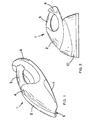
- Figure 1 is a schematic perspective view of a portable vacuum cleaner of the present invention in a vacuum cleaning mode;
- Figure 2 is a schematic side view of the portable vacuum cleaner of Figure 1 in a self-cleaning mode and mounted to a cleaning receptacle;
- Figure 3 is a perspective view from below of the vacuum cleaner of Figure 1 in which the housing is in an open condition;
- Figure 4 is a perspective view from above of the cleaning receptacle of Figure 2;
- Figure 5 is a perspective view from above and one side of the vacuum cleaner and cleaning receptacle of Figure 2;
- Figure 6 is a perspective front view of a filter assembly of the vacuum cleaner of Figure 1;
- Figure 7 is a perspective rear view of the filter assembly of Figure 6;
- Figure 8 is a sideways perspective view of a vibrator mechanism of the vacuum cleaner of Figure 1;
- Figure 9 is a rear cut-away view of a front portion of the vacuum cleaner of Figure 1 showing the filter assembly of Figure 8;
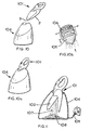
- Figure 10a is a schematic perspective view of a second embodiment of a portable vacuum cleaner and cleaning receptacle of the present invention in a vacuum cleaning mode;
- Figure 10b is a schematic perspective view of the filter system employed by the vacuum cleaner of Figure 10a;
- Figure 10c is a schematic perspective view of the vacuum cleaner loaded into the cleaning receptacle of Figure 10a;
- Figure 11 is a schematic perspective cut away view of the vacuum cleaner of Figure 10c in the self-cleaning mode;
- Figure 12 is a cross sectional view of the vacuum cleaner of Figure 10c in vacuum cleaning mode; and
- Figure 13 is a cross sectional view of the vacuum cleaner of Figure 10c loaded into the receptacle in self-cleaning mode.
-
- Referring to Figure 1, a vacuum cleaner 1 comprises a
housing 2 of durable plastics material. Thehousing 2 includes an integrally formedhandle 3 and aswitch 4 for a user to depress, the switch activating a motor (not shown) of the vacuum cleaner 1. Aninlet 5 is located at the front of thehousing 2. In operation, actuation of the motor causes a fan (not shown) to draw air throughinlet 5 and pass it through a filter assembly (not shown) such that dust particles contained in the air are removed. Cleaned air is then passed back into the atmosphere through outlet 6. The vacuumcleaner housing 2 also comprises a hingeddoor 7, the purpose of which will be described in detail below. - A cleaning
receptacle 10 is provided such that vacuum cleaner 1 can be mounted onreceptacle 10 when the vacuum cleaner 1 is not in use. When the vacuum cleaner 1 is mounted onto thereceptacle 10 as shown in Figure 2,door 7 is automatically opened on engagement with thereceptacle 10 and a vacuum cleaner recharging and cleaning process is automatically commenced. - Referring now to Figures 3 to 5, the
door 7 of vacuum cleaner 1 comprises a lever 8, and thedoor 7 is generally biased towards the closed position (as shown in Figure 1) by a spring (not shown) such as a torsion spring at the hinge between thedoor 7 and the adjacent part ofhousing 2.Door 7 can be opened however by applying a sufficient contact force to lever 8 such that thedoor 7 is pivoted into the open condition as shown in Figure 3. - Referring now to Figure 4,
receptacle 10 is provided with anengagement surface 9 which cooperates with lever 8 such that when the vacuum cleaner 1 is mounted ontoreceptacle 10, thedoor 7 is automatically opened.Receptacle 10 is provided with a set ofreceptacle doors 11 which are spring loaded towards a closed condition. In Figure 4,receptacle doors 11 are shown in a partially open condition. Accordingly, when vacuum cleaner 1 is mounted ontoreceptacle 10, the action of pushing the vacuum cleaner onto the receptacle opensreceptacle doors 11, and correspondingly opens vacuumcleaner door 7. This enables loose dirt particles insidedoor 7 to slide down the chute defined by theopen door 7 into thereceptacle 10. - The
receptacle 10 is also provided with a pair ofelectrical contacts 12 adapted to contact a further set ofelectrical contacts 13 disposed on the underside of thehousing 2 of the vacuum cleaner 1. These electrical contacts enable charging of rechargeable batteries (not shown) of the vacuum cleaner for energising the vacuum cleaner motor, and also operation of a vibrator mechanism as will be described below. - Referring now to Figures 6 and 7, a
filter assembly 20 comprises acoarse filter 21 formed from a mesh of plastics or metallic material, and afine filter 22 having a filter element formed from fibrous paper. Thefine filter 22 has a plurality ofpleats 23 which increase the working surface area of thefine filter 22, and thecoarse filter 21 andfine filter 22 are supported on aframe 24 of durable plastics material. - Referring again to Figure 3,
filter assembly 20 can be seen in position in thehousing 2 of the vacuum cleaner 1. When the vacuum cleaner 1 is activated, (it will be appreciated that when the vacuum cleaner is inoperation door 7 is in the closed position), the fan (not shown) draws air throughinlet 5 and firstly acrosscoarse filter 21, which removes particles larger than a first size, and then acrossfine filter 22 which removes particles from the air flow that are small enough to pass throughcoarse filter 21. - Referring to Figure 8, a
filter vibrator mechanism 25 comprises an electric motor 26 connected to an eccentrically mountedweight 27. When the motor 26 is operated, the eccentrically mounted weight rotates and causes the assembly to vibrate. The motor 26 is mounted on aplastic mounting portion 28 which comprises a plurality of integrally formedteeth 29 which are placed in contact with the pleats of thefine filter 22. - As shown in Figure 9, the
vibrator mechanism 25 is attached to thefine filter 22 by virtue ofteeth 29 fixedly engagingpleats 23. Consequently, it can be seen that the vibrations caused by eccentrically mountedweight 27 are imparted to the pleats offine filter 22 such that thefilter 22 is vibrated. - The operation of the filter cleaning mechanism will now be described.
- In order to recharge the vacuum cleaner batteries (not shown) and clean the
fine filter 22, the vacuum cleaner 1 is placed on the cleaning receptacle as shown in Figures 2 and 5. In this condition, the vacuumcleaner door 7 is held open andfine filter 22 is located abovecoarse filter 21. - Mounting of vacuum cleaner 1 onto
receptacle 10 causes therespective contacts vibrator mechanism 25. Any dust shaken fromfine filter 23 is able to fall back throughcoarse filter 21 and into thereceptacle 10 viaopen door 7. - The
receptacle 20 is provided with electronics which link the cleaning cycle, i.e. the length of time that thevibrator 25 is operated for, to the previous operation time of the vacuum cleaner 1. This may be accomplished by sensing the level of battery charge to determine the length of time that the vacuum cleaner has been in operation. There is no requirement for the timing electronics to be present in thereceptacle 10, as this could equally be accomplished by locating the electronics in the vacuum cleaner 1. - Referring now to Figures 10a to 13, a
vacuum cleaner 101 of a second embodiment of the present invention includes ahousing 102 having aninlet 103 for intake of air and an outlet (not shown) for expulsion of air. Thehousing portion 102 contains a generally conical coarse filter 105 (Figure 10b) for removing dust particles from air flowing from theinlet 103 to the outlet, and a pleatedfine filter 106 for removing smaller particles of dust from air flowing from the coarse filter 105 (Figure 10b) to the outlet (not shown). Thecoarse filter 105 is moveable axially relative to thehousing 102 andfine filter 106 between a working position in which thecoarse filter 105 abuts a sealing ring (Figure 12) to force air travelling from the inlet to the outlet through thefilter 105, and a cleaning position in which thefilter 105 is spaced from the sealingring 113 to enable dirt released from the fine filter to pass around the periphery of thecoarse filter 105 as shown in Figure 13. Areceptacle 104 is provided to store the vacuum cleaner in an upright position as shown in Figure 10c. - Referring now to Figure 11, the
receptacle 104 is provided such that when thevacuum cleaner 101 is loaded into the receptacle, thehousing 102 pivots open to reveal anopening 107 through whichdust particles 108 can be released into thereceptacle 104. Thereceptacle 104 is also provided with abattery charger 109 adapted to recharge the vacuum cleaner batteries (not shown). - Referring to Figures 12 and 13, the operation of the
vacuum cleaner 101 shown in Figures 10a to 11 will now be described. - Referring to Figure 12, in the vacuum cleaning mode of
vacuum cleaner 101, the fan 110 displaces air throughoutlets 111 thereby drawing air in through theinlet 103 of thehousing 102. The resultant air flow through thevacuum cleaner 101 forces thecoarse filter body 112 into contact with asealing ring 113 at the surface denoted by 114. Thecoarse filter 105 has afilter body 112, anoutlet aperture 116 to allow the escape of air entering through thecoarse filter 105, as well as avibrator 117 such as a piezoelectric transducer or an electric motor having an eccentric weight, with associatedpower supply wiring 121. Thewiring 121 supplies stepped-down mains supply. - In the vacuum cleaning mode shown in Figure 12, air entering the
inlet 103 contains dust particles. Thecoarse filter element 105 traps dust particles in the air flow larger than a first particle size. Dust particles smaller than this first particle size will pass through thecoarse filter 105, into the cup-shapedfine filter 106. Thefine filter 106 at least partially traps the smaller dust particles on itsinner surfaces 118 in the air flowing fromoutlet aperture 116 to thefan outlets 111. - Referring now to Figure 13, the
vacuum cleaner 101 is shown loaded into the cleaningreceptacle 104. The cleaningreceptacle 104 is adapted to open the housing nose portion 120 of the vacuumcleaner housing 102. In the arrangement shown in Figure 13, the suction fan 110 is deactivated, thereby allowing thecoarse filter body 112 to drop into the cleaning position under gravity. In this position, thecoarse filter body 112 is no longer in contact with the sealingring 113, creating an aperture 119 around which dirt particles freed from the fine filter can travel. - The action of loading the
vacuum cleaner 101 into the cleaningreceptacle 104 activatesvibrator 117, to cause thecoarse filter body 112 to vibrate in the axial direction shown by arrow A. In this position, dust particles trapped on thefine filter 106 are able to either fall through aperture 119 into thereceptacle 104, or into thecoarse filter body 112. The vibration ofcoarse filter body 112 will firstly release any dust particles trapped in thecoarse filter 105, and secondly release any smaller dust particles that have fallen into thefilter body 112 back through thecoarse filter 105. In this way, the vacuum cleaner is self cleaned by the combined action of gravity and the vibration of thecoarse filter body 112. - In the cleaning position of Figure 13, the vacuum cleaner batteries (not shown) are electrically connected to the
battery charger 109 of Figure 11. The same power supply is also used for providing power to thevibration units 117. It can be seen therefore that thevacuum cleaner 101 can be left in thereceptacle 104 to simultaneously self-clean and recharge. - It will be appreciated by persons skilled in the art that the above embodiments have been described by way of example only and not in any limitative sense, and that various alterations and modifications are possible without departure from the scope of the invention as defined by the appended claims. In particular, in the second embodiment described above and shown in Figures 12 and 13, the cup-shaped
filter element 106 is fixed relative to thehousing 102 by virtue of being mounted on thesealing ring 113. The cup-shapedfine filter element 106 may be mounted on thecoarse filter body 112 such that thefine filter element 106 is also subject to vibration when thevacuum cleaner 101 is in the self-cleaning mode. Also, in the embodiments described, instead of, or in addition to, including a vibrator in the form of an eccentrically mounted weight, the vibrator could also comprise a piezoelectric transducer, a loudspeaker or other means suitable for vibrating the filters.
Claims (30)
- A vacuum cleaner comprising:-wherein the vacuum cleaner has a working condition, in which said suction means causes air to flow from at least one said inlet to at least one said outlet, and a self-cleaning condition in which the vibrator means causes vibrations of said first and/or second said filter means.a housing having at least one inlet for allowing intake of air and at least one outlet for allowing escape of air;suction means arranged in the housing for causing air to flow from at least one said inlet to at least one said outlet;first filter means for preventing passage of particles larger than a first predetermined particle size in air flowing from at least one inlet to at least one outlet;second filter means for preventing passage of particles larger than a second predetermined size, smaller than said first predetermined size, in air flowing from said first filter means to at least one said outlet; andelectrically operated vibrator means for causing vibrations of said first filter means and/or said second filter means;
- A vacuum cleaner according to claim 1, wherein said second filter means comprises at least one pleated filter element.
- A vacuum cleaner according to claim 2, wherein said vibrator means includes a plurality of projections adapted to fit between pleats of at least one said filter element.
- A vacuum cleaner according to any one of the preceding claims, wherein said housing is adapted to open when mounted to a cleaning receptacle for supporting said vacuum cleaner in said self-cleaning condition.
- A vacuum cleaner according to claim 4, further comprising engaging means adapted to open said housing when engaged by a cleaning receptacle.
- A vacuum cleaner according to claim 4 or 5, wherein said housing comprises at least one closure member adapted to pivot outwards of said housing to form a respective chute.
- A vacuum cleaner according to claim 6, further comprising locking means for releasably locking the or each said closure member in a closed condition.
- A vacuum cleaner according to any one of the preceding claims, wherein the housing defines a hollow handle, and air flows through the handle in use in the working condition from at least one said inlet to at least one said outlet.
- A vacuum cleaner according to any one of the preceding claims, wherein the suction means is adapted to cause air to flow from at least one said outlet to at least one said inlet in said self-cleaning condition.
- A vacuum cleaner according to any one of the preceding claims, wherein said first filter means has at least one first filter body having a respective working condition, in which said body sealingly engages said housing such that air travelling from the or each said inlet to the or each said outlet is forced through said first filter means, and a respective self-cleaning condition in which said body allows at least some particles retained by said second filter means to pass said first filter means.
- A vacuum cleaner according to claim 10, wherein said suction means in use urges at least one said first filter body into a respective working condition thereof.
- A vacuum cleaner according to claim 10 or 11, wherein at least one said first filter body is adapted to move from the respective working condition thereof to the self-cleaning condition thereof under gravity.
- A vacuum cleaner according to any one of claims 10 to 12, wherein said vibrator means is adapted to cause vibration of at least one said first filter body in a direction substantially parallel to the direction of movement of said filter body from the working to the self-cleaning condition thereof.
- A vacuum cleaner according to any one of the preceding claims, wherein said vibrator means includes at least one electric motor adapted to drive at least one eccentrically arranged weight.
- A vacuum cleaner according to any one of the preceding claims, wherein said vibrator means includes at least one piezoelectric transducer.
- A vacuum cleaner according to any one of the preceding claims, wherein said vibrator means includes a loudspeaker.
- A vacuum cleaner according to claim 16, wherein at least one said loudspeaker is tuned to cause resonant vibration in said second filter means.
- A vacuum cleaner according to any one of the preceding claims, wherein said vibrator means is adapted to derive electrical power from stepped-down mains supply.
- A vacuum cleaner substantially as hereinbefore described with reference to the accompanying drawings.
- A cleaning receptacle for a vacuum cleaner, the receptacle comprising:-support means for supporting said vacuum cleaner; andelectrical connector means for supplying electrical power to said vibrator means.
- A receptacle according to claim 22, wherein said support means is adapted to support said vacuum cleaner such that said second filter means is located substantially above said first filter means.
- A receptacle according to claim 20 or 21, further comprising a dust collection portion.
- A receptacle according to any one of claims 20 to 22, further comprising at least one closure member, and biasing means for biasing the or each said closure member towards a closed position.
- A receptacle according to any one of claims 20 to 23, further comprising transformer means for stepping down mains voltage.
- A receptacle according to any one of claims 20 to 24, further comprising engagement means for engaging said vacuum cleaner to open said housing thereof.
- A receptacle according to any one of claims 20 to 25, further comprising battery charger means for recharging at least one battery of said vacuum cleaner.
- A receptacle according to any one of claims 20 to 26, wherein one of the vacuum cleaner or the receptacle further comprises a timer such that said vibrator means is activated for a predetermined time when said vacuum cleaner is mounted to said receptacle.
- A receptacle according to claims 26 and 27, wherein said timer is adapted to be actuated for a time determined by the charge level of at least one battery of the vacuum cleaner.
- A cleaning receptacle for a vacuum cleaner, the receptacle substantially as hereinbefore described with reference to the accompanying drawings.
- A vacuum cleaner assembly comprising a vacuum cleaner according to any one of claims 1 to 19 and a receptacle according to any one of claims 20 to 29.
Applications Claiming Priority (2)
| Application Number | Priority Date | Filing Date | Title |
|---|---|---|---|
| GB0318284 | 2003-08-05 | ||
| GBGB0318284.7A GB0318284D0 (en) | 2003-08-05 | 2003-08-05 | Hand-held vacuum cleaner |
Publications (3)
| Publication Number | Publication Date |
|---|---|
| EP1504710A2 true EP1504710A2 (en) | 2005-02-09 |
| EP1504710A3 EP1504710A3 (en) | 2006-03-22 |
| EP1504710B1 EP1504710B1 (en) | 2010-09-08 |
Family
ID=27839637
Family Applications (1)
| Application Number | Title | Priority Date | Filing Date |
|---|---|---|---|
| EP04017711A Expired - Lifetime EP1504710B1 (en) | 2003-08-05 | 2004-07-27 | Self-cleaning vacuum cleaner and receptacle therefor |
Country Status (5)
| Country | Link |
|---|---|
| US (1) | US7386916B2 (en) |
| EP (1) | EP1504710B1 (en) |
| AT (1) | ATE480176T1 (en) |
| DE (1) | DE602004028995D1 (en) |
| GB (1) | GB0318284D0 (en) |
Cited By (6)
| Publication number | Priority date | Publication date | Assignee | Title |
|---|---|---|---|---|
| EP2085012A1 (en) * | 2008-01-31 | 2009-08-05 | BLACK & DECKER INC. | Vacuum filter cleaning device |
| US7673369B2 (en) | 2005-07-22 | 2010-03-09 | Panasonic Corporation Of North America | Floor cleaning apparatus with filter cleaning system |
| US7752708B2 (en) | 2006-03-08 | 2010-07-13 | Panasonic Corporation Of North America | Floor cleaning apparatus with filter cleaning system |
| WO2015070322A1 (en) | 2013-11-18 | 2015-05-21 | Canplas Industries Ltd. | Handheld vacuum cleaner and docking assembly for connecting to a central vacuum system |
| EP2529653A3 (en) * | 2011-01-19 | 2018-01-03 | Hoover Limited | Hand-held vacuum cleaner |
| EP2698091A3 (en) * | 2012-08-16 | 2018-03-14 | Miele & Cie. KG | Fine dust collecting body for a vacuum cleaner, and vacuum cleaner comprising such a fine dust collecting body, and method for operating such a vacuum cleaner |
Families Citing this family (93)
| Publication number | Priority date | Publication date | Assignee | Title |
|---|---|---|---|---|
| SE0300355D0 (en) * | 2003-02-10 | 2003-02-10 | Electrolux Ab | Hand held vacuum cleaner |
| SE0600668L (en) * | 2006-03-24 | 2007-10-23 | Electrolux Abp | Handheld vacuum cleaner |
| SE531125C2 (en) * | 2007-01-19 | 2008-12-23 | Electrolux Ab | Improvements in air flow losses in a vacuum cleaner |
| US8424154B2 (en) | 2006-04-10 | 2013-04-23 | Ab Electrolux | Vacuum cleaner with filter cleaning means |
| US20080040883A1 (en) * | 2006-04-10 | 2008-02-21 | Jonas Beskow | Air Flow Losses in a Vacuum Cleaners |
| CN101460083B (en) * | 2006-04-10 | 2014-08-13 | 伊莱克斯公司 | Vacuum cleaner |
| US20070292749A1 (en) * | 2006-06-15 | 2007-12-20 | Richard Coombs | Battery assembly for vacuums |
| US20080010775A1 (en) * | 2006-07-17 | 2008-01-17 | Sweepster Attachments, Llc | Rotary broom with vacuum dust control |
| JP2010512195A (en) | 2006-12-12 | 2010-04-22 | ジービーディー コーポレーション | Switchable surface cleaning device |
| CA2599303A1 (en) * | 2007-08-29 | 2009-02-28 | Gbd Corp. | Surface cleaning apparatus |
| US10765277B2 (en) | 2006-12-12 | 2020-09-08 | Omachron Intellectual Property Inc. | Configuration of a surface cleaning apparatus |
| US12220099B2 (en) | 2006-12-12 | 2025-02-11 | Omachron Intellectual Property Inc. | Surface cleaning apparatus |
| US8950039B2 (en) | 2009-03-11 | 2015-02-10 | G.B.D. Corp. | Configuration of a surface cleaning apparatus |
| US20080175761A1 (en) * | 2007-01-19 | 2008-07-24 | Guardian Technologies Llc | Air Sanitizing and Charging/Recharging Base and Rechargeable Device Arrangement |
| US8402601B2 (en) * | 2007-01-23 | 2013-03-26 | AB Electronlux | Vacuum cleaner nozzle |
| US8015657B2 (en) * | 2007-02-09 | 2011-09-13 | Black & Decker Inc. | Vacuum electronic power tool sense |
| DE602007010720D1 (en) * | 2007-02-12 | 2011-01-05 | Black & Decker Inc | vacuum cleaner |
| US11751733B2 (en) | 2007-08-29 | 2023-09-12 | Omachron Intellectual Property Inc. | Portable surface cleaning apparatus |
| US12048409B2 (en) | 2007-03-11 | 2024-07-30 | Omachron Intellectual Property Inc. | Portable surface cleaning apparatus |
| US20100175217A1 (en) * | 2007-08-29 | 2010-07-15 | G.B.D. Corp. | Cyclonic surface cleaning apparatus with externally positioned dirt chamber |
| US12004700B2 (en) | 2007-08-29 | 2024-06-11 | Omachron Intellectual Property Inc. | Cyclonic surface cleaning apparatus |
| US7962994B2 (en) * | 2007-10-11 | 2011-06-21 | Black & Decker Inc. | Vacuum electronic switch detection system |
| US8516650B2 (en) * | 2007-10-11 | 2013-08-27 | Black & Decker Inc. | Vacuum electronic water sense circuit |
| US7644469B2 (en) * | 2007-10-11 | 2010-01-12 | Black & Decker Inc. | Vacuum electronics isolation method |
| EP3010071B1 (en) * | 2008-03-14 | 2018-08-29 | Royal Appliance Mfg. Co. | Removable battery pack with latching mechanism |
| USD652377S1 (en) | 2008-10-16 | 2012-01-17 | Techtronic Floor Care Technology Limited | Battery charger combination |
| BRPI0919686A2 (en) | 2008-10-22 | 2021-04-20 | Rosemount Inc | Plug-and-play sensor/transmitter for process instrumentation |
| US9591952B2 (en) | 2009-03-11 | 2017-03-14 | Omachron Intellectual Property Inc. | Hand vacuum cleaner with removable dirt chamber |
| US9480373B2 (en) | 2009-03-13 | 2016-11-01 | Omachron Intellectual Property Inc. | Surface cleaning apparatus |
| US11612288B2 (en) | 2009-03-13 | 2023-03-28 | Omachron Intellectual Property Inc. | Surface cleaning apparatus |
| US9226633B2 (en) | 2009-03-13 | 2016-01-05 | Omachron Intellectual Property Inc. | Surface cleaning apparatus |
| CA2674761C (en) | 2009-03-13 | 2016-10-04 | G.B.D. Corp. | Surface cleaning apparatus with different cleaning configurations |
| US9392916B2 (en) | 2009-03-13 | 2016-07-19 | Omachron Intellectual Property Inc. | Surface cleaning apparatus |
| US11690489B2 (en) | 2009-03-13 | 2023-07-04 | Omachron Intellectual Property Inc. | Surface cleaning apparatus with an external dirt chamber |
| CA2917900C (en) | 2009-03-13 | 2019-01-08 | Omachron Intellectual Property Inc. | Portable surface cleaning apparatus |
| CA2674376A1 (en) | 2009-03-13 | 2010-09-13 | G.B.D. Corp. | Surface cleaning apparatus with different cleaning configurations |
| US9198551B2 (en) | 2013-02-28 | 2015-12-01 | Omachron Intellectual Property Inc. | Surface cleaning apparatus |
| US9138114B2 (en) | 2009-03-13 | 2015-09-22 | Omachron Intellectual Property Inc. | Surface cleaning apparatus |
| US9211044B2 (en) | 2011-03-04 | 2015-12-15 | Omachron Intellectual Property Inc. | Compact surface cleaning apparatus |
| US9427122B2 (en) | 2009-03-13 | 2016-08-30 | Omachron Intellectual Property Inc. | Surface cleaning apparatus |
| US9591953B2 (en) | 2009-03-13 | 2017-03-14 | Omachron Intellectual Property Inc. | Surface cleaning apparatus |
| US8875340B2 (en) | 2010-03-12 | 2014-11-04 | G.B.D. Corp. | Surface cleaning apparatus with enhanced operability |
| US9038236B2 (en) | 2012-04-25 | 2015-05-26 | Shop Vac Corporation | Filter shaker |
| US9314138B2 (en) | 2013-02-28 | 2016-04-19 | Omachron Intellectual Property Inc. | Surface cleaning apparatus |
| US9227151B2 (en) | 2013-02-28 | 2016-01-05 | Omachron Intellectual Property Inc. | Cyclone such as for use in a surface cleaning apparatus |
| US9364127B2 (en) | 2013-02-28 | 2016-06-14 | Omachron Intellectual Property Inc. | Surface cleaning apparatus |
| US9295995B2 (en) | 2013-02-28 | 2016-03-29 | Omachron Intellectual Property Inc. | Cyclone such as for use in a surface cleaning apparatus |
| US9451855B2 (en) | 2013-02-28 | 2016-09-27 | Omachron Intellectual Property Inc. | Surface cleaning apparatus |
| US9326652B2 (en) | 2013-02-28 | 2016-05-03 | Omachron Intellectual Property Inc. | Surface cleaning apparatus |
| US9238235B2 (en) | 2013-02-28 | 2016-01-19 | Omachron Intellectual Property Inc. | Cyclone such as for use in a surface cleaning apparatus |
| US9820621B2 (en) | 2013-02-28 | 2017-11-21 | Omachron Intellectual Property Inc. | Surface cleaning apparatus |
| US9456721B2 (en) | 2013-02-28 | 2016-10-04 | Omachron Intellectual Property Inc. | Surface cleaning apparatus |
| US9215960B2 (en) | 2013-02-28 | 2015-12-22 | Omachron Intellectual Property Inc. | Surface cleaning apparatus |
| US20140237764A1 (en) | 2013-02-28 | 2014-08-28 | G.B.D. Corp. | Cyclone such as for use in a surface cleaning apparatus |
| US9227201B2 (en) | 2013-02-28 | 2016-01-05 | Omachron Intellectual Property Inc. | Cyclone such as for use in a surface cleaning apparatus |
| US11950745B2 (en) * | 2014-12-17 | 2024-04-09 | Omachron Intellectual Property Inc. | Surface cleaning apparatus |
| US10159925B2 (en) * | 2016-01-12 | 2018-12-25 | Aurabeat Holdings Limited | Acoustic aided air filter and a method of air filtration thereof |
| CN109475802B (en) | 2016-04-15 | 2022-07-19 | 创科无线普通合伙 | Hand-held vacuum cleaner |
| US11478117B2 (en) | 2016-08-29 | 2022-10-25 | Omachron Intellectual Property Inc. | Surface cleaning apparatus |
| US9962050B2 (en) | 2016-08-29 | 2018-05-08 | Omachron Intellectual Property Inc. | Surface cleaning apparatus |
| US10441124B2 (en) | 2016-08-29 | 2019-10-15 | Omachron Intellectual Property Inc. | Surface cleaning apparatus |
| US10413141B2 (en) | 2016-08-29 | 2019-09-17 | Omachron Intellectual Property Inc. | Surface cleaning apparatus |
| US10136779B2 (en) | 2016-08-29 | 2018-11-27 | Omachron Intellectual Property Inc. | Surface cleaning apparatus |
| US10433689B2 (en) | 2016-08-29 | 2019-10-08 | Omachron Intellectual Property Inc. | Surface cleaning apparatus |
| US10321794B2 (en) | 2016-08-29 | 2019-06-18 | Omachron Intellectual Property Inc. | Surface cleaning apparatus |
| US10441125B2 (en) | 2016-08-29 | 2019-10-15 | Omachron Intellectual Property Inc. | Surface cleaning apparatus |
| US10729295B2 (en) | 2016-08-29 | 2020-08-04 | Omachron Intellectual Property Inc. | Surface cleaning apparatus |
| US10136780B2 (en) | 2016-08-29 | 2018-11-27 | Omachron Intellectual Property Inc. | Surface cleaning apparatus |
| US10405711B2 (en) | 2016-08-29 | 2019-09-10 | Omachron Intellectual Property Inc. | Surface cleaning apparatus |
| US10292550B2 (en) | 2016-08-29 | 2019-05-21 | Omachron Intellectual Property Inc. | Surface cleaning apparatus |
| AU201712063S (en) | 2016-10-14 | 2017-04-26 | Tti Macao Commercial Offshore Ltd | Handheld vacuum cleaner |
| AU201712064S (en) | 2016-10-14 | 2017-04-27 | Tti Macao Commercial Offshore Ltd | Handheld vacuum cleaner |
| US11285495B2 (en) | 2016-12-27 | 2022-03-29 | Omachron Intellectual Property Inc. | Multistage cyclone and surface cleaning apparatus having same |
| US10464746B2 (en) * | 2016-12-28 | 2019-11-05 | Omachron Intellectual Property Inc. | Dust and allergen control for surface cleaning apparatus |
| US10244909B2 (en) * | 2016-12-28 | 2019-04-02 | Omachron Intellectual Property Inc. | Dust and allergen control for surface cleaning apparatus |
| US11794141B2 (en) | 2021-01-25 | 2023-10-24 | Omachron Intellectual Property Inc. | Multiuse home station |
| DE102017127131A1 (en) * | 2017-11-17 | 2019-05-23 | Vorwerk & Co. Interholding Gmbh | Regenerative vacuum cleaner |
| AU201812645S (en) | 2017-12-05 | 2018-07-31 | Tti Macao Commercial Offshore Ltd | Housing for a vacuum filter |
| CN108903806B (en) * | 2018-08-17 | 2023-08-22 | 莱克电气股份有限公司 | A fast switching structure of air duct for Hypa self-cleaning vacuum cleaner |
| CN108903805B (en) * | 2018-08-17 | 2023-07-04 | 莱克电气股份有限公司 | Motor base for self-cleaning type HEPA dust collector |
| CN108937723B (en) * | 2018-08-17 | 2023-07-04 | 莱克电气股份有限公司 | A fast switching device for air duct used in Hypa self-cleaning vacuum cleaner |
| CN217096845U (en) | 2018-08-31 | 2022-08-02 | 米沃奇电动工具公司 | Electric tool |
| CN114557630B (en) | 2018-10-22 | 2023-12-29 | 奥马克罗知识产权有限公司 | air handling unit |
| DE212019000449U1 (en) * | 2018-12-13 | 2021-07-21 | Koki Holdings Co., Ltd. | cleanser |
| WO2020224601A1 (en) * | 2019-05-07 | 2020-11-12 | 江苏美的清洁电器股份有限公司 | Dust deposition base and cleaning apparatus assembly having same |
| JP2020202892A (en) * | 2019-06-14 | 2020-12-24 | 日本電産株式会社 | Dust collector, cleaner, and self-propelled cleaner |
| JP2020202893A (en) * | 2019-06-14 | 2020-12-24 | 日本電産株式会社 | Dust collection device, cleaner, and self-propelled cleaner |
| US11583156B2 (en) | 2019-08-14 | 2023-02-21 | Samsung Electronics Co., Ltd. | Stand for cleaner and cleaning apparatus having the same |
| CN114617466B (en) * | 2020-12-11 | 2023-06-16 | 美智纵横科技有限责任公司 | Self-cleaning method and device of dust collector and dust collector |
| CN114079295A (en) * | 2021-03-04 | 2022-02-22 | 浙江绍兴苏泊尔生活电器有限公司 | Power supply control method and device, cleaning base station, storage medium and product program |
| CN113786138A (en) * | 2021-09-22 | 2021-12-14 | 北京顺造科技有限公司 | Surface cleaning system and self-cleaning method for surface cleaning equipment |
| EP4559367B1 (en) | 2022-07-07 | 2026-04-22 | BISSELL Inc. | Modular head system for handheld extraction cleaner, dry vacuum accessory for handheld extraction cleaner, and handheld extraction cleaner |
| US20240382056A1 (en) * | 2023-05-16 | 2024-11-21 | Omachron Intellectual Property Inc. | Air treatment unit |
Citations (6)
| Publication number | Priority date | Publication date | Assignee | Title |
|---|---|---|---|---|
| US4787923A (en) | 1986-08-27 | 1988-11-29 | Tennant Company | Apparatus for cleaning an air filter |
| US5560076A (en) | 1994-11-14 | 1996-10-01 | Hoovine Industrial Limited | Combined vacuum cleaner and torch |
| WO1997020492A1 (en) | 1995-12-04 | 1997-06-12 | Emaco Limited | A cleaner |
| GB2311462A (en) | 1996-03-28 | 1997-10-01 | Black & Decker Inc | Blower vacuum |
| EP0860554A2 (en) | 1997-02-19 | 1998-08-26 | Tennant Company | Sweeper with electromagnetic filter cleaning |
| EP1070478A2 (en) | 1999-07-17 | 2001-01-24 | Black & Decker Inc. | Vacuum cleaner |
Family Cites Families (15)
| Publication number | Priority date | Publication date | Assignee | Title |
|---|---|---|---|---|
| US3591888A (en) * | 1969-12-22 | 1971-07-13 | Matsushita Electric Industrial Co Ltd | Electrically operated vacuum cleaner equipped with automatic filter-cleaning means |
| US3731465A (en) * | 1970-01-19 | 1973-05-08 | Hitachi Ltd | Electric vacuum cleaner |
| US3708962A (en) * | 1970-03-20 | 1973-01-09 | Sanyo Electric Co | Vacuum cleaner |
| US3856488A (en) * | 1972-09-05 | 1974-12-24 | Mitsubishi Electric Corp | Electric vacuum cleaner |
| EP0024636B2 (en) * | 1979-08-16 | 1989-10-18 | Hitachi, Ltd. | Vacuum cleaner |
| US4328014A (en) * | 1981-04-22 | 1982-05-04 | The Scott & Fetzer Company | Sweeper hopper with filter assembly |
| JPS6181567A (en) * | 1984-09-13 | 1986-04-25 | Honda Motor Co Ltd | Exhaust recirculation control method for internal combustion engine |
| JPH0747009B2 (en) * | 1985-08-08 | 1995-05-24 | 三洋電機株式会社 | Small portable vacuum cleaner |
| US4718140A (en) * | 1986-03-10 | 1988-01-12 | Henry Johnson | Fireplace blower and vacuum |
| DE3926777A1 (en) * | 1989-08-14 | 1991-02-21 | Vorwerk Co Interholding | ELECTRICALLY OPERATED HAND SUCTION UNIT |
| JPH05192278A (en) * | 1992-01-20 | 1993-08-03 | Matsushita Electric Ind Co Ltd | Vacuum cleaner |
| JPH0994189A (en) * | 1995-09-29 | 1997-04-08 | Nissei Giken:Kk | Electric vacuum cleaner |
| JP2000254054A (en) * | 1999-03-05 | 2000-09-19 | Mitsumasa Sakamoto | Dust removal device of small dust-collector utilizing vibration of speaker |
| JP3674031B2 (en) * | 2001-06-19 | 2005-07-20 | ツインバード工業株式会社 | Vacuum cleaner |
| JP3749173B2 (en) * | 2001-12-28 | 2006-02-22 | 三洋電機株式会社 | Dust collector for vacuum cleaner and electric vacuum cleaner |
-
2003
- 2003-08-05 GB GBGB0318284.7A patent/GB0318284D0/en not_active Ceased
-
2004
- 2004-07-27 AT AT04017711T patent/ATE480176T1/en not_active IP Right Cessation
- 2004-07-27 DE DE602004028995T patent/DE602004028995D1/en not_active Expired - Lifetime
- 2004-07-27 EP EP04017711A patent/EP1504710B1/en not_active Expired - Lifetime
- 2004-08-05 US US10/912,374 patent/US7386916B2/en not_active Expired - Fee Related
Patent Citations (6)
| Publication number | Priority date | Publication date | Assignee | Title |
|---|---|---|---|---|
| US4787923A (en) | 1986-08-27 | 1988-11-29 | Tennant Company | Apparatus for cleaning an air filter |
| US5560076A (en) | 1994-11-14 | 1996-10-01 | Hoovine Industrial Limited | Combined vacuum cleaner and torch |
| WO1997020492A1 (en) | 1995-12-04 | 1997-06-12 | Emaco Limited | A cleaner |
| GB2311462A (en) | 1996-03-28 | 1997-10-01 | Black & Decker Inc | Blower vacuum |
| EP0860554A2 (en) | 1997-02-19 | 1998-08-26 | Tennant Company | Sweeper with electromagnetic filter cleaning |
| EP1070478A2 (en) | 1999-07-17 | 2001-01-24 | Black & Decker Inc. | Vacuum cleaner |
Cited By (11)
| Publication number | Priority date | Publication date | Assignee | Title |
|---|---|---|---|---|
| US7673369B2 (en) | 2005-07-22 | 2010-03-09 | Panasonic Corporation Of North America | Floor cleaning apparatus with filter cleaning system |
| GB2428559B (en) * | 2005-07-22 | 2010-05-19 | Panasonic Corp North America | Floor cleaning apparatus with filter cleaning system |
| US7752708B2 (en) | 2006-03-08 | 2010-07-13 | Panasonic Corporation Of North America | Floor cleaning apparatus with filter cleaning system |
| US7908707B2 (en) | 2006-03-08 | 2011-03-22 | Panasonic Corporation Of North America | Floor cleaning apparatus with filter cleaning system |
| EP2085012A1 (en) * | 2008-01-31 | 2009-08-05 | BLACK & DECKER INC. | Vacuum filter cleaning device |
| US8327487B2 (en) | 2008-01-31 | 2012-12-11 | Black & Decker Inc. | Vacuum filter cleaning device |
| EP2529653A3 (en) * | 2011-01-19 | 2018-01-03 | Hoover Limited | Hand-held vacuum cleaner |
| EP2698091A3 (en) * | 2012-08-16 | 2018-03-14 | Miele & Cie. KG | Fine dust collecting body for a vacuum cleaner, and vacuum cleaner comprising such a fine dust collecting body, and method for operating such a vacuum cleaner |
| WO2015070322A1 (en) | 2013-11-18 | 2015-05-21 | Canplas Industries Ltd. | Handheld vacuum cleaner and docking assembly for connecting to a central vacuum system |
| EP3071083A4 (en) * | 2013-11-18 | 2017-07-26 | Canplas Industries Ltd. | Handheld vacuum cleaner and docking assembly for connecting to a central vacuum system |
| US9808135B2 (en) | 2013-11-18 | 2017-11-07 | Canplas Industries Ltd. | Handheld vacuum cleaner and docking assembly for connecting to a central vacuum system |
Also Published As
| Publication number | Publication date |
|---|---|
| GB0318284D0 (en) | 2003-09-10 |
| ATE480176T1 (en) | 2010-09-15 |
| DE602004028995D1 (en) | 2010-10-21 |
| EP1504710B1 (en) | 2010-09-08 |
| US7386916B2 (en) | 2008-06-17 |
| EP1504710A3 (en) | 2006-03-22 |
| US20050091784A1 (en) | 2005-05-05 |
Similar Documents
| Publication | Publication Date | Title |
|---|---|---|
| US7386916B2 (en) | Self-cleaning vacuum cleaner and receptacle therefor | |
| US7412749B2 (en) | Vacuum cleaner and floor dustpan system | |
| US8308831B2 (en) | Filter cleaning mechanisms | |
| EP1813180B1 (en) | Vacuum cleaner filter cleaning mechanisms | |
| US6434785B1 (en) | Dual filter wet/dry hand-held vacuum cleaner | |
| JP3530436B2 (en) | Vacuum cleaner dust collector and upright type vacuum cleaner | |
| CN102014720B (en) | Electric cleaner | |
| CN101721176B (en) | Dust collecting device and electric dust collector | |
| US20210345845A1 (en) | Vacuum cleaner and dust plume reduction apparatus | |
| KR100729716B1 (en) | Vacuum cleaner | |
| KR100764587B1 (en) | Vacuum cleaner having a separator for separating dust by virtue of inertial force | |
| CN117729870A (en) | Dust collector station | |
| JP3831708B2 (en) | Vacuum cleaner | |
| US7272871B1 (en) | Dirt vessel equipped with cleaning plunger | |
| CN110049704A (en) | Electric dust collector | |
| KR20220046312A (en) | Cleaner station, cleaner system including same, and residual dust removal method using the cleaner system | |
| CN214682286U (en) | Diversified electrostatic precipitator device that shakes | |
| RU2433778C1 (en) | Dust-collecting device and electric vacuum cleaner | |
| JP2004283345A (en) | Electric vacuum cleaner | |
| JP7080386B1 (en) | Garbage collection device | |
| JPH07111962A (en) | Vacuum cleaner | |
| JPS5817621Y2 (en) | dust collector |
Legal Events
| Date | Code | Title | Description |
|---|---|---|---|
| PUAI | Public reference made under article 153(3) epc to a published international application that has entered the european phase |
Free format text: ORIGINAL CODE: 0009012 |
|
| AK | Designated contracting states |
Kind code of ref document: A2 Designated state(s): AT BE BG CH CY CZ DE DK EE ES FI FR GB GR HU IE IT LI LU MC NL PL PT RO SE SI SK TR |
|
| AX | Request for extension of the european patent |
Extension state: AL HR LT LV MK |
|
| PUAL | Search report despatched |
Free format text: ORIGINAL CODE: 0009013 |
|
| AK | Designated contracting states |
Kind code of ref document: A3 Designated state(s): AT BE BG CH CY CZ DE DK EE ES FI FR GB GR HU IE IT LI LU MC NL PL PT RO SE SI SK TR |
|
| AX | Request for extension of the european patent |
Extension state: AL HR LT LV MK |
|
| RIC1 | Information provided on ipc code assigned before grant |
Ipc: A47L 9/20 20060101AFI20041021BHEP Ipc: A47L 5/24 20060101ALI20060131BHEP Ipc: A47L 9/10 20060101ALI20060131BHEP |
|
| 17P | Request for examination filed |
Effective date: 20060411 |
|
| AKX | Designation fees paid |
Designated state(s): AT BE BG CH CY CZ DE DK EE ES FI FR GB GR HU IE IT LI LU MC NL PL PT RO SE SI SK TR |
|
| 17Q | First examination report despatched |
Effective date: 20071019 |
|
| GRAP | Despatch of communication of intention to grant a patent |
Free format text: ORIGINAL CODE: EPIDOSNIGR1 |
|
| GRAS | Grant fee paid |
Free format text: ORIGINAL CODE: EPIDOSNIGR3 |
|
| GRAA | (expected) grant |
Free format text: ORIGINAL CODE: 0009210 |
|
| AK | Designated contracting states |
Kind code of ref document: B1 Designated state(s): AT BE BG CH CY CZ DE DK EE ES FI FR GB GR HU IE IT LI LU MC NL PL PT RO SE SI SK TR |
|
| REG | Reference to a national code |
Ref country code: GB Ref legal event code: FG4D |
|
| REG | Reference to a national code |
Ref country code: CH Ref legal event code: EP |
|
| REG | Reference to a national code |
Ref country code: NL Ref legal event code: T3 |
|
| REG | Reference to a national code |
Ref country code: IE Ref legal event code: FG4D |
|
| REF | Corresponds to: |
Ref document number: 602004028995 Country of ref document: DE Date of ref document: 20101021 Kind code of ref document: P |
|
| PG25 | Lapsed in a contracting state [announced via postgrant information from national office to epo] |
Ref country code: FI Free format text: LAPSE BECAUSE OF FAILURE TO SUBMIT A TRANSLATION OF THE DESCRIPTION OR TO PAY THE FEE WITHIN THE PRESCRIBED TIME-LIMIT Effective date: 20100908 Ref country code: AT Free format text: LAPSE BECAUSE OF FAILURE TO SUBMIT A TRANSLATION OF THE DESCRIPTION OR TO PAY THE FEE WITHIN THE PRESCRIBED TIME-LIMIT Effective date: 20100908 |
|
| PG25 | Lapsed in a contracting state [announced via postgrant information from national office to epo] |
Ref country code: PL Free format text: LAPSE BECAUSE OF FAILURE TO SUBMIT A TRANSLATION OF THE DESCRIPTION OR TO PAY THE FEE WITHIN THE PRESCRIBED TIME-LIMIT Effective date: 20100908 Ref country code: CY Free format text: LAPSE BECAUSE OF FAILURE TO SUBMIT A TRANSLATION OF THE DESCRIPTION OR TO PAY THE FEE WITHIN THE PRESCRIBED TIME-LIMIT Effective date: 20100908 Ref country code: SI Free format text: LAPSE BECAUSE OF FAILURE TO SUBMIT A TRANSLATION OF THE DESCRIPTION OR TO PAY THE FEE WITHIN THE PRESCRIBED TIME-LIMIT Effective date: 20100908 |
|
| PG25 | Lapsed in a contracting state [announced via postgrant information from national office to epo] |
Ref country code: SE Free format text: LAPSE BECAUSE OF FAILURE TO SUBMIT A TRANSLATION OF THE DESCRIPTION OR TO PAY THE FEE WITHIN THE PRESCRIBED TIME-LIMIT Effective date: 20100908 Ref country code: GR Free format text: LAPSE BECAUSE OF FAILURE TO SUBMIT A TRANSLATION OF THE DESCRIPTION OR TO PAY THE FEE WITHIN THE PRESCRIBED TIME-LIMIT Effective date: 20101209 |
|
| PG25 | Lapsed in a contracting state [announced via postgrant information from national office to epo] |
Ref country code: CZ Free format text: LAPSE BECAUSE OF FAILURE TO SUBMIT A TRANSLATION OF THE DESCRIPTION OR TO PAY THE FEE WITHIN THE PRESCRIBED TIME-LIMIT Effective date: 20100908 Ref country code: SK Free format text: LAPSE BECAUSE OF FAILURE TO SUBMIT A TRANSLATION OF THE DESCRIPTION OR TO PAY THE FEE WITHIN THE PRESCRIBED TIME-LIMIT Effective date: 20100908 Ref country code: RO Free format text: LAPSE BECAUSE OF FAILURE TO SUBMIT A TRANSLATION OF THE DESCRIPTION OR TO PAY THE FEE WITHIN THE PRESCRIBED TIME-LIMIT Effective date: 20100908 Ref country code: PT Free format text: LAPSE BECAUSE OF FAILURE TO SUBMIT A TRANSLATION OF THE DESCRIPTION OR TO PAY THE FEE WITHIN THE PRESCRIBED TIME-LIMIT Effective date: 20110110 Ref country code: EE Free format text: LAPSE BECAUSE OF FAILURE TO SUBMIT A TRANSLATION OF THE DESCRIPTION OR TO PAY THE FEE WITHIN THE PRESCRIBED TIME-LIMIT Effective date: 20100908 |
|
| PG25 | Lapsed in a contracting state [announced via postgrant information from national office to epo] |
Ref country code: ES Free format text: LAPSE BECAUSE OF FAILURE TO SUBMIT A TRANSLATION OF THE DESCRIPTION OR TO PAY THE FEE WITHIN THE PRESCRIBED TIME-LIMIT Effective date: 20101219 Ref country code: BE Free format text: LAPSE BECAUSE OF FAILURE TO SUBMIT A TRANSLATION OF THE DESCRIPTION OR TO PAY THE FEE WITHIN THE PRESCRIBED TIME-LIMIT Effective date: 20100908 |
|
| PLBE | No opposition filed within time limit |
Free format text: ORIGINAL CODE: 0009261 |
|
| STAA | Information on the status of an ep patent application or granted ep patent |
Free format text: STATUS: NO OPPOSITION FILED WITHIN TIME LIMIT |
|
| 26N | No opposition filed |
Effective date: 20110609 |
|
| PG25 | Lapsed in a contracting state [announced via postgrant information from national office to epo] |
Ref country code: DK Free format text: LAPSE BECAUSE OF FAILURE TO SUBMIT A TRANSLATION OF THE DESCRIPTION OR TO PAY THE FEE WITHIN THE PRESCRIBED TIME-LIMIT Effective date: 20100908 |
|
| REG | Reference to a national code |
Ref country code: DE Ref legal event code: R097 Ref document number: 602004028995 Country of ref document: DE Effective date: 20110609 |
|
| PG25 | Lapsed in a contracting state [announced via postgrant information from national office to epo] |
Ref country code: MC Free format text: LAPSE BECAUSE OF NON-PAYMENT OF DUE FEES Effective date: 20110731 |
|
| REG | Reference to a national code |
Ref country code: CH Ref legal event code: PL |
|
| REG | Reference to a national code |
Ref country code: IE Ref legal event code: MM4A |
|
| PG25 | Lapsed in a contracting state [announced via postgrant information from national office to epo] |
Ref country code: LI Free format text: LAPSE BECAUSE OF NON-PAYMENT OF DUE FEES Effective date: 20110731 Ref country code: CH Free format text: LAPSE BECAUSE OF NON-PAYMENT OF DUE FEES Effective date: 20110731 |
|
| PG25 | Lapsed in a contracting state [announced via postgrant information from national office to epo] |
Ref country code: IE Free format text: LAPSE BECAUSE OF NON-PAYMENT OF DUE FEES Effective date: 20110727 |
|
| PG25 | Lapsed in a contracting state [announced via postgrant information from national office to epo] |
Ref country code: LU Free format text: LAPSE BECAUSE OF NON-PAYMENT OF DUE FEES Effective date: 20110727 |
|
| PG25 | Lapsed in a contracting state [announced via postgrant information from national office to epo] |
Ref country code: BG Free format text: LAPSE BECAUSE OF FAILURE TO SUBMIT A TRANSLATION OF THE DESCRIPTION OR TO PAY THE FEE WITHIN THE PRESCRIBED TIME-LIMIT Effective date: 20101208 Ref country code: TR Free format text: LAPSE BECAUSE OF FAILURE TO SUBMIT A TRANSLATION OF THE DESCRIPTION OR TO PAY THE FEE WITHIN THE PRESCRIBED TIME-LIMIT Effective date: 20100908 |
|
| PG25 | Lapsed in a contracting state [announced via postgrant information from national office to epo] |
Ref country code: HU Free format text: LAPSE BECAUSE OF FAILURE TO SUBMIT A TRANSLATION OF THE DESCRIPTION OR TO PAY THE FEE WITHIN THE PRESCRIBED TIME-LIMIT Effective date: 20100908 |
|
| REG | Reference to a national code |
Ref country code: FR Ref legal event code: PLFP Year of fee payment: 13 |
|
| REG | Reference to a national code |
Ref country code: FR Ref legal event code: PLFP Year of fee payment: 14 |
|
| PGFP | Annual fee paid to national office [announced via postgrant information from national office to epo] |
Ref country code: FR Payment date: 20170613 Year of fee payment: 14 |
|
| PGFP | Annual fee paid to national office [announced via postgrant information from national office to epo] |
Ref country code: NL Payment date: 20170712 Year of fee payment: 14 |
|
| PGFP | Annual fee paid to national office [announced via postgrant information from national office to epo] |
Ref country code: DE Payment date: 20170719 Year of fee payment: 14 Ref country code: IT Payment date: 20170720 Year of fee payment: 14 Ref country code: GB Payment date: 20170726 Year of fee payment: 14 |
|
| REG | Reference to a national code |
Ref country code: DE Ref legal event code: R119 Ref document number: 602004028995 Country of ref document: DE |
|
| REG | Reference to a national code |
Ref country code: NL Ref legal event code: MM Effective date: 20180801 |
|
| GBPC | Gb: european patent ceased through non-payment of renewal fee |
Effective date: 20180727 |
|
| PG25 | Lapsed in a contracting state [announced via postgrant information from national office to epo] |
Ref country code: DE Free format text: LAPSE BECAUSE OF NON-PAYMENT OF DUE FEES Effective date: 20190201 Ref country code: GB Free format text: LAPSE BECAUSE OF NON-PAYMENT OF DUE FEES Effective date: 20180727 Ref country code: FR Free format text: LAPSE BECAUSE OF NON-PAYMENT OF DUE FEES Effective date: 20180731 |
|
| PG25 | Lapsed in a contracting state [announced via postgrant information from national office to epo] |
Ref country code: NL Free format text: LAPSE BECAUSE OF NON-PAYMENT OF DUE FEES Effective date: 20180801 |
|
| PG25 | Lapsed in a contracting state [announced via postgrant information from national office to epo] |
Ref country code: IT Free format text: LAPSE BECAUSE OF NON-PAYMENT OF DUE FEES Effective date: 20180727 |