-
The present invention relates to a drive mechanism for a power tool, and to a
power tool incorporating such a mechanism. The invention relates particularly, but
not exclusively, to a drive mechanism for a power tool for two-handed use such as a
hedge trimmer, and to a hedge trimmer incorporating such a mechanism.
-
Hedge trimmers are power tools for general garden use with an axially
reciprocating blade comprising a plurality of teeth disposed adjacent a stationary
blade, the teeth of the stationary blade providing a reaction force for the teeth of the
reciprocating blade.
-
Most hedge trimmers are powered by an electric motor housed such that the
rotary output shaft of the motor lies along an axis parallel to the axis of reciprocation
of the blade. The axis of rotation of the output shaft is therefore generally parallel to
the axis of reciprocation of the blade in order to construct the hedge trimmer as
compactly as possible. Consequently, it is necessary to convert rotation of the shaft
into reciprocating movement parallel to the axis of rotation of the output shaft, in
order to provide a driving input for the blade assembly.
-
A prior art drive mechanism for producing reciprocating motion in a direction
parallel to an axis of rotation of a motor output shaft is shown in Figure 1. A first
bevel gear (20) comprises a plurality of teeth (21) inclined at 45° to an axis of rotation
X-X. First bevel gear (20) is supported on shaft (22) and rotates in the direction
shown by arrow (23). A second bevel gear (24) comprises a second plurality of teeth
(25) inclined at 45° to axis of rotation Y-Y. The teeth (21) of the first bevel gear
intermesh with the teeth (25) of the second bevel gear, and second bevel gear (24) is
mounted on a shaft (26) such that second bevel gear (24) is free to rotate about axis
Y-Y. Consequently, rotation of first bevel gear (20) about axis X-X causes second
bevel gear (24) to rotate about axis Y-Y in the direction shown by arrow (27). In this
way rotation of a gear about a first axis causes rotation of a further gear about a
second axis perpendicular to said first axis.
-
This prior art drive mechanism suffers from the drawback that the 45° bevel
gears must be very accurately machined and located relative to each other as the
apex of the truncated cone formed by each gear must coincide. Producing gears
having teeth arranged at 45° to the axis of rotation and correctly locating the gears in
position relative to each other makes the drive mechanism and corresponding hedge
trimmer expensive to produce.
-
Preferred embodiments of the present invention seek to overcome the above
disadvantage of the prior art.
-
According to an aspect of the present invention, there is provided a drive
mechanism for a power tool having a housing, a motor provided in the housing, and
an output shaft adapted to be caused by said motor to execute reciprocating motion,
the drive mechanism comprising:-
- a gear plate adapted to rotate about a first axis and having a plurality of
elongate first teeth extending substantially in a plane perpendicular to said first axis;
and
- connecting means cooperating with said gear plate and adapted to cause
reciprocating movement of an output shaft of the tool in response to rotation of said
gear plate about said first axis, wherein said reciprocating movement has a
component perpendicular to said first axis.
-
-
By providing a gear plate and connecting means which provide a reciprocating
drive force for an output shaft of a power tool with teeth formed at 90° to the axis of
rotation of the gear, instead of teeth formed at 45° to the axis of rotation of the gear,
this provides the advantage that the gear is cheaper and easier to make as the gear
teeth do not have to be formed as accurately as prior art inclined gear teeth. Also, the
gear plate does not need to be as accurately located relative to the gear driving it,
since some longitudinal movement in the direction of the mutually engaging teeth is
possible without the gears ceasing to function correctly.
-
Said first teeth may be provided at least adjacent a periphery of said gear plate.
-
This provides the advantage that the gear teeth do not have to cover the entire
face of the gear plate, thereby further reducing production costs.
-
Said gear plate may have substantially circular cross section in the plane of
said first teeth.
-
By providing radially extending teeth formed at the periphery of a circular gear
plate, this provides the advantage that the teeth are almost parallel to one another at
the periphery of the gear plate, and can therefore be easily engaged by a further set
of parallel teeth.
-
According to another aspect of the present invention, there is provided a power
tool comprising:-
- a housing;
- a motor provided in the housing;
- a drive mechanism as defined above;
- a drive shaft cooperating with the motor and adapted to be rotated about a
second axis substantially perpendicular to said first axis, wherein said drive shaft has
a plurality of second teeth extending substantially parallel to said second axis and
adapted to engage said first teeth such that rotation of said drive shaft about said
second axis causes rotation of said gear plate about said first axis; and
- an output shaft cooperating with said drive mechanism.
-
-
By providing a drive shaft with a set of teeth formed parallel to a second axis,
said second axis being substantially perpendicular to the axis of rotation of the gear
plate and almost parallel to the teeth formed on the gear plate, this provides the
advantage that both sets of teeth are formed almost parallel to the axis of rotation of
the shaft and therefore intermesh linearly. Linearly intermeshing teeth do not have to
be as accurately machined as angularly intermeshing teeth as the individual tooth
edges are parallel to one another, and are therefore cheaper and easier to produce.
-
Said second teeth may be arranged adjacent an end of said drive shaft remote
from the motor.
-
The power tool may be a hedge trimmer.
-
Preferred embodiments of the present invention will now be described, by way
of example only and not in any limitative sense, with reference to the accompanying
drawings in which:-
- Figure 1 is a side view of a prior art truncated conical bevel gear assembly for
use in a hedge trimmer;
- Figure 2 is a perspective view from a first side of a hedge trimmer of a first
embodiment of the present invention;
- Figure 3 is a perspective view from below of the hedge trimmer of Figure 2;
- Figure 4 is a rear perspective view of the hedge trimmer of Figure 2;
- Figure 5 is a side perspective view of the hedge trimmer of Figure 2, from the
opposite side as that shown in Figure 2;
- Figure 6 is a perspective view from above of a hedge trimmer of a second
embodiment of the present invention;
- Figure 7 is a side perspective view of the handle assembly and body of the
hedge trimmer of Figure 6;
- Figure 8 is a side and rear perspective view of the handle assembly and body
rear of the hedge trimmer of the present invention with the body portion tilted at an
angle to the handle assembly;
- Figure 9 is a further side perspective view of the hedge trimmer of Figure 8;
- Figure 10a is a cross sectional side view of the gear conversion mechanism of
the present invention;
- Figure 10b is a top view of the gear conversion mechanism of Figure 10a; and
- Figure 11 is a side cross sectional view of the housing of a hedge trimmer
incorporating the gear conversion mechanism of Figures 10a and 10b.
- Figure 12 is a schematic view of a switching mechanism of the present
invention in the open position;
- Figure 13 is a schematic view of the switching mechanism of Figure 12 in the
closed position;
- Figure 14a is a side view of the switching mechanism and relay of the present
invention in the open position where the handle assembly is in the horizontal
orientation relative to the housing;
- Figure 14b is a side view of the switching mechanism of Figure 14A in the
partially closed position;
- Figure 14c is a side view of the switching mechanism and relay of Figure 14A
in which the relay is closed;
- Figure 15a is a side view of the switching mechanism of Figure 14A in which
the handle assembly is rotated through 900 relative to the housing and the switch
and relay are in the open position;
- Figure 15b is a side view of the switching mechanism of Figure 15A in the
partially closed position;
- Figure 15c is a side view of the switching mechanism of Figure 15A in which
the relay is closed;
- Figure 16a is a cross sectional side view of the hedge trimmer housing with the
latch mechanism in the open position;
- Figure 16b is a cross sectional side view of the hedge trimmer housing of
Figure 17a with the latch mechanism in the closed position;
- Figure 17a is a side view of the hedge trimmer housing, with the latch
mechanism in the open position; and
- Figure 17b is a side view of the hedge trimmer housing of Figure 16a, with the
latch mechanism in the closed position and engaging the hedge trimmer handle
assembly.
-
-
Referring to Figure 2, a hedge trimmer (1) comprises a handle assembly (2)
formed from durable plastics material pivotably connected to a housing (3). A guard
(4) is formed integrally with the housing (3) and an electric motor (not shown) is
disposed axially within the housing (3) such that the axis of rotation of an output shaft
(not shown) of the motor is generally parallel to the direction of reciprocating motion
of a blade assembly (5).
-
The blade assembly (5) extends forwardly of the housing (3). The electric
motor (not shown) is connected to the blade assembly via a drive conversion
mechanism, the operation of which will be described in further detail below. The
blade assembly (5) comprises a stationary blade disposed adjacent to a blade
adapted to execute reciprocating movement along a longitudinal axis of the
stationary blade. In this way, the stationary blade provides a reaction force for the
reciprocating blade to grip against and cut. The operation of this type of blade
assembly is well known in the art and will not be described in any further detail
herein.
-
The handle assembly (2) comprises a forward handle (6) and a rear handle (7).
Both forward and rear handles (6), (7) are formed integrally from moulded durable
plastics and enable a user to hold the hedge trimmer in a variety of ways. As is well
known in the art, it is desirable for certain power tools such as chainsaws, hedge
trimmers and circular saws to have two handles for the user to grip, one with either
hand. A two-handle assembly has two advantages. Firstly, when the tool is gripped
in both hands it is more stable in the user's hands and therefore easier to control,
which enables more accurate and precise cutting. Secondly, a two-handed grip on
the hedge trimmer is a lot safer than a single handed grip. It is a lot easier for a user
to lose control of a hedge trimmer when gripping it with only one hand.
-
The hedge trimmer is provided with a dual switching mechanism. In order to
activate the hedge trimmer, the user must simultaneously depress a forward switch
(8) and either one of rear switches (13), (14), as shown in Figure 3. As a result, it is
impossible for the user to activate the hedge trimmer without first gripping it with both
hands.
-
It is desirable when operating a hedge trimmer with the blade in the vertical
plane for the user to be able to grip the hedge trimmer without twisting either wrist at
an angle relative to the other. Referring to Figure 4, the present invention provides a
handle assembly which allows a left-handed user and a right-handed user to operate
the hedge trimmer in any orientation with the wrists of each arm aligned, i.e. with the
wrists arranged along parallel axes. For example, the right-handed user would grip
forward handle (6) with his left hand such that the fingers of his left hand pass around
the front of forward handle (6) and grip switch (8) with the fingertips of his left hand.
The right-handed user would place his right hand around rear handle (7) such that
the fingertips of his right hand grip switch (13). It can be seen that in this orientation
the right-handed user holds the hedge trimmer such that the insides of his wrists are
facing each other and his wrists are aligned in planes generally parallel to the plane
of the blade. The same can be said of the left-handed user. However the left-handed
user would grip forward handle (6) with his right hand and rear handle (7) with his left
hand such that the fingertips of his left hand are in a position to depress switch (14).
-
This feature of the present invention offers several advantages over the prior
art. Firstly, holding the hedge trimmer without a twist in the user's arm is more
comfortable, and affords the user more control over the hedge trimmer blade.
Secondly, prior art hedge trimmers must be held with a twist in the user's arm. Over
prolonged periods of use, the user's arms may tire, and apply an unwanted torque to
the hedge trimmer as the muscles of the user's forearms attempt to orientate
themselves into a more comfortable position. This makes it more difficult to
accurately cut with the hedge trimmer.
-
Referring to Figure 5, line A-A represents the plane of blade assembly (5). The
plane of rear handle (7) is at an angle to line A-A such that the rear part of rear
handle (7) is raised substantially away from the plane of blade (5). As a result of this,
the knuckles of the hand of the user that is gripping rear handle (7) are raised away
from the surface of the hedge being cut. This provides the advantage that the user's
knuckles avoid any grazing or cutting resulting from contact with the hedge, or with
the ground when carrying out low cutting.
-
Referring to Figures 6 and 7, in which parts common to the embodiment of
Figures 2 to 5 are denoted by like reference numerals but increased by 100, a
second embodiment of the handle assembly (102) is shown. It can be seen that front
handle (106) is swept back at a greater angle relative to the plane of the blade
compared with the angle of front handle (6) relative to the plane of blade (5) as
shown in Figure 5. This feature makes the hedge trimmer more comfortable for the
user to operate provided that the centre of mass of the hedge trimmer lies in the
region between front handle (106) and rear handle (107) which will usually be the
case, since the heaviest parts of the hedge trimmer are generally the blade and the
motor housing. The user does not have to stretch his forward arm as far relative to
the rear handle as he would do when using the handle assembly shown in Figure 5.
-
It is therefore desirable to have the rear handle located as far away from the
centre of mass as is possible. Since the two heaviest components of a hedge
trimmer are generally the electric motor disposed in the housing and the forward
blade assembly, the centre of mass of the hedge trimmer generally lies between the
motor and the blade.
-
In order to make the hedge trimmer easier to manipulate, it is desirable to
locate the rear handle (7), (107) as far away from the centre of mass as possible.
This is because the further away the rear handle is from the centre of mass, the less
force is needed to be applied to the rear handle to apply the same torque to the
hedge trimmer. One way of achieving this is to make the rear handle as large as
possible without increasing the weight of the rear handle, and for this reason the rear
handle (7), (107) of the hedge trimmer is formed into the curved bar loop shape with
a space enclosed as is best shown in Figure 2 or in Figure 6.
-
The handle assembly (7) of the present invention enables the user to operate
the hedge trimmer for cutting a horizontal surface such that the wrists of the user's
arms are oriented generally parallel to one another. Also, as described above, when
the blade is required to be operated in the vertical plane, the user can operate the
hedge trimmer with his wrists arranged in generally parallel vertical planes.
-
A problem can arise with prior art hedge trimmers when a horizontal surface to
be cut is high up relative to the user such as the horizontal upper surface of a tall
hedge, as the user may have to stretch and hold the hedge trimmer above his head.
This is undesirable for the user especially when the user is on stepladders or other
apparatus to raise the user from the ground. When the user is holding the hedge
trimmer high up relative to his body or even holding the hedge trimmer above his
head in order to cut a horizontal surface, the user is less stable than he would be
were he operating the hedge trimmer further down relative to his body. Furthermore,
although hedge trimmers can generally be operated upside down, it has been found
that consumers are generally very reluctant to operate hedge trimmers upside down
whilst held above the head.
-
Referring to Figures 8 and 9, the hedge trimmer is shown without the forwardly
projecting blade where the body housing (3) has been pivoted relative to the handle
assembly (2). In this orientation, the hedge trimmer is operated in exactly the same
way as before, with the user gripping both forward and rear handles and depressing
forward and rear switches respectively. This feature makes it easier for the user to
view along the plane of the blade when cutting the top of a tall hedge, and more
comfortable for horizontal cutting in a position high up relative to the user's body.
This is because instead of the user having to hold the handles horizontally at eye
level as with prior art hedge trimmers, the user can now hold the handle assembly in
front of his body whilst looking along the plane of the blade.
-
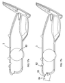
Referring to Figures 16a and 16b, the operation of the latch mechanism for
holding the hedge trimmer in either of the orientations described above will now be
described.
-
A first retaining member (81) is mounted at a first end of a bracket (85), and the
other end of bracket (85) is mounted on a compression spring (86). Compression
spring (86) is fixed to the body of the hedge trimmer housing at (87). A second
retaining member (82) is able to pivot about a pin (88), pin (88) being fixed relative to
the housing (3). Second retaining member (82) is also rigidly fixed to a first end of a
lever (89), the second end of lever (89) being slidable in a second bracket (90),
second bracket (90) being formed in first bracket (85).
-
When the first bracket (85) is moved in the direction of arrow S from the
configuration shown in Figure 16a to the configuration of Figure 16b as a result of
compression spring (86) extending, it can be seen that firstly the first retaining
member (81) is pushed out of the back of the housing (3). Secondly, as a result of
lever (89) sliding upwardly in second bracket (90), the second retaining member (82)
is pivoted about pin (88) and out of housing (3).
-
In the configuration of Figure 16b, either the first or second retaining means
(81, 82) will engage with a corresponding portion of the handle assembly (not
shown), and a user would release the mechanism simply by pushing the retaining
member which is not in engagement with the handle assembly back into the housing,
as this action would also result in retracting the other retaining member from
engagement with the handle assembly.
-
Referring to Figures 17a and 17b, the hedge trimmer housing (3) engages the
hedge trimmer handle assembly at a cylindrical pivot (80) such that the housing (3)
can rotate about pivot portion (80). The hedge trimmer can be operated in two
separate orientations, the in-line orientation as shown in Figure 2, or the orientation
shown in Figures 8 and 9 where the hedge trimmer housing (3) is rotated through 90°
relative to the hedge trimmer handle assembly (2).
-
In order to retain the hedge trimmer housing (3) in position relative to the
handle assembly (not shown), the housing (3) is provided with a first retaining
member (81) and a second retaining member (82). Both first and second retaining
members (81, 82) are retractable relative to the housing (3), and are shown in their
respective retracted positions in Figure 17a. The rear end of housing (3) has an
integrally formed abutment surface (83) shaped to receive an engaging portion (84)
of handle assembly (2). It can be seen that the engaging portion (84) of the handle
assembly is received between abutment surface (83) of the housing (3) and the first
retaining member (81) such that the engaging portion (84) can not move in either the
upwards or downwards direction relative to housing (3). The first retaining member
(81) is so shaped that the engaging portion (84) can slide into engagement with
abutment surface (83) by displacing retaining member (81), but cannot move out of
engagement with abutment surface (83) until retaining member (81) is retracted into
the housing (3).
-
When the hedge trimmer is used in the orientation shown in Figures 8 and 9,
second retaining member (82) grips a second engaging portion (not shown) of the
handle assembly, and in this orientation even though first retaining member (81) is
deployed, it is not in use. In order to release the latch mechanism, either first or
second retaining members (81, 82) can be depressed by the user, depending on
which one is not in engagement with the handle assembly, which simultaneously
moves both first and second retaining members (81, 82) into the housing.
-
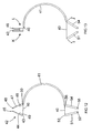
Referring to Figures 12 and 13, the dual switching mechanism of the present
invention will now be described.
-
A bowden cable, such as that used to operate the brakes on a pedal bicycle,
consists of an inner cable (40) surrounded by an outer sheath (41). The inner cable
(40) passes through the outer cable (41) and is slidable relative thereto. An electrical
contact shown generally by (42) comprises a first metallic pad (43) mounted on an
arm (44), the arm being pivotable about point (45) and a second metallic pad (46)
mounted on a second arm (47), the second arm being pivotable about point 48 such
that metallic pads (43) and (46) can be pivoted towards each other, and into contact.
-
A first end of inner cable (40) is attached to metallic pad (43) at point (49), and
a first end of outer cable (41) is attached to arm (47) at point (50).
-
A first switch (51) comprises an arm that is pivotable about point (52), the arm
being attached to a second end of inner cable (40) at point (53). A second switch
(54) is pivotable about point (55) and is attached to the outer cable at point (56).
-
Referring to Figure 13, first switch (51) and second switch (54) are operated by
a user applying pressure and pivoting them away from each other in the direction
shown by arrows I and J. As first switch (51) is rigidly attached to the inner cable
(40), and second switch (54) is rigidly attached to the outer cable (41), the pivoting
motion of the switches in opposite directions draws the inner cable (40) through outer
cable (41), whilst at the same time second switch (54) pushes outer cable (41)
around inner cable (40). As a result of this, inner cable (40) pulls first metallic pad
(43) in the direction of arrow K, and outer cable (41) pushes the second metallic pad
(46) in the direction of arrow L such that pads (43), (46) come into contact.
-
It can be seen then that if only one switch, either (51) or (54), is moved whilst
the other switch remains in the open position, the resulting movement of the bowden
cable would only consist of independent movement of either the inner (40) or outer
cable (41) such that the contact would only be half closed, as only one metallic pad
would be moved into a contacting position.
-
It should also be appreciated that further embodiments of a switching
mechanism of this type are possible with more than two switches. For example, a
single inner cable (40) can be provided with a plurality of outer sheaths (41), each
outer sheath moving independently of one another which provides the option of
adding more switches and/or electrical contacts. It should also be noted that in
practice, taking the example of a two switch mechanism, the mechanism will be set
up such that closing one switch will have the result of partially closing the contact by
more than half the distance required to fully close the contact, and closing the second
switch will also have the result of more than half closing the contact. In this way, it is
ensured that the contact will actually be closed when both switches are closed.
-
It should also be appreciated that Figures 12 and 13 are only a schematic
representation of the switching mechanism, and in practise the contacts be in the
form of something other than pivoting metallic pads, as will be described below.
-
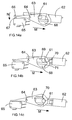
Referring to Figures 14a to 15c, the operation of the pivoting switching
mechanism will now be described.
-
Referring to Figure 14a, a pin (61) is held in a pin housing (62) which is
disposed in the hedge trimmer handle assembly (not shown). The pin (61) and pin
housing (62) are slidable relative to the hedge trimmer handle assembly (not shown)
in the direction of arrow M. Pin (61) projects outwardly from housing (62) and is
received in an aperture (68) formed in an arm member (63). Arm member (63) is
mounted to the hedge trimmer body housing (not shown) by a pin (64). Arm member
(63) is pivotable about pin (64) in the direction of arrow N relative to the hedge
trimmer housing (not shown). An electrical relay (65) is disposed in the hedge
trimmer housing (not shown) such that when arm (63) is pivoted in the direction of
arrow N, a remote end (66) of arm (63) depresses a switch (67) and closes relay
(65).
-
Referring now to Figure 14b, when a first switch (not shown), is depressed by
the user, a cable (not shown) causes pin (61) to slide in the direction of arrow M
along cam surface (69) provided in aperture (68). It can be seen, however, that the
movement of pin (61) is insufficient to cause arm member (63) to pivot about pin (64)
and close relay (65). Referring now to Figure 14c, in order to close the relay, the user
must depress a second switch (not shown) provided on the handle assembly, which
causes pin (61) to slide a further distance in the direction of arrow M along a second
cam surface (70), provided in aperture (68), causing arm member (63) to pivot about
point (64) and close the relay (65).
-
It can therefore be seen that in order to close the relay (65), a user must
depress both first and second hedge trimmer switches, which in the embodiment of
the hedge trimmer shown in Figure 4 for example, would be switch (8) formed on
front handle (6) and either one of switches (13), (14) formed on rear handle (7).
-
Referring to Figure 8, the hedge trimmer body housing (3) can be pivoted at
90□ relative to the handle assembly (2). Referring now to Figure 15a, the pin housing
(62) is rotated through 90□ from the position shown in Figure 14a. Pin (61) now
abuts third cam surface (71), and as the hedge trimmer housing has remained
stationary, arm member (63) remains in the same position.
-
Referring now to Figure 15b, when a user depresses a first switch (not shown),
in the same way as shown in Figure 14b except at 900 to figure 14b, pin (61) moves
through a first distance in the direction of arrow P from cam surface (71) to cam
surface (69). It can be seen however, that pin (61) has not moved sufficiently to pivot
arm (63) about pin (64) to close relay (65).
-
Referring now to Figure 15c, in order to close relay (65), the user must depress
a second switch (not shown) which further moves pin (61) in the direction of arrow P
thus pivoting arm (63) about pin (64) and completing the closure of relay (65).
-
Referring now to Figure 11, an electric motor (14) is disposed axially in housing
(3), such that the axis of rotation (15) of the motor output shaft (16) is parallel to the
plane of blade (5). It can be seen therefore that in order to drive the blade
mechanism, the direction of rotation about axis (15) needs to be converted through
90° into rotation about axis (17).
-
As shown in Figures 10a and 10b, the drive conversion mechanism of the
present invention for converting rotation about a first axis to rotation about a second
axis comprises a shaft (30) rotating in the direction of arrow (31). A plurality of axially
aligned parallel teeth (32) are formed at the end of shaft (30). Parallel teeth (32)
intermesh with a second plurality of radial teeth (33) formed on the upper surface of a
gear plate (34). Gear plate (34) is mounted on a second shaft (35) such that gear
plate (34) is free to rotate about an axis Z-Z. As a result of this, the rotation of shaft
(30) imparts rotation to gear plate (35) in the direction of arrow (36) due to the
reaction between teeth (32) and teeth (33).
-
This method of converting rotation about a first axis into rotation about a
second axis generally perpendicular to said first axis is substantially cheaper to
manufacture than prior art methods, as the engineering tolerances between teeth
(32) and shaft (30) and teeth (33) on the gear plate (34) can be less than those
needed to be achieved with the conical gears of the prior art drive mechanisms.
-
Referring again to Figure 11, the incorporation of the drive conversion
mechanism of Figures 10a and 10b into the hedge trimmer of the present invention
will now be described.
-
An electric motor drives a rotary output shaft (16) adapted to rotate about axis
(15). A plurality of teeth (40) are formed on the edge of shaft (16) and intermesh with
a second plurality of teeth (41) formed on a gear (42). Gear (42) is adapted to rotate
about axis (18) which is parallel to axis (15), and as gear (42) comprises a larger
number of teeth (41) than the number of teeth (40) formed on output shaft (16), the
rotational speed of gear (42) is less than that of output shaft (16). Gear (42) is
mounted on a shaft (30) which has a further set of teeth (32) formed around the edge
of shaft (30). Teeth (32) intermesh with a plurality of radial teeth (33) formed on the
upper surface of a gear plate (34). Gear plate (34) is mounted on shaft (35) and
adapted to rotate about axis (17) such that the rotation of shaft (30) about axis (18) is
converted to rotation about axis (17) generally perpendicular to axis (18).
-
It can therefore be seen that the teeth on shaft (32) can still drive gear plate
(34) despite variations in position between the shaft and the gear plate, provided the
teeth on the shaft still engage the teeth on the gear plate. The shaft and gear plate
therefore do not need to be as accurately located relative to each other as the bevel
gears of the prior art.
-
It can also be seen that the inline rotation of the motor output shaft (16) is
converted into rotation in the plane of blade (5). The blade (5) is connected to gear
plate (34) via a drive conversion mechanism for converting rotary motion about axis
(17) into linear reciprocating motion perpendicular to axis (17) in a manner which will
be familiar to persons skilled in the art, such as a scotch yoke mechanism.
Mechanisms of this type are well known in the art and will not be described herein in
any further detail.
-
It will be appreciated by persons skilled in the art that the above embodiments
have been described by way of example only and not in any limitative sense, and
that various alterations and modification are possible without departure from the
scope of the invention as defined by the appended claims.