EP1504184B1 - A stirling engine assembly - Google Patents
A stirling engine assembly Download PDFInfo
- Publication number
- EP1504184B1 EP1504184B1 EP03727659A EP03727659A EP1504184B1 EP 1504184 B1 EP1504184 B1 EP 1504184B1 EP 03727659 A EP03727659 A EP 03727659A EP 03727659 A EP03727659 A EP 03727659A EP 1504184 B1 EP1504184 B1 EP 1504184B1
- Authority
- EP
- European Patent Office
- Prior art keywords
- bellows
- stirling engine
- engine
- assembly according
- seal
- Prior art date
- Legal status (The legal status is an assumption and is not a legal conclusion. Google has not performed a legal analysis and makes no representation as to the accuracy of the status listed.)
- Expired - Lifetime
Links
- 239000000567 combustion gas Substances 0.000 claims abstract description 10
- 239000002826 coolant Substances 0.000 claims description 15
- 238000009413 insulation Methods 0.000 claims description 4
- 239000006096 absorbing agent Substances 0.000 description 10
- 239000007789 gas Substances 0.000 description 10
- 230000005540 biological transmission Effects 0.000 description 4
- 239000000725 suspension Substances 0.000 description 4
- 238000001816 cooling Methods 0.000 description 3
- 239000000919 ceramic Substances 0.000 description 2
- 230000006835 compression Effects 0.000 description 2
- 238000007906 compression Methods 0.000 description 2
- 239000007788 liquid Substances 0.000 description 2
- 230000033001 locomotion Effects 0.000 description 2
- 238000000034 method Methods 0.000 description 2
- 239000000203 mixture Substances 0.000 description 2
- 238000009825 accumulation Methods 0.000 description 1
- 230000000712 assembly Effects 0.000 description 1
- 238000000429 assembly Methods 0.000 description 1
- 230000015556 catabolic process Effects 0.000 description 1
- 239000000110 cooling liquid Substances 0.000 description 1
- 238000013016 damping Methods 0.000 description 1
- 238000006731 degradation reaction Methods 0.000 description 1
- 230000000694 effects Effects 0.000 description 1
- 239000000835 fiber Substances 0.000 description 1
- 239000000446 fuel Substances 0.000 description 1
- 238000002955 isolation Methods 0.000 description 1
- 239000000463 material Substances 0.000 description 1
- 230000010355 oscillation Effects 0.000 description 1
- 230000000717 retained effect Effects 0.000 description 1
- 230000000630 rising effect Effects 0.000 description 1
- 229910001220 stainless steel Inorganic materials 0.000 description 1
- 239000010935 stainless steel Substances 0.000 description 1
- 230000003068 static effect Effects 0.000 description 1
- 238000010792 warming Methods 0.000 description 1
- XLYOFNOQVPJJNP-UHFFFAOYSA-N water Substances O XLYOFNOQVPJJNP-UHFFFAOYSA-N 0.000 description 1
Images



Classifications
-
- F—MECHANICAL ENGINEERING; LIGHTING; HEATING; WEAPONS; BLASTING
- F02—COMBUSTION ENGINES; HOT-GAS OR COMBUSTION-PRODUCT ENGINE PLANTS
- F02G—HOT GAS OR COMBUSTION-PRODUCT POSITIVE-DISPLACEMENT ENGINE PLANTS; USE OF WASTE HEAT OF COMBUSTION ENGINES; NOT OTHERWISE PROVIDED FOR
- F02G1/00—Hot gas positive-displacement engine plants
- F02G1/04—Hot gas positive-displacement engine plants of closed-cycle type
- F02G1/043—Hot gas positive-displacement engine plants of closed-cycle type the engine being operated by expansion and contraction of a mass of working gas which is heated and cooled in one of a plurality of constantly communicating expansible chambers, e.g. Stirling cycle type engines
- F02G1/053—Component parts or details
-
- F—MECHANICAL ENGINEERING; LIGHTING; HEATING; WEAPONS; BLASTING
- F02—COMBUSTION ENGINES; HOT-GAS OR COMBUSTION-PRODUCT ENGINE PLANTS
- F02G—HOT GAS OR COMBUSTION-PRODUCT POSITIVE-DISPLACEMENT ENGINE PLANTS; USE OF WASTE HEAT OF COMBUSTION ENGINES; NOT OTHERWISE PROVIDED FOR
- F02G1/00—Hot gas positive-displacement engine plants
- F02G1/04—Hot gas positive-displacement engine plants of closed-cycle type
- F02G1/043—Hot gas positive-displacement engine plants of closed-cycle type the engine being operated by expansion and contraction of a mass of working gas which is heated and cooled in one of a plurality of constantly communicating expansible chambers, e.g. Stirling cycle type engines
- F02G1/053—Component parts or details
- F02G1/0535—Seals or sealing arrangements
-
- F—MECHANICAL ENGINEERING; LIGHTING; HEATING; WEAPONS; BLASTING
- F02—COMBUSTION ENGINES; HOT-GAS OR COMBUSTION-PRODUCT ENGINE PLANTS
- F02G—HOT GAS OR COMBUSTION-PRODUCT POSITIVE-DISPLACEMENT ENGINE PLANTS; USE OF WASTE HEAT OF COMBUSTION ENGINES; NOT OTHERWISE PROVIDED FOR
- F02G2253/00—Seals
- F02G2253/06—Bellow seals
Definitions
- the present invention relates to a Stirling engine assembly.
- the invention relates to an assembly suitable for use in a combined heat and power (chp) unit.
- a Stirling engine burner is located around the heater head at the top of the engine.
- a problem for the Stirling engine-based chp system is the need to ensure that combustion gases do not flow downwards into the room-sealed unit enclosure, causing the accumulation of potentially harmful gases. Some form of seal is therefore required between the Stirling engine and the burner casing.
- the Stirling engine When operating, the Stirling engine vibrates, due to its reciprocating components.
- a vibration reduction system incorporating various damping and absorbing components can bring the residual levels of vibration to a low level, but there is still enough to cause problems to any seal located between the vibrating engine and the stationary burner casing.
- the seal design is required to be extremely robust, operate at high temperatures, and be capable of maintaining an Adequate seal under all operating conditions, as defined by the gas appliance certification procedure.
- Some conventional seal designs are typically significantly stiffer than the engine suspension system and would, if used in the application, lead to unacceptable transmission of forces between the oscillating engine and the static burner components.
- US 5,918,463 discloses a Stirling engine with a washer shaped piece of flexible, semi rigid, or rigid fibrous ceramic insulation between the burner casing and Stirling engine.
- US 4,573,320 discloses a Stirling engine with a bellows seal to seal between a fuel nozzle and a housing in which a Stirling engine is received.
- a Stirling engine assembly comprising a Stirling engine with a hot head and a cold region, a burner arranged to provide heat to the head, and a corrugated seal between the Stirling engine and the burner to prevent the flow of combustion gases from the head into the surrounding environment, characterised in that the burner is annular and surrounds the head, and wherein the Stirling engine is supported by a mounting frame at least in part via the seal.
- the seal design can thus be made to be flexible enough to cope with the relative motion (both vertical, horizontal and rotational in nature) between engine and burner.
- suitable materials for the seal are available which can withstand the high temperatures associated with the burner gases, and are not corroded by the gases involved.
- an arrangement is provided which supports the engine which isolates a large proportion of the vibration, while, at the same time, providing a highly effective seal preventing combustion gases from escaping into the body of the chp unit casing.
- the suspension system can be made lighter as it supports less weight, or can even be removed altogether with obvious cost advantages.
- Insulation is preferably provided between the seal and the engine to substantially reduce the passage of hot combustion gases from the burner towards the bellows.
- the seal may, for example, be a bellows.
- the bellows may be arranged such that it extends from a location adjacent to the burner, along a substantial portion of the length of the Stirling engine.
- means are provided for passing coolant through the bellows to provide a flow of coolant liquid to and from an engine cooler.
- This preferably entails a coolant inlet and coolant outlet pipe extending through the bellows and being sealed by a flexible seal.
- the bellows is preferably provided in this region, with a cylindrical portion. This elongate bellows design reduces the levels of transmitted noise from the Stirling engine by providing a sealed gas cushion around the body of the engine. In the same way, however, this gas cushion may insulate the engine and reduce heat losses from the casing.
- the bellows may terminate above an engine cooler. In this case, there is no need for the coolant to pass through the bellows.
- the bellows is arranged to extend vertically, the weight of the Stirling engine is borne along the length of the bellows.
- the bellows may be arranged at an angle to the vertical.
- the weight of the Stirling engine may be borne entirely by the bellows.
- the weight of the Stirling engine is borne partially by the bellows and partially by one or more additional resilient members. Such as springs from which the engine is suspended.
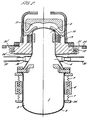
- the Stirling engine assembly comprises a Stirling engine 1 housed within a casing 2.
- the design of the Stirling engine 1 is well-known in the art.
- the engine is broadly divided into three segments, a heater head 3, a cooler 4 and an alternator 5.
- the engine has displacer and power pistons, both of which are arranged to reciprocate in a vertical direction. This produces a net vertical vibration of the Stirling engine itself.
- an annular absorber mass 6 is supported by a number of compression springs 7 both above and below the absorber mass.
- a gas/air mixture is supplied along an inlet duct 8 to a burner element 9 where it is ignited.
- the heat generated is transferred to a heater head 3 via a plurality of annular fins 10.
- the combustion gases flow up through the fins 10 around the top of the heater head and into a recuperator 11 in which they preheat the incoming gas/air mixture and subsequently heat water for domestic use.
- Ceramic fibre insulation 12 increases the resistance to downward gas flow so that very little downward gas flow occurs.
- the bellows 20 surround the Stirling engine 1.
- the bellows has an annular flange 21 which is bolted to the lower surface of the burner/recuperator assembly 22.
- This flange 21 sits on the unit frame 23.
- This frame 23 is a rigid box frame attached to the wall of a dwelling.
- the bellows 20 terminates in a lower annular flange 24 which is bolted or connected using a clamping ring to a mounting ring 25 which is welded around a lower portion of the casing 2 of the Stirling engine 1 adjacent to the alternator 5. In this way, the weight of the Stirling engine 1 including the fins 10 together with the vibration absorber 6 and its associated mountings are all supported on the unit frame 23 via the bellows 20.
- An annular coolant duct 30 surrounds the casing 2 in the vicinity of the cooler 4. This annular duct is fed with coolant liquid from an inlet pipe 31, while the outlet from the duct 30 is via outlet pipe 32.
- the inlet 31 and outlet 32 pipes extend through the wall of the bellows 20 as shown in greater detail in Fig. 1a. At this location, the wall of the bellows 20 is cylindrical and is provided with a pair of circular openings 33.
- a rigid pipe extension 34 which is screwed to the annular duct 30 passes through the opening 33.
- the inlet 31/outlet 32 pipe (as the case may be) is fastened to the rigid pipe extension 34 using a jubilee clip with a clamping ring 35.
- a seal is made using a flexible rubber grommet seal 36. This seal presses against the rigid pipe extension 34. This arrangement will allow the pipes 31/32 to vibrate without damage.
- the grommet seals 36 are in contact with the coolant pipes, the temperature in this region is low enough to allow the use of a commercially available rubber seal, giving low rates of wear for components in this area.
- FIG. 2 A second example of a Stirling engine assembly in accordance with the present invention is shown in Fig. 2. This is largely the same as the example shown in Fig. 1, with the same reference numerals having been used to designate the same components. A further description of these common components is not repeated here.
- the second example differs from the first example in that the bellows 20' terminates above the cooler 4.
- the upper mounting is the same as for the first example, but the lower mounting is via a mounting plate 24' welded around the casing 2 above the cooler 4.
- neither the annular absorber mass 6, nor the annular coolant duct 30 are within the bellows. There is therefore no need to provide an interface between the coolant inlet 31/outlet 32 pipes and the bellows.
- the bellows 20 consists of a flexible stainless steel (AISI 32 or AISI 316Ti) tube with annular corrugated convolutions.
- the most cost effective cross-sectional shape of bellows is the rounded-end section of Figs. 1 and 2 and as shown in more detail in Fig. 3a. These are made by a hydraulic forming process.
- the cross-section may have sharp edges 40 which are each welded.
- the rounded section bellows also has more advantageous properties in terms of allowing relative lateral movement between its ends. This can be important where vibrational forces produced by the Stirling engine can be horizontal as well as vertical and reduces transmission of forces within the system.
- the weight of the Stirling engine 1 and absorber mass 6 is 20 to 100 kilograms.
- the stiffness of the bellows is adjusted to match the engine weight and also the space available for allowable extension.
- Fig. 1 For the engine of Fig. 1 there will be 3 to 4 convolutions above the cooler 4 and 12 to 18 convolutions beneath the cooler 4. In the short bellows of Fig. 2, there will be typically 3 to 4 convolutions.
- the stiffness per convolution is 380N/mm to 50N/mm for a 60 kilogram engine. The stiffness per convolution is varied by altering the outside diameter of the bellows, while keeping the inside diameter constant. Lower stiffness has the advantage of reducing vibration levels, but needs to be balanced against the additional weight and the extra space needed around the engine.
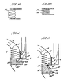
- Fig. 4 shows an annular disc 20'' with concentric annular convolutions which are convoluted in a direction perpendicular to the plane of the disc.
- mounting plate 24" has an upwardly extending annular flange 50, while a downwardly annular flange 51 depends from the casing of the burner 9.
- the seal 20' ' is mounted between these two flanges and held in place with annular clips 52.
- Such an arrangement is not capable of supporting any of the weight of the engine and is therefore not a part of the present invention.
- the seal 20 may bear some of the weight of the Stirling engine 1 and absorber mass 6, while some additional suspension for the Stirling engine 1 and absorber mass 6 is provided.
- This may be in the form of a plurality of springs 60 which are arranged around the engine and are attached between the unit frame 23 and the lower flange 24. This allows the size and therefore the weight and cost of the bellows to be reduced. In this case, spring failure would not be as serious as failure of the bellows suspension, so that this arrangement reduces risk of costly chp downtime.
- Fig. 6 is shown with a bellows similar to that in Fig. 2, it would also be possible to use any of the alternative configurations of Figs. 1 and 3 to 5.
- Fig. 7 shows a Stirling engine assembly in which the Stirling engine is mounted horizontally. Most aspects of the Stirling engine assembly are similar to that shown in Fig. 2 and are not described in further detail here. In this case, the bellows 20 is acting purely as a seal and does not bear any weight of the Stirling engine assembly. This example therefore does not form part of the present invention.
- the annular disc 20" of Fig. 4 is particularly suited to this type of horizontal mounting.
- a support 70 This comprises two arcuate brackets 71, 72 attached to the engine 1 adjacent to the cooler 4 and to the end of the alternator 5 respectively. Cooling passages 73 within the brackets 71, 72 permit the flow of air and prevent the temperature of the casing 2 adjacent to the alternator from rising to unacceptable levels. Legs 74 extend from each of arcuate bracket into a base 75 in which they are retained in by rubber seats 76 to reduce the transmission of vibration to the base 75.
Landscapes
- Engineering & Computer Science (AREA)
- Chemical & Material Sciences (AREA)
- Combustion & Propulsion (AREA)
- Mechanical Engineering (AREA)
- General Engineering & Computer Science (AREA)
- Sealing Devices (AREA)
- Telephone Function (AREA)
- Valve-Gear Or Valve Arrangements (AREA)
- Vibration Prevention Devices (AREA)
- Diaphragms And Bellows (AREA)
- Magnetic Bearings And Hydrostatic Bearings (AREA)
Abstract
Description
- The present invention relates to a Stirling engine assembly. In particular, the invention relates to an assembly suitable for use in a combined heat and power (chp) unit.
- Where an appliance, such as a chp unit, is installed in a domestic environment, it is vital that noise and vibration that could cause a considerable nuisance, is kept to a very low level. As the appliance contains a Stirling engine, combined with an alternator, it produces a considerably higher level of noise and vibration than would be acceptable. It is therefore necessary to minimise the transmission of noise and vibration to the domestic environment, through the casing and support frame of the combined heat and power unit.
- A Stirling engine burner is located around the heater head at the top of the engine. A problem for the Stirling engine-based chp system is the need to ensure that combustion gases do not flow downwards into the room-sealed unit enclosure, causing the accumulation of potentially harmful gases. Some form of seal is therefore required between the Stirling engine and the burner casing.
- When operating, the Stirling engine vibrates, due to its reciprocating components. A vibration reduction system, incorporating various damping and absorbing components can bring the residual levels of vibration to a low level, but there is still enough to cause problems to any seal located between the vibrating engine and the stationary burner casing. The seal design is required to be extremely robust, operate at high temperatures, and be capable of maintaining an Adequate seal under all operating conditions, as defined by the gas appliance certification procedure. Some conventional seal designs are typically significantly stiffer than the engine suspension system and would, if used in the application, lead to unacceptable transmission of forces between the oscillating engine and the static burner components.
- Excessive wear, fatigue or degradation of such seal would cause combustion gases to leak into the unit enclosure, causing a hazard, and increasing noise levels.
- US 5,918,463 discloses a Stirling engine with a washer shaped piece of flexible, semi rigid, or rigid fibrous ceramic insulation between the burner casing and Stirling engine. US 4,573,320 discloses a Stirling engine with a bellows seal to seal between a fuel nozzle and a housing in which a Stirling engine is received.
- The usual practice is to support an engine by mounting it on top of springs, which isolate a large proportion of the vibration produced during normal engine operation. An example of a Stirling engine having such an arrangement is US 4,400,941. To maximise the degree of isolation, a low stiffness mounting system is required. The implementation of this, with compression springs, can lead to instability, especially where the forces involved are lateral in nature in addition to vertical oscillations. An alternative support arrangement is therefore necessary. Our previous patent application PCT/GB 02/05111 details a solution to this problem, where springs are arranged around the outer surface of the Stirling engine, to suspend the engine from a mounting flange.
- According to the present invention, there is provided a Stirling engine assembly comprising a Stirling engine with a hot head and a cold region, a burner arranged to provide heat to the head, and a corrugated seal between the Stirling engine and the burner to prevent the flow of combustion gases from the head into the surrounding environment, characterised in that the burner is annular and surrounds the head, and wherein the Stirling engine is supported by a mounting frame at least in part via the seal.
- The seal design can thus be made to be flexible enough to cope with the relative motion (both vertical, horizontal and rotational in nature) between engine and burner. In addition, suitable materials for the seal are available which can withstand the high temperatures associated with the burner gases, and are not corroded by the gases involved.
- By supporting the Stirling engine by a mounting frame at least in part via the seal, an arrangement is provided which supports the engine which isolates a large proportion of the vibration, while, at the same time, providing a highly effective seal preventing combustion gases from escaping into the body of the chp unit casing.
- As part of the weight of the Stirling engine is supported by the seal, the suspension system can be made lighter as it supports less weight, or can even be removed altogether with obvious cost advantages.
- Insulation is preferably provided between the seal and the engine to substantially reduce the passage of hot combustion gases from the burner towards the bellows.
- The seal may, for example, be a bellows.
- The bellows may be arranged such that it extends from a location adjacent to the burner, along a substantial portion of the length of the Stirling engine. In this case, means are provided for passing coolant through the bellows to provide a flow of coolant liquid to and from an engine cooler. This preferably entails a coolant inlet and coolant outlet pipe extending through the bellows and being sealed by a flexible seal. The bellows is preferably provided in this region, with a cylindrical portion. This elongate bellows design reduces the levels of transmitted noise from the Stirling engine by providing a sealed gas cushion around the body of the engine. In the same way, however, this gas cushion may insulate the engine and reduce heat losses from the casing. As the alternator, in particular, relies on air cooling around the lower engine/absorber casing to maintain the temperature of the magnet at an operational level, this may be disadvantageous. To overcome this, it is possible to add cooling fins to the exposed lower end of the engine to aid heat loss, thereby compensating for the warming effect of the bellows.
- As an alternative to the bellows extending along a substantial length of the engine, the bellows may terminate above an engine cooler. In this case, there is no need for the coolant to pass through the bellows.
- If the bellows is arranged to extend vertically, the weight of the Stirling engine is borne along the length of the bellows. However, the bellows may be arranged at an angle to the vertical.
- The weight of the Stirling engine may be borne entirely by the bellows. Alternatively, the weight of the Stirling engine is borne partially by the bellows and partially by one or more additional resilient members. Such as springs from which the engine is suspended.
- Examples of Stirling engine assemblies in accordance with the present invention will now be described with reference to the accompanying drawings, in which:
- Fig. 1 is a schematic section of a first example;
- Fig. 1a shows a portion of Fig. 1 in greater detail;
- Fig. 2 is a view similar to Fig. 1 showing a second example;
- Figs. 3a and 3b are cross-sections of alternative bellows sections;
- Fig. 4 is a cross-section through part of a Stirling engine showing an alternative seal configuration which is not in accordance with the present invention;
- Fig. 5 is a view similar to Fig. 4 showing a further bellows arrangement;
- Fig. 6 is a view similar to Fig. 2 showing a third example;
- Fig. 7 is a view similar to Fig. 2 showing an example which is not in accordance with the invention; and
- Fig. 8 is a section through line VIII - VIII in Fig. 7.
- The Stirling engine assembly comprises a Stirling
engine 1 housed within a casing 2. The design of the Stirlingengine 1 is well-known in the art. The engine is broadly divided into three segments, aheater head 3, a cooler 4 and an alternator 5. The engine has displacer and power pistons, both of which are arranged to reciprocate in a vertical direction. This produces a net vertical vibration of the Stirling engine itself. In order to reduce this vibration, an annular absorber mass 6 is supported by a number ofcompression springs 7 both above and below the absorber mass. - In order to transfer heat to the
heater head 3, a gas/air mixture is supplied along an inlet duct 8 to a burner element 9 where it is ignited. The heat generated is transferred to aheater head 3 via a plurality ofannular fins 10. The combustion gases flow up through thefins 10 around the top of the heater head and into arecuperator 11 in which they preheat the incoming gas/air mixture and subsequently heat water for domestic use.Ceramic fibre insulation 12 increases the resistance to downward gas flow so that very little downward gas flow occurs. - The combustion gases are prevented from escaping into the external environment by the presence of an annular seal in the form of
bellows 20 surrounding theStirling engine 1. At its top end, the bellows has anannular flange 21 which is bolted to the lower surface of the burner/recuperator assembly 22. Thisflange 21 sits on theunit frame 23. Thisframe 23 is a rigid box frame attached to the wall of a dwelling. At its lower end, thebellows 20 terminates in a lowerannular flange 24 which is bolted or connected using a clamping ring to a mountingring 25 which is welded around a lower portion of the casing 2 of theStirling engine 1 adjacent to the alternator 5. In this way, the weight of theStirling engine 1 including thefins 10 together with the vibration absorber 6 and its associated mountings are all supported on theunit frame 23 via the bellows 20. - In order to circulate cooling liquid around the cooler 4, it is necessary to provide flow of coolant to and from the cooler. An
annular coolant duct 30 surrounds the casing 2 in the vicinity of the cooler 4. This annular duct is fed with coolant liquid from aninlet pipe 31, while the outlet from theduct 30 is viaoutlet pipe 32. Theinlet 31 andoutlet 32 pipes extend through the wall of thebellows 20 as shown in greater detail in Fig. 1a. At this location, the wall of thebellows 20 is cylindrical and is provided with a pair ofcircular openings 33. Arigid pipe extension 34 which is screwed to theannular duct 30 passes through theopening 33. Theinlet 31/outlet 32 pipe (as the case may be) is fastened to therigid pipe extension 34 using a jubilee clip with a clampingring 35. At eachopening 33, a seal is made using a flexiblerubber grommet seal 36. This seal presses against therigid pipe extension 34. This arrangement will allow thepipes 31/32 to vibrate without damage. As the grommet seals 36 are in contact with the coolant pipes, the temperature in this region is low enough to allow the use of a commercially available rubber seal, giving low rates of wear for components in this area. - As it is not intended that the Stirling engine should be serviced on site, there is no requirement for access to the components that will be sealed within the
bellows 20. If an engine failure occurs, the engine will be removed, repaired and replaced as a single module (including bellows). Therigid pipe extensions 34 and grommet seals 33 could, however, be replaced at service intervals. - A second example of a Stirling engine assembly in accordance with the present invention is shown in Fig. 2. This is largely the same as the example shown in Fig. 1, with the same reference numerals having been used to designate the same components. A further description of these common components is not repeated here.
- The second example differs from the first example in that the bellows 20' terminates above the cooler 4. In this case, the upper mounting is the same as for the first example, but the lower mounting is via a mounting plate 24' welded around the casing 2 above the cooler 4. In this case, neither the annular absorber mass 6, nor the
annular coolant duct 30 are within the bellows. There is therefore no need to provide an interface between thecoolant inlet 31/outlet 32 pipes and the bellows. - With this arrangement, the
Stirling engine 1 including thefins 10 together with the vibration absorber 6 are suspended from theunit frame 23 via the bellows 20'. - The bellows 20 consists of a flexible stainless steel (
AISI 32 or AISI 316Ti) tube with annular corrugated convolutions. The most cost effective cross-sectional shape of bellows is the rounded-end section of Figs. 1 and 2 and as shown in more detail in Fig. 3a. These are made by a hydraulic forming process. Alternatively, the cross-section may havesharp edges 40 which are each welded. The rounded section bellows also has more advantageous properties in terms of allowing relative lateral movement between its ends. This can be important where vibrational forces produced by the Stirling engine can be horizontal as well as vertical and reduces transmission of forces within the system. - Typically, the weight of the
Stirling engine 1 and absorber mass 6 is 20 to 100 kilograms. The stiffness of the bellows is adjusted to match the engine weight and also the space available for allowable extension. - Typically, for the engine of Fig. 1 there will be 3 to 4 convolutions above the
cooler 4 and 12 to 18 convolutions beneath the cooler 4. In the short bellows of Fig. 2, there will be typically 3 to 4 convolutions. The stiffness per convolution is 380N/mm to 50N/mm for a 60 kilogram engine. The stiffness per convolution is varied by altering the outside diameter of the bellows, while keeping the inside diameter constant. Lower stiffness has the advantage of reducing vibration levels, but needs to be balanced against the additional weight and the extra space needed around the engine. - Alternatives to the vertically extending bellows are shown in Figs. 4 and 5. These examples are, in all other ways, similar to Fig. 2.
- Fig. 4 shows an annular disc 20'' with concentric annular convolutions which are convoluted in a direction perpendicular to the plane of the disc. In this case, mounting
plate 24" has an upwardly extending annular flange 50, while a downwardlyannular flange 51 depends from the casing of the burner 9. The seal 20' ' is mounted between these two flanges and held in place withannular clips 52. Such an arrangement, however, is not capable of supporting any of the weight of the engine and is therefore not a part of the present invention. - A similar arrangement is shown in Fig. 5, but in this case the seal is a bellows 20''' which is angled at around 45° to the horizontal.
- In the examples described to date, all of the weight of the
Stirling engine 1 and absorber mass 6 is suspended through theseal 20. As an alternative, as shown in Fig. 6 the seal may bear some of the weight of theStirling engine 1 and absorber mass 6, while some additional suspension for theStirling engine 1 and absorber mass 6 is provided. This may be in the form of a plurality of springs 60 which are arranged around the engine and are attached between theunit frame 23 and thelower flange 24. This allows the size and therefore the weight and cost of the bellows to be reduced. In this case, spring failure would not be as serious as failure of the bellows suspension, so that this arrangement reduces risk of costly chp downtime. However, the weight and cost reduction of the seal must be balanced against the additional components required with this arrangement with their associated additional weight and cost. Although Fig. 6 is shown with a bellows similar to that in Fig. 2, it would also be possible to use any of the alternative configurations of Figs. 1 and 3 to 5. - Fig. 7 shows a Stirling engine assembly in which the Stirling engine is mounted horizontally. Most aspects of the Stirling engine assembly are similar to that shown in Fig. 2 and are not described in further detail here. In this case, the
bellows 20 is acting purely as a seal and does not bear any weight of the Stirling engine assembly. This example therefore does not form part of the present invention. Theannular disc 20" of Fig. 4 is particularly suited to this type of horizontal mounting. - Instead, the weight of the assembly is carried by a
support 70. This comprises twoarcuate brackets 71, 72 attached to theengine 1 adjacent to the cooler 4 and to the end of the alternator 5 respectively. Coolingpassages 73 within thebrackets 71, 72 permit the flow of air and prevent the temperature of the casing 2 adjacent to the alternator from rising to unacceptable levels.Legs 74 extend from each of arcuate bracket into a base 75 in which they are retained in byrubber seats 76 to reduce the transmission of vibration to thebase 75.
Claims (13)
- A Stirling engine assembly comprising a Stirling engine with a hot head (3) and a cold region (4), a burner (9) arranged to provide heat to the head, and a corrugated seal (20, 20', 20'', 20''') between the Stirling engine and the burner to prevent the flow of combustion gases from the head into the surrounding environment, characterised in that the burner is annular and surrounds the head, and wherein the Stirling engine is supported by a mounting frame (21) at least in part via the seal.
- A Stirling engine assembly according to claim 1, wherein the seal (20, 20', 20'', 20''') is a bellows.
- A Stirling engine assembly according to claim 2, wherein insulation (12) is provided between the bellows (20, 20', 20'', 20''') and the engine to substantially reduce the passage of hot combustion gases from the burner towards the seal.
- An assembly according to claim 2 or 3, wherein the bellows (20) extends from a location adjacent to the burner (9), along a substantial portion of the length of the Stirling engine.
- An assembly according to claim 4, wherein means (31,32) are provided for passing coolant through the bellows (20) to provide a flow of coolant to and from an engine cooler.
- An assembly according to claim 5, further comprising a coolant inlet (31) and a coolant outlet (32) pipe extending through the bellows (20) and being sealed by a flexible seal.
- An assembly according to claim 4 or claim 5, wherein the bellows (20) is cylindrical in the region of the engine cooler.
- An assembly according to claim 2, wherein the bellows (20', 20'', 20''') terminate above the engine cooler.
- An assembly according to any one of claims 2 to 8, wherein the bellows (20, 20') is arranged to extend vertically such that the weight of the Stirling engine is borne along the length of the bellows.
- An assembly according to any one of claims 2 to 8, wherein the bellows (20''') is arranged at an angle to the vertical.
- An assembly according to claim 2, wherein the weight of the engine is borne entirely by the bellows (20, 20', 20'', 20''').
- An assembly as according to claim 2, wherein the weight of the Stirling engine is borne partially by the bellows (20, 20', 20'', 20''') and partially by one or more additional resilient members (60).
- An assembly according to claim 11, wherein the additional resilient members are springs (60) from which the engine is suspended.
Applications Claiming Priority (3)
| Application Number | Priority Date | Filing Date | Title |
|---|---|---|---|
| GBGB0210929.6A GB0210929D0 (en) | 2002-05-13 | 2002-05-13 | A stirling engine assembly |
| GB0210929 | 2002-05-13 | ||
| PCT/GB2003/002058 WO2003095822A1 (en) | 2002-05-13 | 2003-05-13 | A stirling engine assembly |
Publications (2)
| Publication Number | Publication Date |
|---|---|
| EP1504184A1 EP1504184A1 (en) | 2005-02-09 |
| EP1504184B1 true EP1504184B1 (en) | 2007-01-24 |
Family
ID=9936567
Family Applications (1)
| Application Number | Title | Priority Date | Filing Date |
|---|---|---|---|
| EP03727659A Expired - Lifetime EP1504184B1 (en) | 2002-05-13 | 2003-05-13 | A stirling engine assembly |
Country Status (11)
| Country | Link |
|---|---|
| US (1) | US7021054B2 (en) |
| EP (1) | EP1504184B1 (en) |
| JP (1) | JP4243585B2 (en) |
| CN (1) | CN100578007C (en) |
| AT (1) | ATE352712T1 (en) |
| AU (1) | AU2003233897A1 (en) |
| CA (1) | CA2486082A1 (en) |
| DE (1) | DE60311452T2 (en) |
| GB (1) | GB0210929D0 (en) |
| RU (1) | RU2004136321A (en) |
| WO (1) | WO2003095822A1 (en) |
Families Citing this family (21)
| Publication number | Priority date | Publication date | Assignee | Title |
|---|---|---|---|---|
| CA2518438A1 (en) * | 2003-03-28 | 2004-10-07 | Microgen Energy Limited | A combined heat and power system |
| GB0310999D0 (en) * | 2003-05-13 | 2003-06-18 | Microgen Energy Ltd | A domestic combined heat and power assembly |
| GB2406619A (en) * | 2003-10-02 | 2005-04-06 | Rolls Royce Plc | An appliance in combination with a co-generation system incorporating a Stirling engine |
| JP4352459B2 (en) * | 2004-05-14 | 2009-10-28 | ツインバード工業株式会社 | Stirling cycle engine suspension structure |
| GB0512672D0 (en) * | 2005-06-21 | 2005-07-27 | Microgen Energy Ltd | A stirling engine assembly and methods of assembling such an assembly |
| GB0700141D0 (en) * | 2007-01-04 | 2007-02-14 | Microgen Energy Ltd | A stirling engine system and operating method |
| JP4729533B2 (en) * | 2007-05-23 | 2011-07-20 | リンナイ株式会社 | Power generator |
| US20100083653A1 (en) * | 2008-10-03 | 2010-04-08 | Freudenberg-Nok General Partnership | Mass Damper |
| US8096118B2 (en) * | 2009-01-30 | 2012-01-17 | Williams Jonathan H | Engine for utilizing thermal energy to generate electricity |
| US8597384B2 (en) * | 2009-09-25 | 2013-12-03 | General Electric Company | Gasification cooling system having seal |
| GB2478949A (en) * | 2010-03-24 | 2011-09-28 | Bosch Gmbh Robert | Over-pressure seal between Stirling engine and combustion chamber |
| CN103967998B (en) * | 2014-04-30 | 2016-08-17 | 宁波华斯特林电机制造有限公司 | A kind of Stirling motor shock-absorbing device |
| EP3001021B1 (en) | 2014-09-25 | 2020-06-24 | United Technologies Corporation | Hail screen in the inlet of a conduit to a heat exhanger of an aircraft engine |
| GB2536333A (en) * | 2015-02-03 | 2016-09-14 | Fluid Energy Solutions Int Ltd | Sealing unit and fluid engine |
| CN106089487A (en) * | 2016-08-19 | 2016-11-09 | 宋日升 | A kind of welding bellows formula heat engine acting unit |
| CN108105328A (en) * | 2018-02-09 | 2018-06-01 | 杨厚成 | A kind of inner housing for acoustic energy refrigeration machine |
| CN108225066B (en) * | 2018-04-02 | 2024-04-19 | 宁波华斯特林电机制造有限公司 | Loading equipment for surface low-temperature test |
| CN108301937B (en) * | 2018-04-02 | 2024-06-11 | 宁波华斯特林电机制造有限公司 | A new suspension structure for Stirling motor |
| CN108716547B (en) * | 2018-07-19 | 2023-12-08 | 南京西普国际工程有限公司 | Flexible sealing device for air chamber |
| CN112498531B (en) * | 2020-11-30 | 2022-05-17 | 浙江嘉宏运动器材有限公司 | Multistage buffering anti-bumping bicycle cushion rod |
| WO2022195556A1 (en) | 2021-03-19 | 2022-09-22 | Hurst Ronald Alan | Heat engines and heat pumps with separators and displacers |
Family Cites Families (13)
| Publication number | Priority date | Publication date | Assignee | Title |
|---|---|---|---|---|
| US3530681A (en) * | 1968-08-05 | 1970-09-29 | Hughes Aircraft Co | Hydraulically driven cryogenic refrigerator |
| NL7200483A (en) * | 1972-01-13 | 1973-07-17 | ||
| US4055953A (en) * | 1973-10-31 | 1977-11-01 | U.S. Philips Corporation | Hot-gas reciprocating engine |
| US3984982A (en) * | 1975-06-06 | 1976-10-12 | Thermo Electron Corporation | Annular tidal regenerator heat engine |
| SE417448B (en) * | 1979-06-19 | 1981-03-16 | Cmc Ab | MODULE FOR BUILDING A DOUBLE-OPERATING, FOUR-CYCLE-STIRLING ENGINE |
| US4253303A (en) * | 1979-10-01 | 1981-03-03 | Liljequist Jon L | Engines, and particularly those incorporating the Stirling cycle |
| US4381648A (en) * | 1980-12-29 | 1983-05-03 | North American Philips Corporation | Stirling cycle apparatus with metal bellows seal |
| FR2528109A1 (en) * | 1982-06-04 | 1983-12-09 | Creusot Loire | STIRLING CYCLE MACHINE |
| US4573320A (en) * | 1985-05-03 | 1986-03-04 | Mechanical Technology Incorporated | Combustion system |
| US4870821A (en) * | 1985-07-02 | 1989-10-03 | Matsushita Electric Industrial Co., Ltd. | Reciprocation apparatus with sealing mechanism |
| US4723410A (en) * | 1985-10-22 | 1988-02-09 | Otters John L | Safety improvements in high pressure thermal machines |
| JPS62118046A (en) * | 1985-11-18 | 1987-05-29 | Matsushita Electric Ind Co Ltd | starling engine |
| US4774808A (en) * | 1987-07-06 | 1988-10-04 | Otters John L | Displacer arrangement for external combustion engines |
-
2002
- 2002-05-13 GB GBGB0210929.6A patent/GB0210929D0/en not_active Ceased
-
2003
- 2003-05-13 DE DE60311452T patent/DE60311452T2/en not_active Expired - Lifetime
- 2003-05-13 AU AU2003233897A patent/AU2003233897A1/en not_active Abandoned
- 2003-05-13 AT AT03727659T patent/ATE352712T1/en not_active IP Right Cessation
- 2003-05-13 JP JP2004503791A patent/JP4243585B2/en not_active Expired - Fee Related
- 2003-05-13 WO PCT/GB2003/002058 patent/WO2003095822A1/en not_active Ceased
- 2003-05-13 US US10/514,297 patent/US7021054B2/en not_active Expired - Lifetime
- 2003-05-13 CA CA002486082A patent/CA2486082A1/en not_active Abandoned
- 2003-05-13 RU RU2004136321/06A patent/RU2004136321A/en not_active Application Discontinuation
- 2003-05-13 CN CN03811003A patent/CN100578007C/en not_active Expired - Fee Related
- 2003-05-13 EP EP03727659A patent/EP1504184B1/en not_active Expired - Lifetime
Also Published As
| Publication number | Publication date |
|---|---|
| AU2003233897A1 (en) | 2003-11-11 |
| US20050166590A1 (en) | 2005-08-04 |
| CN1653257A (en) | 2005-08-10 |
| DE60311452T2 (en) | 2007-11-08 |
| ATE352712T1 (en) | 2007-02-15 |
| DE60311452D1 (en) | 2007-03-15 |
| GB0210929D0 (en) | 2002-06-19 |
| CA2486082A1 (en) | 2003-11-20 |
| CN100578007C (en) | 2010-01-06 |
| US7021054B2 (en) | 2006-04-04 |
| WO2003095822A1 (en) | 2003-11-20 |
| EP1504184A1 (en) | 2005-02-09 |
| RU2004136321A (en) | 2005-06-10 |
| JP4243585B2 (en) | 2009-03-25 |
| JP2005525499A (en) | 2005-08-25 |
Similar Documents
| Publication | Publication Date | Title |
|---|---|---|
| US7021054B2 (en) | Stirling engine assembly | |
| JP2006521499A (en) | Combined heat and power system | |
| EP1504183B1 (en) | A stirling engine assembly | |
| EP1444432B1 (en) | A stirling engine assembly | |
| KR20090028783A (en) | Combined heat and power generation system for home | |
| KR20060013391A (en) | Household Cogeneration Assembly | |
| JP4937100B2 (en) | Anti-vibration support device for Stirling engine | |
| US7789318B2 (en) | Wall mounted domestic combined heat and power appliance | |
| KR20050020962A (en) | A Stirling Engine Assembly | |
| KR100964910B1 (en) | Stirling engine assembly | |
| JP2005504225A (en) | Stirling engine assembly | |
| AU2002339146A1 (en) | A stirling engine assembly | |
| GB2484720A (en) | Micro combined heat and power appliance with a mounting spring arrangement. |
Legal Events
| Date | Code | Title | Description |
|---|---|---|---|
| PUAI | Public reference made under article 153(3) epc to a published international application that has entered the european phase |
Free format text: ORIGINAL CODE: 0009012 |
|
| 17P | Request for examination filed |
Effective date: 20041110 |
|
| AK | Designated contracting states |
Kind code of ref document: A1 Designated state(s): AT BE BG CH CY CZ DE DK EE ES FI FR GB GR HU IE IT LI LU MC NL PT RO SE SI SK TR |
|
| AX | Request for extension of the european patent |
Extension state: AL LT LV MK |
|
| 17Q | First examination report despatched |
Effective date: 20050221 |
|
| DAX | Request for extension of the european patent (deleted) | ||
| GRAP | Despatch of communication of intention to grant a patent |
Free format text: ORIGINAL CODE: EPIDOSNIGR1 |
|
| GRAS | Grant fee paid |
Free format text: ORIGINAL CODE: EPIDOSNIGR3 |
|
| GRAA | (expected) grant |
Free format text: ORIGINAL CODE: 0009210 |
|
| AK | Designated contracting states |
Kind code of ref document: B1 Designated state(s): AT BE BG CH CY CZ DE DK EE ES FI FR GB GR HU IE IT LI LU MC NL PT RO SE SI SK TR |
|
| PG25 | Lapsed in a contracting state [announced via postgrant information from national office to epo] |
Ref country code: LI Free format text: LAPSE BECAUSE OF FAILURE TO SUBMIT A TRANSLATION OF THE DESCRIPTION OR TO PAY THE FEE WITHIN THE PRESCRIBED TIME-LIMIT Effective date: 20070124 Ref country code: DK Free format text: LAPSE BECAUSE OF FAILURE TO SUBMIT A TRANSLATION OF THE DESCRIPTION OR TO PAY THE FEE WITHIN THE PRESCRIBED TIME-LIMIT Effective date: 20070124 Ref country code: AT Free format text: LAPSE BECAUSE OF FAILURE TO SUBMIT A TRANSLATION OF THE DESCRIPTION OR TO PAY THE FEE WITHIN THE PRESCRIBED TIME-LIMIT Effective date: 20070124 Ref country code: FI Free format text: LAPSE BECAUSE OF FAILURE TO SUBMIT A TRANSLATION OF THE DESCRIPTION OR TO PAY THE FEE WITHIN THE PRESCRIBED TIME-LIMIT Effective date: 20070124 Ref country code: SI Free format text: LAPSE BECAUSE OF FAILURE TO SUBMIT A TRANSLATION OF THE DESCRIPTION OR TO PAY THE FEE WITHIN THE PRESCRIBED TIME-LIMIT Effective date: 20070124 Ref country code: CH Free format text: LAPSE BECAUSE OF FAILURE TO SUBMIT A TRANSLATION OF THE DESCRIPTION OR TO PAY THE FEE WITHIN THE PRESCRIBED TIME-LIMIT Effective date: 20070124 |
|
| REG | Reference to a national code |
Ref country code: GB Ref legal event code: FG4D |
|
| REG | Reference to a national code |
Ref country code: CH Ref legal event code: EP |
|
| REG | Reference to a national code |
Ref country code: IE Ref legal event code: FG4D |
|
| REF | Corresponds to: |
Ref document number: 60311452 Country of ref document: DE Date of ref document: 20070315 Kind code of ref document: P |
|
| PG25 | Lapsed in a contracting state [announced via postgrant information from national office to epo] |
Ref country code: SE Free format text: LAPSE BECAUSE OF FAILURE TO SUBMIT A TRANSLATION OF THE DESCRIPTION OR TO PAY THE FEE WITHIN THE PRESCRIBED TIME-LIMIT Effective date: 20070424 |
|
| PG25 | Lapsed in a contracting state [announced via postgrant information from national office to epo] |
Ref country code: BG Free format text: LAPSE BECAUSE OF EXPIRATION OF PROTECTION Effective date: 20070425 |
|
| PG25 | Lapsed in a contracting state [announced via postgrant information from national office to epo] |
Ref country code: ES Free format text: LAPSE BECAUSE OF FAILURE TO SUBMIT A TRANSLATION OF THE DESCRIPTION OR TO PAY THE FEE WITHIN THE PRESCRIBED TIME-LIMIT Effective date: 20070505 |
|
| PG25 | Lapsed in a contracting state [announced via postgrant information from national office to epo] |
Ref country code: PT Free format text: LAPSE BECAUSE OF FAILURE TO SUBMIT A TRANSLATION OF THE DESCRIPTION OR TO PAY THE FEE WITHIN THE PRESCRIBED TIME-LIMIT Effective date: 20070625 |
|
| REG | Reference to a national code |
Ref country code: CH Ref legal event code: PL |
|
| ET | Fr: translation filed | ||
| PG25 | Lapsed in a contracting state [announced via postgrant information from national office to epo] |
Ref country code: SK Free format text: LAPSE BECAUSE OF FAILURE TO SUBMIT A TRANSLATION OF THE DESCRIPTION OR TO PAY THE FEE WITHIN THE PRESCRIBED TIME-LIMIT Effective date: 20070124 |
|
| PLBE | No opposition filed within time limit |
Free format text: ORIGINAL CODE: 0009261 |
|
| STAA | Information on the status of an ep patent application or granted ep patent |
Free format text: STATUS: NO OPPOSITION FILED WITHIN TIME LIMIT |
|
| 26N | No opposition filed |
Effective date: 20071025 |
|
| PG25 | Lapsed in a contracting state [announced via postgrant information from national office to epo] |
Ref country code: RO Free format text: LAPSE BECAUSE OF FAILURE TO SUBMIT A TRANSLATION OF THE DESCRIPTION OR TO PAY THE FEE WITHIN THE PRESCRIBED TIME-LIMIT Effective date: 20070124 Ref country code: CZ Free format text: LAPSE BECAUSE OF FAILURE TO SUBMIT A TRANSLATION OF THE DESCRIPTION OR TO PAY THE FEE WITHIN THE PRESCRIBED TIME-LIMIT Effective date: 20070124 Ref country code: BE Free format text: LAPSE BECAUSE OF FAILURE TO SUBMIT A TRANSLATION OF THE DESCRIPTION OR TO PAY THE FEE WITHIN THE PRESCRIBED TIME-LIMIT Effective date: 20070124 |
|
| PG25 | Lapsed in a contracting state [announced via postgrant information from national office to epo] |
Ref country code: MC Free format text: LAPSE BECAUSE OF NON-PAYMENT OF DUE FEES Effective date: 20070531 |
|
| PG25 | Lapsed in a contracting state [announced via postgrant information from national office to epo] |
Ref country code: IT Free format text: LAPSE BECAUSE OF FAILURE TO SUBMIT A TRANSLATION OF THE DESCRIPTION OR TO PAY THE FEE WITHIN THE PRESCRIBED TIME-LIMIT Effective date: 20070124 Ref country code: GR Free format text: LAPSE BECAUSE OF FAILURE TO SUBMIT A TRANSLATION OF THE DESCRIPTION OR TO PAY THE FEE WITHIN THE PRESCRIBED TIME-LIMIT Effective date: 20070425 |
|
| PG25 | Lapsed in a contracting state [announced via postgrant information from national office to epo] |
Ref country code: IE Free format text: LAPSE BECAUSE OF NON-PAYMENT OF DUE FEES Effective date: 20070514 |
|
| PG25 | Lapsed in a contracting state [announced via postgrant information from national office to epo] |
Ref country code: EE Free format text: LAPSE BECAUSE OF FAILURE TO SUBMIT A TRANSLATION OF THE DESCRIPTION OR TO PAY THE FEE WITHIN THE PRESCRIBED TIME-LIMIT Effective date: 20070124 |
|
| REG | Reference to a national code |
Ref country code: GB Ref legal event code: 732E Free format text: REGISTERED BETWEEN 20090521 AND 20090527 |
|
| PG25 | Lapsed in a contracting state [announced via postgrant information from national office to epo] |
Ref country code: CY Free format text: LAPSE BECAUSE OF FAILURE TO SUBMIT A TRANSLATION OF THE DESCRIPTION OR TO PAY THE FEE WITHIN THE PRESCRIBED TIME-LIMIT Effective date: 20070124 |
|
| PG25 | Lapsed in a contracting state [announced via postgrant information from national office to epo] |
Ref country code: LU Free format text: LAPSE BECAUSE OF NON-PAYMENT OF DUE FEES Effective date: 20070513 |
|
| PG25 | Lapsed in a contracting state [announced via postgrant information from national office to epo] |
Ref country code: HU Free format text: LAPSE BECAUSE OF FAILURE TO SUBMIT A TRANSLATION OF THE DESCRIPTION OR TO PAY THE FEE WITHIN THE PRESCRIBED TIME-LIMIT Effective date: 20070725 Ref country code: TR Free format text: LAPSE BECAUSE OF FAILURE TO SUBMIT A TRANSLATION OF THE DESCRIPTION OR TO PAY THE FEE WITHIN THE PRESCRIBED TIME-LIMIT Effective date: 20070124 |
|
| PGFP | Annual fee paid to national office [announced via postgrant information from national office to epo] |
Ref country code: FR Payment date: 20100611 Year of fee payment: 8 |
|
| REG | Reference to a national code |
Ref country code: FR Ref legal event code: ST Effective date: 20120131 |
|
| PG25 | Lapsed in a contracting state [announced via postgrant information from national office to epo] |
Ref country code: FR Free format text: LAPSE BECAUSE OF NON-PAYMENT OF DUE FEES Effective date: 20110531 |
|
| REG | Reference to a national code |
Ref country code: NL Ref legal event code: SD Effective date: 20150316 |
|
| REG | Reference to a national code |
Ref country code: NL Ref legal event code: TD Effective date: 20150609 Ref country code: NL Ref legal event code: SD Effective date: 20150609 |
|
| PGFP | Annual fee paid to national office [announced via postgrant information from national office to epo] |
Ref country code: NL Payment date: 20170519 Year of fee payment: 15 |
|
| PGFP | Annual fee paid to national office [announced via postgrant information from national office to epo] |
Ref country code: IT Payment date: 20170824 Year of fee payment: 10 |
|
| REG | Reference to a national code |
Ref country code: DE Ref legal event code: R082 Ref document number: 60311452 Country of ref document: DE Ref country code: DE Ref legal event code: R081 Ref document number: 60311452 Country of ref document: DE Owner name: BDR THERMEA GROUP B.V., NL Free format text: FORMER OWNER: MICROGEN ENGINE CORPORATION HOLDING B.V., ULFT, NL |
|
| REG | Reference to a national code |
Ref country code: NL Ref legal event code: MM Effective date: 20180601 |
|
| GBPC | Gb: european patent ceased through non-payment of renewal fee |
Effective date: 20180513 |
|
| PG25 | Lapsed in a contracting state [announced via postgrant information from national office to epo] |
Ref country code: NL Free format text: LAPSE BECAUSE OF NON-PAYMENT OF DUE FEES Effective date: 20180601 Ref country code: GB Free format text: LAPSE BECAUSE OF NON-PAYMENT OF DUE FEES Effective date: 20180513 |
|
| PGFP | Annual fee paid to national office [announced via postgrant information from national office to epo] |
Ref country code: DE Payment date: 20210819 Year of fee payment: 19 |
|
| REG | Reference to a national code |
Ref country code: DE Ref legal event code: R119 Ref document number: 60311452 Country of ref document: DE |
|
| PG25 | Lapsed in a contracting state [announced via postgrant information from national office to epo] |
Ref country code: DE Free format text: LAPSE BECAUSE OF NON-PAYMENT OF DUE FEES Effective date: 20221201 |