EP1503526A1 - System and method for eliminating effect of external interference on active tracking for free space optics communication - Google Patents
System and method for eliminating effect of external interference on active tracking for free space optics communication Download PDFInfo
- Publication number
- EP1503526A1 EP1503526A1 EP03291878A EP03291878A EP1503526A1 EP 1503526 A1 EP1503526 A1 EP 1503526A1 EP 03291878 A EP03291878 A EP 03291878A EP 03291878 A EP03291878 A EP 03291878A EP 1503526 A1 EP1503526 A1 EP 1503526A1
- Authority
- EP
- European Patent Office
- Prior art keywords
- receiver
- incoming light
- components
- light beam
- cells device
- Prior art date
- Legal status (The legal status is an assumption and is not a legal conclusion. Google has not performed a legal analysis and makes no representation as to the accuracy of the status listed.)
- Granted
Links
- 230000000694 effects Effects 0.000 title claims abstract description 14
- 238000000034 method Methods 0.000 title claims abstract description 12
- 230000000903 blocking effect Effects 0.000 claims abstract description 12
- 230000003287 optical effect Effects 0.000 claims description 19
- 230000002452 interceptive effect Effects 0.000 description 6
- 230000010287 polarization Effects 0.000 description 6
- 230000005540 biological transmission Effects 0.000 description 3
- 238000001914 filtration Methods 0.000 description 2
- 230000007246 mechanism Effects 0.000 description 2
- 230000005855 radiation Effects 0.000 description 2
- 230000003321 amplification Effects 0.000 description 1
- 239000011248 coating agent Substances 0.000 description 1
- 238000000576 coating method Methods 0.000 description 1
- 238000010586 diagram Methods 0.000 description 1
- 238000003384 imaging method Methods 0.000 description 1
- 238000003199 nucleic acid amplification method Methods 0.000 description 1
Images

Classifications
-
- H—ELECTRICITY
- H04—ELECTRIC COMMUNICATION TECHNIQUE
- H04B—TRANSMISSION
- H04B10/00—Transmission systems employing electromagnetic waves other than radio-waves, e.g. infrared, visible or ultraviolet light, or employing corpuscular radiation, e.g. quantum communication
- H04B10/11—Arrangements specific to free-space transmission, i.e. transmission through air or vacuum
- H04B10/112—Line-of-sight transmission over an extended range
Definitions
- the present invention relates generally to electronic communications systems. More specifically, the present invention relates to communication systems which transmit and receive information signals that are carried by analog or digital modulation of laser light beams, including multiple wavelength transmission for example dense wavelength division multiplexing (DWDM).
- DWDM dense wavelength division multiplexing
- the present invention is particularly, but not exclusively useful, for establishing a laser terrestrial communication link with active tracking to maintain the alignment between transmit and receive signals at the two far end terminals.
- the invention relates in particular to a system and a method to implement an interference-free position sensing for the active alignment of a bi-directional free space optical communications system through atmosphere.
- Free space optics in many applications requires active tracking to maintain the alignment between transmit and receive signals at the two far end transmitter and receiver terminals.
- the active tracking is obtained by using steering mirrors or by moving the whole receiver to a direction determined on the basis of the signals detected by a quad cells device.
- the quad cells device is a multi-element detector of light well known in the related art. The operation of the quad cells is based on focusing or imaging an incoming light on to a detector area as a spot. The position or deviation of the spot is determined by comparing signals from four quadrants in the quad cells. Thus the quad cells provides an equal signal in all four quadrants for an aligned optical system.
- the quad cells will then provide a feedback signal on corresponding mechanical actuators so that the position of the equipment is changed until the desired equilibrium is established again.
- the four signals detected corresponding to the four quadrants of the quad cells may be normally amplified as DC current.
- the problem associated with this operation is that in practice there are interfering radiations present such as daylight or the solar radiation and under such conditions the device cannot correctly distinguish between the actual optical signal and the external interfering signal. As a result, the tracking system may misalign the transmitter-receiver.
- a known solution for avoiding the interfering signals is that of using optical filtering on the system.
- this solution suffers from the drawback that heavy filtering would be required which increases the complexity of the systel and the costs involved.
- artificial lights may comprise components up to 1 MHz for fluorescent lamps and only 50/60 Hz and few harmonics thereof for the incandescent lamps. However the intensity of these lights are normally negligible in an outdoor environment.
- an optical signal in a free-space optics systems carries information at high bit/rates, namely in the range of Mbit/s to Gbit/s and thus the basic components thereof are much higher in frequency than the interfering lights as described above.
- the present invention proposes a system and a method in order to distinguish the desired signal from the undesired one by using the electronics available within the quad cells device itself. In this manner, no complex circuitry would be required.
- the amplifiers of the quad diodes only amplify the higher frequency modulation components already present in the signal and will stop DC and lower frequencies.
- one object of the present invention is that of providing a system for eliminating external light interference effects in an active tracking equipment for free space optics communication, said system comprising a receiver for receiving an incoming light beam carrying an optical signal, said receiver being moveable in different directions in response to a position correction signal so as to align said receiver with the incoming light beam, the system further comprising a quad cells device for receiving a sample of said incoming light beam and outputting preferably four voltage value components of the received signal, characterized in that said quad cells device is connected to a high pass filter adapted for blocking DC components as well as frequency components lower than a predetermined value from the signals on each one of the said preferably four output components of the quad cells device, the output of the filter (5) being used for determining a position of the incoming light (IL; IL1) with respect to the receiver (1).
- Preferably said predetermined frequency value is below about 1 kHz for blocking daylight interference or below about 1 MHz for blocking fluorescent lamps interferences.
- the high pass filter is preferably connected to a set of amplifiers for amplifying the filtered signals, said amplifiers being in turn connected to an automatic gain control loop adapted for being driven by a voltage obtained from the sum of output signals of the four amplifiers, said sum being indicative of information relative to differential values of said four components light as a function of the relative position of the incoming light beam received by said quad cells device, whereby said automatic gain control loop generates a control signal on the basis of the sum of the amplified signals received.
- the sum of the four amplifiers outputs is equal to zero when the incoming light beam is received at the center of the quad cells device.
- the signals from the output of the amplifiers are fed to a set of drivers for driving a set of movement actuators adapted for moving said receiver in a desired direction as a response to a control signal produced by the automatic gain control loop.
- Another object of the present invention is that if providing a method for eliminating external light interference effects in an active tracking equipment for free space optics communication, said method comprising the steps of:
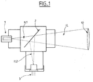
- Figure1 represents a conventional arrangement at a receiver end of a light beam carrying an optical signal.
- receiveriver in this description refers to any apparatus that receives an optical signal, irrespective of its function at each end of a transmission link. Therefore, transmitters that could receive an optical signal, such as a return signal, for whatever reason are also to be understood to fall within the scope of the term “receiver” for the purpose of this description.
- a splitter is placed on the path of the light beam that lets through a main portion of the incoming light beam and reflects a smaller portion thereof into a quad cells device so as to detect the position of the incoming light beam.
- the receiver 1 usually comprises a telescope arrangement, however in the figure only a single lens 12 is shown for the sake of simplicity. Nevertheless, the receiver may also comprise any optical scheme such as for example, refractive, reflective or catadioptric, known by skilled persons in the related the art.
- the converging incoming light beam IL encounters the splitter plate 2 that, by means of a proper coating of its surfaces, allows the major part of the signal IL1 to pass through and continue to be focalized on the main receiver device 1 which could be for example of the type using avalanche photodiodes (APD).
- APD avalanche photodiodes
- the splitter plate 2 reflects, preferably at 90°, a certain part of the signal IL2 to a quad cells device 3.
- the reflected portion IL2 is typically only in the range of 5-10% of the incoming beam IL so as to reduce the attenuation for the main receiver device 1 to the minimum value possible.
- the four photodiodes incorporated in the quad cell device would then give different values of voltages generated at their respective outputs and these differential values can be amplified and used for determining the deviation of the incoming light IL and correcting the position of the receiver 1 by actuating certain driving means for performing the desired correction of the position as will be described in below.
- the incoming light is modulated, for instance, by an On-Off Keying (OOK) signal.
- OOK On-Off Keying
- the frequency of the light carrying information is in the range of Mbit/s up to Gbit/s according the to the requirements of each particular transmission scheme.
- the quad cells device 3 is shown in conjunction to the rest of the circuitry necessary for detecting deviation and performing the correction of the receiver's position.
- the four quadrants of the quad cells device 3 are generated by respective photodiodes shown by references N, S, E, W standing for north, south, east and west respectively.
- Each of these four quadrants represent a value relative to the deviation of the incoming light expressed in terms of voltages at the output of the photodiodes, which will be referred to also as differential values.
- the output of the quad cells device 3, containing the four quadrant values, is fed into a low-noise amplifier 4 which is a conventional device in order to amplify the signals with a minimum the effect on the noise.
- a low-noise amplifier 4 which is a conventional device in order to amplify the signals with a minimum the effect on the noise.
- the four quadrant values are fed into a high-pass filter 5.
- the filter 5 blocks all DC as well as all low frequency components of the optical signal and lets pass through, the higher frequencies which contain the useful information on the optical signal.
- the range of frequencies to be blocked by the filter can be determined according to the requirements of each particular application.
- a preferred range comprises all frequency below about 1 kHz for blocking the daylight effect, and below or up to about 1MHz if it is desired to block interference from fluorescent lamps as well. All frequencies above these values are therefore allowed to pass through the filter.
- the output of the filter 5 is fed into a stage shown in the figure by reference numeral 6 comprising a set of amplifiers and a set of envelop detectors for the four quadrants of the optical signal, namely N, S, E, W.
- the operation of the amplifiers and the envelop detectors are known in the related art and thus for the sake of simplicity a detailed description thereof is considered not necessary.
- the four amplification chains within this stage are adapted to operate with AC components from a range of a few kHz up to the upper cut-off limit voltage of the diodes.
- the output of the amplifiers comprising four amplified differential values is fed into an automatic gain control (AGC) device 7 as shown by arrow 61.
- AGC automatic gain control
- the automatic gain control device 7 Based on the value received at the input, the automatic gain control device 7 generates a response signal 71 containing information relative to the correction of the position of the receiver 1. This is done by feeding from the amplifier stage 6, the appropriate correction information signals 62 and 63 into driver devices 8 and 9 respectively as shown in figure 2. In this example these signals contain correction information for E-W components represented by arrow 62 and N-S component represented by arrow 63. However other combinations may be used without altering the scope of the present invention.
- drivers 8 and 9 trigger respective actuator mechanisms 10 and 11 which move the receiver 1 in the desired directions in order to align the receiver 1 with the incoming light IL (IL1).
- a positive input voltage in the drivers 8 and 9 could cause the drivers to move the respective actuator 10 and 11 in a first direction by means of any known mechanism such as for example steering mirrors, gimbals, etc.; and a negative input voltage in the drivers would cause them to move the respective actuator in a second direction opposite to the first direction. A zero voltage would cause no movement in the actuators.
Landscapes
- Physics & Mathematics (AREA)
- Electromagnetism (AREA)
- Engineering & Computer Science (AREA)
- Computer Networks & Wireless Communication (AREA)
- Signal Processing (AREA)
- Optical Communication System (AREA)
Abstract
Description
- receiving an incoming light beam carrying an optical signal by a receiver;
- moving said receiver in different directions in response to a position correction signal so as to align said receiver with the incoming light beam;
- receiving a sample of said incoming light beam by a quad cells device and outputting from said quad cells device preferably four voltage value components of the received signal; characterized by the further steps of:
- blocking DC components as well as frequency components lower than a predetermined value from the optical signals on each one of the said preferably four output components of the quad cells device by means of a high pass filter connected at the output of said quad cells device, and using the output of the filter for determining a position of the incoming light with respect to the receiver.
Claims (9)
- System for eliminating external light interference effects in an active tracking equipment for free space optics communication, said system comprising a receiver (1) for receiving an incoming light beam (IL; IL1) carrying an optical signal, said receiver being moveable in different directions in response to a position correction signal so as to align said receiver (1) with the incoming light beam (IL; IL1), the system further comprising a quad cells device (3) for receiving a sample of said incoming light beam and outputting voltage value components voltage value components, preferably four, of the received signal, characterized in that said quad cells device (3) is connected to a high pass filter (5) adapted for blocking DC components as well as frequency components lower than a predetermined value from the signals on each one of the, preferably four, output components of the quad cells device (3), the output of the filter (5) being used for determining a position of the incoming light (IL; IL1) with respect to the receiver (1).
- A system according to claim 1 wherein said predetermined frequency value is below about 1 kHz for blocking daylight interference effects or below about 1MHz for blocking fluorescent lamps interference effects.
- A system according to claim 1 wherein said high pass filter (5) is connected to a set of amplifiers for amplifying the filtered signals, said amplifiers being in turn connected to an automatic gain control loop (7) adapted for being driven by a voltage obtained from the sum of output signals of the four amplifiers, said sum being indicative of information relative to differential values of said four components light as a function of the relative position of the incoming light beam (IL; IL1) received by said quad cells device (3), whereby said automatic gain control loop (7) generates a control signal (71) on the basis of the sum of the amplified signals received.
- A system according to claim 3 wherein said sum of the four amplifiers outputs is equal to zero when the incoming light beam is received at the center of the quad cells device.
- A system according to claim 3 or 4 wherein the signals from the output of the amplifiers are fed to a set of drivers for driving a set of movement actuators adapted for moving said receiver in a desired direction as a response to a control signal produced by the automatic gain control loop.
- A method for eliminating external light interference effects in an active tracking equipment for free space optics communication, said method comprising the steps of:receiving an incoming light beam (lL; IL1) carrying an optical signal by a receiver (1);moving said receiver (1) in different directions in response to a position correction signal so as to align said receiver (1) with the incoming light beam (IL; IL1);receiving a sample (IL2) of said incoming light beam by a quad cells device (3) and outputting from said quad cells device (3) voltage value components, preferably four, of the received signal; characterized by the further steps of:blocking DC components as well as frequency components lower than a predetermined value from the optical signals on each one of the preferably four output components of the quad cells device (3) by means of a high pass filter (5) connected at the output of said quad cells device (3), and using the output of the filter (5) for determining a position of the incoming light (IL; IL1) with respect to the receiver (1).
- A method according to claim 6 wherein said predetermined frequency value is below about 1 kHz for blocking daylight interference effects or below about 1 MHz for blocking fluorescent lamps interference effects.
- A method according to claim 6 wherein the filtered signals are amplified by a set of amplifiers, the resulting amplified signals being then summed (61) and fed to an automatic gain control loop (7), said sum (61) being indicative of information relative to differential values of said four components light as a function of the relative position of the incoming light beam (IL2) received by said quad cells device whereby said automatic gain control loop (7) generates a control signal (71) on the basis of the sum (61) of the amplified signals received.
- A method according to claim 8 wherein said control signal produced by the automatic gain control loop (7) is fed, through said amplifiers to a set of drivers (8; 9), and said drivers drive a set of movement actuators (10; 11) that move said receiver (1) in a desired direction as a response to said control signal (71).
Priority Applications (4)
| Application Number | Priority Date | Filing Date | Title |
|---|---|---|---|
| AT03291878T ATE414357T1 (en) | 2003-07-29 | 2003-07-29 | METHOD AND DEVICE FOR DELETING AN EXTERNAL INTERFACE EFFECT DURING ACTIVE TRACKING FOR OPTICAL FREE SPACE COMMUNICATION |
| EP03291878A EP1503526B1 (en) | 2003-07-29 | 2003-07-29 | System and method for eliminating effect of external interference on active tracking for free space optics communication |
| DE60324670T DE60324670D1 (en) | 2003-07-29 | 2003-07-29 | Method and apparatus for erasing an external interface effect in the active tracking track for a free-space optical communication |
| US10/900,154 US20050025492A1 (en) | 2003-07-29 | 2004-07-28 | System and method for eliminating effect of external interference on active tracking for free space optics communication |
Applications Claiming Priority (1)
| Application Number | Priority Date | Filing Date | Title |
|---|---|---|---|
| EP03291878A EP1503526B1 (en) | 2003-07-29 | 2003-07-29 | System and method for eliminating effect of external interference on active tracking for free space optics communication |
Publications (2)
| Publication Number | Publication Date |
|---|---|
| EP1503526A1 true EP1503526A1 (en) | 2005-02-02 |
| EP1503526B1 EP1503526B1 (en) | 2008-11-12 |
Family
ID=33522462
Family Applications (1)
| Application Number | Title | Priority Date | Filing Date |
|---|---|---|---|
| EP03291878A Expired - Lifetime EP1503526B1 (en) | 2003-07-29 | 2003-07-29 | System and method for eliminating effect of external interference on active tracking for free space optics communication |
Country Status (4)
| Country | Link |
|---|---|
| US (1) | US20050025492A1 (en) |
| EP (1) | EP1503526B1 (en) |
| AT (1) | ATE414357T1 (en) |
| DE (1) | DE60324670D1 (en) |
Cited By (1)
| Publication number | Priority date | Publication date | Assignee | Title |
|---|---|---|---|---|
| CN106921444A (en) * | 2015-12-28 | 2017-07-04 | 镇江高科信息科技有限公司 | A kind of wire optical communication system |
Families Citing this family (4)
| Publication number | Priority date | Publication date | Assignee | Title |
|---|---|---|---|---|
| US7646986B2 (en) * | 2006-04-27 | 2010-01-12 | Panasonic Corporation | Optical receiving device and optical receiving method |
| US7941051B2 (en) * | 2006-07-21 | 2011-05-10 | Konica Minolta Opto, Inc. | Laser optical device and control method of actuator |
| FR2934383B1 (en) * | 2008-07-24 | 2010-09-10 | Astrium Sas | OPTICAL COMMUNICATION TERMINAL WITH SINGLE LOOP SECURED POINTING. |
| GB2600437A (en) * | 2020-10-28 | 2022-05-04 | Airbus Sas | Free space optical receiver |
Citations (4)
| Publication number | Priority date | Publication date | Assignee | Title |
|---|---|---|---|---|
| US3504182A (en) * | 1966-10-14 | 1970-03-31 | North American Rockwell | Optical communication system |
| US20020154364A1 (en) * | 1999-07-08 | 2002-10-24 | Green Alan Edward | Signalling system |
| US6483621B1 (en) * | 2000-07-28 | 2002-11-19 | Terabeam Corporation | Method and apparatus for tone tracking in wireless optical communication systems |
| US6504634B1 (en) * | 1998-10-27 | 2003-01-07 | Air Fiber, Inc. | System and method for improved pointing accuracy |
Family Cites Families (5)
| Publication number | Priority date | Publication date | Assignee | Title |
|---|---|---|---|---|
| DE3328335C2 (en) * | 1983-08-05 | 1987-01-22 | Messerschmitt-Bölkow-Blohm GmbH, 8012 Ottobrunn | Remote data monitoring system |
| JPH0691558B2 (en) * | 1986-12-17 | 1994-11-14 | 株式会社日立製作所 | Digital signal transmission system |
| DE19824056A1 (en) * | 1998-05-29 | 1999-12-02 | Thomson Brandt Gmbh | Device for playing back or recording data or information |
| US6522440B1 (en) * | 1999-04-28 | 2003-02-18 | Trw Inc. | Inter-satellite optical link track sensor |
| US6768876B1 (en) * | 2000-07-28 | 2004-07-27 | Terabeam Corporation | Method and apparatus for tracking an optical communications system |
-
2003
- 2003-07-29 AT AT03291878T patent/ATE414357T1/en not_active IP Right Cessation
- 2003-07-29 DE DE60324670T patent/DE60324670D1/en not_active Expired - Lifetime
- 2003-07-29 EP EP03291878A patent/EP1503526B1/en not_active Expired - Lifetime
-
2004
- 2004-07-28 US US10/900,154 patent/US20050025492A1/en not_active Abandoned
Patent Citations (4)
| Publication number | Priority date | Publication date | Assignee | Title |
|---|---|---|---|---|
| US3504182A (en) * | 1966-10-14 | 1970-03-31 | North American Rockwell | Optical communication system |
| US6504634B1 (en) * | 1998-10-27 | 2003-01-07 | Air Fiber, Inc. | System and method for improved pointing accuracy |
| US20020154364A1 (en) * | 1999-07-08 | 2002-10-24 | Green Alan Edward | Signalling system |
| US6483621B1 (en) * | 2000-07-28 | 2002-11-19 | Terabeam Corporation | Method and apparatus for tone tracking in wireless optical communication systems |
Cited By (1)
| Publication number | Priority date | Publication date | Assignee | Title |
|---|---|---|---|---|
| CN106921444A (en) * | 2015-12-28 | 2017-07-04 | 镇江高科信息科技有限公司 | A kind of wire optical communication system |
Also Published As
| Publication number | Publication date |
|---|---|
| US20050025492A1 (en) | 2005-02-03 |
| DE60324670D1 (en) | 2008-12-24 |
| EP1503526B1 (en) | 2008-11-12 |
| ATE414357T1 (en) | 2008-11-15 |
Similar Documents
| Publication | Publication Date | Title |
|---|---|---|
| US20020131121A1 (en) | Transceiver, system, and method for free-space optical communication and tracking | |
| EP0653852B1 (en) | Free space optical communication system | |
| US6122084A (en) | High dynamic range free-space optical communication receiver | |
| US7406263B2 (en) | Combined wavefront sensor and data detector for a free space optical communications system with adaptive optics | |
| JP2009504110A (en) | Acquisition, indication, and tracking architecture for laser communications | |
| US12519542B2 (en) | Feedforward motion compensation for FSOC terminals | |
| CN1348265A (en) | Method and apparatus for calibrating telescope in free space optical communication system | |
| US6522440B1 (en) | Inter-satellite optical link track sensor | |
| EP1503526B1 (en) | System and method for eliminating effect of external interference on active tracking for free space optics communication | |
| WO2022072493A1 (en) | Determining pointing accuracy using optical fiber bundle | |
| AU658919B2 (en) | Optical communications systems | |
| US5638162A (en) | Optical signal enhancement system | |
| US6674974B1 (en) | Method and apparatus for tracking in an optical communications system | |
| US6768876B1 (en) | Method and apparatus for tracking an optical communications system | |
| EP0047779B1 (en) | Apparatus for nighttime and low visibility alignment of communicators | |
| AU2019408409A1 (en) | Ground station for analysing an optical data communication beam emanating from a satellite | |
| US6426494B1 (en) | Optical signal detector and optical signal detecting method | |
| JP3206993B2 (en) | Bidirectional optical space transmission equipment | |
| RU2223604C1 (en) | Wireless optical communication system | |
| US7308203B1 (en) | Free space optical data link for aircraft | |
| KR100374886B1 (en) | System for immunizing optical noise in an optical wireless system | |
| US12320697B1 (en) | Beam alignment system | |
| Grinch et al. | Laser system for cooperative pointing and tracking of moving terminals over long distance. | |
| CN121791961A (en) | Divergence angle-variable laser communication terminal | |
| White et al. | Demonstration of free-space optical communication link incorporating a closed-loop tracking system for mobile platforms |
Legal Events
| Date | Code | Title | Description |
|---|---|---|---|
| PUAI | Public reference made under article 153(3) epc to a published international application that has entered the european phase |
Free format text: ORIGINAL CODE: 0009012 |
|
| AK | Designated contracting states |
Kind code of ref document: A1 Designated state(s): AT BE BG CH CY CZ DE DK EE ES FI FR GB GR HU IE IT LI LU MC NL PT RO SE SI SK TR |
|
| AX | Request for extension of the european patent |
Extension state: AL LT LV MK |
|
| 17P | Request for examination filed |
Effective date: 20050802 |
|
| AKX | Designation fees paid |
Designated state(s): AT BE BG CH CY CZ DE DK EE ES FI FR GB GR HU IE IT LI LU MC NL PT RO SE SI SK TR |
|
| 17Q | First examination report despatched |
Effective date: 20060518 |
|
| RAP1 | Party data changed (applicant data changed or rights of an application transferred) |
Owner name: ALCATEL LUCENT |
|
| GRAP | Despatch of communication of intention to grant a patent |
Free format text: ORIGINAL CODE: EPIDOSNIGR1 |
|
| GRAS | Grant fee paid |
Free format text: ORIGINAL CODE: EPIDOSNIGR3 |
|
| GRAA | (expected) grant |
Free format text: ORIGINAL CODE: 0009210 |
|
| AK | Designated contracting states |
Kind code of ref document: B1 Designated state(s): AT BE BG CH CY CZ DE DK EE ES FI FR GB GR HU IE IT LI LU MC NL PT RO SE SI SK TR |
|
| REG | Reference to a national code |
Ref country code: GB Ref legal event code: FG4D |
|
| REG | Reference to a national code |
Ref country code: CH Ref legal event code: EP |
|
| REG | Reference to a national code |
Ref country code: IE Ref legal event code: FG4D |
|
| REF | Corresponds to: |
Ref document number: 60324670 Country of ref document: DE Date of ref document: 20081224 Kind code of ref document: P |
|
| PG25 | Lapsed in a contracting state [announced via postgrant information from national office to epo] |
Ref country code: ES Free format text: LAPSE BECAUSE OF FAILURE TO SUBMIT A TRANSLATION OF THE DESCRIPTION OR TO PAY THE FEE WITHIN THE PRESCRIBED TIME-LIMIT Effective date: 20090223 Ref country code: AT Free format text: LAPSE BECAUSE OF FAILURE TO SUBMIT A TRANSLATION OF THE DESCRIPTION OR TO PAY THE FEE WITHIN THE PRESCRIBED TIME-LIMIT Effective date: 20081112 |
|
| NLV1 | Nl: lapsed or annulled due to failure to fulfill the requirements of art. 29p and 29m of the patents act | ||
| PG25 | Lapsed in a contracting state [announced via postgrant information from national office to epo] |
Ref country code: NL Free format text: LAPSE BECAUSE OF FAILURE TO SUBMIT A TRANSLATION OF THE DESCRIPTION OR TO PAY THE FEE WITHIN THE PRESCRIBED TIME-LIMIT Effective date: 20081112 Ref country code: FI Free format text: LAPSE BECAUSE OF FAILURE TO SUBMIT A TRANSLATION OF THE DESCRIPTION OR TO PAY THE FEE WITHIN THE PRESCRIBED TIME-LIMIT Effective date: 20081112 Ref country code: SI Free format text: LAPSE BECAUSE OF FAILURE TO SUBMIT A TRANSLATION OF THE DESCRIPTION OR TO PAY THE FEE WITHIN THE PRESCRIBED TIME-LIMIT Effective date: 20081112 |
|
| PG25 | Lapsed in a contracting state [announced via postgrant information from national office to epo] |
Ref country code: BG Free format text: LAPSE BECAUSE OF FAILURE TO SUBMIT A TRANSLATION OF THE DESCRIPTION OR TO PAY THE FEE WITHIN THE PRESCRIBED TIME-LIMIT Effective date: 20090212 Ref country code: DK Free format text: LAPSE BECAUSE OF FAILURE TO SUBMIT A TRANSLATION OF THE DESCRIPTION OR TO PAY THE FEE WITHIN THE PRESCRIBED TIME-LIMIT Effective date: 20081112 Ref country code: BE Free format text: LAPSE BECAUSE OF FAILURE TO SUBMIT A TRANSLATION OF THE DESCRIPTION OR TO PAY THE FEE WITHIN THE PRESCRIBED TIME-LIMIT Effective date: 20081112 Ref country code: RO Free format text: LAPSE BECAUSE OF FAILURE TO SUBMIT A TRANSLATION OF THE DESCRIPTION OR TO PAY THE FEE WITHIN THE PRESCRIBED TIME-LIMIT Effective date: 20081112 Ref country code: EE Free format text: LAPSE BECAUSE OF FAILURE TO SUBMIT A TRANSLATION OF THE DESCRIPTION OR TO PAY THE FEE WITHIN THE PRESCRIBED TIME-LIMIT Effective date: 20081112 |
|
| PG25 | Lapsed in a contracting state [announced via postgrant information from national office to epo] |
Ref country code: CZ Free format text: LAPSE BECAUSE OF FAILURE TO SUBMIT A TRANSLATION OF THE DESCRIPTION OR TO PAY THE FEE WITHIN THE PRESCRIBED TIME-LIMIT Effective date: 20081112 Ref country code: PT Free format text: LAPSE BECAUSE OF FAILURE TO SUBMIT A TRANSLATION OF THE DESCRIPTION OR TO PAY THE FEE WITHIN THE PRESCRIBED TIME-LIMIT Effective date: 20090413 Ref country code: SE Free format text: LAPSE BECAUSE OF FAILURE TO SUBMIT A TRANSLATION OF THE DESCRIPTION OR TO PAY THE FEE WITHIN THE PRESCRIBED TIME-LIMIT Effective date: 20090212 |
|
| PLBE | No opposition filed within time limit |
Free format text: ORIGINAL CODE: 0009261 |
|
| STAA | Information on the status of an ep patent application or granted ep patent |
Free format text: STATUS: NO OPPOSITION FILED WITHIN TIME LIMIT |
|
| PG25 | Lapsed in a contracting state [announced via postgrant information from national office to epo] |
Ref country code: SK Free format text: LAPSE BECAUSE OF FAILURE TO SUBMIT A TRANSLATION OF THE DESCRIPTION OR TO PAY THE FEE WITHIN THE PRESCRIBED TIME-LIMIT Effective date: 20081112 |
|
| 26N | No opposition filed |
Effective date: 20090813 |
|
| PG25 | Lapsed in a contracting state [announced via postgrant information from national office to epo] |
Ref country code: MC Free format text: LAPSE BECAUSE OF NON-PAYMENT OF DUE FEES Effective date: 20090731 |
|
| REG | Reference to a national code |
Ref country code: CH Ref legal event code: PL |
|
| PG25 | Lapsed in a contracting state [announced via postgrant information from national office to epo] |
Ref country code: LI Free format text: LAPSE BECAUSE OF NON-PAYMENT OF DUE FEES Effective date: 20090731 Ref country code: CH Free format text: LAPSE BECAUSE OF NON-PAYMENT OF DUE FEES Effective date: 20090731 |
|
| PG25 | Lapsed in a contracting state [announced via postgrant information from national office to epo] |
Ref country code: IE Free format text: LAPSE BECAUSE OF NON-PAYMENT OF DUE FEES Effective date: 20090729 |
|
| PG25 | Lapsed in a contracting state [announced via postgrant information from national office to epo] |
Ref country code: GR Free format text: LAPSE BECAUSE OF FAILURE TO SUBMIT A TRANSLATION OF THE DESCRIPTION OR TO PAY THE FEE WITHIN THE PRESCRIBED TIME-LIMIT Effective date: 20090213 |
|
| PG25 | Lapsed in a contracting state [announced via postgrant information from national office to epo] |
Ref country code: IT Free format text: LAPSE BECAUSE OF FAILURE TO SUBMIT A TRANSLATION OF THE DESCRIPTION OR TO PAY THE FEE WITHIN THE PRESCRIBED TIME-LIMIT Effective date: 20081112 |
|
| PG25 | Lapsed in a contracting state [announced via postgrant information from national office to epo] |
Ref country code: LU Free format text: LAPSE BECAUSE OF NON-PAYMENT OF DUE FEES Effective date: 20090729 |
|
| PG25 | Lapsed in a contracting state [announced via postgrant information from national office to epo] |
Ref country code: HU Free format text: LAPSE BECAUSE OF FAILURE TO SUBMIT A TRANSLATION OF THE DESCRIPTION OR TO PAY THE FEE WITHIN THE PRESCRIBED TIME-LIMIT Effective date: 20090513 |
|
| PG25 | Lapsed in a contracting state [announced via postgrant information from national office to epo] |
Ref country code: TR Free format text: LAPSE BECAUSE OF FAILURE TO SUBMIT A TRANSLATION OF THE DESCRIPTION OR TO PAY THE FEE WITHIN THE PRESCRIBED TIME-LIMIT Effective date: 20081112 |
|
| PG25 | Lapsed in a contracting state [announced via postgrant information from national office to epo] |
Ref country code: CY Free format text: LAPSE BECAUSE OF FAILURE TO SUBMIT A TRANSLATION OF THE DESCRIPTION OR TO PAY THE FEE WITHIN THE PRESCRIBED TIME-LIMIT Effective date: 20081112 |
|
| REG | Reference to a national code |
Ref country code: FR Ref legal event code: GC Effective date: 20131018 |
|
| REG | Reference to a national code |
Ref country code: FR Ref legal event code: RG Effective date: 20141016 |
|
| REG | Reference to a national code |
Ref country code: FR Ref legal event code: PLFP Year of fee payment: 13 |
|
| REG | Reference to a national code |
Ref country code: FR Ref legal event code: CA Effective date: 20150521 |
|
| REG | Reference to a national code |
Ref country code: FR Ref legal event code: CA Effective date: 20150521 |
|
| PGFP | Annual fee paid to national office [announced via postgrant information from national office to epo] |
Ref country code: FR Payment date: 20150626 Year of fee payment: 13 |
|
| PGFP | Annual fee paid to national office [announced via postgrant information from national office to epo] |
Ref country code: DE Payment date: 20150721 Year of fee payment: 13 Ref country code: GB Payment date: 20150721 Year of fee payment: 13 |
|
| REG | Reference to a national code |
Ref country code: DE Ref legal event code: R119 Ref document number: 60324670 Country of ref document: DE |
|
| GBPC | Gb: european patent ceased through non-payment of renewal fee |
Effective date: 20160729 |
|
| PG25 | Lapsed in a contracting state [announced via postgrant information from national office to epo] |
Ref country code: FR Free format text: LAPSE BECAUSE OF NON-PAYMENT OF DUE FEES Effective date: 20160801 Ref country code: DE Free format text: LAPSE BECAUSE OF NON-PAYMENT OF DUE FEES Effective date: 20170201 |
|
| REG | Reference to a national code |
Ref country code: FR Ref legal event code: ST Effective date: 20170331 |
|
| PG25 | Lapsed in a contracting state [announced via postgrant information from national office to epo] |
Ref country code: GB Free format text: LAPSE BECAUSE OF NON-PAYMENT OF DUE FEES Effective date: 20160729 |