EP1503215A1 - Tragring für einen magnetischen Drehgeber - Google Patents
Tragring für einen magnetischen Drehgeber Download PDFInfo
- Publication number
- EP1503215A1 EP1503215A1 EP04090179A EP04090179A EP1503215A1 EP 1503215 A1 EP1503215 A1 EP 1503215A1 EP 04090179 A EP04090179 A EP 04090179A EP 04090179 A EP04090179 A EP 04090179A EP 1503215 A1 EP1503215 A1 EP 1503215A1
- Authority
- EP
- European Patent Office
- Prior art keywords
- magnetic tape
- support ring
- ring according
- magnetic
- cover strip
- Prior art date
- Legal status (The legal status is an assumption and is not a legal conclusion. Google has not performed a legal analysis and makes no representation as to the accuracy of the status listed.)
- Granted
Links
- 239000000853 adhesive Substances 0.000 claims abstract description 8
- 230000001070 adhesive effect Effects 0.000 claims abstract description 8
- 230000002093 peripheral effect Effects 0.000 claims description 4
- 239000012790 adhesive layer Substances 0.000 description 3
- 230000005415 magnetization Effects 0.000 description 3
- 239000002390 adhesive tape Substances 0.000 description 1
- 230000001419 dependent effect Effects 0.000 description 1
- 238000009434 installation Methods 0.000 description 1
- 230000000873 masking effect Effects 0.000 description 1
- 238000007789 sealing Methods 0.000 description 1
- 239000003566 sealing material Substances 0.000 description 1
- 230000035939 shock Effects 0.000 description 1
- 239000006228 supernatant Substances 0.000 description 1
- 238000004804 winding Methods 0.000 description 1
Images
Classifications
-
- G—PHYSICS
- G01—MEASURING; TESTING
- G01P—MEASURING LINEAR OR ANGULAR SPEED, ACCELERATION, DECELERATION, OR SHOCK; INDICATING PRESENCE, ABSENCE, OR DIRECTION, OF MOVEMENT
- G01P3/00—Measuring linear or angular speed; Measuring differences of linear or angular speeds
- G01P3/42—Devices characterised by the use of electric or magnetic means
- G01P3/44—Devices characterised by the use of electric or magnetic means for measuring angular speed
- G01P3/48—Devices characterised by the use of electric or magnetic means for measuring angular speed by measuring frequency of generated current or voltage
- G01P3/481—Devices characterised by the use of electric or magnetic means for measuring angular speed by measuring frequency of generated current or voltage of pulse signals
- G01P3/487—Devices characterised by the use of electric or magnetic means for measuring angular speed by measuring frequency of generated current or voltage of pulse signals delivered by rotating magnets
-
- B—PERFORMING OPERATIONS; TRANSPORTING
- B29—WORKING OF PLASTICS; WORKING OF SUBSTANCES IN A PLASTIC STATE IN GENERAL
- B29C—SHAPING OR JOINING OF PLASTICS; SHAPING OF MATERIAL IN A PLASTIC STATE, NOT OTHERWISE PROVIDED FOR; AFTER-TREATMENT OF THE SHAPED PRODUCTS, e.g. REPAIRING
- B29C66/00—General aspects of processes or apparatus for joining preformed parts
- B29C66/01—General aspects dealing with the joint area or with the area to be joined
- B29C66/32—Measures for keeping the burr form under control; Avoiding burr formation; Shaping the burr
- B29C66/322—Providing cavities in the joined article to collect the burr
-
- G—PHYSICS
- G01—MEASURING; TESTING
- G01D—MEASURING NOT SPECIALLY ADAPTED FOR A SPECIFIC VARIABLE; ARRANGEMENTS FOR MEASURING TWO OR MORE VARIABLES NOT COVERED IN A SINGLE OTHER SUBCLASS; TARIFF METERING APPARATUS; MEASURING OR TESTING NOT OTHERWISE PROVIDED FOR
- G01D5/00—Mechanical means for transferring the output of a sensing member; Means for converting the output of a sensing member to another variable where the form or nature of the sensing member does not constrain the means for converting; Transducers not specially adapted for a specific variable
- G01D5/12—Mechanical means for transferring the output of a sensing member; Means for converting the output of a sensing member to another variable where the form or nature of the sensing member does not constrain the means for converting; Transducers not specially adapted for a specific variable using electric or magnetic means
- G01D5/14—Mechanical means for transferring the output of a sensing member; Means for converting the output of a sensing member to another variable where the form or nature of the sensing member does not constrain the means for converting; Transducers not specially adapted for a specific variable using electric or magnetic means influencing the magnitude of a current or voltage
-
- B—PERFORMING OPERATIONS; TRANSPORTING
- B29—WORKING OF PLASTICS; WORKING OF SUBSTANCES IN A PLASTIC STATE IN GENERAL
- B29C—SHAPING OR JOINING OF PLASTICS; SHAPING OF MATERIAL IN A PLASTIC STATE, NOT OTHERWISE PROVIDED FOR; AFTER-TREATMENT OF THE SHAPED PRODUCTS, e.g. REPAIRING
- B29C65/00—Joining or sealing of preformed parts, e.g. welding of plastics materials; Apparatus therefor
- B29C65/02—Joining or sealing of preformed parts, e.g. welding of plastics materials; Apparatus therefor by heating, with or without pressure
Definitions
- the invention relates to a support ring for a magnetic encoder with at least one connected by an adhesive to the circumference of the ring, alternately north-south-polarized magnetic tape.
- Such a support ring is known, on the one side of an annular Magnetic tape pushed the example of DE 198 56 493 C2 known type is, whose end position is assigned by one of an edge of the magnetic tape Stop collar of the support ring is determined.
- the known support ring can not be fully satisfied insofar as when pushing of the magnetic tape on the support ring the leading edge of the magnetic tape one more or less large amount of the adhesive is pushing and no guarantee for the Forming a uniform adhesive layer between the magnetic tape and the Support ring is given.
- the invention is based on the object, a support ring of the considered To change the type so that the type of installation does not affect the Uniformity of the adhesive layer brings with it and that in addition by both Stops of the magnetic tape associated attacks a safer positioning of the Magnetic tape is achieved.
- the support ring with at least one serving for receiving the magnetic tape multi-stage groove whose bottom step forms a collecting channel for excess adhesive and their level adjoining the lowest stage a guide channel for the Magnetic tape shapes.
- the advantage of the support ring according to the invention consists u. a. in that with him that Magnetic tape is not tangential during assembly, but normal to Adhesive layer is moved and that the mutual guidance of the magnetic tape in a groove ensures a perfect fit of the magnetic tape.
- the depth of the guide channel forming stage is smaller than the height of the magnetic tape, the outer surface is offset from the peripheral surface of the support ring to the center of the support ring. Because the magnetic tape does not protrude beyond the circumference of the support ring, it is not only protected against damage, but also makes it special Simply seal in addition to the environment by a masking tape.
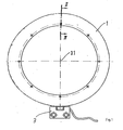
- Fig. 1, 1 is a on a large-sized hollow shaft in the manner of a Screw flange attachable support ring, the im'Bereich its circumference - as shown in FIG. 2 recognizable - is provided with a magnetic tape 2, which alternately north-south-polarized is magnetized.
- the magnetic tape 2 can be used as a closed ring or as to the Support ring 1 laying strip to be formed, the ends joined together in shock are.
- the magnetic pattern is scanned by a scanning head 3, the magnetic field sensitive Has sensors.
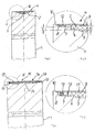
- the lowest, central level 5 represents one Collecting channel for an adhesive, with which the magnetic tape 2 at the bottom of the lowest level 5 subsequent level 6 is glued.
- the side walls of the step 6 are used for accurate positioning of the magnetic tape 2, the outer surface of the 9th is offset from the peripheral surface 10 of the support ring 1 to the center 11 thereof.
- the depth T of a guide channel for the magnetic tape 2 forming step 6 is smaller as the height H of the magnetic tape 2, so that the magnetic tape 2 over the bottom of the Stage 7 protrudes. The supernatant is important in cases where the magnetic tape 2 only in the glued state is magnetized.
- stage 8 serves for Recording a cover strip 12, which is designed as a self-adhesive tape and under Temperature and traction over the circumference of the support ring 1 and the Outside surface 9 of the magnetic tape 2 is wound, wherein the space between the bottom of the step 7 and the underside of the cover strip 12 for receiving a Sealing material or - as shown in Figures 4 and 5 - of O-rings 13th can be used.
- the support ring 1 can this for example, in a medium such as oil, which under a pressure of z. B. 10 bar and has a temperature of 90 and more degrees.
- the support ring 1 in the area its circumference is equipped with a kind of twin groove, consisting of two by one Ring web 14 separated from each other multi-stage grooves 15 and 16, whose Structure largely corresponds to the structure of the groove 4.
- the ring land 14 separates two here magnetizable bands 17, 18, of which the band 17, for example, a incremental and the band 18 carries absolute information. Through the ring land 14 In this case, a magnetic crosstalk of the magnetic tapes 17, 18 is prevented. Also in this embodiment, the magnetic tapes 17, 18 through a cover strip 12th protected against external influences, wherein when winding the cover strip on the Support ring 1, the O-rings 13 are pressurized to a perfect Achieve sealing.
Landscapes
- Physics & Mathematics (AREA)
- General Physics & Mathematics (AREA)
- Engineering & Computer Science (AREA)
- Mechanical Engineering (AREA)
- Transmission And Conversion Of Sensor Element Output (AREA)
Abstract
Description
- Fig. 1
- den grundsätzlichen Aufbau eines Drehgebers mit einem Tragring für ein Magnetband
- Fig. 2
- einen Schnitt längs der Linie II - II in Fig. 1
- Fig. 3
- eine Einzelheit III in Fig. 2
- Fig. 4
- einen dem Schnitt gemäß Fig. 2 entsprechenden Schnitt durch eine modifizierte Ausführungsform und
- Fig. 5
- eine Einzelheit V in Fig. 4.
Claims (9)
- Tragring für einen magnetischen Drehgeber mit mindestens einem durch einen Kleber mit dem Umfang des Ringes verbundenen, abwechselnd nord-süd-gepolten Magnetband, dadurch gekennzeichnet, dass er mit mindestens einer zur Aufnahme des Magnetbandes (2; 17, 18) dienenden mehrstufigen Nut (4; 15, 16) versehen ist, deren unterste Stufe (5) eine Sammelrinne für überschüssigen Kleber bildet und deren sich an die unterste Stufe (5) anschließende Stufe (6) einen Führungskanal für das Magnetband (2; 17, 18) formt.
- Tragring nach Anspruch 1, dadurch gekennzeichnet, dass die Tiefe (T) der den Führungskanal bildenden Stufe (6) kleiner als die Höhe (H) des Magnetbandes (2; 17, 18) ist, dessen Außenfläche (9) gegenüber der Umfangsfläche (10) des Tragringes (1) zum Zentrum (11) des Tragringes (1) versetzt ist.
- Tragring nach Anspruch 1 oder 2, dadurch gekennzeichnet, dass das Magnetband (2; 17, 18) durch ein Abdeckband (12) gegen äußere Einflüsse geschützt ist.
- Tragring nach Anspruch 3, dadurch gekennzeichnet, dass sich an die den Führungskanal für das Magnetband (2; 17, 18) bildende Stufe (6) zwei weitere Stufen (7, 8) anschließen, von denen die äußere zur Aufnahme des Abdeckbandes (12) dient.
- Tragring nach Anspruch 4, dadurch gekennzeichnet, dass der Boden der zur Aufnahme des Abdeckbandes (12) dienenden Stufe (8) mit der Außenfläche (9) des Magnetbandes (2; 17, 18) fluchtet.
- Tragring nach Anspruch 4 oder 5, dadurch gekennzeichnet, dass der Zwischenraum zwischen der auf die zur Aufnahme des Magnetbandes (2; 17, 18) dienenden Stufe (6) folgenden Stufe (7) und der zur Aufnahme des Abdeckbandes (12) dienenden Stufe (8) zur Aufnahme einer Dichtung nutzbar ist.
- Tragring nach Anspruch 6, dadurch gekennzeichnet, dass die Dichtung von O-Ringen (13) gebildet wird.
- Tragring nach einem der Ansprüche 1 bis 7, dadurch gekennzeichnet, dass er zwei nebeneinander angeordnete, mehrstufige Nuten (17, 18) aufweist.
- Tragring nach Anspruch 8, dadurch gekennzeichnet, dass zwischen den benachbarten Nuten (17, 18) ein Ringsteg (14) angeordnet ist, dessen Umfangsfläche mit dem Boden der zur Aufnahme des Abdeckbandes (12) dienenden Stufe (8) fluchtet.
Applications Claiming Priority (2)
| Application Number | Priority Date | Filing Date | Title |
|---|---|---|---|
| DE10334735A DE10334735A1 (de) | 2003-07-26 | 2003-07-26 | Tragring für einen magnetischen Drehgeber |
| DE10334735 | 2003-07-26 |
Publications (2)
| Publication Number | Publication Date |
|---|---|
| EP1503215A1 true EP1503215A1 (de) | 2005-02-02 |
| EP1503215B1 EP1503215B1 (de) | 2010-03-24 |
Family
ID=33521480
Family Applications (1)
| Application Number | Title | Priority Date | Filing Date |
|---|---|---|---|
| EP04090179A Expired - Lifetime EP1503215B1 (de) | 2003-07-26 | 2004-05-06 | Tragring für einen magnetischen Drehgeber |
Country Status (3)
| Country | Link |
|---|---|
| EP (1) | EP1503215B1 (de) |
| AT (1) | ATE462143T1 (de) |
| DE (2) | DE10334735A1 (de) |
Cited By (3)
| Publication number | Priority date | Publication date | Assignee | Title |
|---|---|---|---|---|
| WO2009033452A1 (de) * | 2007-09-11 | 2009-03-19 | Schaeffler Kg | Verfahren zum herstellen eines multipol-encoders |
| US8191399B2 (en) | 2005-12-16 | 2012-06-05 | Siemens Aktiengesellschaft | Monitoring device and monitoring method for a drive device |
| DE102011015886A1 (de) * | 2011-04-01 | 2012-10-04 | Carl Freudenberg Kg | Verfahren zur Herstellung eines magnetischen Encoderrings |
Families Citing this family (1)
| Publication number | Priority date | Publication date | Assignee | Title |
|---|---|---|---|---|
| DE102016108845A1 (de) | 2016-05-12 | 2017-11-16 | Stephan Wege | Gasinjektor für Reaktorbereiche |
Citations (4)
| Publication number | Priority date | Publication date | Assignee | Title |
|---|---|---|---|---|
| EP0390261A2 (de) * | 1989-03-28 | 1990-10-03 | Koninklijke Philips Electronics N.V. | Einrichtung zur Messung einer relativen Verlagerung |
| JPH03189127A (ja) * | 1989-12-19 | 1991-08-19 | Tokico Ltd | 接着式組立体 |
| DE19856493A1 (de) * | 1998-12-08 | 2000-06-29 | Freudenberg Carl Fa | Flächenhaftes Sensorelement |
| US6113276A (en) * | 1996-06-21 | 2000-09-05 | Rks S.A. | Slewing bearing with integral sensor |
Family Cites Families (3)
| Publication number | Priority date | Publication date | Assignee | Title |
|---|---|---|---|---|
| DE19611983C1 (de) * | 1996-03-26 | 1997-07-31 | Zeiss Carl Jena Gmbh | Bandförmiges, elastisch biegbares Maßband für Längen- oder Winkelmeßeinrichtungen |
| DE19912310B4 (de) * | 1999-03-19 | 2007-11-29 | Dr. Johannes Heidenhain Gmbh | Positionsmeßeinrichtung |
| DE19936536A1 (de) * | 1999-08-03 | 2001-02-08 | Heidenhain Gmbh Dr Johannes | Magnetische Maßverkörperung und Verfahren zur Herstellung einer magnetischen Maßverkörperung |
-
2003
- 2003-07-26 DE DE10334735A patent/DE10334735A1/de not_active Withdrawn
-
2004
- 2004-05-06 DE DE502004010930T patent/DE502004010930D1/de not_active Expired - Lifetime
- 2004-05-06 AT AT04090179T patent/ATE462143T1/de not_active IP Right Cessation
- 2004-05-06 EP EP04090179A patent/EP1503215B1/de not_active Expired - Lifetime
Patent Citations (4)
| Publication number | Priority date | Publication date | Assignee | Title |
|---|---|---|---|---|
| EP0390261A2 (de) * | 1989-03-28 | 1990-10-03 | Koninklijke Philips Electronics N.V. | Einrichtung zur Messung einer relativen Verlagerung |
| JPH03189127A (ja) * | 1989-12-19 | 1991-08-19 | Tokico Ltd | 接着式組立体 |
| US6113276A (en) * | 1996-06-21 | 2000-09-05 | Rks S.A. | Slewing bearing with integral sensor |
| DE19856493A1 (de) * | 1998-12-08 | 2000-06-29 | Freudenberg Carl Fa | Flächenhaftes Sensorelement |
Non-Patent Citations (1)
| Title |
|---|
| PATENT ABSTRACTS OF JAPAN vol. 015, no. 443 (M - 1178) 12 November 1991 (1991-11-12) * |
Cited By (3)
| Publication number | Priority date | Publication date | Assignee | Title |
|---|---|---|---|---|
| US8191399B2 (en) | 2005-12-16 | 2012-06-05 | Siemens Aktiengesellschaft | Monitoring device and monitoring method for a drive device |
| WO2009033452A1 (de) * | 2007-09-11 | 2009-03-19 | Schaeffler Kg | Verfahren zum herstellen eines multipol-encoders |
| DE102011015886A1 (de) * | 2011-04-01 | 2012-10-04 | Carl Freudenberg Kg | Verfahren zur Herstellung eines magnetischen Encoderrings |
Also Published As
| Publication number | Publication date |
|---|---|
| EP1503215B1 (de) | 2010-03-24 |
| ATE462143T1 (de) | 2010-04-15 |
| DE10334735A1 (de) | 2005-03-03 |
| DE502004010930D1 (de) | 2010-05-06 |
Similar Documents
| Publication | Publication Date | Title |
|---|---|---|
| DE10109320C2 (de) | Radialwellendichtring | |
| EP1512201B1 (de) | Kommutator für eine elektrische maschine | |
| DE102012205219A1 (de) | Vorrichtung zum Aufnehmen eines Pflanzentopfes | |
| DE60107549T2 (de) | Hochdruckdichtung | |
| DE102016100236A1 (de) | Drehmomentsensorvorrichtung für ein Kraftfahrzeug, elektrisches Lenksystem sowie Kraftfahrzeug | |
| DE19745802B4 (de) | Mehrwegeventilgehäuse aus spritzgegossenem Kunststoff mit integrierten Führungselementen | |
| DE19601964A1 (de) | Aufbau eines Lenkwinkelsensormuduls | |
| EP1503215A1 (de) | Tragring für einen magnetischen Drehgeber | |
| EP0631057B1 (de) | Dichtung für einen pneumatisch angetrieben Kolben | |
| DE3015258A1 (de) | Kolbenstellungsgeber | |
| DE19854100A1 (de) | Magnetspulenanordnung | |
| DE3221794C2 (de) | ||
| DE2546805C3 (de) | Dichtring für drehbare Körper, wie Wellen o.dgl. | |
| DE20311754U1 (de) | Tragring für einen magnetischen Drehgeber | |
| DE60111719T2 (de) | Winkelkodierer mit einem Kodierteil, das sich exakt auf einem Kreis mit der sich drehenden Welle bewegt | |
| DE102007043221A1 (de) | Verfahren zum Herstellen eines Multipol-Encoders | |
| DE3142617C2 (de) | ||
| EP2383755B1 (de) | Induktionsbauteil | |
| DE10049118C2 (de) | Flachdichtung | |
| DE2834253C2 (de) | Magnetischer Ständer, insbesondere Meßstander | |
| EP1076398A2 (de) | Motor | |
| DE3022070C2 (de) | Schirmkörper für bewickelte Kernschenkel von Transformatoren, Drosselspulen u.dgl. | |
| DE3329302C2 (de) | ||
| DE2241637A1 (de) | Anzeigevorrichtung mit rotierenden ringen | |
| DE102013202251A1 (de) | Radlagereinheit mit Innenring als Signalgeber |
Legal Events
| Date | Code | Title | Description |
|---|---|---|---|
| PUAI | Public reference made under article 153(3) epc to a published international application that has entered the european phase |
Free format text: ORIGINAL CODE: 0009012 |
|
| AK | Designated contracting states |
Kind code of ref document: A1 Designated state(s): AT BE BG CH CY CZ DE DK EE ES FI FR GB GR HU IE IT LI LU MC NL PL PT RO SE SI SK TR |
|
| AX | Request for extension of the european patent |
Extension state: AL HR LT LV MK |
|
| 17P | Request for examination filed |
Effective date: 20050608 |
|
| RAP1 | Party data changed (applicant data changed or rights of an application transferred) |
Owner name: HUEBNER ELEKTROMASCHINEN GMBH |
|
| AKX | Designation fees paid |
Designated state(s): AT BE BG CH CY CZ DE DK EE ES FI FR GB GR HU IE IT LI LU MC NL PL PT RO SE SI SK TR |
|
| RAP1 | Party data changed (applicant data changed or rights of an application transferred) |
Owner name: BAUMER HUEBNER GMBH |
|
| RIN1 | Information on inventor provided before grant (corrected) |
Inventor name: WILHELMY, LOTHAR Inventor name: HILLER, BERNHARD |
|
| GRAP | Despatch of communication of intention to grant a patent |
Free format text: ORIGINAL CODE: EPIDOSNIGR1 |
|
| GRAS | Grant fee paid |
Free format text: ORIGINAL CODE: EPIDOSNIGR3 |
|
| GRAA | (expected) grant |
Free format text: ORIGINAL CODE: 0009210 |
|
| AK | Designated contracting states |
Kind code of ref document: B1 Designated state(s): AT BE BG CH CY CZ DE DK EE ES FI FR GB GR HU IE IT LI LU MC NL PL PT RO SE SI SK TR |
|
| REG | Reference to a national code |
Ref country code: GB Ref legal event code: FG4D Free format text: NOT ENGLISH |
|
| REG | Reference to a national code |
Ref country code: CH Ref legal event code: EP Ref country code: CH Ref legal event code: NV Representative=s name: PATENTANWALTSBUERO JEAN HUNZIKER AG |
|
| REG | Reference to a national code |
Ref country code: IE Ref legal event code: FG4D |
|
| REF | Corresponds to: |
Ref document number: 502004010930 Country of ref document: DE Date of ref document: 20100506 Kind code of ref document: P |
|
| REG | Reference to a national code |
Ref country code: NL Ref legal event code: VDEP Effective date: 20100324 |
|
| PG25 | Lapsed in a contracting state [announced via postgrant information from national office to epo] |
Ref country code: FI Free format text: LAPSE BECAUSE OF FAILURE TO SUBMIT A TRANSLATION OF THE DESCRIPTION OR TO PAY THE FEE WITHIN THE PRESCRIBED TIME-LIMIT Effective date: 20100324 Ref country code: SI Free format text: LAPSE BECAUSE OF FAILURE TO SUBMIT A TRANSLATION OF THE DESCRIPTION OR TO PAY THE FEE WITHIN THE PRESCRIBED TIME-LIMIT Effective date: 20100324 Ref country code: PL Free format text: LAPSE BECAUSE OF FAILURE TO SUBMIT A TRANSLATION OF THE DESCRIPTION OR TO PAY THE FEE WITHIN THE PRESCRIBED TIME-LIMIT Effective date: 20100324 |
|
| REG | Reference to a national code |
Ref country code: IE Ref legal event code: FD4D |
|
| PG25 | Lapsed in a contracting state [announced via postgrant information from national office to epo] |
Ref country code: ES Free format text: LAPSE BECAUSE OF FAILURE TO SUBMIT A TRANSLATION OF THE DESCRIPTION OR TO PAY THE FEE WITHIN THE PRESCRIBED TIME-LIMIT Effective date: 20100705 Ref country code: GR Free format text: LAPSE BECAUSE OF FAILURE TO SUBMIT A TRANSLATION OF THE DESCRIPTION OR TO PAY THE FEE WITHIN THE PRESCRIBED TIME-LIMIT Effective date: 20100625 Ref country code: NL Free format text: LAPSE BECAUSE OF FAILURE TO SUBMIT A TRANSLATION OF THE DESCRIPTION OR TO PAY THE FEE WITHIN THE PRESCRIBED TIME-LIMIT Effective date: 20100324 Ref country code: RO Free format text: LAPSE BECAUSE OF FAILURE TO SUBMIT A TRANSLATION OF THE DESCRIPTION OR TO PAY THE FEE WITHIN THE PRESCRIBED TIME-LIMIT Effective date: 20100324 Ref country code: SE Free format text: LAPSE BECAUSE OF FAILURE TO SUBMIT A TRANSLATION OF THE DESCRIPTION OR TO PAY THE FEE WITHIN THE PRESCRIBED TIME-LIMIT Effective date: 20100324 Ref country code: EE Free format text: LAPSE BECAUSE OF FAILURE TO SUBMIT A TRANSLATION OF THE DESCRIPTION OR TO PAY THE FEE WITHIN THE PRESCRIBED TIME-LIMIT Effective date: 20100324 |
|
| BERE | Be: lapsed |
Owner name: BAUMER HUBNER G.M.B.H. Effective date: 20100531 |
|
| PG25 | Lapsed in a contracting state [announced via postgrant information from national office to epo] |
Ref country code: SK Free format text: LAPSE BECAUSE OF FAILURE TO SUBMIT A TRANSLATION OF THE DESCRIPTION OR TO PAY THE FEE WITHIN THE PRESCRIBED TIME-LIMIT Effective date: 20100324 Ref country code: BG Free format text: LAPSE BECAUSE OF FAILURE TO SUBMIT A TRANSLATION OF THE DESCRIPTION OR TO PAY THE FEE WITHIN THE PRESCRIBED TIME-LIMIT Effective date: 20100624 Ref country code: CZ Free format text: LAPSE BECAUSE OF FAILURE TO SUBMIT A TRANSLATION OF THE DESCRIPTION OR TO PAY THE FEE WITHIN THE PRESCRIBED TIME-LIMIT Effective date: 20100324 |
|
| PG25 | Lapsed in a contracting state [announced via postgrant information from national office to epo] |
Ref country code: MC Free format text: LAPSE BECAUSE OF NON-PAYMENT OF DUE FEES Effective date: 20100531 |
|
| PLBE | No opposition filed within time limit |
Free format text: ORIGINAL CODE: 0009261 |
|
| STAA | Information on the status of an ep patent application or granted ep patent |
Free format text: STATUS: NO OPPOSITION FILED WITHIN TIME LIMIT |
|
| PG25 | Lapsed in a contracting state [announced via postgrant information from national office to epo] |
Ref country code: IE Free format text: LAPSE BECAUSE OF FAILURE TO SUBMIT A TRANSLATION OF THE DESCRIPTION OR TO PAY THE FEE WITHIN THE PRESCRIBED TIME-LIMIT Effective date: 20100324 Ref country code: DK Free format text: LAPSE BECAUSE OF FAILURE TO SUBMIT A TRANSLATION OF THE DESCRIPTION OR TO PAY THE FEE WITHIN THE PRESCRIBED TIME-LIMIT Effective date: 20100324 Ref country code: PT Free format text: LAPSE BECAUSE OF FAILURE TO SUBMIT A TRANSLATION OF THE DESCRIPTION OR TO PAY THE FEE WITHIN THE PRESCRIBED TIME-LIMIT Effective date: 20100726 |
|
| REG | Reference to a national code |
Ref country code: FR Ref legal event code: ST Effective date: 20110131 |
|
| GBPC | Gb: european patent ceased through non-payment of renewal fee |
Effective date: 20100624 |
|
| 26N | No opposition filed |
Effective date: 20101228 |
|
| PG25 | Lapsed in a contracting state [announced via postgrant information from national office to epo] |
Ref country code: IT Free format text: LAPSE BECAUSE OF FAILURE TO SUBMIT A TRANSLATION OF THE DESCRIPTION OR TO PAY THE FEE WITHIN THE PRESCRIBED TIME-LIMIT Effective date: 20100324 Ref country code: BE Free format text: LAPSE BECAUSE OF NON-PAYMENT OF DUE FEES Effective date: 20100531 |
|
| REG | Reference to a national code |
Ref country code: CH Ref legal event code: NV Representative=s name: BAUMER INNOTEC AG |
|
| PG25 | Lapsed in a contracting state [announced via postgrant information from national office to epo] |
Ref country code: FR Free format text: LAPSE BECAUSE OF NON-PAYMENT OF DUE FEES Effective date: 20100531 |
|
| PG25 | Lapsed in a contracting state [announced via postgrant information from national office to epo] |
Ref country code: GB Free format text: LAPSE BECAUSE OF NON-PAYMENT OF DUE FEES Effective date: 20100624 |
|
| PGFP | Annual fee paid to national office [announced via postgrant information from national office to epo] |
Ref country code: CH Payment date: 20110531 Year of fee payment: 8 |
|
| PG25 | Lapsed in a contracting state [announced via postgrant information from national office to epo] |
Ref country code: AT Free format text: LAPSE BECAUSE OF NON-PAYMENT OF DUE FEES Effective date: 20100506 |
|
| PGFP | Annual fee paid to national office [announced via postgrant information from national office to epo] |
Ref country code: DE Payment date: 20110624 Year of fee payment: 8 |
|
| PG25 | Lapsed in a contracting state [announced via postgrant information from national office to epo] |
Ref country code: CY Free format text: LAPSE BECAUSE OF FAILURE TO SUBMIT A TRANSLATION OF THE DESCRIPTION OR TO PAY THE FEE WITHIN THE PRESCRIBED TIME-LIMIT Effective date: 20100324 |
|
| PG25 | Lapsed in a contracting state [announced via postgrant information from national office to epo] |
Ref country code: LU Free format text: LAPSE BECAUSE OF NON-PAYMENT OF DUE FEES Effective date: 20100506 Ref country code: HU Free format text: LAPSE BECAUSE OF FAILURE TO SUBMIT A TRANSLATION OF THE DESCRIPTION OR TO PAY THE FEE WITHIN THE PRESCRIBED TIME-LIMIT Effective date: 20100925 |
|
| PG25 | Lapsed in a contracting state [announced via postgrant information from national office to epo] |
Ref country code: TR Free format text: LAPSE BECAUSE OF FAILURE TO SUBMIT A TRANSLATION OF THE DESCRIPTION OR TO PAY THE FEE WITHIN THE PRESCRIBED TIME-LIMIT Effective date: 20100324 |
|
| REG | Reference to a national code |
Ref country code: CH Ref legal event code: PL |
|
| PG25 | Lapsed in a contracting state [announced via postgrant information from national office to epo] |
Ref country code: LI Free format text: LAPSE BECAUSE OF NON-PAYMENT OF DUE FEES Effective date: 20120531 Ref country code: CH Free format text: LAPSE BECAUSE OF NON-PAYMENT OF DUE FEES Effective date: 20120531 |
|
| REG | Reference to a national code |
Ref country code: DE Ref legal event code: R119 Ref document number: 502004010930 Country of ref document: DE Effective date: 20121201 |
|
| PG25 | Lapsed in a contracting state [announced via postgrant information from national office to epo] |
Ref country code: DE Free format text: LAPSE BECAUSE OF NON-PAYMENT OF DUE FEES Effective date: 20121201 |