EP1503123A1 - Upper part of a valve - Google Patents
Upper part of a valve Download PDFInfo
- Publication number
- EP1503123A1 EP1503123A1 EP04016482A EP04016482A EP1503123A1 EP 1503123 A1 EP1503123 A1 EP 1503123A1 EP 04016482 A EP04016482 A EP 04016482A EP 04016482 A EP04016482 A EP 04016482A EP 1503123 A1 EP1503123 A1 EP 1503123A1
- Authority
- EP
- European Patent Office
- Prior art keywords
- valve
- housing
- housing part
- valve according
- adjusting element
- Prior art date
- Legal status (The legal status is an assumption and is not a legal conclusion. Google has not performed a legal analysis and makes no representation as to the accuracy of the status listed.)
- Granted
Links
- 238000007789 sealing Methods 0.000 claims abstract description 46
- 239000000463 material Substances 0.000 claims description 5
- 229910001369 Brass Inorganic materials 0.000 claims description 2
- 239000010951 brass Substances 0.000 claims description 2
- 229910001220 stainless steel Inorganic materials 0.000 claims 1
- 239000010935 stainless steel Substances 0.000 claims 1
- 210000003660 reticulum Anatomy 0.000 description 9
- 230000000630 rising effect Effects 0.000 description 5
- 239000000565 sealant Substances 0.000 description 4
- 230000008878 coupling Effects 0.000 description 3
- 238000010168 coupling process Methods 0.000 description 3
- 238000005859 coupling reaction Methods 0.000 description 3
- 230000002093 peripheral effect Effects 0.000 description 3
- 230000007704 transition Effects 0.000 description 3
- 238000006073 displacement reaction Methods 0.000 description 2
- XLYOFNOQVPJJNP-UHFFFAOYSA-N water Substances O XLYOFNOQVPJJNP-UHFFFAOYSA-N 0.000 description 2
- 239000000956 alloy Substances 0.000 description 1
- 229910045601 alloy Inorganic materials 0.000 description 1
- 230000015572 biosynthetic process Effects 0.000 description 1
- 238000011109 contamination Methods 0.000 description 1
- 238000005260 corrosion Methods 0.000 description 1
- 230000007797 corrosion Effects 0.000 description 1
- 239000013013 elastic material Substances 0.000 description 1
- 239000012530 fluid Substances 0.000 description 1
- 230000002045 lasting effect Effects 0.000 description 1
- 230000013011 mating Effects 0.000 description 1
- 239000007769 metal material Substances 0.000 description 1
- 230000000813 microbial effect Effects 0.000 description 1
- 230000002250 progressing effect Effects 0.000 description 1
- 230000001105 regulatory effect Effects 0.000 description 1
- 239000012812 sealant material Substances 0.000 description 1
- 238000011144 upstream manufacturing Methods 0.000 description 1
Images


Classifications
-
- F—MECHANICAL ENGINEERING; LIGHTING; HEATING; WEAPONS; BLASTING
- F16—ENGINEERING ELEMENTS AND UNITS; GENERAL MEASURES FOR PRODUCING AND MAINTAINING EFFECTIVE FUNCTIONING OF MACHINES OR INSTALLATIONS; THERMAL INSULATION IN GENERAL
- F16K—VALVES; TAPS; COCKS; ACTUATING-FLOATS; DEVICES FOR VENTING OR AERATING
- F16K43/00—Auxiliary closure means in valves, which in case of repair, e.g. rewashering, of the valve, can take over the function of the normal closure means; Devices for temporary replacement of parts of valves for the same purpose
- F16K43/008—Auxiliary closure means in valves, which in case of repair, e.g. rewashering, of the valve, can take over the function of the normal closure means; Devices for temporary replacement of parts of valves for the same purpose the main valve having a back-seat position, e.g. to service the spindle sealing
Definitions
- the invention relates to a valve bonnet for a valve with a housing in which a Adjusting element is guided, the at a lower, the housing superior end Valve element carries in which a penetrated by the actuator sealing element added is and a sealable with a valve housing housing lower part having.
- valve shell is known for example from DE 197 05 982 C1.
- the generic valve bonnet has a sealing element which is between a non-rising Spindle and a guide ring is arranged.
- a driving element for the Spindle is a handwheel, which is rotatably connected to the spindle.
- the spindle is stationary with an actuating element in threaded engagement, which of the valve stem of a valve element is formed.
- the valve element in different Operating position are provided. In an upper operating position is the valve maximum open and the valve element has a maximum distance to a valve seat on. To close the valve, the valve element in the axial direction through Rotation of the handwheel pushed against the valve seat. The lower operating position is achieved when the valve element rests against the valve seat.
- the actuator in the generic state of the art is through the valve stem formed in the manner of a pestle.
- each component which is connected to the valve element and opposite the housing is axially displaceable.
- the actuator can be made of a rising or non-rising spindle or as a hydraulic plunger and can also be formed one or more parts.
- valve bonnets are usually made of elastic materials manufactured. These sealing elements are usually maintenance-free, but must after longer service life.
- the sealing element is in the generic state of the art from below in the housing is inserted, and so the sealing element can not during operation be replaced the valve shell.
- To replace the sealing element must ensure that the valve bonnet is depressurised. Only after the valve except Operation is taken, the valve bonnet can be unscrewed to the exchange to allow the sealing element.
- the present invention is based on the problem the generic valve bonnet in such a way that the sealing element also during operation, i. while the valve bonnet is under pressure, can be replaced.
- valve top solved with the features of claim 1, which is characterized by the prior art differentiates that an upper housing part is provided, which releasably connected to the lower housing part is connected, that the sealing element between the lower housing part and the housing upper part is arranged and that in an exchange position, in the the valve element is located near the lower housing part, between the sealing element and the valve element, the actuating element sealed relative to the lower housing part is.
- the replacement position is characterized in that the actuator in a certain position above the top operating position.
- In the exchange position is effective any sealant that the actuator over the Housing bottom seals.
- the housing is formed in several parts to exchange allow the sealing element during operation.
- To replace the sealing element the upper part of the housing must be detached from the lower part of the housing. After this the upper housing part has been solved, it is withdrawn in the axial direction, so that the sealing element is exposed for direct access.
- In the exchange position takes over the sealant the function of the actuator relative to the lower housing part seal.
- the sealing element can therefore, although the valve bonnet under pressure stands, easily exchanged. With the valve upper part according to the invention Therefore, it is possible, the sealing element during operation, i. while the valve head is under pressure to replace. A lasting operational safety can thus be guaranteed.
- the invention is in any operating position of the adjusting element between the actuating element and the lower housing part Passage provided to the underside of the sealing element.
- valve upper part takes place until to the underside of the sealing element, so that a dead space can be avoided, in which is to be feared a harmful microbial contamination of the water.
- valve top part is the upper housing part of the housing lower part in the direction of movement of Stellenses removable and a in an upper operating position of the control element effective driver is provided by the actuator with the upper housing part is coupled in the direction of movement of the actuating element.
- the one in the top one Operating position effective driver can, for example, as a pin or the like Element be formed, through which a coupling between the actuator and the housing top is made.
- the actuator is controlled by an axial movement, So a movement in the direction of movement of the control element, in the top Operating position pushed. The highest operating position is reached only when the valve has a maximum opening. If the upper housing part of the lower housing part is solved, the driver ensures that the actuator in the axial Direction pulled along and further away from the valve seat and towards the lower housing part is moved. The advantage of such a driver is that a inevitable coupling can be made.
- the driver is formed by the engagement of a thread through which the Control element and the upper housing part are held in threaded engagement.
- the actuator at its lower end an enlarged diameter area on and it is in the replacement position between the actuator and the housing base effective positioning and sealing means provided.
- the positioning and sealing means can both in the housing base and in be added to the actuator.
- a positioning means is to understand each component, which is capable of a certain position of the actuating element relative to the housing lower part pretend and / or secure.
- the area enlarged in diameter has a transition to a reduced diameter portion of the control element on.
- the positioning means gives the replacement position in front. In the replacement position, the sealant ensures that when replacing of the sealing element, the adjusting element sealed against the lower housing part is. In this position, a flow through the passage is not possible.
- valve top part according to the invention that is Positioning means formed by a thread. This advantageous embodiment of the positioning ensures a safe replacement position.
- the positioning means is formed by a snap ring, which in the housing lower part or the adjusting element is received and in the replacement position in a on the outer periphery of the enlarged diameter portion or the housing lower part recessed annular groove is engaged, whose one side surface obliquely the annular groove is formed radially enlarging.
- the positioning can in the Housing bottom part and be included in the actuator. If the positioning means is accommodated in the lower housing part, the outer circumference of the im Diameter enlarged area an annular groove, whose upper side surface obliquely is trained.
- the lower housing part has an annular groove the lower side surface is formed obliquely. This oblique formation leads both alternatives to the snap ring biased in the radial direction and off the annular groove is pushed when the actuator from the exchange position into a any operating position is moved.
- the sealing means comprises a between the outer periphery of the im Diameter enlarged area and the housing lower part provided sealing ring.
- the sealing ring ensures a secure sealing of the actuating element opposite the lower housing part.
- the positioning means comprises a member formed adjacent to the valve element Collar, which rests in the replacement position on the housing lower part.
- the collar the is formed at the lower end of the actuating element, specifies the replacement position, in which the collar rests against the housing lower part, and stops the movement of the Stellisses relative to the lower housing part in a movement from the upper Operation in the replacement position.
- the collar is sealing, so that the collar on the one hand, the exchange position pretends and on the other hand, the actuator relative to the lower housing part seals.
- valve top part According to a further preferred embodiment of the valve top part according to the invention an upper edge of the collar sealingly faces a valve member facing sloping surface of the housing base. Because the top edge of the collar sealingly abuts the inclined surface, results between the lower housing part and the collar a high surface pressure.
- the housing base and the collar are usually made of gunmetal or a brass alloy, so that on Because of the high surface pressure the actuator relative to the lower housing part can be sealed without separate, fabric-free elastic sealant Materials must be provided. The seal is therefore only for valves produced usual metallic materials.
- the control element and / or the lower housing part of a different material than that Housing top made.
- the upper housing part and / or the actuator of a relatively high quality, in particular the requirements of the corrosion resistance sufficient material formed whereas, in selecting the material for the upper housing part, such Requirements can be disregarded.
- this has advantageous Design on the advantage that the wear in the threaded engagement can be kept low between the actuator and the upper housing part, since with different material pairings with movement threads less friction is generated at the contact surfaces.
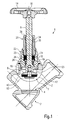
- Figure 1 shows a shut-off valve in longitudinal section in which the invention Valve shell 1 is screwed sealingly with a valve housing 2.
- the valve housing 2 has an inlet and an outlet through which the water can flow. These Flow can be throttled by hiring the valve top 1 against a valve seat 4 become.
- the spindle 6 In the upper valve part 1 is an actuating element, in Figure 1 as a rising spindle. 6 trained, guided.
- the spindle 6 At a lower end, the spindle 6 has a spindle head 17 on and carries the end face a valve element 7, consisting of a valve cone 8 and a conical seal 10 exists.
- the valve cone 8 and the conical seal 10 are connected by a Screw 12 connected to the spindle 6.
- a handwheel 14 also by means of a screw 16, with the spindle 6 against rotation connected.
- an oblique Transition 19 Between the spindle head 17 and a diameter in relation to the Diameter of the spindle head 17 reduced portion of the spindle 6, is an oblique Transition 19 provided.
- On the outer circumference of the spindle head 17 On the outer circumference of the spindle head 17 is an annular groove 18 recessed, the upper side surface obliquely formed inclined to the hand wheel 14 is.
- the housing of the upper valve part 1 is in two parts with an upper housing part 20 and a Housing base 22 is formed. Between the upper housing part 20 and the lower housing part 22 is a penetrated by the spindle 6 sealing element 24 is arranged. In the Detail enlargement in Figure 2 is between the spindle 6 and the lower housing part 22nd one of a valve chamber 2 enclosed by the valve chamber 2 to the bottom the sealing element 24 reaching passage 25 can be seen. In any Operating position is a flow through the passage 25 to the bottom of the Sealing element 24 possible. The flow takes place, for example, in the direction of in 2 arrow P. A front side of the sealing element upstream chamber 33rd is flowed through it, and the valve bonnet is therefore free of dead space.
- the lower half the wall 25 surrounding the wall of the lower housing part 22 opens conical, the valve cone 8 faces.
- the lower housing part 22 has a rectangular groove 26 for receiving a positioning means in the form of a snap ring 28 and a groove 30 for receiving a sealant in the form of an O-ring 32.
- the spindle 6 has approximately in its center a threaded projection 34, the upper end in the upper operating position shown in Figure 2 at a stop shoulder 36th of the upper housing part 20 abuts and which with an internal thread 35 of the upper housing part 20 is engaged.
- the spindle 6 is shown in FIG upper operating position of the spindle 6 in the exchange position shown in Figures 3 and 4 postponed. This is done by unscrewing the upper housing part 20 of the housing lower part 22 causes.
- the spindle 6 is inevitably by the threaded engagement with the Housing top 20 is connected and therefore pulled along in the axial direction. In this axial movement first slides the snap ring 28 via the oblique transition 19th and is thereby widened radially.
- With continuous displacement of the spindle is the Snap ring 28 and the O-ring 32 under radial bias to the spindle head 17 created.
- FIGS 5 and 6 show further embodiments of the area shown in Figure 4.
- FIG. 5 shows further embodiments of the area shown in Figure 4.
- FIG. 5 shows further embodiments of the area shown in Figure 4.
- FIG. 5 shows further embodiments of the area shown in Figure 4.
- FIG. 5 shows further embodiments of the area shown in Figure 4.
- the spindle head 17 is partially threaded on its outer peripheral surface 38 on.
- a collar 40 At the lower end of the spindle head 17 is a collar 40, with a larger one Diameter than the thread 38, formed.
- the collar 40 is defined by a groove 42 of the thread 38 separated.
- the inner peripheral surface of the lower housing part 22 has a Counter thread 39 to the thread 38. This thread 38, 39 must for mounting purposes be at least as large as the thread projection 34 of the spindle 6.
- the spindle 6 carries the valve cone 8 and the conical seal 10th
- the spindle 6 is moved from an upper operating position screwed into the replacement position.
- the thread 38 engages progressively Unscrewing into the mating thread 39 a.
- the spindle 6 is for adjustment the exchange position screwed back until an upper edge 44 of the collar 40 abuts a valve cone 8 facing surface 46 of the lower housing part 22.
- This peripheral edge 44 on the one hand before the replacement position and ensures on the other hand, that the spindle 6 sealed relative to the lower housing part 22 is. Thereafter, the upper housing part 20 by further rotation of the inevitably Spindle 6 unscrewed against the housing lower part 22 held is.
- FIG. 6 shows a further exemplary embodiment of the area enlarged in FIG shown.
- an annular groove 48 in the spindle head 17th spared.
- the annular groove 48 receives an O-ring 50.
- a collar 52 is formed whose diameter is larger than that of Spindle head 17.
- Front side of the spindle head 17 carries the spindle 6, the valve element 7th
- the spindle 6 is from an upper operating position in the exchange position by unscrewing of the upper housing part 20 relative to the lower housing part 22 is displaced so that the sealing element 24 can be replaced.
- the spindle 6 is in as long pushed axially until an upper edge 54 of the collar 52 at one of the valve cone 8 facing inclined surface 56 of the housing base 22 abuts and thereby dictates the exchange position.
- a mechanical locking of the spindle 6 is not necessary in this embodiment, since the pressure of the medium, the spindle 6 in holds this position.
- the O-ring 50 ensures that the Spindle 6 is sealed from the housing base 22.
Landscapes
- Engineering & Computer Science (AREA)
- General Engineering & Computer Science (AREA)
- Mechanical Engineering (AREA)
- Lift Valve (AREA)
- Feeding And Controlling Fuel (AREA)
- Details Of Valves (AREA)
- Beans For Foods Or Fodder (AREA)
- Centrifugal Separators (AREA)
- Multiple-Way Valves (AREA)
- Self-Closing Valves And Venting Or Aerating Valves (AREA)
Abstract
Description
Die Erfindung betrifft ein Ventiloberteil für ein Ventil mit einem Gehäuse, in dem ein Stellelement geführt ist, das an einem unteren, das Gehäuse überragenden Ende ein Ventilelement trägt, in dem ein von dem Stellelement durchragtes Dichtelement aufgenommen ist und das ein mit einem Ventilgehäuse dichtend verbindbares Gehäuseunterteil aufweist.The invention relates to a valve bonnet for a valve with a housing in which a Adjusting element is guided, the at a lower, the housing superior end Valve element carries in which a penetrated by the actuator sealing element added is and a sealable with a valve housing housing lower part having.
Ein derartiges Ventiloberteil ist beispielsweise aus der DE 197 05 982 C1 bekannt. Das gattungsgemäße Ventiloberteil weist ein Dichtelement auf, das zwischen einer nicht-steigenden Spindel und einem Führungsring angeordnet ist. Als Antriebselement für die Spindel dient ein Handrad, das drehfest mit der Spindel verbunden ist. Die Spindel steht mit einem Stellelement in Gewindeeingriff, welches von dem Ventilschaft eines Ventilelementes gebildet wird. Durch Drehung des Handrades kann das Ventilelement in verschiedene Betriebstellung gestellt werden. In einer oberen Betriebstellung ist das Ventil maximal geöffnet und das Ventilelement weist einen maximalen Abstand zu einem Ventilsitz auf. Um das Ventil zu schließen, wird das Ventilelement in axialer Richtung durch Drehung des Handrades gegen den Ventilsitz geschoben. Die untere Betriebsstellung ist erreicht, wenn das Ventilelement an dem Ventilsitz anliegt.Such a valve shell is known for example from DE 197 05 982 C1. The generic valve bonnet has a sealing element which is between a non-rising Spindle and a guide ring is arranged. As a driving element for the Spindle is a handwheel, which is rotatably connected to the spindle. The spindle is stationary with an actuating element in threaded engagement, which of the valve stem of a valve element is formed. By turning the handwheel, the valve element in different Operating position are provided. In an upper operating position is the valve maximum open and the valve element has a maximum distance to a valve seat on. To close the valve, the valve element in the axial direction through Rotation of the handwheel pushed against the valve seat. The lower operating position is achieved when the valve element rests against the valve seat.
Das Stellelement bei dem gattungsbildenden Stand der Technik ist durch den Ventilschaft nach Art eines Stößel gebildet. Als Stellelement im Sinne der vorliegenden Erfindung ist jedes Bauteil zu verstehen, welches mit dem Ventilelement verbunden und gegenüber dem Gehäuse axial verschiebbar ist. Das Stellelement kann aus einer steigenden oder nicht-steigenden Spindel oder als hydraulischer Stößel gebildet und kann auch ein- oder mehrteilig ausgebildet sein.The actuator in the generic state of the art is through the valve stem formed in the manner of a pestle. As an actuator in the context of the present invention is to understand each component, which is connected to the valve element and opposite the housing is axially displaceable. The actuator can be made of a rising or non-rising spindle or as a hydraulic plunger and can also be formed one or more parts.
Die Dichtelemente von Ventiloberteilen werden üblicherweise aus elastischen Werkstoffen hergestellt. Diese Dichtelemente sind in der Regel wartungsfrei, müssen aber nach längerer Betriebsdauer ausgetauscht werden.The sealing elements of valve bonnets are usually made of elastic materials manufactured. These sealing elements are usually maintenance-free, but must after longer service life.
Das Dichtelement wird bei dem gattungsbildenden Stand der Technik von unten her in das Gehäuse eingesetzt, und so kann das Dichtelement nicht während des Betriebes des Ventiloberteils ausgetauscht werden. Um das Dichtelement auszutauschen, muss sichergestellt werden, dass das Ventiloberteil drucklos ist. Erst nachdem das Ventil außer Betrieb genommen ist kann das Ventiloberteil abgeschraubt werden um den Austausch des Dichtelementes zu ermöglichen.The sealing element is in the generic state of the art from below in the housing is inserted, and so the sealing element can not during operation be replaced the valve shell. To replace the sealing element, must ensure that the valve bonnet is depressurised. Only after the valve except Operation is taken, the valve bonnet can be unscrewed to the exchange to allow the sealing element.
Der vorliegenden Erfindung liegt das Problem zugrunde das gattungsgemäße Ventiloberteil so auszugestalten, dass das Dichtelement auch während des Betriebs, d.h. während das Ventiloberteil unter Druck steht, ausgetauscht werden kann.The present invention is based on the problem the generic valve bonnet in such a way that the sealing element also during operation, i. while the valve bonnet is under pressure, can be replaced.
Das der Erfindung zugrundeliegende technische Problem wird durch ein Ventiloberteil
mit dem Merkmalen von Anspruch 1 gelöst, das sich dadurch vom Stand der Technik
unterscheidet, dass ein Gehäuseoberteil vorgesehen ist, welches lösbar mit dem Gehäuseunterteil
verbunden ist, dass das Dichtelement zwischen dem Gehäuseunterteil
und dem Gehäuseoberteil angeordnet ist und dass in einer Austauschstellung, in der
sich das Ventilelement nahe des Gehäuseunterteils befindet, zwischen dem Dichtelement
und dem Ventilelement das Stellelement gegenüber dem Gehäuseunterteil abgedichtet
ist.The technical problem underlying the invention is achieved by a valve top
solved with the features of
Die Austauschstellung ist dadurch gekennzeichnet, dass sich das Stellelement in einer bestimmten Position oberhalb der obersten Betriebstellung befindet. In der Austauschstellung ist ein beliebiges Dichtmittel wirksam, das das Stellelement gegenüber dem Gehäuseunterteil abdichtet. Das Gehäuse ist mehrteilig ausgeformt, um den Austausch des Dichtelementes während des Betriebes zu ermöglichen. Zum Austausch des Dichtelementes muss das Gehäuseoberteil von dem Gehäuseunterteil gelöst werden. Nachdem das Gehäuseoberteil gelöst worden ist, wird es in axialer Richtung abgezogen, so dass das Dichtelement für den direkten Zugriff frei liegt. In der Austauschstellung übernimmt das Dichtmittel die Funktion das Stellelement gegenüber dem Gehäuseunterteil abzudichten. Das Dichtelement kann deshalb, obwohl das Ventiloberteil unter Druck steht, problemlos ausgetauscht werden. Mit dem erfindungsgemäßen Ventiloberteil ist es daher möglich, das Dichtelement auch während des Betriebs, d.h. während das Ventiloberteil unter Druck steht, auszutauschen. Eine dauerhafte Betriebsicherheit kann damit gewährleistet werden. The replacement position is characterized in that the actuator in a certain position above the top operating position. In the exchange position is effective any sealant that the actuator over the Housing bottom seals. The housing is formed in several parts to exchange allow the sealing element during operation. To replace the sealing element the upper part of the housing must be detached from the lower part of the housing. After this the upper housing part has been solved, it is withdrawn in the axial direction, so that the sealing element is exposed for direct access. In the exchange position takes over the sealant the function of the actuator relative to the lower housing part seal. The sealing element can therefore, although the valve bonnet under pressure stands, easily exchanged. With the valve upper part according to the invention Therefore, it is possible, the sealing element during operation, i. while the valve head is under pressure to replace. A lasting operational safety can thus be guaranteed.
Gemäß einer bevorzugten Weiterbildung der Erfindung ist in einer beliebigen Betriebsstellung des Stellelementes zwischen dem Stellelement und dem Gehäuseunterteil ein Durchgang bis an die Unterseite des Dichtelementes vorgesehen.According to a preferred embodiment of the invention is in any operating position of the adjusting element between the actuating element and the lower housing part Passage provided to the underside of the sealing element.
Bei dieser vorteilhaften Weiterbildung erfolgt die Durchströmung des Ventiloberteils bis an die Unterseite des Dichtelementes, so dass ein Totraum vermieden werden kann, in dem eine gesundheitsschädliche Verkeimung des Wassers zu befürchten ist.In this advantageous development, the flow through the valve upper part takes place until to the underside of the sealing element, so that a dead space can be avoided, in which is to be feared a harmful microbial contamination of the water.
Gemäß einer weiteren bevorzugten Weiterbildung des erfindungsgemäßen Ventiloberteils ist das Gehäuseoberteil von dem Gehäuseunterteil in Bewegungsrichtung des Stellelementes abziehbar und ein in einer oberen Betriebsstellung des Stellelementes wirksamer Mitnehmer ist vorgesehen, durch den das Stellelement mit dem Gehäuseoberteil in Bewegungsrichtung des Stellelementes gekoppelt ist. Der in der obersten Betriebstellung wirksame Mitnehmer kann beispielsweise als ein Zapfen oder ähnliches Element ausgebildet sein, durch welches eine Kopplung zwischen dem Stellelement und dem Gehäuseoberteil hergestellt wird. Das Stellelement wird durch eine axiale Bewegung, also eine Bewegung in Bewegungsrichtung des Stellelementes, in die oberste Betriebsstellung geschoben. Die oberste Betriebsstellung ist erst dann erreicht, wenn das Ventil eine maximale Öffnung aufweist. Wenn das Gehäuseoberteil von dem Gehäuseunterteil gelöst wird sorgt der Mitnehmer dafür, dass das Stellelement in axialer Richtung mitgezogen und weiter von dem Ventilsitz weg und in Richtung auf das Gehäuseunterteil hin bewegt wird. Der Vorteil eines derartigen Mitnehmers ist, dass eine zwangsläufige Kopplung hergestellt werden kann.According to a further preferred embodiment of the valve top part according to the invention is the upper housing part of the housing lower part in the direction of movement of Stellelementes removable and a in an upper operating position of the control element effective driver is provided by the actuator with the upper housing part is coupled in the direction of movement of the actuating element. The one in the top one Operating position effective driver can, for example, as a pin or the like Element be formed, through which a coupling between the actuator and the housing top is made. The actuator is controlled by an axial movement, So a movement in the direction of movement of the control element, in the top Operating position pushed. The highest operating position is reached only when the valve has a maximum opening. If the upper housing part of the lower housing part is solved, the driver ensures that the actuator in the axial Direction pulled along and further away from the valve seat and towards the lower housing part is moved. The advantage of such a driver is that a inevitable coupling can be made.
Gemäß einer weiteren bevorzugten Weiterbildung des erfindungsgemäßen Ventiloberteils ist der Mitnehmer durch den Eingriff eines Gewindes gebildet, durch welches das Stellelement und das Gehäuseoberteil im Gewindeeingriff gehalten sind. Der Vorteil dieser Weiterbildung ist, dass eine zwangsläufige Kopplung hergestellt wird, durch die das Stellelement nach Art einer steigenden Spindel mit dem Gehäuse zusammenwirkt.According to a further preferred embodiment of the valve top part according to the invention the driver is formed by the engagement of a thread through which the Control element and the upper housing part are held in threaded engagement. The advantage of this Continuing education is that an inevitable coupling is made through which the Control element cooperates with the housing in the manner of a rising spindle.
Gemäß einer bevorzugten Weiterbildung des erfindungsgemäßen Ventiloberteils weist das Stellelement an seinem unteren Ende einen im Durchmesser vergrößerten Bereich auf und es sind in der Austauschstellung zwischen dem Stellelement und dem Gehäuseunterteil wirksame Positionier- und Dichtmittel vorgesehen.According to a preferred embodiment of the valve upper part according to the invention the actuator at its lower end an enlarged diameter area on and it is in the replacement position between the actuator and the housing base effective positioning and sealing means provided.
Die Positionier- und Dichtmittel können sowohl in dem Gehäuseunterteil als auch in dem Stellelement aufgenommen sein. Als Positioniermittel ist jedes Bauteil zu verstehen, das in der Lage ist, eine bestimmte Position des Stellelementes relativ zu dem Gehäuseunterteil vorzugeben und/oder zu sichern. Der im Durchmesser vergrößerte Bereich weist einen Übergang zu einem im Durchmesser verringerten Bereich des Stellelementes auf. In einer beliebigen Betriebsstellung ist eine Durchströmung des Durchgangs bis zu dem im Durchmesser verringerten Bereich möglich, da der im Durchmesser vergrößerten Bereich mit Abstand zu dem Gehäuseunterteil in Richtung auf den Ventilsitz verschoben ist und Fluid auf der Rückseite des im Durchmesser vergrößerten Bereichs vorbei an dem im Durchmesser verringerten Bereich des Stellelementes zu dem Dichtelement gelangen kann. Bei einer Verschiebung des Stellelementes von der oberen Betriebsstellung in die Austauschstellung gibt das Positioniermittel die Austauschstellung vor. In der Austauschstellung sorgt das Dichtmittel dafür, dass beim Austausch des Dichtelementes das Stellelement gegenüber dem Gehäuseunterteil abgedichtet ist. In dieser Stellung ist eine Durchströmung des Durchgangs nicht möglich.The positioning and sealing means can both in the housing base and in be added to the actuator. As a positioning means is to understand each component, which is capable of a certain position of the actuating element relative to the housing lower part pretend and / or secure. The area enlarged in diameter has a transition to a reduced diameter portion of the control element on. In any operating position is a flow through the passage possible up to the reduced diameter range because of the diameter enlarged area at a distance from the housing lower part in the direction of the Valve seat is displaced and fluid on the back of the enlarged in diameter Area past the reduced diameter portion of the actuator to can reach the sealing element. At a displacement of the actuating element of the upper operating position in the replacement position, the positioning means gives the replacement position in front. In the replacement position, the sealant ensures that when replacing of the sealing element, the adjusting element sealed against the lower housing part is. In this position, a flow through the passage is not possible.
Gemäß einer bevorzugten Weiterbildung des erfindungsgemäßen Ventiloberteils ist das Positioniermittel durch ein Gewinde gebildet. Diese vorteilhafte Ausgestaltung des Positioniermittels gewährleistet eine sichere Austauschstellung.According to a preferred embodiment of the valve top part according to the invention that is Positioning means formed by a thread. This advantageous embodiment of the positioning ensures a safe replacement position.
Gemäß einer weiteren bevorzugten Weiterbildung des erfindungsgemäßen Ventiloberteils ist das Positioniermittel durch einen Sprengring gebildet, welcher in dem Gehäuseunterteil oder dem Stellelement aufgenommen ist und in der Austauschstellung in einer an dem Außenumfang des im Durchmesser vergrößerten Bereichs beziehungsweise dem Gehäuseunterteil ausgesparten Ringnut im Eingriff ist, deren eine Seitenfläche schräg die Ringnut radial vergrößernd ausgebildet ist. Das Positioniermittel kann in dem Gehäuseunterteil als auch in dem Stellelement aufgenommen sein. Sofern das Positioniermittel im Gehäuseunterteil aufgenommen ist, weist der Außenumfang des im Durchmesser vergrößerten Bereichs eine Ringnut auf, deren obere Seitenfläche schräg ausgebildet ist. Sollte aber der Sprengring in dem im Durchmesser vergrößerten Bereich des Stellelementes aufgenommen sein, so weist das Gehäuseunterteil eine Ringnut auf deren untere Seitenfläche schräg ausgebildet ist. Diese schräge Ausformung führt bei beiden Alternativen dazu, dass der Sprengring in radialer Richtung vorgespannt und aus der Ringnut geschoben wird, wenn das Stellelement von der Austauschstellung in eine beliebige Betriebsstellung verschoben wird.According to a further preferred embodiment of the valve top part according to the invention the positioning means is formed by a snap ring, which in the housing lower part or the adjusting element is received and in the replacement position in a on the outer periphery of the enlarged diameter portion or the housing lower part recessed annular groove is engaged, whose one side surface obliquely the annular groove is formed radially enlarging. The positioning can in the Housing bottom part and be included in the actuator. If the positioning means is accommodated in the lower housing part, the outer circumference of the im Diameter enlarged area an annular groove, whose upper side surface obliquely is trained. But should the snap ring in the enlarged diameter area be received in the control element, the lower housing part has an annular groove the lower side surface is formed obliquely. This oblique formation leads both alternatives to the snap ring biased in the radial direction and off the annular groove is pushed when the actuator from the exchange position into a any operating position is moved.
Vorzugsweise umfasst das Dichtmittel einen zwischen dem Außenumfang des im Durchmesser vergrößerten Bereiches und dem Gehäuseunterteil vorgesehenen Dichtring. Der Dichtring gewährleistet eine sichere Abdichtung des Stellelementes gegenüber dem Gehäuseunterteil.Preferably, the sealing means comprises a between the outer periphery of the im Diameter enlarged area and the housing lower part provided sealing ring. The sealing ring ensures a secure sealing of the actuating element opposite the lower housing part.
Gemäß einer weiteren bevorzugten Weiterbildung des erfindungsgemäßen Ventiloberteils umfasst das Positioniermittel einen benachbart zu dem Ventilelement ausgeformten Kragen, der in der Austauschstellung an dem Gehäuseunterteil anliegt. Der Kragen, der an dem unteren Ende des Stellelementes ausgebildet ist, gibt die Austauschstellung vor, in welcher der Kragen an dem Gehäuseunterteil anliegt, und stoppt die Bewegung des Stellelementes relativ zu dem Gehäuseunterteil bei einer Bewegung aus der oberen Betriebslellung in die Austauschstellung.According to a further preferred embodiment of the valve top part according to the invention the positioning means comprises a member formed adjacent to the valve element Collar, which rests in the replacement position on the housing lower part. The collar, the is formed at the lower end of the actuating element, specifies the replacement position, in which the collar rests against the housing lower part, and stops the movement of the Stellelementes relative to the lower housing part in a movement from the upper Operation in the replacement position.
Vorzugsweise liegt der Kragen dichtend an, so dass der Kragen einerseits die Austauschstellung vorgibt und anderseits das Stellelement gegenüber dem Gehäuseunterteil abdichtet.Preferably, the collar is sealing, so that the collar on the one hand, the exchange position pretends and on the other hand, the actuator relative to the lower housing part seals.
Gemäß einer weiteren bevorzugten Weiterbildung des erfindungsgemäßen Ventiloberteils liegt eine obere Kante des Kragens dichtend an einer dem Ventilelement zugewandten schrägen Fläche des Gehäuseunterteils an. Da die obere Kante des Kragens dichtend an der schrägen Fläche anliegt, ergibt sich zwischen dem Gehäuseunterteil und dem Kragen eine hohe Flächenpressung. Das Gehäuseunterteil und der Kragen werden üblicherweise aus Rotguss oder einer Messinglegierung hergestellt, so dass auf grund der hohen Flächenpressung das Stellelement gegenüber dem Gehäuseunterteil abgedichtet werden kann, ohne dass gesonderte, stofffremde Dichtmittel aus elastischen Materialien vorgesehen sein müssen. Die Abdichtung wird also nur durch für Armaturen übliche metallische Materialen erzeugt. According to a further preferred embodiment of the valve top part according to the invention an upper edge of the collar sealingly faces a valve member facing sloping surface of the housing base. Because the top edge of the collar sealingly abuts the inclined surface, results between the lower housing part and the collar a high surface pressure. The housing base and the collar are usually made of gunmetal or a brass alloy, so that on Because of the high surface pressure the actuator relative to the lower housing part can be sealed without separate, fabric-free elastic sealant Materials must be provided. The seal is therefore only for valves produced usual metallic materials.
Gemäß einer bevorzugten Weiterbildung des erfindungsgemäßen Ventiloberteils wird das Stellelement und/oder das Gehäuseunterteil aus einem anderen Werkstoff als das Gehäuseoberteil hergestellt. Bei dieser bevorzugten Ausgestaltung können das Gehäuseoberteil und/oder das Stellelement aus einem verhältnismäßig hochwertigen, insbesondere den Anforderungen an die Korrosionsbeständigkeit genügenden Werkstoff gebildet sein, wohingegen bei der Auswahl des Werkstoffs für das Gehäuseoberteil derartige Anforderungen unberücksichtigt bleiben können. Ferner weist diese vorteilhafte Ausgestaltung den Vorteil auf, dass der Verschleiß im Bereich des Gewindeeingriffs zwischen dem Stellelement und dem Gehäuseoberteil gering gehalten werden kann, da bei unterschiedlichen Werkstoffpaarungen bei Bewegungsgewinden weniger Reibung an den Berührungsflächen erzeugt wird.According to a preferred embodiment of the valve upper part according to the invention the control element and / or the lower housing part of a different material than that Housing top made. In this preferred embodiment, the upper housing part and / or the actuator of a relatively high quality, in particular the requirements of the corrosion resistance sufficient material formed whereas, in selecting the material for the upper housing part, such Requirements can be disregarded. Furthermore, this has advantageous Design on the advantage that the wear in the threaded engagement can be kept low between the actuator and the upper housing part, since with different material pairings with movement threads less friction is generated at the contact surfaces.
Weitere Einzelheiten, Vorteile und Merkmale der vorliegenden Erfindung ergeben sich aus der nachfolgenden Beschreibung einiger Ausführungsbeispiele in Verbindung mit der Zeichnung. In dieser zeigen:
- Fig. 1
- eine Längsschnittansicht eines Ventils mit einem ersten Ausführungsbeispiel des erfindungsgemäßen Ventiloberteils;
- Fig. 2
- eine Detailvergrößerung des in
Figur 1 dargestellten Bereichs Z; - Fig. 3
- die in
Figur 1 gezeigte Darstellung, wobei sich das erfindungsgemäße Ventiloberteil in der Austauschstellung befindet; - Fig. 4
- eine Detailvergrößerung des in Figur 3 dargestellten Bereichs V;
- Fig. 5
- ein zweites Ausführungsbeispiel für den in
Figur 4 dargestellten Bereich; und - Fig. 6
- ein drittes Ausführungsbeispiel für den in
Figur 4 dargestellten Bereich.
- Fig. 1
- a longitudinal sectional view of a valve with a first embodiment of the valve top part according to the invention;
- Fig. 2
- an enlarged detail of the area Z shown in Figure 1;
- Fig. 3
- the representation shown in Figure 1, wherein the valve upper part according to the invention is in the exchange position;
- Fig. 4
- an enlarged detail of the area V shown in Figure 3;
- Fig. 5
- A second embodiment of the area shown in Figure 4; and
- Fig. 6
- a third embodiment of the area shown in Figure 4.
Figur 1 zeigt ein Absperrventil in Längsschnittdarstellung in dem das erfindungsgemäße
Ventiloberteil 1 mit einem Ventilgehäuse 2 dichtend verschraubt ist. Das Ventilgehäuse
2 weist einen Einlass und einen Auslas auf, durch den das Wasser strömen kann. Diese
Strömung kann durch das Anstellen des Ventiloberteils 1 gegen einen Ventilsitz 4 gedrosselt
werden.Figure 1 shows a shut-off valve in longitudinal section in which the
In dem Ventiloberteil 1 wird ein Stellelement, in Figur 1 als eine steigende Spindel 6
ausgebildet, geführt. An einem unteren Ende weist die Spindel 6 einen Spindelkopf 17
auf und trägt stirnseitig ein Ventilelement 7, das aus einem Ventilkegel 8 und einer Kegeldichtung
10 besteht. Der Ventilkegel 8 und die Kegeldichtung 10 sind durch eine
Schraube 12 mit der Spindel 6 verbunden. An dem anderen, oberen Ende der Spindel 6
ist ein Handrad 14, ebenfalls mittels einer Schraube 16, mit der Spindel 6 verdrehfest
verbunden. Zwischen dem Spindelkopf 17 und einem im Durchmesser gegenüber dem
Durchmesser des Spindelkopfes 17 verringerten Bereich der Spindel 6, ist ein schräger
Übergang 19 vorgesehen. An dem Außenumfang des Spindelkopfes 17 ist eine Ringnut
18 ausgespart, deren obere Seitenfläche schräg, zu dem Handrad 14 geneigt ausgebildet
ist.In the
Das Gehäuse des Ventiloberteils 1 ist zweiteilig mit einen Gehäuseoberteil 20 und einen
Gehäuseunterteil 22 ausgebildet. Zwischen dem Gehäuseoberteil 20 und dem Gehäuseunterteil
22 ist ein von der Spindel 6 durchragtes Dichtelement 24 angeordnet. In der
Detailvergrößerung in Figur 2 ist zwischen der Spindel 6 und dem Gehäuseunterteil 22
ein von einem von dem Ventilgehäuse 2 umschlossenen Ventilraum bis an die Unterseite
des Dichtelementes 24 reichender Durchgang 25 zu erkennen. In einer beliebigen
Betriebsstellung ist eine Durchströmung des Durchganges 25 bis zu der Unterseite des
Dichtelementes 24 möglich. Die Durchströmung erfolgt beispielsweise in Richtung des in
Fig. 2 dargestellten Pfeils P. Eine stirnseitig dem Dichtelement vorgelagerte Kammer 33
wird dadurch durchströmt, und das Ventiloberteil ist deshalb totraumfrei. Die untere Hälfte
der den Durchgang 25 umgebenden Wandung des Gehäuseunterteils 22 öffnet sich
konisch, dem Ventilkegel 8 zugewandt. In der oberen Hälfte des Durchganges 25 weist
das Gehäuseunterteil 22 eine rechteckige Nut 26 zur Aufnahme eines Positioniermittels
in Form eines Sprengrings 28 und eine Nut 30 zur Aufnahme eines Dichtmittels in Form
eines O-Rings 32 auf.The housing of the
Die Spindel 6 hat in etwa in ihrer Mitte einen Gewindevorsprung 34, dessen oberes Ende
sich in der in Figur 2 gezeigten oberen Betriebsstellung an einer Anschlagschulter 36
des Gehäuseoberteils 20 anliegt und welcher mit einem Innengewinde 35 des Gehäuseoberteils
20 im Eingriff ist. In der oberen Betriebsstellung der Spindel 6 ist das die
Strömung beim Betrieb regulierende Ventilelement 8, 10 beim Betrieb des Ventiloberteils
maximal von dem Ventilsitz 4 entfernt.The
Um das Dichtelement 24 auszutauschen wird die Spindel 6 von der in Figur 1 gezeigten
oberen Betriebsstellung der Spindel 6 in die in Figur 3 und 4 gezeigte Austauschstellung
verschoben. Dies wird durch Abschrauben des Gehäuseoberteils 20 von dem Gehäuseunterteil
22 bewirkt. Die Spindel 6 ist durch den Gewindeeingriff zwangsläufig mit dem
Gehäuseoberteil 20 verbunden und wird deshalb in axiale Richtung mitgezogen. In dieser
axialen Bewegung gleitet zuerst der Sprengring 28 über den schrägen Übergang 19
und wird dadurch radial geweitet. Bei fortlaufender Verschiebung der Spindel wird der
Sprengring 28 und auch der O-Ring 32 unter radialer Vorspannung an den Spindelkopf
17 angelegt. In dem Augenblick, in dem das Gehäuseoberteil 20 komplett von dem Gehäuseunterteil
22 abgeschraubt ist, rastet der Sprengring 28 in die Ringnut 18 ein und
fixiert die Spindel 6 in Abschraubbewegung gegenüber dem Gehäuseunterteil 22 und
der O-Ring 32 dichtet die Spindel 6 gegenüber dem Gehäuseunterteil 22 ab. Die Spindel
6 befindet sich nun in der Austauschstellung, siehe Figur 3 und 4. Bei forschreitender
Abschraubbewegung wird das Gehäuseoberteil 20 komplett von der nun fixierten Spindel
6 gelöst. Nach dem Entfernen des Handrades 14 kann dann das Gehäuseoberteil 20
entfernt werden, so dass das Dichtelement 24 für den direkten Zugriff frei liegt. Nachdem
das Dichtelement 24 ausgetauscht worden ist, erfolgt die Fertigmontage in umgekehrter
Reihenfolge. Danach ist das Absperrventil wieder voll funktionsfähig. Wenn die
Spindel 6 von der Austauschstellung in eine beliebige Betriebsstellung geschoben wird,
gleitet der Sprengring 28 über die obere, zu dem Handrad 14 geneigte Seitenfläche der
Ringnut 18 und wird so aus der Ringnut 18 gedrängt, wodurch die Fixierung der Spindel
6 gelöst wird.To replace the sealing
Figur 5 und 6 zeigen weitere Ausführungsbeispiele des in Figur 4 dargestellten Bereichs. In diesen Figuren sind gegenüber dem Ausführungsbeispiel der Figur 1 bis 4 gleiche Teile, mit den selben Bezugszeichen gekennzeichnet. Figures 5 and 6 show further embodiments of the area shown in Figure 4. In these figures, with respect to the embodiment of Figures 1 to 4 like parts, marked with the same reference numerals.
In Figur 5 weist der Spindelkopf 17 an seiner Außenumfangsfläche teilweise ein Gewinde
38 auf. Am unteren Ende des Spindelkopfes 17 ist ein Kragen 40, mit einen größeren
Durchmesser als das Gewinde 38, ausgeformt. Der Kragen 40 ist durch eine Nut 42 von
dem Gewinde 38 getrennt. Die Innenumfangsfläche des Gehäuseunterteils 22 weist ein
Gegengewinde 39 zu dem Gewinde 38 auf. Dieses Gewinde 38, 39 muss für Montagezwecke
mindestens so groß sein wie der Gewindevorsprung 34 der Spindel 6. Stirnseitig
zu dem Spindelkopf 17 trägt die Spindel 6 den Ventilkegel 8 und die Kegeldichtung 10.In FIG. 5, the
Um das Dichtelement 24 auszutauschen wird die Spindel 6 von einer oberen Betriebsstellung
in die Austauschstellung geschraubt. Das Gewinde 38 greift bei fortschreitender
Abschraubbewegung in das Gegengewinde 39 ein. Die Spindel 6 wird zur Einstellung
der Austauschstellung so lange zurückgeschraubt, bis eine obere Kante 44 des Kragens
40 an einer dem Ventilkegel 8 zugewandten Fläche 46 des Gehäuseunterteils 22 anliegt.
Diese umlaufende Kante 44 gibt einerseits die Austauschstellung vor und sorgt
anderseits dafür, dass die Spindel 6 gegenüber dem Gehäuseunterteil 22 abgedichtet
ist. Danach wird das Gehäuseoberteil 20 durch weiteres Drehen zwangsläufig von der
Spindel 6 abgeschraubt die verdrehfest gegenüber dem Gehäuseunterteil 22 gehalten
ist.To replace the sealing
In Figur 6 ist ein weiteres Ausführungsbeispiel des im Figur 4 vergrößerten Bereichs
dargestellt. In diesem Ausführungsbeispiel ist eine Ringnut 48 in dem Spindelkopf 17
ausgespart. Die Ringnut 48 nimmt einen O-Ring 50 auf. Am unteren Ende des Spindelkopfes
17 ist ein Kragen 52 ausgeformt, dessen Durchmesser größer ist als der des
Spindelkopfes 17. Stirnseitig des Spindelkopfes 17 trägt die Spindel 6 das Ventilelement
7.FIG. 6 shows a further exemplary embodiment of the area enlarged in FIG
shown. In this embodiment, an
Die Spindel 6 wird von einer oberen Betriebstellung in die Austauschstellung durch Abschrauben
des Gehäuseoberteils 20 gegenüber den Gehäuseunterteil 22 verlagert, so
dass das Dichtelement 24 ausgetauscht werden kann. Die Spindel 6 wird solange in
axiale Richtung geschoben, bis eine obere Kante 54 des Kragens 52 an einer dem Ventilkegel
8 zugewandten schrägen Fläche 56 des Gehäuseunterteils 22 anschlägt und
dadurch die Austauschstellung vorgibt. Eine mechanische Verriegelung der Spindel 6 ist
im diesem Ausführungsbeispiel nicht nötig, da der Druck des Mediums die Spindel 6 in
dieser Stellung hält. In dieser Austauschstellung sorgt der O-Ring 50 dafür, dass die
Spindel 6 gegenüber dem Gehäuseunterteil 22 abgedichtet ist. The
- 11
- VentiloberteilValve top
- 22
- Ventilgehäusevalve housing
- 44
- Ventilsitzvalve seat
- 66
- Spindelspindle
- 77
- Ventilelementvalve element
- 88th
- Ventilkegelshuttle
- 1010
- Kegeldichtungconical seal
- 1212
- Schraubescrew
- 1414
- Handradhandwheel
- 1616
- Schraubescrew
- 1717
- Spindelkopfspindle head
- 1818
- Ringnutring groove
- 1919
- Übergangcrossing
- 2020
- GehäuseoberteilHousing top
- 2222
- GehäuseunterteilHousing bottom
- 2424
- Dichtelementsealing element
- 2525
- Durchgangpassage
- 2626
- Nutgroove
- 2828
- Sprengringsnap ring
- 3030
- Nutgroove
- 3232
- O-RingO-ring
- 3333
- Kammerchamber
- 3434
- Gewindevorsprungthreaded boss
- 3535
- Innengewindeinner thread
- 3636
- Anschlagschulterstop shoulder
- 3838
- Gewindethread
- 3939
- Gewindethread
- 4040
- Kragencollar
- 4242
- Nutgroove
- 4444
- Kanteedge
- 4646
- Fläche surface
- 4848
- Ringnutring groove
- 5050
- O-RingO-ring
- 5252
- Kragencollar
- 5454
- Kanteedge
- 5656
- Flächesurface
Claims (13)
dadurch gekennzeichnet, dass ein Gehäuseoberteil (20) vorgesehen ist, welches lösbar mit dem Gehäuseunterteil (22) verbunden ist, dass das Dichtelement (24) zwischen dem Gehäuseunterteil (22) und dem Gehäuseoberteil (20) angeordnet ist und dass in einer Austauschstellung, in der sich das Ventilelement (7) nahe des Gehäuseunterteils (22) befindet, zwischen dem Dichtelement (24) und dem Ventilelement (7) das Stellelement (6) gegenüber dem Gehäuseunterteil (22) abgedichtet ist.Upper valve part for a valve with a housing in which an adjusting element (6) is guided, which carries at a lower, the housing projecting end of a valve element (7), in which a of the adjusting element (6) penetrated by sealing element (24) is received and which has a housing lower part (22) which can be sealingly connected to a valve housing (2),
characterized in that an upper housing part (20) is provided, which is releasably connected to the lower housing part (22), that the sealing element (24) between the lower housing part (22) and the upper housing part (20) is arranged and that in an exchange position, in the valve element (7) is located close to the lower housing part (22), between the sealing element (24) and the valve element (7) the actuating element (6) is sealed relative to the lower housing part (22).
Applications Claiming Priority (2)
| Application Number | Priority Date | Filing Date | Title |
|---|---|---|---|
| DE10335995A DE10335995B4 (en) | 2003-08-01 | 2003-08-01 | Valve top |
| DE10335995 | 2003-08-01 |
Publications (2)
| Publication Number | Publication Date |
|---|---|
| EP1503123A1 true EP1503123A1 (en) | 2005-02-02 |
| EP1503123B1 EP1503123B1 (en) | 2009-04-01 |
Family
ID=33521544
Family Applications (1)
| Application Number | Title | Priority Date | Filing Date |
|---|---|---|---|
| EP04016482A Expired - Lifetime EP1503123B1 (en) | 2003-08-01 | 2004-07-13 | Upper part of a valve |
Country Status (4)
| Country | Link |
|---|---|
| EP (1) | EP1503123B1 (en) |
| AT (1) | ATE427444T1 (en) |
| DE (2) | DE10335995B4 (en) |
| DK (1) | DK1503123T3 (en) |
Families Citing this family (2)
| Publication number | Priority date | Publication date | Assignee | Title |
|---|---|---|---|---|
| DE102009057611A1 (en) | 2009-12-09 | 2011-06-16 | Theodor Nocon | Stop valve for liquids, has functional upper part and sealing parts repaired or exchanged by assembly watergate under operating conditions, and valve body exhibiting additional external thread to attach assembly watergate to valve housing |
| DE202009017617U1 (en) | 2009-12-29 | 2010-05-12 | Nocon, Theodor | Repair and replacement device |
Citations (6)
| Publication number | Priority date | Publication date | Assignee | Title |
|---|---|---|---|---|
| US686854A (en) * | 1901-02-20 | 1901-11-19 | Charles E Huxley | Valve. |
| US3295856A (en) * | 1963-12-13 | 1967-01-03 | Crane Co | Stuffing box arrangement for valves |
| US3777783A (en) * | 1971-10-06 | 1973-12-11 | Kunkle Valve Co Inc | Valve and method of making the same |
| US3993285A (en) * | 1975-08-18 | 1976-11-23 | Rockwell International Corporation | Double disc gate valve with entrapped stem connection |
| US4601304A (en) * | 1984-08-09 | 1986-07-22 | Schobl Howard T | Valve assembly |
| US5454547A (en) * | 1993-06-14 | 1995-10-03 | Valve Sales Company, Inc. | Sleeved seal for a valve |
Family Cites Families (7)
| Publication number | Priority date | Publication date | Assignee | Title |
|---|---|---|---|---|
| CH28420A (en) * | 1903-06-26 | 1904-04-30 | Balduin Weisser | Improved steam valve |
| US2780233A (en) * | 1951-03-06 | 1957-02-05 | Alexander S Volpin | Through conduit gate valve |
| DD72951A1 (en) * | 1969-01-24 | 1970-05-05 | Spindle backsight for slides | |
| DE2920643A1 (en) * | 1979-05-22 | 1980-12-04 | Thyssen Industrie | Gate valve spindle seal - has elastic location bush to seal back pressure when valve is fully open |
| DE3404982A1 (en) * | 1984-02-11 | 1985-08-22 | Deutsche Babcock Werke AG, 4200 Oberhausen | QUICK-CLOSING CHECK VALVE |
| DE3828561C2 (en) * | 1988-08-23 | 1997-04-30 | Immanuel Jeschke | Gate valve |
| DE19705982C1 (en) * | 1997-02-17 | 1998-08-06 | Seppelfricke Armaturen Gmbh & | Valve for controlling fluid flow |
-
2003
- 2003-08-01 DE DE10335995A patent/DE10335995B4/en not_active Expired - Fee Related
-
2004
- 2004-07-13 AT AT04016482T patent/ATE427444T1/en active
- 2004-07-13 EP EP04016482A patent/EP1503123B1/en not_active Expired - Lifetime
- 2004-07-13 DK DK04016482T patent/DK1503123T3/en active
- 2004-07-13 DE DE502004009258T patent/DE502004009258D1/en not_active Expired - Lifetime
Patent Citations (6)
| Publication number | Priority date | Publication date | Assignee | Title |
|---|---|---|---|---|
| US686854A (en) * | 1901-02-20 | 1901-11-19 | Charles E Huxley | Valve. |
| US3295856A (en) * | 1963-12-13 | 1967-01-03 | Crane Co | Stuffing box arrangement for valves |
| US3777783A (en) * | 1971-10-06 | 1973-12-11 | Kunkle Valve Co Inc | Valve and method of making the same |
| US3993285A (en) * | 1975-08-18 | 1976-11-23 | Rockwell International Corporation | Double disc gate valve with entrapped stem connection |
| US4601304A (en) * | 1984-08-09 | 1986-07-22 | Schobl Howard T | Valve assembly |
| US5454547A (en) * | 1993-06-14 | 1995-10-03 | Valve Sales Company, Inc. | Sleeved seal for a valve |
Also Published As
| Publication number | Publication date |
|---|---|
| DE502004009258D1 (en) | 2009-05-14 |
| DE10335995B4 (en) | 2006-06-22 |
| DK1503123T3 (en) | 2009-07-06 |
| DE10335995A1 (en) | 2005-03-03 |
| ATE427444T1 (en) | 2009-04-15 |
| EP1503123B1 (en) | 2009-04-01 |
Similar Documents
| Publication | Publication Date | Title |
|---|---|---|
| DE69930849T2 (en) | VALVE WITH LARGE FLOW | |
| DE69421551T2 (en) | Diverter valve cartridge | |
| AT411923B (en) | HYDRAULIC VALVE | |
| DE2942363A1 (en) | TURNTABLE WITH INTERCHANGEABLE CARTRIDGE | |
| EP2453332B1 (en) | Flow regulator | |
| EP0715692B1 (en) | Pump-protecting valve | |
| DE60123112T2 (en) | FLOW MIXER | |
| DE102005052385B4 (en) | pressure reducer | |
| DE69614396T2 (en) | BALL VALVE | |
| DE2602498C2 (en) | ||
| DE1166571B (en) | Cock with O-ring seal and a plug supported by fixed cylindrical segment-shaped inserts | |
| DE2546399A1 (en) | ROTARY VALVE | |
| EP0882916B1 (en) | Valve assembly | |
| EP0401633B1 (en) | Backwashable filter mounting | |
| DE102012209031B4 (en) | Gate valves | |
| DE2553172A1 (en) | LIQUID VALVE | |
| DE60025315T2 (en) | sealing arrangement | |
| EP1503123B1 (en) | Upper part of a valve | |
| DE19812049A1 (en) | Liquid valve | |
| EP0501953A1 (en) | Tap-water mixer unit. | |
| DE2606042A1 (en) | VALVE FOR SHUT-OFF, THROTTLE OR REGULATING | |
| EP1348900B1 (en) | Excess flow valve		 | |
| DE1550468B2 (en) | DOUBLE SEAT VALVE | |
| AT411924B (en) | Hydraulic valve has insert body with cog-shaped cross-section with valve passages in tooth spaces and set on shoulder of housing inner chamber | |
| DE19636410B4 (en) | Faucet for water pipes |
Legal Events
| Date | Code | Title | Description |
|---|---|---|---|
| PUAI | Public reference made under article 153(3) epc to a published international application that has entered the european phase |
Free format text: ORIGINAL CODE: 0009012 |
|
| 17P | Request for examination filed |
Effective date: 20041201 |
|
| AK | Designated contracting states |
Kind code of ref document: A1 Designated state(s): AT BE BG CH CY CZ DE DK EE ES FI FR GB GR HU IE IT LI LU MC NL PL PT RO SE SI SK TR |
|
| AX | Request for extension of the european patent |
Extension state: AL HR LT LV MK |
|
| AKX | Designation fees paid |
Designated state(s): AT BE BG CH CY CZ DE DK EE ES FI FR GB GR HU IE IT LI LU MC NL PL PT RO SE SI SK TR |
|
| 17Q | First examination report despatched |
Effective date: 20051122 |
|
| GRAP | Despatch of communication of intention to grant a patent |
Free format text: ORIGINAL CODE: EPIDOSNIGR1 |
|
| GRAS | Grant fee paid |
Free format text: ORIGINAL CODE: EPIDOSNIGR3 |
|
| GRAA | (expected) grant |
Free format text: ORIGINAL CODE: 0009210 |
|
| AK | Designated contracting states |
Kind code of ref document: B1 Designated state(s): AT BE BG CH CY CZ DE DK EE ES FI FR GB GR HU IE IT LI LU MC NL PL PT RO SE SI SK TR |
|
| REG | Reference to a national code |
Ref country code: GB Ref legal event code: FG4D Free format text: NOT ENGLISH |
|
| REG | Reference to a national code |
Ref country code: CH Ref legal event code: EP |
|
| REG | Reference to a national code |
Ref country code: IE Ref legal event code: FG4D Free format text: LANGUAGE OF EP DOCUMENT: GERMAN |
|
| REF | Corresponds to: |
Ref document number: 502004009258 Country of ref document: DE Date of ref document: 20090514 Kind code of ref document: P |
|
| REG | Reference to a national code |
Ref country code: SE Ref legal event code: TRGR |
|
| REG | Reference to a national code |
Ref country code: CH Ref legal event code: NV Representative=s name: R. A. EGLI & CO. PATENTANWAELTE |
|
| REG | Reference to a national code |
Ref country code: DK Ref legal event code: T3 |
|
| PG25 | Lapsed in a contracting state [announced via postgrant information from national office to epo] |
Ref country code: SI Free format text: LAPSE BECAUSE OF FAILURE TO SUBMIT A TRANSLATION OF THE DESCRIPTION OR TO PAY THE FEE WITHIN THE PRESCRIBED TIME-LIMIT Effective date: 20090401 |
|
| PG25 | Lapsed in a contracting state [announced via postgrant information from national office to epo] |
Ref country code: PT Free format text: LAPSE BECAUSE OF FAILURE TO SUBMIT A TRANSLATION OF THE DESCRIPTION OR TO PAY THE FEE WITHIN THE PRESCRIBED TIME-LIMIT Effective date: 20090902 Ref country code: FI Free format text: LAPSE BECAUSE OF FAILURE TO SUBMIT A TRANSLATION OF THE DESCRIPTION OR TO PAY THE FEE WITHIN THE PRESCRIBED TIME-LIMIT Effective date: 20090401 Ref country code: ES Free format text: LAPSE BECAUSE OF FAILURE TO SUBMIT A TRANSLATION OF THE DESCRIPTION OR TO PAY THE FEE WITHIN THE PRESCRIBED TIME-LIMIT Effective date: 20090712 Ref country code: EE Free format text: LAPSE BECAUSE OF FAILURE TO SUBMIT A TRANSLATION OF THE DESCRIPTION OR TO PAY THE FEE WITHIN THE PRESCRIBED TIME-LIMIT Effective date: 20090401 |
|
| PG25 | Lapsed in a contracting state [announced via postgrant information from national office to epo] |
Ref country code: PL Free format text: LAPSE BECAUSE OF FAILURE TO SUBMIT A TRANSLATION OF THE DESCRIPTION OR TO PAY THE FEE WITHIN THE PRESCRIBED TIME-LIMIT Effective date: 20090401 |
|
| REG | Reference to a national code |
Ref country code: HU Ref legal event code: AG4A Ref document number: E006051 Country of ref document: HU |
|
| PG25 | Lapsed in a contracting state [announced via postgrant information from national office to epo] |
Ref country code: RO Free format text: LAPSE BECAUSE OF FAILURE TO SUBMIT A TRANSLATION OF THE DESCRIPTION OR TO PAY THE FEE WITHIN THE PRESCRIBED TIME-LIMIT Effective date: 20090401 |
|
| PLBE | No opposition filed within time limit |
Free format text: ORIGINAL CODE: 0009261 |
|
| STAA | Information on the status of an ep patent application or granted ep patent |
Free format text: STATUS: NO OPPOSITION FILED WITHIN TIME LIMIT |
|
| PG25 | Lapsed in a contracting state [announced via postgrant information from national office to epo] |
Ref country code: MC Free format text: LAPSE BECAUSE OF NON-PAYMENT OF DUE FEES Effective date: 20090731 |
|
| 26N | No opposition filed |
Effective date: 20100105 |
|
| PG25 | Lapsed in a contracting state [announced via postgrant information from national office to epo] |
Ref country code: BG Free format text: LAPSE BECAUSE OF FAILURE TO SUBMIT A TRANSLATION OF THE DESCRIPTION OR TO PAY THE FEE WITHIN THE PRESCRIBED TIME-LIMIT Effective date: 20090701 |
|
| REG | Reference to a national code |
Ref country code: FR Ref legal event code: ST Effective date: 20100331 |
|
| PG25 | Lapsed in a contracting state [announced via postgrant information from national office to epo] |
Ref country code: FR Free format text: LAPSE BECAUSE OF NON-PAYMENT OF DUE FEES Effective date: 20090731 |
|
| PG25 | Lapsed in a contracting state [announced via postgrant information from national office to epo] |
Ref country code: GR Free format text: LAPSE BECAUSE OF FAILURE TO SUBMIT A TRANSLATION OF THE DESCRIPTION OR TO PAY THE FEE WITHIN THE PRESCRIBED TIME-LIMIT Effective date: 20090702 |
|
| PG25 | Lapsed in a contracting state [announced via postgrant information from national office to epo] |
Ref country code: TR Free format text: LAPSE BECAUSE OF FAILURE TO SUBMIT A TRANSLATION OF THE DESCRIPTION OR TO PAY THE FEE WITHIN THE PRESCRIBED TIME-LIMIT Effective date: 20090401 |
|
| PG25 | Lapsed in a contracting state [announced via postgrant information from national office to epo] |
Ref country code: CY Free format text: LAPSE BECAUSE OF FAILURE TO SUBMIT A TRANSLATION OF THE DESCRIPTION OR TO PAY THE FEE WITHIN THE PRESCRIBED TIME-LIMIT Effective date: 20090401 |
|
| PGFP | Annual fee paid to national office [announced via postgrant information from national office to epo] |
Ref country code: TR Payment date: 20180926 Year of fee payment: 6 Ref country code: HU Payment date: 20180620 Year of fee payment: 15 |
|
| REG | Reference to a national code |
Ref country code: SE Ref legal event code: EUG |
|
| PG25 | Lapsed in a contracting state [announced via postgrant information from national office to epo] |
Ref country code: SE Free format text: LAPSE BECAUSE OF NON-PAYMENT OF DUE FEES Effective date: 20190714 Ref country code: HU Free format text: LAPSE BECAUSE OF NON-PAYMENT OF DUE FEES Effective date: 20190714 |
|
| PG25 | Lapsed in a contracting state [announced via postgrant information from national office to epo] |
Ref country code: IT Free format text: LAPSE BECAUSE OF NON-PAYMENT OF DUE FEES Effective date: 20190713 |
|
| PGFP | Annual fee paid to national office [announced via postgrant information from national office to epo] |
Ref country code: CZ Payment date: 20210625 Year of fee payment: 18 Ref country code: SK Payment date: 20210625 Year of fee payment: 18 |
|
| PGFP | Annual fee paid to national office [announced via postgrant information from national office to epo] |
Ref country code: NL Payment date: 20210721 Year of fee payment: 18 |
|
| PGFP | Annual fee paid to national office [announced via postgrant information from national office to epo] |
Ref country code: LU Payment date: 20210720 Year of fee payment: 18 Ref country code: IE Payment date: 20210723 Year of fee payment: 18 |
|
| PGFP | Annual fee paid to national office [announced via postgrant information from national office to epo] |
Ref country code: GB Payment date: 20210722 Year of fee payment: 18 Ref country code: DK Payment date: 20210722 Year of fee payment: 18 Ref country code: BE Payment date: 20210720 Year of fee payment: 18 |
|
| PGFP | Annual fee paid to national office [announced via postgrant information from national office to epo] |
Ref country code: DE Payment date: 20220622 Year of fee payment: 19 Ref country code: AT Payment date: 20220726 Year of fee payment: 19 |
|
| PGFP | Annual fee paid to national office [announced via postgrant information from national office to epo] |
Ref country code: CH Payment date: 20220718 Year of fee payment: 19 |
|
| REG | Reference to a national code |
Ref country code: SK Ref legal event code: MM4A Ref document number: E 5642 Country of ref document: SK Effective date: 20220713 |
|
| REG | Reference to a national code |
Ref country code: DK Ref legal event code: EBP Effective date: 20220731 |
|
| REG | Reference to a national code |
Ref country code: NL Ref legal event code: MM Effective date: 20220801 |
|
| GBPC | Gb: european patent ceased through non-payment of renewal fee |
Effective date: 20220713 |
|
| REG | Reference to a national code |
Ref country code: BE Ref legal event code: MM Effective date: 20220731 |
|
| PG25 | Lapsed in a contracting state [announced via postgrant information from national office to epo] |
Ref country code: LU Free format text: LAPSE BECAUSE OF NON-PAYMENT OF DUE FEES Effective date: 20220713 Ref country code: CZ Free format text: LAPSE BECAUSE OF NON-PAYMENT OF DUE FEES Effective date: 20220713 |
|
| PG25 | Lapsed in a contracting state [announced via postgrant information from national office to epo] |
Ref country code: SK Free format text: LAPSE BECAUSE OF NON-PAYMENT OF DUE FEES Effective date: 20220713 Ref country code: GB Free format text: LAPSE BECAUSE OF NON-PAYMENT OF DUE FEES Effective date: 20220713 Ref country code: BE Free format text: LAPSE BECAUSE OF NON-PAYMENT OF DUE FEES Effective date: 20220731 |
|
| PG25 | Lapsed in a contracting state [announced via postgrant information from national office to epo] |
Ref country code: NL Free format text: LAPSE BECAUSE OF NON-PAYMENT OF DUE FEES Effective date: 20220801 |
|
| PG25 | Lapsed in a contracting state [announced via postgrant information from national office to epo] |
Ref country code: IE Free format text: LAPSE BECAUSE OF NON-PAYMENT OF DUE FEES Effective date: 20220713 Ref country code: DK Free format text: LAPSE BECAUSE OF NON-PAYMENT OF DUE FEES Effective date: 20220731 |
|
| REG | Reference to a national code |
Ref country code: DE Ref legal event code: R119 Ref document number: 502004009258 Country of ref document: DE |
|
| REG | Reference to a national code |
Ref country code: CH Ref legal event code: PL |
|
| REG | Reference to a national code |
Ref country code: AT Ref legal event code: MM01 Ref document number: 427444 Country of ref document: AT Kind code of ref document: T Effective date: 20230713 |
|
| PG25 | Lapsed in a contracting state [announced via postgrant information from national office to epo] |
Ref country code: AT Free format text: LAPSE BECAUSE OF NON-PAYMENT OF DUE FEES Effective date: 20230713 |
|
| PG25 | Lapsed in a contracting state [announced via postgrant information from national office to epo] |
Ref country code: DE Free format text: LAPSE BECAUSE OF NON-PAYMENT OF DUE FEES Effective date: 20240201 Ref country code: AT Free format text: LAPSE BECAUSE OF NON-PAYMENT OF DUE FEES Effective date: 20230713 Ref country code: CH Free format text: LAPSE BECAUSE OF NON-PAYMENT OF DUE FEES Effective date: 20230731 |