EP1503050A2 - Combined oil filter and oil cooler unit - Google Patents
Combined oil filter and oil cooler unit Download PDFInfo
- Publication number
- EP1503050A2 EP1503050A2 EP04017743A EP04017743A EP1503050A2 EP 1503050 A2 EP1503050 A2 EP 1503050A2 EP 04017743 A EP04017743 A EP 04017743A EP 04017743 A EP04017743 A EP 04017743A EP 1503050 A2 EP1503050 A2 EP 1503050A2
- Authority
- EP
- European Patent Office
- Prior art keywords
- oil
- filter
- cooler
- oil cooler
- oil filter
- Prior art date
- Legal status (The legal status is an assumption and is not a legal conclusion. Google has not performed a legal analysis and makes no representation as to the accuracy of the status listed.)
- Withdrawn
Links
Images




Classifications
-
- F—MECHANICAL ENGINEERING; LIGHTING; HEATING; WEAPONS; BLASTING
- F01—MACHINES OR ENGINES IN GENERAL; ENGINE PLANTS IN GENERAL; STEAM ENGINES
- F01M—LUBRICATING OF MACHINES OR ENGINES IN GENERAL; LUBRICATING INTERNAL COMBUSTION ENGINES; CRANKCASE VENTILATING
- F01M5/00—Heating, cooling, or controlling temperature of lubricant; Lubrication means facilitating engine starting
- F01M5/002—Cooling
-
- F—MECHANICAL ENGINEERING; LIGHTING; HEATING; WEAPONS; BLASTING
- F01—MACHINES OR ENGINES IN GENERAL; ENGINE PLANTS IN GENERAL; STEAM ENGINES
- F01M—LUBRICATING OF MACHINES OR ENGINES IN GENERAL; LUBRICATING INTERNAL COMBUSTION ENGINES; CRANKCASE VENTILATING
- F01M11/00—Component parts, details or accessories, not provided for in, or of interest apart from, groups F01M1/00 - F01M9/00
- F01M11/03—Mounting or connecting of lubricant purifying means relative to the machine or engine; Details of lubricant purifying means
-
- F—MECHANICAL ENGINEERING; LIGHTING; HEATING; WEAPONS; BLASTING
- F01—MACHINES OR ENGINES IN GENERAL; ENGINE PLANTS IN GENERAL; STEAM ENGINES
- F01M—LUBRICATING OF MACHINES OR ENGINES IN GENERAL; LUBRICATING INTERNAL COMBUSTION ENGINES; CRANKCASE VENTILATING
- F01M11/00—Component parts, details or accessories, not provided for in, or of interest apart from, groups F01M1/00 - F01M9/00
- F01M11/03—Mounting or connecting of lubricant purifying means relative to the machine or engine; Details of lubricant purifying means
- F01M2011/031—Mounting or connecting of lubricant purifying means relative to the machine or engine; Details of lubricant purifying means characterised by mounting means
- F01M2011/033—Mounting or connecting of lubricant purifying means relative to the machine or engine; Details of lubricant purifying means characterised by mounting means comprising coolers or heat exchangers
-
- F—MECHANICAL ENGINEERING; LIGHTING; HEATING; WEAPONS; BLASTING
- F16—ENGINEERING ELEMENTS AND UNITS; GENERAL MEASURES FOR PRODUCING AND MAINTAINING EFFECTIVE FUNCTIONING OF MACHINES OR INSTALLATIONS; THERMAL INSULATION IN GENERAL
- F16N—LUBRICATING
- F16N21/00—Conduits; Junctions; Fittings for lubrication apertures
- F16N2021/005—Modular units
Definitions
- the present invention generally relates to a combined oil filter and oil cooler unit for use in an automotive vehicle, particularly a motorcycle, of a type having a four-cycle internal combustion engine and, more particularly, to the combined oil filter and oil cooler unit in which an oil filter for filtering an engine oil and an oil cooler for cooling the engine oil are integrated together.
- the Japanese Laid-open Patent Publication No. 64-8313 discloses a two-staged arrangement of the oil filter and the oil cooler, in which in order to alleviate the above discussed problem, the oil cooler is secured to a front surface of the crankcase so as to protrude outwardly with the oil filter supported directly by a free end of the oil cooler.
- the two-staged arrangement referred to above has been found having a problem in that since the oil filter is supported by the oil cooler, a considerable load is imposed on the oil cooler. Because of this, the housing for the oil cooler is necessarily required to have an increased strength, resulting in increase of the weight. Also, since the oil filter protrudes a considerable distance forwardly of the oil cooler, the amount of protrusion of the arrangement as a whole increases to such an extent that the oil filter may have a possibility to interfere with exhaust tubes of the engine. Accordingly, the exhaust tubes must be bent a considerable angle in order to avoid the interference with the two-staged arrangement, with the design choice consequently limited. In addition, gaps present between the oil filter and the exhaust tubes come to be so narrow that the workability, during maintenance and/or inspection, including replacement of a filter, may be undesirably reduced.
- the present invention has for its object to provide a combined oil filter and oil cooler unit in which the oil filter and the oil cooler are neatly integrated together to thereby suppress any undesirable interference with peripheral component parts such as exhaust tubes and also to minimize increase of the weight of the oil cooler.
- the combined oil filter and oil cooler unit herein disclosed includes a mounting bracket adapted to be mounted on a vehicle engine or a vehicle body structure carrying the vehicle engine and having a filter support and a cooler support defined therein.
- the oil filter is supported by the filter support of the mounting bracket, and the oil cooler is supported by the cooler support of the mounting bracket.
- the single mounting bracket has the filter support and the cooler support, with the oil filter and the oil cooler supported respectively by the filter support and the cooler support, to thereby provide a compact unit. Also, by properly setting a mounting face of the mounting bracket through which the combined oil filter and oil cooler unit can be secured to the engine or the vehicle body structure, for example, a motorcycle frame structure, the amount of protrusion of the combined unit away from the engine or the vehicle body structure can be suppressed to a minimal value.
- the amount of protrusion of the combined oil filter and oil cooler unit of the present invention does not become so large as that exhibited by the previously discussed two-staged arrangement, in which the oil filter is mounted on the oil cooler, and, therefore, an undesirable interference of the oil filter or the oil cooler with peripheral component parts can advantageously be avoided. Also, since the oil filter is supported by the mounting bracket and is not fitted directly to the oil cooler, the oil cooler can have a relatively low strength to thereby accomplish a weight reduction.
- an oil communicating passage for communicating between the oil filter and the oil cooler is defined in the mounting bracket.
- the oil filter and the oil cooler are preferably arranged on respective opposite sides of the mounting bracket.
- the oil filter and the oil cooler are arranged in side-by-side relation with the mounting face of the mounting bracket, the amount of protrusion of any of the oil filter and the oil cooler away from the engine or the vehicle body structure to which the mounting bracket is secured can advantageously be minimized, thereby suppressing any undesirable interference with peripheral component parts.
- the filter support and the cooler support have a filter support face and a cooler support face, which are parallel to each other, the oil filter and the oil cooler supported respectively by the filter support face and the cooler support face.
- the oil filter and the oil cooler can be, easily and in a well-balanced fashion, secured to the mounting bracket.
- the oil filter and the oil cooler may have respective longitudinal axes substantially aligned with each other, and the oil communicating passage is arranged substantially coaxially on the respective longitudinal axes of the oil filter and the oil cooler.
- the oil filter and the oil cooler have respective longitudinal axes lying substantially parallel to each other and the mounting bracket has a mounting face through which the mounting bracket is secured to the engine or the vehicle body structure.
- the mounting face may be located at a position offset from the respective longitudinal axes of the oil filter and the oil cooler.
- the respective longitudinal axes of the oil filter and the oil cooler may extend either horizontally or vertically. Where the respective longitudinal axes of the oil filter and the oil cooler extend vertically, the oil cooler is preferably positioned above the oil filter so that when the oil filter is to be disassembled, for example, a filter cap is removed, the engine oil within the oil filter will hardly leak to the outside.
- the oil cooler has a longitudinal axis extending horizontally while the oil filter has a longitudinal axis extending inclined downwardly relative to the oil cooler.
- the respective longitudinal axes of the oil filter and the oil cooler may lie perpendicular to each other.
- Fig. 1 showing a front elevational view of an four-cycle internal combustion engine E for motorcycles
- the engine E is fixedly mounted on a motorcycle body structure or frame structure F and includes an engine body 1 having a crankcase CR, a cylinder block CY and a gear casing GE (Fig. 2), all formed by an upper casing 11 and a lower casing 12.
- a cylinder head 13 is mounted on and connected with the upper casing 11 and has four exhaust ports 1A, 1B, 1C and 1D fluid connected with exhaust tubes 2A, 2B, 2C and 2D, respectively.
- the two exhaust tubes 2A and 2B positioned on a right side of the motorcycle frame structure F are arranged one above the other with the outer exhaust tube 2A having been bent inwardly to assume a position above the inner exhaust tube 2B and are fluid connected with a muffler (not shown).
- the lower casing 12 of the engine E is provided with an oil pump 8 for supplying an engine oil under pressure for lubricating various movable component parts of the engine E.
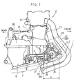
- a combination oil filter and oil cooler unit U made up of an oil filter 3 having an annular filter element 31 retained therein, an oil cooler 4 and a mounting bracket 5 positioned between the oil filter 3 and the oil cooler 4 is provided at a position of the lower casing 12 forwardly of a crank chamber 15 (Fig. 2).
- the mounting bracket 5 has a filter support 5a and a cooler support 5b both formed therein, and the oil filter 3 and the oil cooler 4 are supported by the mounting bracket 5 through the filter support 5a and the cooler support 5b, respectively.
- the filter support 5a and the cooler support 5b are in the form of flat mounting surfaces, respectively, that are parallel to each other.
- the mounting bracket 5 is formed with an oil communicating passage 5c for communicating between the oil filter 3 and the oil cooler 4.
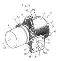
- the mounting bracket 5 has a support portion 55 to support the oil filter 3 and the oil cooler 4 and further, has a mounting base 56 to be mounted on the engine body 1 (Fig. 2).
- the support portion 55 is provided with the filter support 5a and the cooler support 5b that form respective end faces of the support portion 55.
- the mounting base 56 is formed with a plurality of, for example, four, bolt insertion holes 51. As shown in Fig. 2, by means of mounting bolts 17 inserted through the respective bolt insertion holes 51 (Fig.
- the mounting bracket 5 can be firmly secured to the engine body 1 with a mounting face 50 of the mounting base 56 held in tight contact with a front surface of the lower casing 12 of the engine body 1, i.e., a front lower portion of the crankcase CR.
- an engine oil O accumulating within an oil pan or reservoir mounted on a bottom of the lower casing 12 as shown in Fig. 2 can be supplied by the oil pump 8 so as to flow through a first oil supply passage 21 within the lower casing 12 and then through a second oil supply passage 22 within the mounting bracket 5 before it reaches the oil filter 3 through an exit port 23 of the second oil supply passage 22.
- the engine oil O flowing into the oil filter 3 as best shown in Fig. 3 passes radially inwardly through the annular filter element 31 within the oil filter 3 from an outer periphery towards an inner periphery thereof, with foreign matters such as metallic particles and/or grits consequently trapped and, hence, removed by the annular filter element 31.
- the purified engine oil O subsequently flows through the oil communicating passage 5c in the mounting bracket 5 into the oil cooler 4. After it has been cooled by the oil cooler 4, the engine oil O flows through an introducing port 25 formed in the mounting bracket 5 into an oil return passage 26 shown in Fig. 2, and then through an oil return passage 27 in the lower casing 12 towards a main gallery 28.
- the engine oil O entering the main gallery 28 is utilized to lubricate various movable component parts of the engine such as, for example, camshafts, a crankshaft, big ends of connecting rods, all not shown.
- the mounting bracket 5 has an internally threaded communicating hole 53 defined at a substantially center portion thereof and also has a plurality of, for example, three in the illustrated embodiment, perforated bosses 52 formed integrally therewith so as to protrude outwardly from an outer periphery of the mounting bracket 5.
- the oil filter 3 is positioned on a right side of the mounting bracket 5 as viewed in Fig. 3, or a left side of the motorcycle frame structure F (Fig. 1) with respect to the direction of forward travel and, has a base 32, a substantially center portion of which has holes 33 defined therein in alignment with the internally threaded communicating hole 53.
- the oil filter 3 can be secured to the mounting bracket 5 with the base 32 held in tight contact with the mounting bracket 5, by means of an externally threaded quill bolt 9 passing through the hole 33 in the base 32 of the oil filter 3 and then firmly threaded into the threaded communicating hole 53.
- the communicating passage 5c referred to hereinbefore and communicating between the oil filter 3 and the oil cooler 4 is defined by the internal bore of the quill bolt 9 and that fastening of the quill bolt 9 can be accomplished by turning a bolt head 9a of the quill bolt 9.
- the filter element 31 is carried by the base 32 of the oil filter and positioned on one side of the mounting bracket 5 remote from the oil cooler 4 and is enclosed by a generally cylindrical cap 35.
- the cap 35 has an internally threaded portion 35a defined in an inner peripheral surface thereof at a location adjacent the opening of the cap 35 and is firmly threadingly capped onto an externally threaded portion 32a, formed in an outer peripheral portion of the base 32, to thereby connect the cap 35 with the base 32.
- the cap 35 can be removed from the base 32 by undoing the cap 35 relative to the base 32.
- the oil cooler 4 positioned on a left side of the mounting bracket 5 as viewed therein, or a right side of the motorcycle frame structure F (Fig. 1) with respect to the direction of forward travel includes a generally cylindrical housing 41 having its outer peripheral portion formed with radially outwardly protruding lugs 42, equal in number to that of the perforated bosses 52 of the mounting bracket 5.
- the oil cooler 4 is of a water cooled type such that a cooling water W enter into the oil cooler 4 through an intake port 47 in an upper region thereof and can emerge outwardly through an outlet port 49 after having flowed past cooling fins 48 to cool the oil O.
- the cooling water W referred to above is supplied to the oil cooler 4 by means of a water pump (not shown) that is used to cool the internal combustion engine E (Fig. 1) in a manner known to those skilled in the art.
- both of the oil filter 3 and the oil cooler 4 are of a generally cylindrical configuration having respective longitudinal axes C3 and C4.
- the oil filter 3 and the oil cooler 4 supported by the mounting bracket 5 in the manner hereinabove described above are positioned relative to each other with their longitudinal axes C3 and C4 aligned horizontally with each other.
- the mounting base 56 having the mounting face 50 as hereinbefore described is positioned at a location offset laterally from the mutually aligned longitudinal axes C3 and C4 with the mounting face 50 held parallel to the longitudinal axes C3 and C4.
- the oil filter 3 and the oil cooler 4 do not protrude in a direction perpendicular to the plane of the mounting face 50 with the two-staged arrangement employed in the prior art, but they assume a position held in side-by-side relation with the mounting face 50 in a direction perpendicular to the mounting face 50 and, therefore, the amount of protrusion of the oil filter 3 and the oil cooler 4, shown by H in Fig. 2, can advantageously be minimized.
- the oil communicating passage 5c defined in the quill bolt 9 as discussed above with reference to Fig. 3 is positioned in alignment with the longitudinal axes C3 and C4. It is, however, to be noted that the longitudinal axes C3 and C4 may be offset relative to each other, but either parallel or at an angle to each other. Also, the mounting face 50 of the mounting base 56 integral with the mounting bracket 5 shown in Fig. 4 may not be always parallel to the longitudinal axes C3 and C4, but may be somewhat inclined relative to those longitudinal axes C3 and C4.
- the oil filter 3 is secured to the filter support 5a of the mounting bracket 5, not to the oil cooler 4.
- the oil cooler 4 is similarly secured to the cooler support 5b of the mounting bracket 5, not to the oil filter 3.
- the mounting of the oil filter 3 depends on the strength of the mounting bracket 5 and is supported regardless of the strength of the oil cooler 4.
- the housing 41 of the oil cooler 4 can be made of a light-weight material having a relatively low strength such as, for example, aluminum and, therefore, an undesirable increase of the weight of the oil cooler 4 can advantageously be suppressed.
- each of the oil filter 3 and the oil cooler 4 protrudes outwardly from the engine body 1 by a relatively small amount H comparable to the diameter of a single component part of the unit U and, accordingly, an undesirable interference of any of the oil filter 3 and the oil cooler 4 with other component parts such as, for example, exhaust tubes 2A to 2D can advantageously be avoided.
- the oil filter 3 shown in Fig. 1 is oriented laterally outwardly of the motorcycle frame structure F, the cap 35 can readily be removed in a direction laterally outwardly of the motorcycle frame structure F without being interfered with the exhaust tubes 2A to 2D and, hence, maintenance and inspection of the oil filter 3, including replacement of the oil filter element 31 (Fig. 3), can readily be accomplished without being interfered with the exhaust tubes 2A to 2D.
- the oil filter 3 and the coil cooler 4 may not be necessarily arranged in the manner described hereinbefore in which they are positioned on respective left and right sides of and in symmetrical relation to each other with respect to the mounting bracket 5, but may be arranged in a manner as shown in any one of Figs. 5 to 8.
- the oil filter 3 and the oil cooler 4 are so arranged on respective sides of the mounting bracket 4 that when viewed from front of the motorcycle, the oil filter 3 can be inclined downwardly relative to the oil cooler 4.
- the longitudinal axis C4 of the oil cooler 4 extends horizontally while the longitudinal axis C3 of the oil filter 3 lies at an angle relative to the longitudinal axis C4 and extends downwardly from the mounting bracket 5.
- the oil filter 3 assumes such a position as shown by the phantom line A in Fig. 1.
- This embodiment is particularly advantageous in that when the cap 35 in Fig. 5 is removed during maintenance, inspection or replacement of the filter element 31 within the oil filter 3, the engine oil can be collected within the cap 35 and will hardly leak to the outside.
- the oil filter 3 and the oil cooler 4 are positioned on respective sides of the mounting bracket 5, but are oriented up and down with the oil cooler 4 positioned above the oil filter 3.
- the longitudinal axes C3 and C4 of the oil filter 3 and the oil cooler 4 lie vertically.
- the third embodiment shown in and described with reference to Fig. 6 is particularly advantageous in that where no space for installation is available leftwards or rightwards of the engine body 1, the oil filter 3 and the oil cooler 4 can be secured to the engine body 1 neatly. Also, as is the case with the previously described second embodiment, an additional advantage can be appreciated that when the cap 35 is removed during maintenance, inspection or replacement of the filter element 31 within the oil filter 3, the engine oil can be collected within the cap 35 and will hardly leak to the outside.
- the oil filter 3 and the oil cooler 4 assume respective positions shown by the phantom lines B1 and B2 in Fig. 1. It is, however, to be noted that the oil filter 3 and the oil cooler 4 may be reversed in position relative to each other, i.e., with the oil filter 3 positioned above the oil cooler 4.
- the oil filter 3 is so arranged as to be oriented upwardly with the longitudinal axis C3 thereof lying vertically, but the oil cooler 4 remains as is the case with the first embodiment shown in Fig. 3, i.e., is so arranged as to be oriented horizontally with the longitudinal axis C4 thereof lying horizontally.
- the respective longitudinal axes C3 and C4 lie perpendicular to each other.
- the oil filter 3 assumes such a position as shown by the phantom line C in Fig. 1.
- the mounting bracket 5 is so designed as to be mounted on a motorcycle frame structure F through a gusset 6, not on the engine body 1, so that the oil filter 3 and the oil cooler 4 can assume respective positions on both sides of the mounting bracket 5.
- the mounting bracket 5 shown in Fig. 8 can be secured to a portion of the motorcycle frame structure F forwardly of the engine body 1.
- the combined oil filter and oil cooler unit U can be arranged at a proper position.
Landscapes
- Engineering & Computer Science (AREA)
- Mechanical Engineering (AREA)
- General Engineering & Computer Science (AREA)
- Lubrication Details And Ventilation Of Internal Combustion Engines (AREA)
- Lubrication Of Internal Combustion Engines (AREA)
Abstract
Description
Claims (10)
- A combined oil filter and oil cooler unit, which comprises:a mounting bracket adapted to be mounted on a vehicle engine or a vehicle body structure carrying the vehicle engine and having a filter support and a cooler support defined therein;an oil filter supported by the filter support of the mounting bracket; andan oil cooler supported by the cooler support of the mounting bracket.
- The combined oil filter and oil cooler unit as claimed in Claim 1, wherein the bracket has an oil communicating passage defined therein for communicating between the oil filter and the oil cooler.
- The combined oil filter and oil cooler unit as claimed in Claim 2, wherein the oil filter and the oil cooler are arranged on respective opposite sides of the mounting bracket.
- The combined oil filter and oil cooler unit as claimed in Claim 3, wherein the filter support and the cooler support have a filter support face and a cooler support face, which are parallel to each other, wherein the oil filter and the oil cooler supported respectively by the filter support face and the cooler support face.
- The combined oil filter and oil cooler unit as claimed in Claim 4, wherein the oil filter and the oil cooler have respective longitudinal axes substantially aligned with each other, and the coil communicating passage is arranged substantially coaxially on the respective longitudinal axes of the oil filter and the oil cooler.
- The combined oil filter and oil cooler unit as claimed in Claim 1, wherein the oil filter and the oil cooler have respective longitudinal axes lying substantially parallel to each other and wherein the mounting bracket has a mounting face through which the mounting bracket is secured to the engine or the vehicle body structure, said mounting face being located at a position offset from the respective longitudinal axes of the oil filter and the oil cooler.
- The combined oil filter and oil cooler unit as claimed in Claim 6, wherein the respective longitudinal axes of the oil filter and the oil cooler extend horizontally.
- The combined oil filter and oil cooler unit as claimed in Claim 6, wherein the respective longitudinal axes of the oil filter and the oil cooler extend vertically with the oil cooler positioned above the oil filter.
- The combined oil filter and oil cooler unit as claimed in Claim 1, wherein the oil cooler has a longitudinal axis extending horizontally and the oil filter has a longitudinal axis extending inclined downwardly relative to the oil cooler.
- The combined oil filter and oil cooler unit as claimed in Claim 1, wherein the oil filter and the oil cooler have respective longitudinal axes lying perpendicular to each other.
Applications Claiming Priority (2)
| Application Number | Priority Date | Filing Date | Title |
|---|---|---|---|
| JP2003283856A JP3917570B2 (en) | 2003-07-31 | 2003-07-31 | Oil filter / oil cooler unit |
| JP2003283856 | 2003-07-31 |
Publications (2)
| Publication Number | Publication Date |
|---|---|
| EP1503050A2 true EP1503050A2 (en) | 2005-02-02 |
| EP1503050A3 EP1503050A3 (en) | 2005-07-20 |
Family
ID=33535708
Family Applications (1)
| Application Number | Title | Priority Date | Filing Date |
|---|---|---|---|
| EP04017743A Withdrawn EP1503050A3 (en) | 2003-07-31 | 2004-07-27 | Combined oil filter and oil cooler unit |
Country Status (3)
| Country | Link |
|---|---|
| US (1) | US20050023200A1 (en) |
| EP (1) | EP1503050A3 (en) |
| JP (1) | JP3917570B2 (en) |
Cited By (4)
| Publication number | Priority date | Publication date | Assignee | Title |
|---|---|---|---|---|
| EP2146060A1 (en) * | 2008-06-18 | 2010-01-20 | Honda Motor Co., Ltd. | Engine oil filter system |
| EP2154342A1 (en) * | 2008-08-14 | 2010-02-17 | Mann + Hummel Gmbh | Oil cooler-oil pump device for a combustion engine |
| EP2177724A1 (en) * | 2008-10-18 | 2010-04-21 | Mahle International GmbH | Filter device with a locking device |
| FR2989994A1 (en) * | 2012-04-27 | 2013-11-01 | Peugeot Citroen Automobiles Sa | Accessory support for supporting e.g. alternator, by combustion engine in power plant, has channel intended to be connected to lubrication circuit of engine, where channel includes bend for orientation of oil pressure sensor along engine |
Families Citing this family (16)
| Publication number | Priority date | Publication date | Assignee | Title |
|---|---|---|---|---|
| JP4548351B2 (en) * | 2006-01-25 | 2010-09-22 | トヨタ自動車株式会社 | Oil cooler mounting structure |
| US7992667B2 (en) * | 2006-08-08 | 2011-08-09 | David Wayne Rennie | Oil cooling and filtering system, kit and apparatus |
| US7516727B2 (en) | 2006-09-21 | 2009-04-14 | Kawasaki Jukogyo Kabushiki Kaisha | Vehicle combustion engine |
| JP4889541B2 (en) * | 2007-03-28 | 2012-03-07 | 本田技研工業株式会社 | Internal combustion engine for vehicles |
| KR200461391Y1 (en) | 2010-01-05 | 2012-07-13 | 주식회사 세원 | oil filter assembly |
| US8911620B2 (en) * | 2010-11-29 | 2014-12-16 | Vesa S. Silegren | Universal spin-on oil filter adapter |
| US9157399B2 (en) * | 2011-05-05 | 2015-10-13 | Hamilton Sundstrand Corporation | Fuel filter adapter |
| US9587532B1 (en) * | 2012-03-22 | 2017-03-07 | Vinh Au | Oil, coolant, and exahust gas circulation system, elements and kits |
| WO2015004758A1 (en) | 2013-07-10 | 2015-01-15 | 川崎重工業株式会社 | Vehicle engine lubrication system |
| CN103397924B (en) * | 2013-08-06 | 2016-03-16 | 潍柴动力股份有限公司 | A kind of engine oil control body |
| JP6695931B2 (en) * | 2018-07-06 | 2020-05-20 | 本田技研工業株式会社 | Internal combustion engine |
| JP7392555B2 (en) * | 2020-04-01 | 2023-12-06 | マツダ株式会社 | Engine oil cooler vibration reduction structure |
| US12564801B2 (en) * | 2021-03-18 | 2026-03-03 | Volvo Truck Corporation | Oil filter with two filtrate outlets and vehicle lubrication circuit |
| CN113550808B (en) * | 2021-08-18 | 2022-11-29 | 河南柴油机重工有限责任公司 | Throttle control lubricating system |
| CN115839461B (en) * | 2022-12-05 | 2025-07-25 | 袁鑫工程顾问(上海)事务所 | Support method for support structure and support structure |
| US12078090B1 (en) | 2024-02-29 | 2024-09-03 | Skyward Automotive Products LLC | Oil filter housing and assembly |
Family Cites Families (4)
| Publication number | Priority date | Publication date | Assignee | Title |
|---|---|---|---|---|
| US2068395A (en) * | 1932-07-21 | 1937-01-19 | Michiana Products Corp | Filter and heat exchanger |
| FR2708038A1 (en) * | 1993-07-23 | 1995-01-27 | Peugeot | Assembly for the lubrication circuit of a motor vehicle internal combustion engine |
| US6182616B1 (en) * | 1997-12-24 | 2001-02-06 | Isuzu Motors Limited | Cooling water circulating structure for engines |
| DE10012461A1 (en) * | 2000-03-15 | 2001-09-20 | Mahle Filtersysteme Gmbh | Oil filter for cleaning lubricating oil has annular filter insert separating clean side from input side |
-
2003
- 2003-07-31 JP JP2003283856A patent/JP3917570B2/en not_active Expired - Fee Related
-
2004
- 2004-07-27 EP EP04017743A patent/EP1503050A3/en not_active Withdrawn
- 2004-07-28 US US10/900,949 patent/US20050023200A1/en not_active Abandoned
Cited By (6)
| Publication number | Priority date | Publication date | Assignee | Title |
|---|---|---|---|---|
| EP2146060A1 (en) * | 2008-06-18 | 2010-01-20 | Honda Motor Co., Ltd. | Engine oil filter system |
| US8347845B2 (en) | 2008-06-18 | 2013-01-08 | Honda Motor Co., Ltd. | Engine oil filter and cooling system |
| EP2154342A1 (en) * | 2008-08-14 | 2010-02-17 | Mann + Hummel Gmbh | Oil cooler-oil pump device for a combustion engine |
| US8336515B2 (en) | 2008-08-14 | 2012-12-25 | Mann + Hummel Gmbh | Oil cooler oil pump assembly for an internal combustion engine |
| EP2177724A1 (en) * | 2008-10-18 | 2010-04-21 | Mahle International GmbH | Filter device with a locking device |
| FR2989994A1 (en) * | 2012-04-27 | 2013-11-01 | Peugeot Citroen Automobiles Sa | Accessory support for supporting e.g. alternator, by combustion engine in power plant, has channel intended to be connected to lubrication circuit of engine, where channel includes bend for orientation of oil pressure sensor along engine |
Also Published As
| Publication number | Publication date |
|---|---|
| JP2005048725A (en) | 2005-02-24 |
| EP1503050A3 (en) | 2005-07-20 |
| US20050023200A1 (en) | 2005-02-03 |
| JP3917570B2 (en) | 2007-05-23 |
Similar Documents
| Publication | Publication Date | Title |
|---|---|---|
| US20050023200A1 (en) | Combined oil filter and oil cooler unit | |
| US6543405B2 (en) | Modular engine architecture | |
| CA2889282C (en) | An air flow guide for an internal combustion engine | |
| US11214139B2 (en) | Motorcycle | |
| JP5932574B2 (en) | Water-cooled internal combustion engine for vehicles | |
| US7318405B2 (en) | Engine for vehicle | |
| CN101608561B (en) | Engine oil filter system | |
| US20090218169A1 (en) | Engine lubrication system | |
| US7516727B2 (en) | Vehicle combustion engine | |
| US7717100B2 (en) | Breather structure of engine | |
| US20150114327A1 (en) | Engine and straddle-type vehicle including the same | |
| US8307791B2 (en) | Four-cycle air-oil cooled engine, and vehicle incorporating same | |
| US6904884B2 (en) | Balance device for engines | |
| US20080083398A1 (en) | Breather assembly for an internal combustion engine | |
| JP4632307B2 (en) | Oil filter device and motorcycle equipped with oil filter device | |
| JP2002256838A (en) | Engine breather structure | |
| CN109209552B (en) | Crankshaft for internal combustion engine | |
| JP3232924B2 (en) | Motorcycle engine piston cooling structure | |
| JP4851899B2 (en) | Vehicle engine | |
| JP3289523B2 (en) | Lubricating oil passage structure of internal combustion engine | |
| JP4605607B2 (en) | Cooling water passage structure for water-cooled engine | |
| KR200204923Y1 (en) | Oil filter case for oil cooling | |
| JP4718406B2 (en) | Engine lubrication equipment | |
| JPH0144889B2 (en) | ||
| JP4636551B2 (en) | Backpack type air blower equipped with 4-cycle engine |
Legal Events
| Date | Code | Title | Description |
|---|---|---|---|
| PUAI | Public reference made under article 153(3) epc to a published international application that has entered the european phase |
Free format text: ORIGINAL CODE: 0009012 |
|
| 17P | Request for examination filed |
Effective date: 20040727 |
|
| AK | Designated contracting states |
Kind code of ref document: A2 Designated state(s): AT BE BG CH CY CZ DE DK EE ES FI FR GB GR HU IE IT LI LU MC NL PL PT RO SE SI SK TR |
|
| AX | Request for extension of the european patent |
Extension state: AL HR LT LV MK |
|
| PUAL | Search report despatched |
Free format text: ORIGINAL CODE: 0009013 |
|
| AK | Designated contracting states |
Kind code of ref document: A3 Designated state(s): AT BE BG CH CY CZ DE DK EE ES FI FR GB GR HU IE IT LI LU MC NL PL PT RO SE SI SK TR |
|
| AX | Request for extension of the european patent |
Extension state: AL HR LT LV MK |
|
| RIC1 | Information provided on ipc code assigned before grant |
Ipc: 7F 01M 11/03 B Ipc: 7F 01M 5/00 B Ipc: 7F 01M 11/00 B Ipc: 7F 01M 1/10 A |
|
| STAA | Information on the status of an ep patent application or granted ep patent |
Free format text: STATUS: THE APPLICATION HAS BEEN WITHDRAWN |
|
| 18W | Application withdrawn |
Effective date: 20051215 |