EP1502893A2 - Electronic safety system for escalators - Google Patents
Electronic safety system for escalators Download PDFInfo
- Publication number
- EP1502893A2 EP1502893A2 EP20040019618 EP04019618A EP1502893A2 EP 1502893 A2 EP1502893 A2 EP 1502893A2 EP 20040019618 EP20040019618 EP 20040019618 EP 04019618 A EP04019618 A EP 04019618A EP 1502893 A2 EP1502893 A2 EP 1502893A2
- Authority
- EP
- European Patent Office
- Prior art keywords
- bus
- safety
- passenger conveyor
- safety system
- recited
- Prior art date
- Legal status (The legal status is an assumption and is not a legal conclusion. Google has not performed a legal analysis and makes no representation as to the accuracy of the status listed.)
- Granted
Links
- 238000004891 communication Methods 0.000 claims abstract description 24
- 238000007689 inspection Methods 0.000 claims description 10
- 238000012423 maintenance Methods 0.000 claims description 7
- 230000006870 function Effects 0.000 claims description 2
- 238000000034 method Methods 0.000 description 9
- 238000009434 installation Methods 0.000 description 4
- 230000008901 benefit Effects 0.000 description 3
- 238000012986 modification Methods 0.000 description 3
- 230000004048 modification Effects 0.000 description 3
- 238000012544 monitoring process Methods 0.000 description 3
- 230000000694 effects Effects 0.000 description 2
- 238000004519 manufacturing process Methods 0.000 description 2
- 230000000737 periodic effect Effects 0.000 description 2
- 230000008569 process Effects 0.000 description 2
- 238000012360 testing method Methods 0.000 description 2
- 230000015556 catabolic process Effects 0.000 description 1
- 230000008859 change Effects 0.000 description 1
- 125000004122 cyclic group Chemical group 0.000 description 1
- 238000006731 degradation reaction Methods 0.000 description 1
- 238000013461 design Methods 0.000 description 1
- 230000009977 dual effect Effects 0.000 description 1
- 230000006872 improvement Effects 0.000 description 1
- 230000003993 interaction Effects 0.000 description 1
- 230000005055 memory storage Effects 0.000 description 1
- 230000008439 repair process Effects 0.000 description 1
Images
Classifications
-
- B—PERFORMING OPERATIONS; TRANSPORTING
- B66—HOISTING; LIFTING; HAULING
- B66B—ELEVATORS; ESCALATORS OR MOVING WALKWAYS
- B66B29/00—Safety devices of escalators or moving walkways
- B66B29/005—Applications of security monitors
-
- B—PERFORMING OPERATIONS; TRANSPORTING
- B66—HOISTING; LIFTING; HAULING
- B66B—ELEVATORS; ESCALATORS OR MOVING WALKWAYS
- B66B27/00—Indicating operating conditions of escalators or moving walkways
Definitions
- a typical passenger conveyor such as an escalator or moving walk, includes a truss, a plurality of sequentially connected treadplates traveling through a closed loop path within the truss, and a machine for driving the treadplates.
- Escalators and moving walks include devices such as sensors for monitoring speed, sensors for detecting missing treadplates, devices for monitoring wear; actuators for utilizing special purpose devices and output devices, such as traffic lights.
- Each of these devices includes a combination of interface devices, i.e., sensors, switches or actuators, that are connected to a central control.
- interface devices i.e., sensors, switches or actuators, that are connected to a central control.
- typical passenger conveyers include a safety system that monitors and responds to each sensor.
- Safety Chain is a serial circuit of the switches and contacts.
- the Safety Chain operates relays (or contactors) that handle the power to the escalator motor. An operation of any contact within the chain will disconnect the motor or drive from the main power supply.
- the serial connections of the contacts and the bridging for inspection leads to a long chain which requires higher voltages to minimize the effects of voltage losses along the chain.
- An escalator system designed according to this invention improves inspection and diagnostic work, promotes safe escalator operation, and enables safe degradation when an unsafe condition is detected.
- the safety system includes a communications bus which facilitates the exchange of control and data signals between a microprocessor based safety controller or "bus master".
- bus master a microprocessor based safety controller
- Various other components including bus nodes designed to interface with sensors, contacts, and switches along with detectors, components, and other safety equipment ensure the safe operation of the escalator system.
- the software controlled bus master operates a communications bus which has bus nodes throughout the entire escalator system.
- the bus nodes are periodically polled to ascertain the status of the sensors, contacts, and switches connected to the bus nodes.
- the microprocessor may operate in one of several different modes such as maintenance, inspection, normal operations, degraded operations, and emergency operations.
- the bus master When appropriate, the bus master generates output signals to the escalator control system and the escalator drive and brake system.
- the bus master If an unsafe condition occurs, the bus master generates the appropriate outputs to be conveyed to the escalator control and drive systems.
- the safety controller may activate devices to arrest the escalator's motion.
- the bus master and associated components provide an electronic safety system which can be centrally managed, greatly improves installation time, quality, manufacturing costs, and operational characteristics.
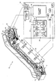
- the Figure schematically illustrates an electronic safety system for an escalator system designed according to this invention.
- the Figure illustrates an escalator system 10. It should become apparent in the ensuing description that the invention is applicable to other passenger conveyors, such as moving walks.
- the escalator system 10 generally includes a truss 12 extending between a lower landing 14 and an upper landing 16.
- a plurality of sequentially connected treadplates 18 are connected to a step chain 20 and travel through a closed loop path within the truss 12.
- a pair of balustrades 22 have handrails 24.
- a machine 26 drive the treadplates 18 and handrails 24.
- the machine 26 is typically located in a machine space 28 under the upper landing 16.
- An electronic safety system 30 includes an escalator controller 32 that communicates with an electronic safety controller such as a bus master 34, an escalator power system 36, and a drive and brake system 38, which operates the machine 26.
- an electronic safety controller such as a bus master 34, an escalator power system 36, and a drive and brake system 38, which operates the machine 26.
- the bus master 34 communicates over a bus 40 with a plurality of bus nodes 42.
- the bus master 34 is preferably implemented using a communications protocol known as a Controller Area Network (CAN) bus.
- CAN Controller Area Network
- Each bus node 42 interfaces with at least one sensor device 44.
- the sensor devices 44 such as sensors, switches, contacts or other input or output devices are distributed throughout the escalator system 10.
- the sensor devices 44 preferably include such sensors as a speed sensor for the treadplates 18, a sensor to detect missing treadplates 18, a limit switch to detect excessive wear of the step chain 20 and treadplates 18, and a sensor to monitor the speed of the handrails 24.
- Also among the sensor devices 44 are, for example, a switch in each landing 14, 16, to detect the presence of a passenger and to trigger a change in speed of the treadplates 18, and a switch in each landing 14,16, to actuate the operation of a wheelchair platform embedded into the treadplates 18.
- sensor devices 44 such as sensors 44', which monitor the status of the electronic safety system 30, also preferably communicate over the bus 40.
- non-safety components such as a traffic light or an operational panel on the bus to save installation effort.
- the bus master 34 continuously processes the data from the bus nodes 42 which communicate with the sensor devices 44. Under predetermined conditions the bus master 34 provides a signal to the escalator controller 32 through an input/output connection 35. The escalator controller 32 sends an appropriate control signal to the escalator drive and brake system 38 to carry out the appropriate measure, e.g., switch off the escalator drive system, activate the brake and generate a detailed diagnostic.
- the appropriate measure e.g., switch off the escalator drive system
- the bus nodes 42 are located along the escalator system 10 to communicate with the variety of sensor devices 44 that send data to the bus node 42.
- the data gathering sensor devices 44 may be wired to a bus node 42 in parallel or in series or in a combination of the two depending on the quantity of sensors, contacts or switches being monitored by a particular bus node 42. However it is desirable to have as many sensors, contacts or switches wired in parallel with each other so that when the bus node 42 receives an input from one of these devices, the bus node 42 will know which particular device is sending information to it.
- This architecture allows the software program executing on the bus master 34 to pinpoint the source and condition causing the data signal. This is a significant advantage compared to a serial wiring circuit where the software program can only identify the data signal at a circuit level.
- Power is delivered to the sensor devices 44 by the bus nodes 42. Due to the short distances between the bus nodes 42 and the sensor devices 44, a lower voltage can be used, in this case 24Vdc.
- the sensor devices 44 can be automatically tested by the software program. This feature obviates the need for manual checks and reduces inspection times. It also allows a service routine to be expanded in time and focus on other critical maintenance areas.
- the bus master 34 determines whether an unsafe condition exists based upon known logic.
- bus 40 design is very flexible and that additional bus nodes 42 may be added or dropped as needed with the appropriate changes made in software to process the new data. Also some nodes 42 may have spare input/output capacity so that they may interface with additional sensors 44.
- the modularity of the bus 40 allows these types of modifications to be made in an improved manner over the prior art.
- the bus master 34 preferably includes a microprocessor 48 that internally communicates over a microprocessor system bus 50 with a read-only memory (ROM) 52, a random access memory (RAM) 54, a power back up unit (BATT) 56, a logic unit 58 and an input/output communications port (I/O) 60.
- ROM read-only memory
- RAM random access memory
- BATT power back up unit
- I/O input/output communications port
- ROM read-only memory
- RAM random access memory
- BATT power back up unit
- I/O input/output communications port
- Each of these can be realized with conventional components, custom integrated circuits, custom software or a combination of the three. Given this description, those skilled in the art will be able to choose from among the various options. It should be noted that although in this embodiment a ROM 52 is used for a non-volatile memory, other types of non-volatile memory such as EPROM may be used.
- the microprocessor 48 executes a software program stored in the
- the volatile memory may, for example only, be designed as Flash ROM, so that software updates may be downloaded from a maintenance computer PC (not shown). This method may be used to effect code or data changes or both.
- the volatile memory storage device in the disclosed embodiment is the ROM 52, other storage devices may include a hard drive, CD ROM, DVD, RAM, ROM or other optically readable storage, magnetic storage or integrated circuit.
- the bus master 34 communicates with the bus nodes 42 over the bus 40 through I/O port 60.
- the bus 40 may be a single bus (bus A) or a dual redundant bus (bus A and bus B, not shown).
- bus master 34 can communicate with any of the bus nodes 42 over either bus A or bus B (not shown) as well known to those skilled in the art.
- bus A bus
- bus B bus B
- a single bus and single microprocessor are illustrated in the disclosed embodiment, other configurations will benefit from the present invention as described in more detail in United States Patent 6,173,814 entitled ELECTRONIC SAFETY SYSTEM FOR ELEVATORS which is incorporated by reference in its entirety into this description.
- Communications between the bus master 34 and the bus nodes 42 are preferably scheduled by software to communicate with every bus node 42 periodically regardless of whether data is being provided by the bus node 42.
- Periodic communications allows the software running on the bus master 34 to positively reaffirm that the communications through the bus 40 to the bus nodes 42, are operational.
- These periodic messages include status information from hardware checks performed at each bus node 42.
- each bus node 42 is polled twice on the same data set, and the data sets are compared by the software program to make sure they are identical. If the data sets do not match, the software program in ROM 52 polls the bus node 42 again to determine its reliability. The software program may determine the mismatched data was a one time anomaly or it may determine that there is a communications failure which needs repair. The software program in ROM 52 may communicate with the escalator controller 32 to shut down the escalator system 10 if it determines, that communications with the bus nodes 42 have become unreliable.
- the bus master 34 directly communicates with the drive and brake system 38 through a redundant communication relay 62. The bus master 34 can thereby immediately shut down the escalator system 10 should the escalator controller 32 fail.
- the software program preferably runs in various modes such as inspection and maintenance, normal operations and emergency operations. It performs various routines or calls such as polling the bus nodes 42 for communication status and data.
- the program also outputs control signals and data to the escalator controller 32 and drive and brake system 38.
- Bus polling is implemented by the cyclic interaction of the master, in this case the bus master 34, with its slaves, in this case the bus nodes 42.
- Various schemes may be implemented to detect failures of the bus 40.
- One example is a timeout, where the bus master 34 presumes that the bus node 42 has failed if it does not respond to a communication from the bus master 34 within a certain predetermined amount of time.
- Another method is that each message transmitted on the bus 40 is tagged with an ID number in an increasing order. If a message ID is received by the bus master 34 out of order, it determines that a message has been lost or has failed to have been transmitted. Under such conditions, the bus master 34 determines that a failure has occurred.
- An echo technique may also be used wherein the bus master 34 expects an acknowledgement for each and every communications message put on the bus from the respective bus node 42 to which it is addressed. If the bus master 34 does not receive an acknowledgement from the targeted bus node 42, the bus master 34 assumes the node 42 has failed.
- each bus node 42 monitors the bus 40 to see if the sent bit is present on the bus 40. Once the bus node 42 realizes that the transmitted message is not being communicated to the bus master 34, then the bus node 42 can report a failure to the bus master 34.
- a bit stuffing technique may also be used to verify the integrity of messages wherein, based on a pre-determined algorithm, a transmitter inserts stuffed bits of opposite logic after a certain number of bits with the same logic level have been transmitted.
- Another technique is a CRC Checksum wherein a checksum is inserted in each message to verify message integrity.
- the message may also be formatted so that each message must fit into a pre-determined format of bit length and/or fields.
- An acknowledge check may also be implemented wherein at least one receiver has to acknowledge the reception of any transmitted message.
- the software can temporarily install a "software bridge" in the safety chain so that various sensors, contacts or switches can be isolated for testing.
- hardware wiring is no longer necessary to bridge a sensor, contact or switch.
- An important improvement over the prior art is that the 'software bridges' can be removed automatically by the program either using a time function or when the software program exits the inspection mode and returns to the normal operations mode. In either case, an operator no longer is needed to insert and subsequently remove all of the hardware wiring or mechanical bridges for inspection or maintenance work.
Landscapes
- Escalators And Moving Walkways (AREA)
Abstract
Description
- This invention relates to a passenger conveyor system, and more particularly to a safety system including a communication bus that connects safety related components. A typical passenger conveyor, such as an escalator or moving walk, includes a truss, a plurality of sequentially connected treadplates traveling through a closed loop path within the truss, and a machine for driving the treadplates.
- Escalators and moving walks include devices such as sensors for monitoring speed, sensors for detecting missing treadplates, devices for monitoring wear; actuators for utilizing special purpose devices and output devices, such as traffic lights. Each of these devices includes a combination of interface devices, i.e., sensors, switches or actuators, that are connected to a central control. To assure the continued operation of the sensors typical passenger conveyers include a safety system that monitors and responds to each sensor.
- Conventional escalator safety systems are implemented using a Safety Chain which is a serial circuit of the switches and contacts. The Safety Chain operates relays (or contactors) that handle the power to the escalator motor. An operation of any contact within the chain will disconnect the motor or drive from the main power supply. The serial connections of the contacts and the bridging for inspection leads to a long chain which requires higher voltages to minimize the effects of voltage losses along the chain.
- Because the Safety Chain is wired in serial, a failure cannot be specifically identified. During maintenance and inspection, it is sometimes necessary to include bridges in the Safety Chain by hand for testing and error searching. Manual installation and removal of the bridges is time consuming and labor intensive. Further, the serial connection renders remote checking difficult:
- Therefore it has been determined that a need exists ior an improved safety system which lowers part count and manufacturing costs, all while improving operability.
- An escalator system designed according to this invention improves inspection and diagnostic work, promotes safe escalator operation, and enables safe degradation when an unsafe condition is detected. The safety system includes a communications bus which facilitates the exchange of control and data signals between a microprocessor based safety controller or "bus master". Various other components including bus nodes designed to interface with sensors, contacts, and switches along with detectors, components, and other safety equipment ensure the safe operation of the escalator system.
- The software controlled bus master operates a communications bus which has bus nodes throughout the entire escalator system. The bus nodes are periodically polled to ascertain the status of the sensors, contacts, and switches connected to the bus nodes. The microprocessor may operate in one of several different modes such as maintenance, inspection, normal operations, degraded operations, and emergency operations. When appropriate, the bus master generates output signals to the escalator control system and the escalator drive and brake system.
- If an unsafe condition occurs, the bus master generates the appropriate outputs to be conveyed to the escalator control and drive systems. The safety controller may activate devices to arrest the escalator's motion. The bus master and associated components provide an electronic safety system which can be centrally managed, greatly improves installation time, quality, manufacturing costs, and operational characteristics.
- The various features and advantages of this invention will become apparent to those skilled in the art from the following detailed description of the currently preferred embodiment. The drawings that accompany the detailed description can be briefly described as follows.
- The Figure schematically illustrates an electronic safety system for an escalator system designed according to this invention.
- The Figure illustrates an
escalator system 10. It should become apparent in the ensuing description that the invention is applicable to other passenger conveyors, such as moving walks. Theescalator system 10 generally includes atruss 12 extending between alower landing 14 and anupper landing 16. A plurality of sequentially connected treadplates 18 are connected to astep chain 20 and travel through a closed loop path within thetruss 12. A pair ofbalustrades 22 havehandrails 24. Amachine 26 drive the treadplates 18 andhandrails 24. Themachine 26 is typically located in amachine space 28 under theupper landing 16. - An
electronic safety system 30 includes anescalator controller 32 that communicates with an electronic safety controller such as abus master 34, anescalator power system 36, and a drive andbrake system 38, which operates themachine 26. - The
bus master 34 communicates over abus 40 with a plurality ofbus nodes 42. Thebus master 34 is preferably implemented using a communications protocol known as a Controller Area Network (CAN) bus. - Each
bus node 42 interfaces with at least onesensor device 44. Thesensor devices 44, such as sensors, switches, contacts or other input or output devices are distributed throughout theescalator system 10. Thesensor devices 44 preferably include such sensors as a speed sensor for the treadplates 18, a sensor to detect missing treadplates 18, a limit switch to detect excessive wear of thestep chain 20 and treadplates 18, and a sensor to monitor the speed of thehandrails 24. Also among thesensor devices 44 are, for example, a switch in eachlanding landing other sensor devices 44 such as sensors 44', which monitor the status of theelectronic safety system 30, also preferably communicate over thebus 40. In addition to the safety devices that are connected to the safety bus it is possible to connect non-safety components such as a traffic light or an operational panel on the bus to save installation effort. - The
bus master 34 continuously processes the data from thebus nodes 42 which communicate with thesensor devices 44. Under predetermined conditions thebus master 34 provides a signal to theescalator controller 32 through an input/output connection 35. Theescalator controller 32 sends an appropriate control signal to the escalator drive andbrake system 38 to carry out the appropriate measure, e.g., switch off the escalator drive system, activate the brake and generate a detailed diagnostic. - The
bus nodes 42 are located along theescalator system 10 to communicate with the variety ofsensor devices 44 that send data to thebus node 42. The datagathering sensor devices 44 may be wired to abus node 42 in parallel or in series or in a combination of the two depending on the quantity of sensors, contacts or switches being monitored by aparticular bus node 42. However it is desirable to have as many sensors, contacts or switches wired in parallel with each other so that when thebus node 42 receives an input from one of these devices, thebus node 42 will know which particular device is sending information to it. This architecture allows the software program executing on thebus master 34 to pinpoint the source and condition causing the data signal. This is a significant advantage compared to a serial wiring circuit where the software program can only identify the data signal at a circuit level. - Power is delivered to the
sensor devices 44 by thebus nodes 42. Due to the short distances between thebus nodes 42 and thesensor devices 44, a lower voltage can be used, in this case 24Vdc. - Importantly, the
sensor devices 44 can be automatically tested by the software program. This feature obviates the need for manual checks and reduces inspection times. It also allows a service routine to be expanded in time and focus on other critical maintenance areas. Thebus master 34 determines whether an unsafe condition exists based upon known logic. - It will be appreciated by those skilled in the art that the
bus 40 design is very flexible and thatadditional bus nodes 42 may be added or dropped as needed with the appropriate changes made in software to process the new data. Also somenodes 42 may have spare input/output capacity so that they may interface withadditional sensors 44. The modularity of thebus 40 allows these types of modifications to be made in an improved manner over the prior art. - The
bus master 34 preferably includes amicroprocessor 48 that internally communicates over amicroprocessor system bus 50 with a read-only memory (ROM) 52, a random access memory (RAM) 54, a power back up unit (BATT) 56, alogic unit 58 and an input/output communications port (I/O) 60. Each of these can be realized with conventional components, custom integrated circuits, custom software or a combination of the three. Given this description, those skilled in the art will be able to choose from among the various options. It should be noted that although in this embodiment aROM 52 is used for a non-volatile memory, other types of non-volatile memory such as EPROM may be used. Themicroprocessor 48 executes a software program stored in theROM 52. TheROM 52 also contains tables of data for the particular escalator installation. - The volatile memory may, for example only, be designed as Flash ROM, so that software updates may be downloaded from a maintenance computer PC (not shown). This method may be used to effect code or data changes or both. Although the volatile memory storage device in the disclosed embodiment is the
ROM 52, other storage devices may include a hard drive, CD ROM, DVD, RAM, ROM or other optically readable storage, magnetic storage or integrated circuit. - The
bus master 34 communicates with thebus nodes 42 over thebus 40 through I/O port 60. Thebus 40 may be a single bus (bus A) or a dual redundant bus (bus A and bus B, not shown). Thus, thebus master 34 can communicate with any of thebus nodes 42 over either bus A or bus B (not shown) as well known to those skilled in the art. Although, a single bus and single microprocessor are illustrated in the disclosed embodiment, other configurations will benefit from the present invention as described in more detail in United States Patent 6,173,814 entitled ELECTRONIC SAFETY SYSTEM FOR ELEVATORS which is incorporated by reference in its entirety into this description. - Communications between the
bus master 34 and thebus nodes 42 are preferably scheduled by software to communicate with everybus node 42 periodically regardless of whether data is being provided by thebus node 42. Periodic communications allows the software running on thebus master 34 to positively reaffirm that the communications through thebus 40 to thebus nodes 42, are operational. These periodic messages include status information from hardware checks performed at eachbus node 42. - In one embodiment of a normal operational mode, each
bus node 42 is polled twice on the same data set, and the data sets are compared by the software program to make sure they are identical. If the data sets do not match, the software program inROM 52 polls thebus node 42 again to determine its reliability. The software program may determine the mismatched data was a one time anomaly or it may determine that there is a communications failure which needs repair. The software program inROM 52 may communicate with theescalator controller 32 to shut down theescalator system 10 if it determines, that communications with thebus nodes 42 have become unreliable. In another embodiment, thebus master 34 directly communicates with the drive andbrake system 38 through aredundant communication relay 62. Thebus master 34 can thereby immediately shut down theescalator system 10 should theescalator controller 32 fail. - The software program preferably runs in various modes such as inspection and maintenance, normal operations and emergency operations. It performs various routines or calls such as polling the
bus nodes 42 for communication status and data. The program also outputs control signals and data to theescalator controller 32 and drive andbrake system 38. - Bus polling is implemented by the cyclic interaction of the master, in this case the
bus master 34, with its slaves, in this case thebus nodes 42. Various schemes may be implemented to detect failures of thebus 40. One example is a timeout, where thebus master 34 presumes that thebus node 42 has failed if it does not respond to a communication from thebus master 34 within a certain predetermined amount of time. Another method is that each message transmitted on thebus 40 is tagged with an ID number in an increasing order. If a message ID is received by thebus master 34 out of order, it determines that a message has been lost or has failed to have been transmitted. Under such conditions, thebus master 34 determines that a failure has occurred. - An echo technique may also be used wherein the
bus master 34 expects an acknowledgement for each and every communications message put on the bus from therespective bus node 42 to which it is addressed. If thebus master 34 does not receive an acknowledgement from the targetedbus node 42, thebus master 34 assumes thenode 42 has failed. - In a bit monitoring scheme, each
bus node 42 monitors thebus 40 to see if the sent bit is present on thebus 40. Once thebus node 42 realizes that the transmitted message is not being communicated to thebus master 34, then thebus node 42 can report a failure to thebus master 34. A bit stuffing technique may also be used to verify the integrity of messages wherein, based on a pre-determined algorithm, a transmitter inserts stuffed bits of opposite logic after a certain number of bits with the same logic level have been transmitted. - Another technique is a CRC Checksum wherein a checksum is inserted in each message to verify message integrity. The message may also be formatted so that each message must fit into a pre-determined format of bit length and/or fields. An acknowledge check may also be implemented wherein at least one receiver has to acknowledge the reception of any transmitted message. Many of these communication techniques are implemented in the CAN bus standard, however the additional techniques described herein above are preferably implemented to increase communications efficiency/and reliability.
- In an inspection mode the software can temporarily install a "software bridge" in the safety chain so that various sensors, contacts or switches can be isolated for testing. Thus hardware wiring is no longer necessary to bridge a sensor, contact or switch. An important improvement over the prior art is that the 'software bridges' can be removed automatically by the program either using a time function or when the software program exits the inspection mode and returns to the normal operations mode. In either case, an operator no longer is needed to insert and subsequently remove all of the hardware wiring or mechanical bridges for inspection or maintenance work.
- Given this description, those skilled in the art will be able to develop the necessary software code to achieve the results provided by this invention.
- The foregoing description is exemplary rather than defined by the limitations within. Many modifications and variations of the present invention are possible in light of the above teachings. The preferred embodiments of this invention have been disclosed, however, one of ordinary skill in the art would recognize that certain modifications would come within the scope of this invention. It is, therefore, to be understood that within the scope of the appended claims, the invention may be practiced otherwise than as specifically described. For that reason the following claims should be studied to determine the true scope and content of this invention.
Claims (13)
- A passenger conveyor safety system (30) comprising:characterized in thata control unit (32); anda safety controller (34) in communication with said control unit (32); saidsafety controller (34) communicates over a bus (40) with a plurality of bus nodes (42), each of said bus nodes (42) receiving data from at least one sensor (44), said safety controller (34) operable to send a signal to said control unit (43) in response to said data received from said plurality of bus nodes (42),
said at least one sensor includes a plurality of sensors (44) communicating with a common bus node (42). - A passenger conveyor safety system (30) comprising:characterized in thata control unit (32); and a safety controller (34) in communication with said control unit (32), said safety controller (34) communicates over a bus (40) with a plurality of bus nodes (42), each of said bus nodes (42) receiving data from at least one sensor (44), said safety controller (34) operable to send a signal to said control unit (32) in response to said data received from said plurality of bus nodes (42),
said bus nodes (42) are periodically polled by the safety controller (34). - A passenger conveyor safety system as recited in claim 1 or 2, wherein said safety controller comprises a microprocessor executing a safety program having multiple modes of operation.
- A passenger conveyor safety system as recited in claim 3, wherein said safety program includes an inspection and maintenance code which will one of fail, isolate, and bridge at least one sensor (44), to ascertain a response from said safety system.
- A passenger conveyor safety system as recited in claim 2, wherein said at least one sensor includes a plurality of sensors (44) communicating with a common bus node.
- A passenger conveyor safety system as recited in claim 5, wherein said plurality of sensors (44) are connected to said common bus node (42) in serial.
- A passenger conveyor safety system as recited in claim 5, wherein said plurality of sensors (44) are connected to said common bus node (42) in parallel.
- A passenger conveyor safety system as recited in claim 3, wherein said safety program includes a muting of a function in response to a selected mode of operation.
- A passenger conveyor safety system as recited in claim 1 or 2, wherein said safety controller includes:a microprocessor (48) for executing a safety program;a read only memory (52) for storing said safety program and predetermined data;a random access memory (54);a battery backup unit (56); andat least one input/output port (60) for communications with said bus (40), and said escalator control.
- A passenger conveyor safety system as recited in claim 1 or 2, wherein said safety controller (34) includes:a redundant communication relay (62) for direct communications with an escalator drive and brake unit (38).
- A passenger conveyor safety system as recited in claim 1 or 2, wherein said at least one sensor (44) includes a non-safety related component.
- A passenger conveyor safety system as recited in claim 1 or 2, wherein said safety system is in independent communication with a plurality of independent escalator drive and brake units.
- A passenger conveyor safety system as recited in claim 1 or 2, comprising: a drive and brake unit (38) in communication with said safety controller (34) and wherein said microprocessor (48) determines if an unsafe condition exists, and if so, said microprocessor (48) sends an arrest signal to said drive and brake unit (38) in response to said data received from said plurality of bus nodes (42), and further sends a status signal to said control unit (32).
Applications Claiming Priority (5)
| Application Number | Priority Date | Filing Date | Title |
|---|---|---|---|
| US63603000P | 2000-08-11 | 2000-08-11 | |
| US636030P | 2000-08-11 | ||
| US09/636,030 US6267219B1 (en) | 2000-08-11 | 2000-08-11 | Electronic safety system for escalators |
| EP01948457A EP1309509B1 (en) | 2000-08-11 | 2001-06-19 | Electronic safety system for escalators |
| PCT/US2001/019518 WO2002014200A1 (en) | 2000-08-11 | 2001-06-19 | Electronic safety system for escalators |
Related Parent Applications (1)
| Application Number | Title | Priority Date | Filing Date |
|---|---|---|---|
| EP01948457A Division EP1309509B1 (en) | 2000-08-11 | 2001-06-19 | Electronic safety system for escalators |
Publications (3)
| Publication Number | Publication Date |
|---|---|
| EP1502893A2 true EP1502893A2 (en) | 2005-02-02 |
| EP1502893A3 EP1502893A3 (en) | 2009-07-15 |
| EP1502893B1 EP1502893B1 (en) | 2018-10-31 |
Family
ID=24550091
Family Applications (2)
| Application Number | Title | Priority Date | Filing Date |
|---|---|---|---|
| EP01948457A Expired - Lifetime EP1309509B1 (en) | 2000-08-11 | 2001-06-19 | Electronic safety system for escalators |
| EP04019618.0A Expired - Lifetime EP1502893B1 (en) | 2000-08-11 | 2001-06-19 | Electronic safety system for escalators |
Family Applications Before (1)
| Application Number | Title | Priority Date | Filing Date |
|---|---|---|---|
| EP01948457A Expired - Lifetime EP1309509B1 (en) | 2000-08-11 | 2001-06-19 | Electronic safety system for escalators |
Country Status (9)
| Country | Link |
|---|---|
| US (1) | US6267219B1 (en) |
| EP (2) | EP1309509B1 (en) |
| JP (1) | JP5225534B2 (en) |
| KR (1) | KR100828253B1 (en) |
| CN (1) | CN100457598C (en) |
| BR (1) | BRPI0113103B1 (en) |
| DE (3) | DE1309509T1 (en) |
| ES (2) | ES2194619T3 (en) |
| WO (1) | WO2002014200A1 (en) |
Cited By (6)
| Publication number | Priority date | Publication date | Assignee | Title |
|---|---|---|---|---|
| EP2637068A1 (en) * | 2012-03-06 | 2013-09-11 | Siemens Aktiengesellschaft | Conveyor safety management system and method thereof |
| CN104444751A (en) * | 2014-12-12 | 2015-03-25 | 安徽中科智能高技术有限责任公司 | Escalator step safety distance detector |
| WO2017000043A1 (en) * | 2015-06-30 | 2017-01-05 | Remsafe Pty Ltd | An equipment isolation system |
| US10163592B2 (en) | 2015-06-30 | 2018-12-25 | Remsafe Pty Ltd. | Equipment isolation switch assembly |
| US10162313B2 (en) | 2015-06-30 | 2018-12-25 | Remsafe Pty Ltd. | Equipment isolation system |
| US10222763B2 (en) | 2015-06-30 | 2019-03-05 | Remsafe Pty Ltd | Remote isolation system and mobile device for use in the remote isolation system |
Families Citing this family (65)
| Publication number | Priority date | Publication date | Assignee | Title |
|---|---|---|---|---|
| DE10018887B4 (en) * | 2000-04-14 | 2005-02-10 | Kone Corp. | Method and device for controlling the brake (s) of a passenger conveyor system |
| DE10027490C2 (en) * | 2000-06-02 | 2003-12-04 | Kone Corp | Safety device for escalators and moving walks |
| US6976571B2 (en) * | 2000-07-31 | 2005-12-20 | Otis Elevator Company | Comb plate for people mover |
| CN1239378C (en) * | 2001-12-24 | 2006-02-01 | 因温特奥股份公司 | Method for stopping personnel transport equipment operation |
| AT500705B1 (en) * | 2002-02-08 | 2007-07-15 | Thyssen Fahrtreppen Gmbh | TRAILER OR RIDE |
| DE10214877A1 (en) * | 2002-04-04 | 2003-10-30 | Zahnradfabrik Friedrichshafen | Safety system for an electric drive |
| DE20210210U1 (en) * | 2002-07-02 | 2003-01-09 | Thyssen Fahrtreppen GmbH, 22113 Hamburg | Escalator or moving pavement has inductive or capacitive travel sensor transmitting output signal continuously in dependence upon distance covered from bearing of chain wheel |
| CN100400407C (en) * | 2002-09-13 | 2008-07-09 | 奥蒂斯电梯公司 | Passenger transport conveyor |
| US6848562B2 (en) * | 2003-05-27 | 2005-02-01 | Barry Jay Viola | Device for removal of controller assembly from escalator pit |
| SG112018A1 (en) * | 2003-11-11 | 2005-06-29 | Inventio Ag | Elevator installation and monitoring system for an elevator installation |
| DE10353950C5 (en) * | 2003-11-18 | 2013-10-24 | Phoenix Contact Gmbh & Co. Kg | control system |
| DE202004000893U1 (en) * | 2004-01-21 | 2004-04-01 | Thyssenkrupp Fahrtreppen Gmbh | Escalator or moving walk |
| US6971496B1 (en) * | 2004-07-09 | 2005-12-06 | Kone Corporation | Escalator braking with multiple deceleration rates |
| US7769932B2 (en) * | 2005-09-09 | 2010-08-03 | Honeywell International, Inc. | Bitwise arbitration on a serial bus using arbitrarily selected nodes for bit synchronization |
| IL178466A (en) * | 2005-10-21 | 2011-05-31 | Inventio Ag | Passenger transportation system, especially an escalator or moving walk |
| DE112006004175T5 (en) * | 2006-12-21 | 2009-10-15 | Otis Elevator Company, Farmington | Drive device for the handrail of a passenger conveyor |
| FI120088B (en) * | 2007-03-01 | 2009-06-30 | Kone Corp | Arrangement and method of monitoring the security circuit |
| PL2167413T3 (en) | 2007-07-17 | 2013-05-31 | Inventio Ag | Method for monitoring a lift system |
| EP2208092B2 (en) * | 2007-11-07 | 2021-09-15 | Cedes AG | System for detecting an object on a monitoring surface |
| DE102008009458A1 (en) * | 2008-02-15 | 2009-08-20 | Kone Corp. | Escalator or moving walkway |
| CN102066224B (en) * | 2008-06-17 | 2014-12-17 | 奥蒂斯电梯公司 | Safe control of a brake using low power control devices |
| JP2010013254A (en) * | 2008-07-04 | 2010-01-21 | Toshiba Elevator Co Ltd | Control device of passenger conveyer |
| CN101746662B (en) * | 2008-12-17 | 2013-03-20 | 上海三菱电梯有限公司 | Escalator |
| WO2010123489A1 (en) * | 2009-04-20 | 2010-10-28 | Otis Elevator Company | Automatic adjustment of parameters for safety device |
| CN102405185B (en) * | 2009-04-20 | 2014-03-05 | 奥的斯电梯公司 | Conveyor safety control |
| FI121465B (en) * | 2009-08-25 | 2010-11-30 | Kone Corp | Transport systems |
| DE102009050223A1 (en) * | 2009-10-22 | 2011-05-12 | Continental Automotive Gmbh | Monitoring device for a high voltage electrical network of a vehicle |
| JP2011256026A (en) * | 2010-06-10 | 2011-12-22 | Toshiba Elevator Co Ltd | Monitoring system of passenger conveyor |
| FI122473B (en) * | 2010-12-14 | 2012-02-15 | Kone Corp | Interface, transport system and method |
| HUE025325T2 (en) * | 2011-08-11 | 2016-01-28 | Inventio Ag | Lifting equipment testing procedure and monitoring device for performing test procedure |
| MX348114B (en) * | 2011-08-11 | 2017-05-26 | Inventio Ag | Function-monitoring of a safety element. |
| FI123507B (en) * | 2012-08-07 | 2013-06-14 | Kone Corp | Safety circuit and lift system |
| ES2402245B1 (en) * | 2012-11-22 | 2014-01-28 | Thyssenkrupp Elevator Innovation Center, S. A. | Safety device for stairs and rolling aisles |
| CN103818814B (en) * | 2013-08-14 | 2015-09-16 | 江南嘉捷电梯股份有限公司 | Safety guard and the moving sidewalk or the escalator installation that comprise it |
| EP3080028B1 (en) | 2013-12-12 | 2023-05-10 | Otis Elevator Company | Safety system for use in a drive system |
| KR101438075B1 (en) * | 2014-06-09 | 2014-09-12 | (주)미주하이텍 | Low Speed Braking Apparatus for Escalator |
| JP5788580B1 (en) * | 2014-09-12 | 2015-09-30 | 東芝エレベータ株式会社 | Passenger conveyor equipment |
| US10118802B2 (en) | 2014-10-31 | 2018-11-06 | Otis Elevator Company | Structural health monitoring of an escalator drive system |
| ES2765410T3 (en) * | 2014-11-12 | 2020-06-09 | Inventio Ag | System and procedure for the supervision of a transport of a people transport device or a transport unit |
| CN104528507B (en) * | 2014-12-26 | 2016-11-02 | 广东省特种设备检测研究院珠海检测院 | Comprehensive detection method for escalators |
| CN104647389B (en) * | 2014-12-30 | 2016-04-06 | 北京欣奕华科技有限公司 | A kind of robot control system, robot device |
| EP3341317B1 (en) * | 2015-08-26 | 2020-05-27 | Otis Elevator Company | Conveyor device |
| US20170144858A1 (en) * | 2015-11-25 | 2017-05-25 | Otis Elevator Company | Automated passenger conveying system manipulation via an automated remote activation and validation of controller software |
| CN105417334B (en) * | 2015-12-11 | 2018-09-11 | 杭州优迈科技有限公司 | A kind of staircase integrated control system |
| WO2017191186A1 (en) * | 2016-05-04 | 2017-11-09 | Inventio Ag | Passenger transport system having central control unit and multiple field devices having an optimised failure detection method |
| EP3468905B1 (en) | 2016-06-09 | 2020-03-18 | Inventio AG | Passenger transport system with central control unit and a plurality of field devices communicating using data telegrams prioritised using waiting periods |
| CN107662868B (en) | 2016-07-29 | 2022-01-04 | 奥的斯电梯公司 | Monitoring system of passenger conveyer, passenger conveyer and monitoring method thereof |
| CN107662873B (en) * | 2016-07-29 | 2021-08-24 | 奥的斯电梯公司 | Sensor assembly, safety system and passenger conveyor |
| EP3309108B1 (en) * | 2016-10-14 | 2020-03-25 | Otis Elevator Company | People conveyor and method of operating a people conveyor |
| CN110088032B (en) * | 2016-12-16 | 2021-08-03 | 因温特奥股份公司 | Personnel transport equipment with speed measuring device |
| JP7114624B2 (en) | 2017-03-28 | 2022-08-08 | インベンテイオ・アクテイエンゲゼルシヤフト | Monitoring the mechanical condition of escalators or moving walkways |
| US9994429B1 (en) | 2017-05-15 | 2018-06-12 | Otis Elevator Company | Handrail with a built-in RBI |
| US11068590B2 (en) * | 2017-08-02 | 2021-07-20 | Enigmatos Ltd. | System and processes for detecting malicious hardware |
| US10093518B1 (en) * | 2017-12-07 | 2018-10-09 | Otis Elevator Company | Remote inspection of passenger conveyors |
| JP7279331B2 (en) * | 2018-10-05 | 2023-05-23 | 三菱電機ビルソリューションズ株式会社 | An escalator system that implements operation suitable for users |
| US10351392B1 (en) * | 2018-10-23 | 2019-07-16 | Otis Elevator Company | Escalator and moving walkway system with safety sensor |
| EP3730440A1 (en) * | 2019-04-26 | 2020-10-28 | Inventio AG | Control device for controlling an operation of a person transport installation |
| US11724918B2 (en) * | 2019-08-06 | 2023-08-15 | Mitsubishi Electric Corporation | Method of renewing passenger conveyor |
| EP3854745B1 (en) * | 2020-01-21 | 2023-12-20 | Otis Elevator Company | Drive belt montoring for passenger conveyors |
| CN115697876A (en) * | 2020-06-15 | 2023-02-03 | 通力股份公司 | A method, remote monitoring unit and remote monitoring system for remote recovery of at least one peripheral device of a people conveyor system |
| CN112340586B (en) * | 2020-10-17 | 2023-06-02 | 武汉信达天成物联网技术有限公司 | Escalator brake monitoring method and system for on-line monitoring |
| CN113448313B (en) * | 2021-06-23 | 2023-06-30 | 杭州西奥电梯有限公司 | Switch system with detection function and detection method |
| KR20240070302A (en) | 2022-11-14 | 2024-05-21 | 편무일 | lift apparatus for stair |
| CN118405572A (en) * | 2023-01-30 | 2024-07-30 | 奥的斯电梯公司 | Safety control system, safety control method, safety switch and escalator system |
| CN118130070B (en) * | 2024-04-03 | 2024-07-30 | 上海辉度智能系统有限公司 | Escalator fault prediction diagnosis method, device and system |
Citations (1)
| Publication number | Priority date | Publication date | Assignee | Title |
|---|---|---|---|---|
| WO2000051929A1 (en) | 1999-03-04 | 2000-09-08 | Otis Elevator Company | Electronic safety system for elevators |
Family Cites Families (9)
| Publication number | Priority date | Publication date | Assignee | Title |
|---|---|---|---|---|
| JPH0747460B2 (en) * | 1990-03-02 | 1995-05-24 | 株式会社日立製作所 | Control device for passenger compare |
| DE4032033A1 (en) * | 1990-10-09 | 1992-04-16 | Siemens Ag | CONTROL AND MONITORING METHOD AND ELECTRICAL AUTOMATION SYSTEM FOR A TECHNICAL PLANT, ESPECIALLY A SHAFT PLANT |
| JP2572482B2 (en) * | 1990-10-11 | 1997-01-16 | 株式会社日立製作所 | Remote monitoring device for passenger conveyor |
| JPH07257867A (en) * | 1994-03-17 | 1995-10-09 | Hitachi Ltd | Safety device for wheelchair escalator |
| US5886497A (en) | 1995-05-26 | 1999-03-23 | Otis Elevator Company | Control arrangement for escalator or moving walk |
| US5697485A (en) * | 1995-12-19 | 1997-12-16 | Otis Elevator Company | Passenger conveyor control system having decentralized inputs and outputs |
| US5785165A (en) | 1996-10-30 | 1998-07-28 | Otis Elevator Company | Data collection and analysis system for passenger conveyors |
| CN2340751Y (en) * | 1997-09-19 | 1999-09-29 | 杭州西子奥的斯电梯有限公司 | Frequency converting controller for moving staircase |
| DE19754141C2 (en) * | 1997-12-04 | 2000-05-25 | O & K Rolltreppen Gmbh | Safety device for escalators and moving walks |
-
2000
- 2000-08-11 US US09/636,030 patent/US6267219B1/en not_active Expired - Lifetime
-
2001
- 2001-06-19 ES ES01948457T patent/ES2194619T3/en not_active Expired - Lifetime
- 2001-06-19 CN CNB018171524A patent/CN100457598C/en not_active Expired - Lifetime
- 2001-06-19 WO PCT/US2001/019518 patent/WO2002014200A1/en not_active Ceased
- 2001-06-19 EP EP01948457A patent/EP1309509B1/en not_active Expired - Lifetime
- 2001-06-19 DE DE1309509T patent/DE1309509T1/en active Pending
- 2001-06-19 EP EP04019618.0A patent/EP1502893B1/en not_active Expired - Lifetime
- 2001-06-19 DE DE60110435T patent/DE60110435T2/en not_active Expired - Lifetime
- 2001-06-19 DE DE04019618T patent/DE04019618T1/en active Pending
- 2001-06-19 ES ES04019618T patent/ES2238207T1/en active Pending
- 2001-06-19 BR BRPI0113103-6A patent/BRPI0113103B1/en not_active IP Right Cessation
- 2001-06-19 JP JP2002519306A patent/JP5225534B2/en not_active Expired - Fee Related
- 2001-06-19 KR KR1020037001890A patent/KR100828253B1/en not_active Expired - Fee Related
Patent Citations (1)
| Publication number | Priority date | Publication date | Assignee | Title |
|---|---|---|---|---|
| WO2000051929A1 (en) | 1999-03-04 | 2000-09-08 | Otis Elevator Company | Electronic safety system for elevators |
Cited By (6)
| Publication number | Priority date | Publication date | Assignee | Title |
|---|---|---|---|---|
| EP2637068A1 (en) * | 2012-03-06 | 2013-09-11 | Siemens Aktiengesellschaft | Conveyor safety management system and method thereof |
| CN104444751A (en) * | 2014-12-12 | 2015-03-25 | 安徽中科智能高技术有限责任公司 | Escalator step safety distance detector |
| WO2017000043A1 (en) * | 2015-06-30 | 2017-01-05 | Remsafe Pty Ltd | An equipment isolation system |
| US10163592B2 (en) | 2015-06-30 | 2018-12-25 | Remsafe Pty Ltd. | Equipment isolation switch assembly |
| US10162313B2 (en) | 2015-06-30 | 2018-12-25 | Remsafe Pty Ltd. | Equipment isolation system |
| US10222763B2 (en) | 2015-06-30 | 2019-03-05 | Remsafe Pty Ltd | Remote isolation system and mobile device for use in the remote isolation system |
Also Published As
| Publication number | Publication date |
|---|---|
| KR100828253B1 (en) | 2008-05-07 |
| US6267219B1 (en) | 2001-07-31 |
| EP1502893B1 (en) | 2018-10-31 |
| KR20030021265A (en) | 2003-03-12 |
| EP1309509A1 (en) | 2003-05-14 |
| CN100457598C (en) | 2009-02-04 |
| ES2194619T1 (en) | 2003-12-01 |
| DE60110435D1 (en) | 2005-06-02 |
| ES2194619T3 (en) | 2005-10-16 |
| HK1090011A1 (en) | 2006-12-15 |
| ES2238207T1 (en) | 2005-09-01 |
| BR0113103A (en) | 2003-07-01 |
| EP1309509B1 (en) | 2005-04-27 |
| CN1780782A (en) | 2006-05-31 |
| JP5225534B2 (en) | 2013-07-03 |
| WO2002014200A1 (en) | 2002-02-21 |
| EP1502893A3 (en) | 2009-07-15 |
| DE1309509T1 (en) | 2003-10-30 |
| BRPI0113103B1 (en) | 2015-09-01 |
| JP2004505874A (en) | 2004-02-26 |
| DE60110435T2 (en) | 2006-04-27 |
| DE04019618T1 (en) | 2005-08-18 |
Similar Documents
| Publication | Publication Date | Title |
|---|---|---|
| EP1502893B1 (en) | Electronic safety system for escalators | |
| US6173814B1 (en) | Electronic safety system for elevators having a dual redundant safety bus | |
| EP2101237B1 (en) | System for monitoring a plurality of sensors | |
| FI89891B (en) | TVAOVAEGSRINGKOMMUNIKATIONSSYSTEM FOER GRUPPKONTROLL FOER HISSAR | |
| CN108217357B (en) | Elevator safety system, elevator system and method for operating elevator system | |
| US9367416B2 (en) | Safety circuit of an elevator, and method for identifying a functional nonconformance of a safety circuit of an elevator | |
| KR20130100723A (en) | Elevator system | |
| KR20190133939A (en) | Apparatus and Method for Fail-Proofing a Track Circuit | |
| HK1090011B (en) | Electronic safety system for escalators | |
| KR100372814B1 (en) | remote control system for elevator | |
| JP2004119150A (en) | Lighting system | |
| JP2781484B2 (en) | Monitoring system for passenger conveyor | |
| JP3149815B2 (en) | Failure rating system | |
| JP3529289B2 (en) | Elevator group management control device | |
| JP3176164B2 (en) | Escalator control device for wheelchair | |
| JPH11167401A (en) | Distributed control system | |
| JP2005170663A (en) | Elevator control device | |
| KR100558795B1 (en) | Distributed elevator group management system and method | |
| KR20220082992A (en) | Self-diagnostic Ambulance System | |
| JPH0485288A (en) | Man conveyer remote supervisory device | |
| KR960017496A (en) | How to Detect Elevator Door Switch Failure | |
| JPH0784635A (en) | Retrial monitor for sequence controller on manufacturing line | |
| JPH01177740A (en) | Fault processing system |
Legal Events
| Date | Code | Title | Description |
|---|---|---|---|
| PUAI | Public reference made under article 153(3) epc to a published international application that has entered the european phase |
Free format text: ORIGINAL CODE: 0009012 |
|
| 17P | Request for examination filed |
Effective date: 20040818 |
|
| AC | Divisional application: reference to earlier application |
Ref document number: 1309509 Country of ref document: EP Kind code of ref document: P |
|
| AK | Designated contracting states |
Kind code of ref document: A2 Designated state(s): DE ES FR GB |
|
| DET | De: translation of patent claims | ||
| EL | Fr: translation of claims filed | ||
| PUAL | Search report despatched |
Free format text: ORIGINAL CODE: 0009013 |
|
| AK | Designated contracting states |
Kind code of ref document: A3 Designated state(s): DE ES FR GB |
|
| RIC1 | Information provided on ipc code assigned before grant |
Ipc: B66B 29/00 20060101AFI20090608BHEP |
|
| AKX | Designation fees paid |
Designated state(s): DE ES FR GB |
|
| 17Q | First examination report despatched |
Effective date: 20100409 |
|
| 17Q | First examination report despatched |
Effective date: 20100514 |
|
| R17C | First examination report despatched (corrected) |
Effective date: 20100617 |
|
| RAP1 | Party data changed (applicant data changed or rights of an application transferred) |
Owner name: OTIS ELEVATOR COMPANY |
|
| GRAP | Despatch of communication of intention to grant a patent |
Free format text: ORIGINAL CODE: EPIDOSNIGR1 |
|
| INTG | Intention to grant announced |
Effective date: 20180507 |
|
| GRAS | Grant fee paid |
Free format text: ORIGINAL CODE: EPIDOSNIGR3 |
|
| GRAA | (expected) grant |
Free format text: ORIGINAL CODE: 0009210 |
|
| AC | Divisional application: reference to earlier application |
Ref document number: 1309509 Country of ref document: EP Kind code of ref document: P |
|
| AK | Designated contracting states |
Kind code of ref document: B1 Designated state(s): DE ES FR GB |
|
| REG | Reference to a national code |
Ref country code: GB Ref legal event code: FG4D |
|
| REG | Reference to a national code |
Ref country code: DE Ref legal event code: R096 Ref document number: 60150991 Country of ref document: DE |
|
| PG25 | Lapsed in a contracting state [announced via postgrant information from national office to epo] |
Ref country code: ES Free format text: LAPSE BECAUSE OF FAILURE TO SUBMIT A TRANSLATION OF THE DESCRIPTION OR TO PAY THE FEE WITHIN THE PRESCRIBED TIME-LIMIT Effective date: 20181031 |
|
| REG | Reference to a national code |
Ref country code: DE Ref legal event code: R097 Ref document number: 60150991 Country of ref document: DE |
|
| PLBE | No opposition filed within time limit |
Free format text: ORIGINAL CODE: 0009261 |
|
| STAA | Information on the status of an ep patent application or granted ep patent |
Free format text: STATUS: NO OPPOSITION FILED WITHIN TIME LIMIT |
|
| 26N | No opposition filed |
Effective date: 20190801 |
|
| GBPC | Gb: european patent ceased through non-payment of renewal fee |
Effective date: 20190619 |
|
| PG25 | Lapsed in a contracting state [announced via postgrant information from national office to epo] |
Ref country code: GB Free format text: LAPSE BECAUSE OF NON-PAYMENT OF DUE FEES Effective date: 20190619 |
|
| PGFP | Annual fee paid to national office [announced via postgrant information from national office to epo] |
Ref country code: FR Payment date: 20200520 Year of fee payment: 20 Ref country code: DE Payment date: 20200519 Year of fee payment: 20 |
|
| REG | Reference to a national code |
Ref country code: DE Ref legal event code: R071 Ref document number: 60150991 Country of ref document: DE |