EP1502772A1 - Run flat tire and method of manufacturing the tire - Google Patents
Run flat tire and method of manufacturing the tire Download PDFInfo
- Publication number
- EP1502772A1 EP1502772A1 EP03717666A EP03717666A EP1502772A1 EP 1502772 A1 EP1502772 A1 EP 1502772A1 EP 03717666 A EP03717666 A EP 03717666A EP 03717666 A EP03717666 A EP 03717666A EP 1502772 A1 EP1502772 A1 EP 1502772A1
- Authority
- EP
- European Patent Office
- Prior art keywords
- tire
- cord
- bead
- carcass
- portions
- Prior art date
- Legal status (The legal status is an assumption and is not a legal conclusion. Google has not performed a legal analysis and makes no representation as to the accuracy of the status listed.)
- Withdrawn
Links
Images







Classifications
-
- B—PERFORMING OPERATIONS; TRANSPORTING
- B60—VEHICLES IN GENERAL
- B60C—VEHICLE TYRES; TYRE INFLATION; TYRE CHANGING; CONNECTING VALVES TO INFLATABLE ELASTIC BODIES IN GENERAL; DEVICES OR ARRANGEMENTS RELATED TO TYRES
- B60C9/00—Reinforcements or ply arrangement of pneumatic tyres
- B60C9/02—Carcasses
- B60C9/023—Carcasses built up from narrow strips, individual cords or filaments, e.g. using filament winding
-
- B—PERFORMING OPERATIONS; TRANSPORTING
- B60—VEHICLES IN GENERAL
- B60C—VEHICLE TYRES; TYRE INFLATION; TYRE CHANGING; CONNECTING VALVES TO INFLATABLE ELASTIC BODIES IN GENERAL; DEVICES OR ARRANGEMENTS RELATED TO TYRES
- B60C15/00—Tyre beads, e.g. ply turn-up or overlap
- B60C15/0009—Tyre beads, e.g. ply turn-up or overlap features of the carcass terminal portion
- B60C15/0018—Tyre beads, e.g. ply turn-up or overlap features of the carcass terminal portion not folded around the bead core, e.g. floating or down ply
-
- B—PERFORMING OPERATIONS; TRANSPORTING
- B60—VEHICLES IN GENERAL
- B60C—VEHICLE TYRES; TYRE INFLATION; TYRE CHANGING; CONNECTING VALVES TO INFLATABLE ELASTIC BODIES IN GENERAL; DEVICES OR ARRANGEMENTS RELATED TO TYRES
- B60C15/00—Tyre beads, e.g. ply turn-up or overlap
- B60C15/06—Flipper strips, fillers, or chafing strips and reinforcing layers for the construction of the bead
-
- B—PERFORMING OPERATIONS; TRANSPORTING
- B60—VEHICLES IN GENERAL
- B60C—VEHICLE TYRES; TYRE INFLATION; TYRE CHANGING; CONNECTING VALVES TO INFLATABLE ELASTIC BODIES IN GENERAL; DEVICES OR ARRANGEMENTS RELATED TO TYRES
- B60C17/00—Tyres characterised by means enabling restricted operation in damaged or deflated condition; Accessories therefor
- B60C17/0009—Tyres characterised by means enabling restricted operation in damaged or deflated condition; Accessories therefor comprising sidewall rubber inserts, e.g. crescent shaped inserts
-
- B—PERFORMING OPERATIONS; TRANSPORTING
- B60—VEHICLES IN GENERAL
- B60C—VEHICLE TYRES; TYRE INFLATION; TYRE CHANGING; CONNECTING VALVES TO INFLATABLE ELASTIC BODIES IN GENERAL; DEVICES OR ARRANGEMENTS RELATED TO TYRES
- B60C9/00—Reinforcements or ply arrangement of pneumatic tyres
- B60C9/02—Carcasses
- B60C9/04—Carcasses the reinforcing cords of each carcass ply arranged in a substantially parallel relationship
- B60C9/08—Carcasses the reinforcing cords of each carcass ply arranged in a substantially parallel relationship the cords extend transversely from bead to bead, i.e. radial ply
- B60C9/09—Carcasses the reinforcing cords of each carcass ply arranged in a substantially parallel relationship the cords extend transversely from bead to bead, i.e. radial ply combined with other carcass plies having cords extending diagonally from bead to bead, i.e. combined radial ply and bias angle ply
-
- Y—GENERAL TAGGING OF NEW TECHNOLOGICAL DEVELOPMENTS; GENERAL TAGGING OF CROSS-SECTIONAL TECHNOLOGIES SPANNING OVER SEVERAL SECTIONS OF THE IPC; TECHNICAL SUBJECTS COVERED BY FORMER USPC CROSS-REFERENCE ART COLLECTIONS [XRACs] AND DIGESTS
- Y10—TECHNICAL SUBJECTS COVERED BY FORMER USPC
- Y10T—TECHNICAL SUBJECTS COVERED BY FORMER US CLASSIFICATION
- Y10T152/00—Resilient tires and wheels
- Y10T152/10—Tires, resilient
- Y10T152/10495—Pneumatic tire or inner tube
- Y10T152/10819—Characterized by the structure of the bead portion of the tire
Definitions
- the present invention relates to a runflat tire capable of running for a certain distance even in a state where the inner pressure thereof has inordinately decreased or the tire has been punctured.
- the present invention is intended to remarkably improve a uniformity of the tire as well as to effectively inhibit both of pulling out of carcass cords and coming off of beads during running in the runflat state.
- runflat tire which is capable of running for a certain distance even when it gets an inordinate decrease in its inner pressure or it gets a puncture
- a so-called core type runflat tire contains a supporting body in a tire/rim assembly, and the latter has a reinforcing rubber layer which consists of a relatively soft rubber and is arranged on the inner surface of the carcass at least in the sidewall portion.
- a dimensional deviation of the tire may greatly affect on its uniformity especially for the side reinforced-type runflat tire, due to a material stiffness of its reinforcing rubber layer. Therefore, when such a runflat tire is to be built, it is necessary to satisfy a restrict standard in which a dimensional accuracy of the carcass as well as a thickness and a shape of the reinforcing rubber layer underneath the carcass are set higher than those of the ordinal tires.
- a so-called core process (three dimensional process) is useful as a method of building a tire satisfying such a restrict standard.
- a green tire is formed in a shape similar to the product tire by attaching cords and rubber on the outer surface of a rigid core, and then the green tire along with the rigid core are vulcanized to yield the product tire without accompanying a large radial expansion caused due to a shaping step or the like.
- the tire built by the core process has a remarkably superior uniformity as compared with a tire built by a conventional process which includes a shaping step.
- a tire having the configuration described in the above-mentioned International Publication WO 00/73093 inevitably needs to arrange a circumferential cord 105 extending in the circumferential direction between the cord layers 102 and 103, which complicates the operation of attaching the cords.
- JP 11-115420 A which was filed by the present applicant and was already laid-open, the present applicant disclosed a pneumatic tire that can facilitate the operation of attaching carcass cords and can effectively inhibit the carcass cords from pulling out by adopting a configuration in which split beads sandwich a carcass layer formed by arranging two layers of cord assemblies on the outer surface of the core while maintaining the overlap region and shifting the cord assemblies with each other at a given distance L in the circumferential direction.
- a distance between the radially innermost end of the split bead and the tire bead base is not particularly defined.
- the thickness of the rubber placed between the inner end of the split bead in the tire's radial direction and the tire bead base also becomes larger. Accordingly, such a pneumatic tire is not suitably applied to a runflat tire since the lower part of the bead portion largely deforms and thus the bead portion cannot exert a sufficient engagement force against the wheel rim when the inner pressure of the tire decreases.
- US Patent No. 3,815,652 describes a tire which has a carcass layer built by using a continuous cord and arranging the cord while remaining the overlap region and shifting in the circumferential direction. This tire, however, cannot effectively prevent the carcass cords from pulling out, since a bead is arranged on a single side of the carcass layer and the tire does not employ a configuration in which the carcass layer is not sandwiched from the both sides.
- US Patent No. 5,660,656 describes a tire which has such a configuration that split beads sandwich a carcass layer built by using a continuous cord and arranging the cord while shifting in the circumferential direction.
- This tire has a problem in which a overlapping portion of the cords constituting the carcass layer present between the beads so that the tire cannot effectively prevent the carcass cords from pulling out.
- the object of the present invention is to provide a runflat tire which can remarkably improve its uniformity as well as can effectively inhibit both of pulling out of carcass cords and coming off of beads during running in the runflat state by using a continuous cord and appropriately arranging the end portion of at least one cord layers constituting the carcass.
- a runflat tire according to the present invention comprises a carcass toroidally extending over a pair of bead portions in which a bead core is embedded, a pair of sidewall portions and a tread portion, and a reinforcing rubber layer which has a crescent sectional shape and is arranged at the interior surface side of the carcass at least in the sidewall portions, and is characterized in that the carcass comprises at least one cord layers including a continuous cord and having a plurality of radial cord portions radially-arrayed between the bead portions at a given circumferential pitch P and a plurality of circumferential cord portions circumferentially connecting respective inner ends of adjacent radial cord portions in the bead portion.
- the carcass comprises n (n is greater than or equal to two) layers of the cord layers; the adjacent cord layers are so arranged that their radial cord portions are circumferentially spaced with each other by a distance L obtained when the circumferential pitch P is divided by the number n; the circumferential cord portions of the different cord layers are substantially contacted with each other to form an overlap portion in the bead portions; the bead consists of a pair of split bead cores, the split bead cores locating on both sides of the carcass to sandwich the carcass; the circumferential cord portions locate below a lower end of the split bead cores as viewed from the tire's radial direction; and an inner end in the tire's radial direction of the split bead core locating outside as viewed from the tire's width direction is so placed that a vertical distance from a tire bead base or its extension is not more than 5 mm, particularly not more than 3mm.
- the split bead core constituting the bead is formed by helically winding a bead wire.
- the number n of the cord layers constituting the carcass is 3, and that the overlap portion has a triple contact portion at which all of the circumferential cord portions of the different cord layers are substantially contacted with each other.
- the bead consist of a pair of split bead cores, the split bead cores locating on both sides of the carcass to sandwich the carcass; and the carcass comprises at least one turn-up cord layers folded around the split bead core locating outside as viewed form the tire's width direction from the inner side to the outer side in the tire's width direction; and wherein a folded end of the turn-up cord layer substantially consists of a plurality of the circumferential cord portions.
- the bead consist not of a split bead but of an ordinal bead
- a stiffener rubber tapered outwardly in the tire's radial direction is further arranged outside the bead in the tire's radial direction;
- the carcass comprises at least one turn-up cord layers folded around the bead and the stiffener rubber from the inner side to the outer side in the tire's width direction; and wherein a folded end of the turn-up cord layer substantially consists of a plurality of the circumferential cord portions.
- the folded end of the turn-up cord layer is laid, in the tire's radial direction, inside of a line segment PA which connects an arc center point P of the flange contour and an intersection A of the inner surface of the tire and a line extending outwardly in the tire's radial direction from the center point P at an angle of 60 degrees in relation to a line parallel to the rim radial line.
- the folded end of the turn-up cord layer is laid, in the tire's radial direction, outside of a line segment QB which connects an outermost point Q of the rim guard in the tire's width direction and an intersection B of the inner surface of the tire and a line extending outwardly in the tire's radial direction from the outermost point Q at an angle of 60 degrees in relation to a line parallel to the rim radial line.
- the sectional area of the stiffener rubber is in a range between 20- 25% of the sectional area of the reinforcing rubber.
- standard rim refers to a standard rim specified in an industrial specification, standard or the like such as JATMA, TRA and ETRTO which are effective in the area where the tire is manufactured, sold or used.
- maximum pressure refers to a maximum pressure (an inner pressure corresponding to the maximum load capability) specified in the above-mentioned industrial specification or standard.
- a plurality of the circumferential cord portions constituting the folded end of the turn-up cord layer are so arranged that their positions in the tire's radial direction differ with each other.
- an overlap portion at which the circumferential cord portions in the different cord layers substantially contact with each other is formed in the bead portions.
- a method of building a tire including a carcass having the above-mentioned turn-up cord layer comprises the steps of attaching, as needed, an inner liner, a reinforcing rubber, a carcass ply rubber and the like on a toroidal shaping core of a shaping body which has the shaping core, a bladder stored inside the periphery of the shaping core, and a detachable folding core enclosing the bladder when it is stored; forming, thereafter, a carcass by attaching a continuous cord while radially displacing it back and forth between the both bead portions at a given circumferential pitch P; and then folding ends of the carcass around the beads by removing the folding core and expanding the bladder stored therein.
- FIG. 1 is a partially exploded perspective view of a representative embodiment of a runflat tire according to the present invention and FIG. 2 is a sectional view of the bead portion 5 of the runflat tire shown in FIG. 1.
- the runflat tire (hereinafter referred to as "tire") N shown in FIGS. 1 and 2 has a carcass 4 which is arranged outside a carcass liner 1 and which consists of a layer 3 of a cord 2.
- the carcass 4 toroidally extends over a pair of bead portions 5, a pair of sidewall portions 6 and a tread portion 7.
- a reinforcing rubber layer 8 having a crescent sectional shape is provided on the inner surface side of the sidewall portion 6 in relation to the carcass 4.
- a tread rubber layer 11 is arranged on the belt 10.
- a constitutional feature of the present invention is to optimize the carcass cords and the configuration of the bead, and more specifically the feature is that the carcass comprises at least one cord layer including a continuous cord and having a plurality of radial cord portions radially-arrayed between the bead portions at a given circumferential pitch P and a plurality of circumferential cord portions circumferentially connecting respective inner ends of adjacent radial cord portions in the bead portion.
- the stiffness near the bead portion has been improved and thus the beads are prevented from coming off especially during running in the runflat state.
- the carcass cords are effectively prevented from pulling out even when a force of pulling out the carcass cord is activated.
- the carcass 4 includes n (n is greater than or equal to two, and three in FIG. 3) layers of the cord layers 3a, 3b and 3c which are composed of a continuous cord 2 and has a plurality of radial cord portions 15 and circumferential portions 16 connecting the respective inner ends of the adjacent radial cord portions 15 in the bead portion 5.
- Sets of adjacent cord layers 3a and 3b, 3b and 3c are so arranged that their radial cord portions 15 are circumferentially spaced with each other by a distance L obtained when the circumferential pitch P is divided by the number n (three in FIG. 1).
- the circumferential cord portions 16a, 16b and 16c of the different cord layers 3a, 3b and 3c, respectively, are substantially contacted with each other to form an overlap portion K in the bead portions 5.
- the bead 12 consists of a pair of split bead cores 13 and 14 which locate on both sides of the carcass 4 to sandwich the carcass 4.
- the circumferential cord portions 16a, 16b and 16c locate below the lower end of the split bead cores 13 and 14 as viewed from the tire's radial direction.
- the inner end 21 in the tire's radial direction of the split bead core 14 locating outside as viewed from the tire's width direction is so placed that a vertical distance from a tire bead base 17 or its extension is not more than 5 mm.
- the circumferential cord portions 16a, 16b and 16c of these cord layers 3a, 3b and 3c partly overlap and contact with each other in the tire's width direction to form overlap portions K1, K2 and K3 in the bead 5.
- the circumferential cord portions 16a, 16b and 16c contact and hold one another.
- the circumferential cord portion 16 continuing to the radial cord portion 15 is restrained by the bead 12 even when a force acts on the carcass 4 outwardly in the tire's radial direction and the radial cord portion 15 is pulled out, resulting an effective prevention of pulling down the carcass cords 2.
- the radial cord portion 15 and the circumferential cord portion 16 connect with each other, so that a device for attaching a carcass cord, for example, described in JP 2000-52448 A, which is also filed by the present applicant, can be used to continuously form the carcass 4. This may improve the uniformity and the productivity of the tire.
- the stiffness near the bead heal portion 18 becomes higher.
- the lower part of the bead portion 5 is less deformed and thus the bead portion 5 exerts a sufficient engagement force against the rim of the wheel (not shown) so that the bead is effectively prevented from coming off.
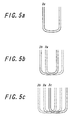
- FIG. 1 shows an embodiment in which the cord layers 3a, 3b and 3c are serially arranged with circumferentially shifted by the distance L, as shown in FIG. 3(a)
- the order in arranging the cord layer 3a, 3b and 3c is not particularly limited as far as the radial cord portions 15 can be evenly spaced after the carcass layer 4 is built.
- the cord layer 3c may be arranged between the cord layers 3a and 3b, as shown in FIG. 4, or the cord layer 3a may be arranged between the cord layers 3b and 3c as shown in FIG. 5.
- the pair of the split bead cores 13 and 14 constituting the bead 12 is preferably formed by helically winding bead wires 19 and 20, respectively.
- the bead wires 19 and 20 are helically winded to arrange them in piles substantially parallel to the circumferential cord portion 16, the overlap portion K is difficult to pass through the space between the pair of the split beads 13 and 14 so that the effect of restricting the carcass 4 by means of the bead is enhanced.
- the split bead core 14 especially locating outwardly in the tire's width direction is formed by aligning a plurality of arrays of bead wires 20 in the tire's width direction, the stiffness near the bead heal portion 18 is further enhanced to effectively prevent the pulling out of the carcass cord 2 and the coming off of the bead.
- the vertical distance D between the radially innermost end 21 of the split bead core 14 locating outwardly as viewed from the tire's width direction is preferably not more than 3 mm.
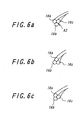
- the overlap portion K may be so formed that only the circumferential cord portion 16b substantially contacts with the other two cord portions 16a and 16c, as shown in FIG. 2, and more preferably the overlap portion K has a triple contact portion at which all of the circumferential cord portions 16a, 16b and 16c are substantially contacted with each other. That is, in the second overlap portion K2 shown in FIG. 1, if each of the circumferential cord portions 16a, 16b and 16c is placed at a vertex of a equilateral triangle, as shown in FIG. 6(c), positional relationships of the circumferential cord portions 16a, 16b and 16c are stabilized and mutual restriction forces therebetween are further increased by the contact. This makes the anchoring of the overlap portion K by means of the bead 12 stronger when a force is applied outwardly to the carcass 4 in the tire's radial direction.
- FIGS. 1-6 show embodiments in which the cord layer 3 consist of three layers, the cord layer 3 may consist of two layers in another embodiment. In that case, the overlap portion K has an arrangement shown in FIGS. 7 and 8.
- FIG. 6(a) shows an embodiment in which the circumferential cord portions 16a, 16b and 16c constituting the overlap portion K are placed at vertexes of an equilateral triangle and one of the vertexes is directed inwardly in the tire's radial direction.
- the circumferential cord portions 16a, 16b and 16c may be placed on the equilateral triangles shown in FIGS. 6(b) and 6(c) which are rotationally symmetry with the equilateral triangle shown in FIG. 6(a).
- the circumferential cord portions 16a, 16b and 16c may be placed at any vortexes of an equilateral triangle.
- the runflat tire having the above-mentioned configuration and according to the present invention has superior uniformity and can effectively inhibit both of pulling out of carcass cords and coming off of beads during running in the runflat state.
- the bead 12 consists of a pair of split bead cores 13 and 14 which locate on both sides of the carcass 4 to sandwich the carcass 4,
- the carcass 4 comprises at least one turn-up cord layers 22 folded around the split bead core14 located outside as viewed form the tire's width direction from the inner side to the outer side in the tire's width direction, and a folded end 23 of the turn-up cord layer 22 substantially consists of a plurality of the circumferential cord portions 24a, 24b and 24c.
- Such a tire has the bead 12 consisted of the split beads 13 and 14, so that, as mentioned in the above, the overlap portion is difficult to pass through the space between the split beads 13 and 14.
- the tire has the carcass 4 provided with the turn-up layer 22 which is formed in a turn-up configuration, so that the carcass cord 2 is further difficult to be pulled out even when a force is applied to the carcass 4 outwardly in the tire's radial direction and the radial cord portions 15 are pulled outwardly.
- the tire has the circumferential cord portions which circumferentially connect the respective inner ends of the adjacent radial cord portions, so that the bonding area between the carcass cord 2 and the rubber is increased and the carcass cord 2 is formed in a key-like shape (a configuration capable of hooking the rubber).
- a configuration makes the carcass cord 2 difficult to be pulled out, thereby exerting a remarkable effect especially in a state where a large force is applied, such as in a severe runflat running state.
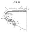
- the tire shown in FIG. 12 is another embodiment of the present invention which has a turn-up configuration.
- a stiffener rubber 25 tapered outwardly in the tire's radial direction is further arranged outside the bead 12 as viewed from the tire's radial direction.
- the carcass 4 comprises at least one turn-up cord layers 22 folded around the bead 12 and the stiffener rubber 25 from the inner side to the outer side in the tire's width direction.
- the folded end 23 of the turn-up cord layer 22 substantially consists of a plurality of the circumferential cord portions 24a- 24c (FIG. 11).
- Such a configuration may also exert the same effect as the above-mentioned turn-up configuration.
- FIG. 12 although shown is an embodiment in which the carcass 4 has a so-called up-and-down configuration consisting of one turn-up cord layer 8 and one downward cord layer, the carcass 4 may have various configurations.
- the folded end of the turn-up cord layer is laid in the tire's radial direction inside of a line segment PA which connects an arc center point P of said flange contour and an intersection A of the inner surface of the tire and a line extending outwardly in the tire's radial direction from the center point P at an angle of 60 degrees in relation to a line parallel to the rim radial line.
- the turn-up cord layer preferably has a so-called low turn-up configuration in which the height of the folded portion of the turn-up cord layer is smaller than the height of the rim flange.
- Such a configuration may avoid a large force caused by contacting with the rim especially in a normal running state. As a result, a separation can be effectively prevented at the folded ends of the carcass.
- the turn-up card layer having the low turn-up configuration is advantageous in the point where it may avoid a large force caused by contacting with the rim even in a runflat running state.
- the folded end of the turn-up cord layer is laid in the tire's radial direction outside of a line segment QB which connects an outermost point Q of the rim guard in the tire's width direction and an intersection B of the inner surface of the tire and a line extending outwardly in the tire's radial direction from the outermost point Q at an angle of 60 degrees in relation to a line parallel to the rim radial line.
- the sectional area S1 of the stiffener rubber 25 is preferably in a range between 20- 25% of the sectional area S2 of the reinforcing rubber 8, as shown as a hatched portion in FIG. 14. This is because the stiffness tends to be insufficient when the sectional area S1 of the stiffener rubber 25 is less than the sectional area S2 of the reinforcing rubber 8, while problems such as a heat generation, a weight increase and a deterioration in the riding quality may arise when the sectional area S1 is more than the sectional area S2.
- the circumferential cord portions 24a- 24c constituting the folded end 23 of the turn-up cord layer 22 are preferably arranged in such a manner that their positions in the tire's radial direction differ with each other, as shown in FIG. 11.
- the circumferential cord portions of the adjacent cord layers may be arranged without overlapping with each other, as shown in FIG. 15(b), since it can be effectively prevent the carcass cords from pulling out. If the carcass cord should be more strictly prevented from pulling out, an overlap portion at which the circumferential cord portions 24a- 24c in the different cord layers 3a- 3c substantially contact with each other is preferably formed at the position of each of the bead portions 5.
- a method may be mentioned by way of example, which comprising the steps of attaching, as needed, an inner liner, a reinforcing rubber, a carcass ply rubber and the like on a toroidal shaping core of a shaping body which has the shaping core, a bladder stored inside the periphery of the shaping core, and a detachable folding core enclosing the bladder when it is stored; forming, thereafter, a carcass by attaching a continuous cord while radially displacing it back and forth between the both bead portions at a given circumferential pitch P; and then folding ends of the carcass around the beads by removing the folding core and expanding the bladder stored therein.
- Pneumatic tires according to the present invention were experimentally manufactured and their performances in durability and bead-securing forces were evaluated. The details will be described below.
- Examples 1- 14 were runflat tires for passenger vehicles and their tire sizes were 215/65 R15.
- Each of Examples 1- 4 provided with a carcass, which did not have a tum-up cord layer but had overlap portions, and beads, which consist of split bead cores formed by helically winding a bead wire.
- Each of Examples 5- 13 provided with a carcass, which had a turn-up cord layer but did not have overlap portions, and beads, which consist of a single bead core formed by helically winding a bead wire.
- Example 15 provided with a carcass, which had a turn-up cord layer and overlap portions, and beads, which consist of a single bead core formed by helically winding a bead wire.
- Examples 1- 14 had parameters shown in Table 1 or 2.
- Table 1 "Distance between the bead inner end and the bead base” and “Distance between the circumferential cord portion and the bead base” are indicated as vertical distances the inner end of the bead or the circumferential cord portion in the tire's radial direction and the tire bead base or its extension.
- Table 2 "Sectional area of stiffener rubber” is indicated as a percentage of the sectional area of the stiffener rubber to the sectional area of the reinforcing rubber layer.
- the durability was evaluated in the following procedures.
- the above-mentioned test tires were equipped on standard rims specified by JATMA to form tire/wheel assemblies. Then, the bulb cores were removed to set their inner pressure at 0 kPa (relative pressure). These tires were pressed against a drum rotating at the surface velocity of 89 km/h with a loading force of 5.3 kN, and the distances until the tires were broken were measured. The durability was evaluated based on the measured distance. The evaluated results are shown in Tables 1 and 2.
- the bead-securing force was evaluated in the following procedures.
- the above-mentioned test tires were equipped on standard rims specified by JATMA to form tire/wheel assemblies.
- the bead portion was expanded at some segments and an expansion force was measured when the segment was expanded to the specific value defined for the standard rim.
- the bead-securing force was evaluated based on the measured force. The evaluated results are shown in Tables 1 and 2.
- each performance was represented by an index provided the performance of the Conventional Example is set to 100. The larger index means the better performance.
- Conventional Example Comparative Example Example 1 Example 2
- Type of bead Single Split Split Split Split Split Overlap portion No No Yes Yes Yes Yes Distance between the bead inner end and the bead base 5mm 5mm 5mm 5mm 3mm 3mm Distance between the circumferential cord portion and the bead base 2.5mm 2.5mm 2.5mm 2.5mm 2.5mm 2.5mm 2.5mm 0.5mm 0.5mm Durability 100 82 108 110 112 112 Bead-securing force 100 75 102 106 108 108
Landscapes
- Engineering & Computer Science (AREA)
- Mechanical Engineering (AREA)
- Tires In General (AREA)
- Tyre Moulding (AREA)
Abstract
The present invention is to provide a runflat tire which can effectively inhibit both of pulling out of carcass cords and coming off of beads during running in the runflat state. <??>A runflat tire according to the present invention comprises a carcass 4 toroidally extending over a pair of beads 5, a pair of sidewall portions 6 and a tread portion 7, and a reinforcing rubber layer 8 which has a crescent sectional shape and is arranged at the interior surface side of the carcass 4. The carcass 4 comprises at least one cord layers 3 including radial cord portions 15, which are radially-arrayed at a circumferential pitch P, and circumferential cord portions 16, which circumferentially connect respective inner ends of adjacent radial cord portion 15. <IMAGE>
Description
The present invention relates to a runflat tire capable of running for a
certain distance even in a state where the inner pressure thereof has inordinately
decreased or the tire has been punctured. In particular, the present invention is
intended to remarkably improve a uniformity of the tire as well as to effectively
inhibit both of pulling out of carcass cords and coming off of beads during
running in the runflat state.
As a so-called runflat tire which is capable of running for a certain
distance even when it gets an inordinate decrease in its inner pressure or it gets a
puncture, there are two types of tires, i.e. a so-called core type runflat tire and a
so-called side reinforced runflat tire. The former contains a supporting body in
a tire/rim assembly, and the latter has a reinforcing rubber layer which consists of
a relatively soft rubber and is arranged on the inner surface of the carcass at least
in the sidewall portion.
A dimensional deviation of the tire may greatly affect on its
uniformity especially for the side reinforced-type runflat tire, due to a material
stiffness of its reinforcing rubber layer. Therefore, when such a runflat tire is to
be built, it is necessary to satisfy a restrict standard in which a dimensional
accuracy of the carcass as well as a thickness and a shape of the reinforcing
rubber layer underneath the carcass are set higher than those of the ordinal tires.
A so-called core process (three dimensional process) is useful as a
method of building a tire satisfying such a restrict standard. In this process, a
green tire is formed in a shape similar to the product tire by attaching cords and
rubber on the outer surface of a rigid core, and then the green tire along with the
rigid core are vulcanized to yield the product tire without accompanying a large
radial expansion caused due to a shaping step or the like. The tire built by the
core process has a remarkably superior uniformity as compared with a tire built
by a conventional process which includes a shaping step.
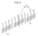
International Publication WO 00/73093, for example, discloses a tire
built by a core process. However, as shown in FIG. 9, since each of cord layers
102, 103 of a carcass 101 has such a configuration that a plurality of cords 104
are arranged between both bead portions at a given pitch, this tire has a problem
in which a force anchoring the carcass by means of the beads is insufficient and
thus the cords104 of such a carcass 101 are easily pulled out in the tire's radial
direction. Where the arrangement pitch between the carcass cords 104 is
narrowed and thereby increasing the carcass stiffness, it is useful that the
adjacent cord layers are so arranged that cords thereof are shifted with each other
at a given circumferential pitch. A tire having the configuration described in
the above-mentioned International Publication WO 00/73093 inevitably needs to
arrange a circumferential cord 105 extending in the circumferential direction
between the cord layers 102 and 103, which complicates the operation of
attaching the cords.
In JP 11-115420 A, which was filed by the present applicant and was
already laid-open, the present applicant disclosed a pneumatic tire that can
facilitate the operation of attaching carcass cords and can effectively inhibit the
carcass cords from pulling out by adopting a configuration in which split beads
sandwich a carcass layer formed by arranging two layers of cord assemblies on
the outer surface of the core while maintaining the overlap region and shifting
the cord assemblies with each other at a given distance L in the circumferential
direction.
In such a pneumatic tire, however, a distance between the radially
innermost end of the split bead and the tire bead base is not particularly defined.
When the distance becomes larger, the thickness of the rubber placed between
the inner end of the split bead in the tire's radial direction and the tire bead base
also becomes larger. Accordingly, such a pneumatic tire is not suitably applied
to a runflat tire since the lower part of the bead portion largely deforms and thus
the bead portion cannot exert a sufficient engagement force against the wheel rim
when the inner pressure of the tire decreases.
US Patent No. 3,815,652 describes a tire which has a carcass layer
built by using a continuous cord and arranging the cord while remaining the
overlap region and shifting in the circumferential direction. This tire, however,
cannot effectively prevent the carcass cords from pulling out, since a bead is
arranged on a single side of the carcass layer and the tire does not employ a
configuration in which the carcass layer is not sandwiched from the both sides.
US Patent No. 5,660,656 describes a tire which has such a configuration
that split beads sandwich a carcass layer built by using a continuous cord
and arranging the cord while shifting in the circumferential direction. This tire,
however, has a problem in which a overlapping portion of the cords constituting
the carcass layer present between the beads so that the tire cannot effectively
prevent the carcass cords from pulling out.
The object of the present invention is to provide a runflat tire which
can remarkably improve its uniformity as well as can effectively inhibit both of
pulling out of carcass cords and coming off of beads during running in the runflat
state by using a continuous cord and appropriately arranging the end portion of at
least one cord layers constituting the carcass.
To achieve the above-mentioned object, a runflat tire according to the
present invention comprises a carcass toroidally extending over a pair of bead
portions in which a bead core is embedded, a pair of sidewall portions and a tread
portion, and a reinforcing rubber layer which has a crescent sectional shape and
is arranged at the interior surface side of the carcass at least in the sidewall
portions, and is characterized in that the carcass comprises at least one cord
layers including a continuous cord and having a plurality of radial cord portions
radially-arrayed between the bead portions at a given circumferential pitch P and
a plurality of circumferential cord portions circumferentially connecting
respective inner ends of adjacent radial cord portions in the bead portion.
It is also preferred that the carcass comprises n (n is greater than or
equal to two) layers of the cord layers; the adjacent cord layers are so arranged
that their radial cord portions are circumferentially spaced with each other by a
distance L obtained when the circumferential pitch P is divided by the number n;
the circumferential cord portions of the different cord layers are substantially
contacted with each other to form an overlap portion in the bead portions; the
bead consists of a pair of split bead cores, the split bead cores locating on both
sides of the carcass to sandwich the carcass; the circumferential cord portions
locate below a lower end of the split bead cores as viewed from the tire's radial
direction; and an inner end in the tire's radial direction of the split bead core
locating outside as viewed from the tire's width direction is so placed that a
vertical distance from a tire bead base or its extension is not more than 5 mm,
particularly not more than 3mm.
It is further preferred that the split bead core constituting the bead is
formed by helically winding a bead wire.
It is further preferred that the number n of the cord layers constituting
the carcass is 3, and that the overlap portion has a triple contact portion at which
all of the circumferential cord portions of the different cord layers are
substantially contacted with each other.
If it is more necessary to prevent the carcass cords from pulling out, it
is preferred that the bead consist of a pair of split bead cores, the split bead cores
locating on both sides of the carcass to sandwich the carcass; and the carcass
comprises at least one turn-up cord layers folded around the split bead core
locating outside as viewed form the tire's width direction from the inner side to
the outer side in the tire's width direction; and wherein a folded end of the turn-up
cord layer substantially consists of a plurality of the circumferential cord
portions.
Meanwhile, if the bead consist not of a split bead but of an ordinal
bead, it is preferred that a stiffener rubber tapered outwardly in the tire's radial
direction is further arranged outside the bead in the tire's radial direction; the
carcass comprises at least one turn-up cord layers folded around the bead and the
stiffener rubber from the inner side to the outer side in the tire's width direction;
and wherein a folded end of the turn-up cord layer substantially consists of a
plurality of the circumferential cord portions.
It is further preferred that, as viewed in a section in the tire's width
direction under a condition where the tire is assembled to its standard rim to form
a tire/wheel assembly and then a small inner pressure of 15% of the maximum
inner pressure is applied to the tire with no load applied thereto, the folded end of
the turn-up cord layer is laid, in the tire's radial direction, inside of a line
segment PA which connects an arc center point P of the flange contour and an
intersection A of the inner surface of the tire and a line extending outwardly in
the tire's radial direction from the center point P at an angle of 60 degrees in
relation to a line parallel to the rim radial line.
It is also preferred, as viewed in a section in the tire's width direction
under a condition where the tire is assembled to its standard rim to form a
tire/wheel assembly and then a maximum load is applied to the tire with no inner
pressure applied thereto, the folded end of the turn-up cord layer is laid, in the
tire's radial direction, outside of a line segment QB which connects an outermost
point Q of the rim guard in the tire's width direction and an intersection B of the
inner surface of the tire and a line extending outwardly in the tire's radial
direction from the outermost point Q at an angle of 60 degrees in relation to a
line parallel to the rim radial line.
It is preferred, as viewed from the tire's width direction, the sectional
area of the stiffener rubber is in a range between 20- 25% of the sectional area of
the reinforcing rubber.
As used herein, the term "standard rim" refers to a standard rim
specified in an industrial specification, standard or the like such as JATMA, TRA
and ETRTO which are effective in the area where the tire is manufactured, sold
or used. The term "maximum pressure" refers to a maximum pressure (an inner
pressure corresponding to the maximum load capability) specified in the above-mentioned
industrial specification or standard.
It is also preferred that a plurality of the circumferential cord portions
constituting the folded end of the turn-up cord layer are so arranged that their
positions in the tire's radial direction differ with each other.
It is further preferred that an overlap portion at which the
circumferential cord portions in the different cord layers substantially contact
with each other is formed in the bead portions.
A method of building a tire including a carcass having the above-mentioned
turn-up cord layer, for example, comprises the steps of attaching, as
needed, an inner liner, a reinforcing rubber, a carcass ply rubber and the like on a
toroidal shaping core of a shaping body which has the shaping core, a bladder
stored inside the periphery of the shaping core, and a detachable folding core
enclosing the bladder when it is stored; forming, thereafter, a carcass by
attaching a continuous cord while radially displacing it back and forth between
the both bead portions at a given circumferential pitch P; and then folding ends
of the carcass around the beads by removing the folding core and expanding the
bladder stored therein.
Hereinafter, an embodiment of the present invention will be described
with reference to the drawings. FIG. 1 is a partially exploded perspective view
of a representative embodiment of a runflat tire according to the present invention
and FIG. 2 is a sectional view of the bead portion 5 of the runflat tire shown in
FIG. 1.
The runflat tire (hereinafter referred to as "tire") N shown in FIGS. 1
and 2 has a carcass 4 which is arranged outside a carcass liner 1 and which
consists of a layer 3 of a cord 2. The carcass 4 toroidally extends over a pair of
bead portions 5, a pair of sidewall portions 6 and a tread portion 7. A reinforcing
rubber layer 8 having a crescent sectional shape is provided on the inner surface
side of the sidewall portion 6 in relation to the carcass 4. On the periphery of
the crown portion of the carcass 4, there is provided a belt 10 built by laminating,
in the tire's radial direction, a plurality of cord layers in which a plurality of
cords 9 are aligned in parallel and are coated with rubber. A tread rubber layer
11 is arranged on the belt 10.
A constitutional feature of the present invention is to optimize the
carcass cords and the configuration of the bead, and more specifically the feature
is that the carcass comprises at least one cord layer including a continuous cord
and having a plurality of radial cord portions radially-arrayed between the bead
portions at a given circumferential pitch P and a plurality of circumferential cord
portions circumferentially connecting respective inner ends of adjacent radial
cord portions in the bead portion. As such a configuration is adopted to the tire
that a plurality of circumferential cord portions circumferentially connect the
respective inner ends of the adjacent radial cord portions in the bead portion, the
stiffness near the bead portion has been improved and thus the beads are
prevented from coming off especially during running in the runflat state.
In addition, as the ends of the carcass cords are connected by the circumferential
cord portions, which increases a force of anchoring the carcass by means of the
beads, the carcass cords are effectively prevented from pulling out even when a
force of pulling out the carcass cord is activated.
In a preferred embodiment of the present invention, the carcass 4
includes n (n is greater than or equal to two, and three in FIG. 3) layers of the
cord layers 3a, 3b and 3c which are composed of a continuous cord 2 and has a
plurality of radial cord portions 15 and circumferential portions 16 connecting
the respective inner ends of the adjacent radial cord portions 15 in the bead
portion 5. Sets of adjacent cord layers 3a and 3b, 3b and 3c are so arranged that
their radial cord portions 15 are circumferentially spaced with each other by a
distance L obtained when the circumferential pitch P is divided by the number n
(three in FIG. 1). The circumferential cord portions 16a, 16b and 16c of the
different cord layers 3a, 3b and 3c, respectively, are substantially contacted with
each other to form an overlap portion K in the bead portions 5. The bead 12
consists of a pair of split bead cores 13 and 14 which locate on both sides of the
carcass 4 to sandwich the carcass 4. The circumferential cord portions 16a, 16b
and 16c locate below the lower end of the split bead cores 13 and 14 as viewed
from the tire's radial direction. The inner end 21 in the tire's radial direction of
the split bead core 14 locating outside as viewed from the tire's width direction is
so placed that a vertical distance from a tire bead base 17 or its extension is not
more than 5 mm.
That is, when the three cord layers 3a, 3b and 3c are arranged to have
the circumferential distance L therebetween, the circumferential cord portions
16a, 16b and 16c of these cord layers 3a, 3b and 3c partly overlap and contact
with each other in the tire's width direction to form overlap portions K1, K2 and
K3 in the bead 5. In these overlap portions, the circumferential cord portions
16a, 16b and 16c contact and hold one another. Even when a force acts on the
radial cord portions 15 outwardly in the tire's radial direction and thus the
circumferential cord portion 16a continuing thereto is pulled outwardly, the
circumferential cord portion 16a is prevented from moving due to the adjacent
circumferential cord portion 16b, thereby inhibiting the carcass cord 2 from
pulling out. Further, the adjacent circumferential cord portions 16a, 16b and
16c contact and restrain with each other in the overlap portions K1, K2 and K3,
as shown in FIG. 2, so that they are integrated to give a diameter of the
circumscribed circle larger than that of a single carcass cord 2, while the pair of
split bead cores 13 and 14 are arranged to sandwich the carcass 4 at near the
border of the radial carcass cord portion 15 and the circumferential cord portion
16 so that the space therebetween is slightly larger than the diameter of the
carcass cord 2. The overlap portion K is difficult to pass through the space
between the pair of the split bead cores 13 and 14 since the circumferential cord
portions 16 are placed inside the inner ends 21 of the bead as viewed from the
tire's radial direction. Moreover, since the radial cord portion 15 and the
circumferential portion 16 are continuously formed, the circumferential cord
portion 16 continuing to the radial cord portion 15 is restrained by the bead 12
even when a force acts on the carcass 4 outwardly in the tire's radial direction
and the radial cord portion 15 is pulled out, resulting an effective prevention of
pulling down the carcass cords 2.
Further, the radial cord portion 15 and the circumferential cord
portion 16 connect with each other, so that a device for attaching a carcass cord,
for example, described in JP 2000-52448 A, which is also filed by the present
applicant, can be used to continuously form the carcass 4. This may improve
the uniformity and the productivity of the tire.
In addition, according to the conventional process, a smaller distance
between the radial cords yields a smaller feed of the tire's constitutional
members per an arrangement of the radial cord, resulting poor accuracy and
productivity, while a larger distance between the radial cords yields a smaller
strength of the carcass so that a cord with a larger diameter is needed to prevent
this. In contrast, according to the present invention, even if the distance L
between the radial cord portions 15 is small, the arrangement pitch P of the radial
cord portions 15 is large enough to be able to facilitate a manufacturing of the
carcass with closely arranged cords.
Moreover, as the vertical distance between the radially innermost end
of the split bead core 14 which locates outside as viewed from the tire's width
direction and the tire bead base 17 or its extension is set to 5 mm or less, the
stiffness near the bead heal portion 18 becomes higher. As a result, even when
the inner pressure decreases, the lower part of the bead portion 5 is less deformed
and thus the bead portion 5 exerts a sufficient engagement force against the rim of
the wheel (not shown) so that the bead is effectively prevented from coming off.
Although FIG. 1 shows an embodiment in which the cord layers 3a,
3b and 3c are serially arranged with circumferentially shifted by the distance L,
as shown in FIG. 3(a), the order in arranging the cord layer 3a, 3b and 3c is not
particularly limited as far as the radial cord portions 15 can be evenly spaced
after the carcass layer 4 is built. For example, the cord layer 3c may be arranged
between the cord layers 3a and 3b, as shown in FIG. 4, or the cord layer 3a may
be arranged between the cord layers 3b and 3c as shown in FIG. 5.
Furthermore, the pair of the split bead cores 13 and 14 constituting
the bead 12 is preferably formed by helically winding bead wires 19 and 20,
respectively. As the bead wires 19 and 20 are helically winded to arrange them
in piles substantially parallel to the circumferential cord portion 16, the overlap
portion K is difficult to pass through the space between the pair of the split beads
13 and 14 so that the effect of restricting the carcass 4 by means of the bead is
enhanced. In addition, as the split bead core 14 especially locating outwardly in
the tire's width direction is formed by aligning a plurality of arrays of bead wires
20 in the tire's width direction, the stiffness near the bead heal portion 18 is
further enhanced to effectively prevent the pulling out of the carcass cord 2 and
the coming off of the bead.
The vertical distance D between the radially innermost end 21 of the
split bead core 14 locating outwardly as viewed from the tire's width direction is
preferably not more than 3 mm. The closer the bead wire 20 is placed to the
bead heal portion 18, the larger the stiffness near the bead heal portion 18. This
reduces the deformation of the shape near the bead heal portion 18 and ensures a
sufficient engagement force of the bead portion 5 of the tire against the rim of the
wheel (not shown) even when the inner pressure decreases.
In this regard, the overlap portion K may be so formed that only the
circumferential cord portion 16b substantially contacts with the other two cord
portions 16a and 16c, as shown in FIG. 2, and more preferably the overlap
portion K has a triple contact portion at which all of the circumferential cord
portions 16a, 16b and 16c are substantially contacted with each other. That is,
in the second overlap portion K2 shown in FIG. 1, if each of the circumferential
cord portions 16a, 16b and 16c is placed at a vertex of a equilateral triangle, as
shown in FIG. 6(c), positional relationships of the circumferential cord portions
16a, 16b and 16c are stabilized and mutual restriction forces therebetween are
further increased by the contact. This makes the anchoring of the overlap
portion K by means of the bead 12 stronger when a force is applied outwardly to
the carcass 4 in the tire's radial direction.
Although FIGS. 1-6 show embodiments in which the cord layer 3
consist of three layers, the cord layer 3 may consist of two layers in another
embodiment. In that case, the overlap portion K has an arrangement shown in
FIGS. 7 and 8.
FIG. 6(a) shows an embodiment in which the circumferential cord
portions 16a, 16b and 16c constituting the overlap portion K are placed at
vertexes of an equilateral triangle and one of the vertexes is directed inwardly in
the tire's radial direction. The circumferential cord portions 16a, 16b and 16c,
however, may be placed on the equilateral triangles shown in FIGS. 6(b) and 6(c)
which are rotationally symmetry with the equilateral triangle shown in FIG. 6(a).
The circumferential cord portions 16a, 16b and 16c may be placed at any
vortexes of an equilateral triangle.
The runflat tire having the above-mentioned configuration and
according to the present invention has superior uniformity and can effectively
inhibit both of pulling out of carcass cords and coming off of beads during
running in the runflat state.
However, under a more severe condition where the tire is used in the
runflat state with a higher load being applied, it may be necessary to further
inhibit both of pulling out of carcass cords and coming off of beads during
running in the runflat state.
In this case, it is preferred that the bead 12 consists of a pair of split
bead cores 13 and 14 which locate on both sides of the carcass 4 to sandwich the
carcass 4, the carcass 4 comprises at least one turn-up cord layers 22 folded
around the split bead core14 located outside as viewed form the tire's width
direction from the inner side to the outer side in the tire's width direction, and a
folded end 23 of the turn-up cord layer 22 substantially consists of a plurality of
the circumferential cord portions 24a, 24b and 24c.
Such a tire has the bead 12 consisted of the split beads 13 and 14, so
that, as mentioned in the above, the overlap portion is difficult to pass through
the space between the split beads 13 and 14. In addition, the tire has the carcass
4 provided with the turn-up layer 22 which is formed in a turn-up configuration,
so that the carcass cord 2 is further difficult to be pulled out even when a force is
applied to the carcass 4 outwardly in the tire's radial direction and the radial cord
portions 15 are pulled outwardly. Moreover, the tire has the circumferential
cord portions which circumferentially connect the respective inner ends of the
adjacent radial cord portions, so that the bonding area between the carcass cord 2
and the rubber is increased and the carcass cord 2 is formed in a key-like shape (a
configuration capable of hooking the rubber). Such a configuration makes the
carcass cord 2 difficult to be pulled out, thereby exerting a remarkable effect
especially in a state where a large force is applied, such as in a severe runflat
running state.
The tire shown in FIG. 12 is another embodiment of the present
invention which has a turn-up configuration. In this tire, a stiffener rubber 25
tapered outwardly in the tire's radial direction is further arranged outside the
bead 12 as viewed from the tire's radial direction. The carcass 4 comprises at
least one turn-up cord layers 22 folded around the bead 12 and the stiffener
rubber 25 from the inner side to the outer side in the tire's width direction.
The folded end 23 of the turn-up cord layer 22 substantially consists of a plurality
of the circumferential cord portions 24a- 24c (FIG. 11). Such a configuration
may also exert the same effect as the above-mentioned turn-up configuration.
In FIG. 12, although shown is an embodiment in which the carcass 4 has a so-called
up-and-down configuration consisting of one turn-up cord layer 8 and one
downward cord layer, the carcass 4 may have various configurations.
It is preferred that, as viewed in a section in the tire's width direction
under a condition where the tire is assembled to its standard rim to form a tire
wheel and then a small air pressure of 15% of the maximum inner pressure is
applied to the tire (so-called a free-standing state) with no load applied thereto
(FIG. 12), the folded end of the turn-up cord layer is laid in the tire's radial
direction inside of a line segment PA which connects an arc center point P of said
flange contour and an intersection A of the inner surface of the tire and a line
extending outwardly in the tire's radial direction from the center point P at an
angle of 60 degrees in relation to a line parallel to the rim radial line. In other
words, the turn-up cord layer preferably has a so-called low turn-up configuration
in which the height of the folded portion of the turn-up cord layer is smaller than
the height of the rim flange. Such a configuration may avoid a large force
caused by contacting with the rim especially in a normal running state. As a
result, a separation can be effectively prevented at the folded ends of the carcass.
In addition, the turn-up card layer having the low turn-up configuration is
advantageous in the point where it may avoid a large force caused by contacting
with the rim even in a runflat running state.
In order to effectively prevent a separation at the folded ends of the
carcass in a runflat running state, it is also preferred that, as viewed in a section
in the tire's width direction under a condition where the tire is assembled to its
standard rim to form a tire wheel and then a maximum load is applied to the tire
with no air pressure applied thereto, the folded end of the turn-up cord layer is
laid in the tire's radial direction outside of a line segment QB which connects an
outermost point Q of the rim guard in the tire's width direction and an intersection
B of the inner surface of the tire and a line extending outwardly in the tire's
radial direction from the outermost point Q at an angle of 60 degrees in relation
to a line parallel to the rim radial line.
If the tire necessarily has a stable and sufficient runflat performance,
as viewed from the tire's width direction, the sectional area S1 of the stiffener
rubber 25 is preferably in a range between 20- 25% of the sectional area S2 of
the reinforcing rubber 8, as shown as a hatched portion in FIG. 14. This is
because the stiffness tends to be insufficient when the sectional area S1 of the
stiffener rubber 25 is less than the sectional area S2 of the reinforcing rubber 8,
while problems such as a heat generation, a weight increase and a deterioration in
the riding quality may arise when the sectional area S1 is more than the sectional
area S2.
Furthermore, in order to disperse the stress acting on the folded ends
and to effectively prevent an occurrence and growth of a separation, the circumferential
cord portions 24a- 24c constituting the folded end 23 of the turn-up cord
layer 22 are preferably arranged in such a manner that their positions in the tire's
radial direction differ with each other, as shown in FIG. 11.
In the turn-up cord layer 22 constituting the carcass, the circumferential
cord portions of the adjacent cord layers may be arranged without overlapping
with each other, as shown in FIG. 15(b), since it can be effectively prevent the
carcass cords from pulling out. If the carcass cord should be more strictly
prevented from pulling out, an overlap portion at which the circumferential cord
portions 24a- 24c in the different cord layers 3a- 3c substantially contact with
each other is preferably formed at the position of each of the bead portions 5.
As an example of a method of building the above-mentioned runflat
tire having the carcass consisted of the turn-up cord layer, a method may be
mentioned by way of example, which comprising the steps of attaching, as
needed, an inner liner, a reinforcing rubber, a carcass ply rubber and the like on a
toroidal shaping core of a shaping body which has the shaping core, a bladder
stored inside the periphery of the shaping core, and a detachable folding core
enclosing the bladder when it is stored; forming, thereafter, a carcass by
attaching a continuous cord while radially displacing it back and forth between
the both bead portions at a given circumferential pitch P; and then folding ends
of the carcass around the beads by removing the folding core and expanding the
bladder stored therein.
Although illustrative embodiments of the present invention have been
described above, variations and modifications may be made without departing
from the scope of the invention as defined by the appended claims.
Pneumatic tires according to the present invention were experimentally
manufactured and their performances in durability and bead-securing forces
were evaluated. The details will be described below.
Examples 1- 14 were runflat tires for passenger vehicles and their tire
sizes were 215/65 R15. Each of Examples 1- 4 provided with a carcass, which
did not have a tum-up cord layer but had overlap portions, and beads, which
consist of split bead cores formed by helically winding a bead wire. Each of
Examples 5- 13 provided with a carcass, which had a turn-up cord layer but did
not have overlap portions, and beads, which consist of a single bead core formed
by helically winding a bead wire. Example 15 provided with a carcass, which
had a turn-up cord layer and overlap portions, and beads, which consist of a
single bead core formed by helically winding a bead wire. Examples 1- 14 had
parameters shown in Table 1 or 2. In Table 1, "Distance between the bead inner
end and the bead base" and "Distance between the circumferential cord portion
and the bead base" are indicated as vertical distances the inner end of the bead or
the circumferential cord portion in the tire's radial direction and the tire bead
base or its extension. In Table 2, "Sectional area of stiffener rubber" is
indicated as a percentage of the sectional area of the stiffener rubber to the
sectional area of the reinforcing rubber layer. In Table 2, "Position of the
folded end" means the position of the folded portion of the turn-up cord layer of
the carcass, "BQ- PA" means that the folded portion locates between the line
segments BQ and PA, and ">QB" means that the folded portion locates inside the
line segment QB in the tire's radial direction.
For the purpose of comparison, a tire having the conventional carcass
configuration (Conventional Example) and a tire having the carcass configuration
shown in FIGS. 15a and 15b (Comparative Example), both of which had the same
tire size as those of Examples 1- 14, were also experimentally manufactured.
The durability was evaluated in the following procedures. The above-mentioned
test tires were equipped on standard rims specified by JATMA to form
tire/wheel assemblies. Then, the bulb cores were removed to set their inner
pressure at 0 kPa (relative pressure). These tires were pressed against a drum
rotating at the surface velocity of 89 km/h with a loading force of 5.3 kN, and the
distances until the tires were broken were measured. The durability was
evaluated based on the measured distance. The evaluated results are shown in
Tables 1 and 2.
The bead-securing force was evaluated in the following procedures.
The above-mentioned test tires were equipped on standard rims specified by
JATMA to form tire/wheel assemblies. Then, by means of a device for
measuring the bead-securing force which is commercially available from
Hofmann, the bead portion was expanded at some segments and an expansion
force was measured when the segment was expanded to the specific value
defined for the standard rim. The bead-securing force was evaluated based on
the measured force. The evaluated results are shown in Tables 1 and 2.
In Tables 1 and 2, each performance was represented by an index
provided the performance of the Conventional Example is set to 100. The larger
index means the better performance.

| Conventional Example | Comparative Example | Example 1 | Example 2 | Example 3 | Example 4 | |
| Pitch P | 1.5 | 1.5 | 3 | 4.5 | 6 | 4.5 |
| Number of | 1 | 1 | 3 | 3 | 4 | 3 |
| L=P/n | 1.5 | 1.5 | 1.5 | 1.5 | 1.5 | 1.5 |
| Type of bead | Single | Split | Split | Split | Split | Split |
| Overlap portion | No | No | Yes | Yes | Yes | Yes |
| Distance between the bead inner end and the bead base | 5mm | 5mm | 5mm | 5mm | 3mm | 3mm |
| Distance between the circumferential cord portion and the bead base | 2.5mm | 2.5mm | 2.5mm | 2.5mm | 0.5mm | 0.5mm |
| Durability | 100 | 82 | 108 | 110 | 112 | 112 |
| Bead-securing force | 100 | 75 | 102 | 106 | 108 | 108 |
As seen from the results of Tables 1 and 2, it is clear that each of
Examples 1- 14 has superior durability and bead-securing force as compared with
Conventional Example and Comparative Example.
According to the present invention, it is possible to provide a runflat
tire which can effectively inhibit both of pulling out of carcass cords and coming
off of beads during running in the runflat state.
Claims (14)
- A runflat tire comprising a carcass toroidally extending over a pair of bead portions in which beads are embedded, a pair of sidewall portions and a tread portion, and a reinforcing rubber layer which has a crescent sectional shape and is arranged at the interior surface side of the carcass at least in the sidewall portions, characterized in that
said carcass comprises at least one cord layers including a continuous cord and having a plurality of radial cord portions radially-arrayed between the bead portions at a given circumferential pitch P and a plurality of circumferential cord portions circumferentially connecting respective inner ends of adjacent radial cord portions in the bead portion. - The runflat tire according to Claim 1, wherein said carcass comprises n (n is greater than or equal to two) layers of the cord layers;
the adjacent cord layers are so arranged that their radial cord portions are circumferentially spaced with each other by a distance L obtained when said circumferential pitch P is divided by the number n;
the circumferential cord portions of the different cord layers are substantially contacted with each other to form an overlap portion in the bead portions;
said bead consists of a pair of split bead cores, said split bead cores locating on both sides of the carcass to sandwich the carcass;
said circumferential cord portions locate below a lower end of the split bead cores as viewed from the tire's radial direction; and
an inner end in the tire's radial direction of the split bead core located outside as viewed from the tire's width direction is so placed that a vertical distance from a tire bead base or its extension is not more than 5 mm. - The runflat tire according to Claim 2, wherein said split bead core constituting the bead is formed by helically winding a bead wire.
- The runflat tire according to Claim 2 or 3, wherein said vertical distance is not more than 3 mm.
- The runflat tire according to Claim 2, 3 or 4, wherein said number n of the cord layers constituting the carcass is 3.
- The runflat tire according to Claim 5, wherein said overlap portion has a triple contact portion at which all of the circumferential cord portions of the different cord layers are substantially contacted with each other.
- The runflat tire according to Claim 1, wherein said bead consists of a pair of split bead cores, said split bead cores locating on both sides of the carcass to sandwich the carcass; and
said carcass comprises at least one turn-up cord layers folded around the split bead core locating outside in the tire's width direction from the inner side to the outer side in the tire's width direction; and wherein
a folded end of said turn-up cord layer substantially consists of a plurality of the circumferential cord portions. - The runflat tire according to Claim 1, wherein a stiffener rubber tapered outwardly in the tire's radial direction is further arranged outside the bead in the tire's radial direction;
said carcass comprises at least one turn-up cord layers folded around the bead and the stiffener rubber from the inner side to the outer side in the tire's width direction; and wherein
a folded end of said turn-up cord layer substantially consists of a plurality of the circumferential cord portions. - The runflat tire according to Claim 7 or 8, wherein, as viewed in a section in the tire's width direction under a condition where the tire is assembled to its standard rim to form a tire/wheel assembly and then a small inner pressure of 15% of the maximum inner pressure is applied to the tire with no load applied thereto, the folded end of the turn-up cord layer is laid, in the tire's radial direction, inside of a line segment PA which connects an arc center point P of said flange contour and an intersection A of the inner surface of the tire and a line extending outwardly in the tire's radial direction from the center point P at an angle of 60 degrees in relation to a line parallel to the rim radial line.
- The runflat tire according to Claim 7, 8 or 9, wherein, as viewed in a section in the tire's width direction under a condition where the tire is assembled to its standard rim to form a tire/wheel assembly and then a maximum load is applied to the tire with no inner pressure applied thereto, the folded end of the turn-up cord layer is laid, in the tire's radial direction, outside of a line segment QB which connects an outermost point Q of said rim guard in the tire's width direction and an intersection B of the inner surface of the tire and a line extending outwardly in the tire's radial direction from the outermost point Q at an angle of 60 degrees in relation to a line parallel to the rim radial line.
- The runflat tire according to any one of Claims 7- 10, wherein, as viewed from the tire's width direction, the sectional area of said stiffener rubber is in a range between 20- 25% of the sectional area of said reinforcing rubber.
- The runflat tire according to any one of Claims 7- 11, wherein a plurality of said circumferential cord portions constituting said folded end of the turn-up cord layer are so arranged that their positions in the tire's radial direction differ with each other.
- The runflat tire according to any one of Claims 7- 12, wherein an overlap portion at which the circumferential cord portions in the different cord layers substantially contact with each other is formed in the bead portion.
- A method of building the tire according any one of Claims 7- 13, comprising the steps of
attaching, as needed, an inner liner, a reinforcing rubber, a carcass ply rubber and the like on a toroidal shaping core of a shaping body which has the shaping core, a bladder stored inside the periphery of the shaping core, and a detachable folding core enclosing the bladder when it is stored; forming, thereafter, a carcass by attaching a continuous cord while radially displacing it back and forth between the both bead portions at a given circumferential pitch P; and then folding ends of the carcass around the beads by removing the folding core and expanding the bladder stored therein.
Applications Claiming Priority (3)
| Application Number | Priority Date | Filing Date | Title |
|---|---|---|---|
| JP2002117037 | 2002-04-19 | ||
| JP2002117037 | 2002-04-19 | ||
| PCT/JP2003/005056 WO2003089258A1 (en) | 2002-04-19 | 2003-04-21 | Run flat tire and method of manufacturing the tire |
Publications (2)
| Publication Number | Publication Date |
|---|---|
| EP1502772A1 true EP1502772A1 (en) | 2005-02-02 |
| EP1502772A4 EP1502772A4 (en) | 2010-11-24 |
Family
ID=29243479
Family Applications (1)
| Application Number | Title | Priority Date | Filing Date |
|---|---|---|---|
| EP03717666A Withdrawn EP1502772A4 (en) | 2002-04-19 | 2003-04-21 | Run flat tire and method of manufacturing the tire |
Country Status (5)
| Country | Link |
|---|---|
| US (1) | US20060011282A1 (en) |
| EP (1) | EP1502772A4 (en) |
| JP (1) | JP4279150B2 (en) |
| CN (1) | CN100427301C (en) |
| WO (1) | WO2003089258A1 (en) |
Cited By (1)
| Publication number | Priority date | Publication date | Assignee | Title |
|---|---|---|---|---|
| EP4212358A1 (en) | 2022-01-14 | 2023-07-19 | Continental Reifen Deutschland GmbH | Pneumatic tyre for vehicles |
Families Citing this family (10)
| Publication number | Priority date | Publication date | Assignee | Title |
|---|---|---|---|---|
| US20040154727A1 (en) * | 2003-02-11 | 2004-08-12 | Weissert James Thomas | Method and apparatus for manufacturing carcass plies for a tire |
| JP4593478B2 (en) * | 2004-01-13 | 2010-12-08 | 株式会社ブリヂストン | Tire manufacturing method |
| JP2006131001A (en) * | 2004-11-04 | 2006-05-25 | Bridgestone Corp | Pneumatic tire and its manufacturing method |
| JP5171078B2 (en) * | 2007-03-16 | 2013-03-27 | 株式会社ブリヂストン | Pneumatic tire |
| KR101059102B1 (en) * | 2009-03-30 | 2011-08-25 | 한국타이어 주식회사 | Car tires with improved carcass turnover edges |
| KR101154324B1 (en) * | 2009-12-04 | 2012-06-13 | 한국타이어 주식회사 | Vehicle tire improved bead member |
| JP5066220B2 (en) * | 2010-05-17 | 2012-11-07 | 住友ゴム工業株式会社 | Pneumatic tire and manufacturing method thereof |
| KR101800170B1 (en) * | 2012-06-21 | 2017-11-22 | 미쉐린 러쉐르슈 에 떼크니크 에스.에이. | Method for adhering an innerliner to a carcass ply of a tire |
| NL2014555B1 (en) * | 2014-10-13 | 2016-10-04 | Vmi Holland Bv | Method and drum for manufacturing a tyre, in particular a run-flat tyre. |
| CN107053956B (en) * | 2017-04-17 | 2019-09-13 | 尹博功 | Steel tire and its manufacturing process |
Family Cites Families (15)
| Publication number | Priority date | Publication date | Assignee | Title |
|---|---|---|---|---|
| DE3121281A1 (en) * | 1981-05-29 | 1983-01-20 | Wolf-Dietrich 6718 Grünstadt Schöllhorn | "UREA FORMALDHYD RESIN, ITS PRODUCTION AND USE" |
| US5660656A (en) * | 1992-08-05 | 1997-08-26 | Sedepro | Tire with anchored carcass |
| GB9400657D0 (en) * | 1994-01-14 | 1994-03-09 | Boc Group Plc | Treatment of gas mixtures |
| JP3113564B2 (en) * | 1995-12-08 | 2000-12-04 | 住友ゴム工業株式会社 | Pneumatic tire |
| US5885387A (en) * | 1995-12-08 | 1999-03-23 | Sumitomo Rubber Industries, Ltd. | Pneumatic tire having endless carcass cord ply |
| JPH10305711A (en) * | 1997-05-06 | 1998-11-17 | Yokohama Rubber Co Ltd:The | Pneumatic radial tire |
| US6026878A (en) * | 1997-05-29 | 2000-02-22 | The Goodyear Tire & Rubber Company | Inextensible high temperature resistant tire |
| JP4131587B2 (en) * | 1997-08-15 | 2008-08-13 | 株式会社ブリヂストン | Pneumatic tire and method for forming the same |
| JP3358985B2 (en) * | 1998-01-07 | 2002-12-24 | 住友ゴム工業株式会社 | Radial tires for heavy loads |
| JP4233658B2 (en) * | 1998-06-01 | 2009-03-04 | 株式会社ブリヂストン | Carcass cord attaching apparatus and tire manufacturing method |
| JP4382177B2 (en) * | 1998-09-01 | 2009-12-09 | 株式会社ブリヂストン | Pneumatic radial tire |
| EP1100688A1 (en) * | 1999-05-27 | 2001-05-23 | Michelin Recherche Et Technique S.A. | Runflat tire having optimized carcass path |
| DE60112520T2 (en) * | 2000-03-31 | 2006-06-08 | Pirelli Pneumatici S.P.A. | SELF-WEARING VEHICLE AIR TIRE AND METHOD FOR THE PRODUCTION THEREOF |
| CN1599675A (en) * | 2000-10-10 | 2005-03-23 | 米其林技术公司 | Tire having more carcass layers in sidewall than in bead |
| US20050081974A1 (en) * | 2001-10-08 | 2005-04-21 | Michelin Recherche Et Technique S.A. | Tire having more carcass layers in sidewall than in bead |
-
2003
- 2003-04-21 WO PCT/JP2003/005056 patent/WO2003089258A1/en not_active Ceased
- 2003-04-21 CN CNB038114240A patent/CN100427301C/en not_active Expired - Fee Related
- 2003-04-21 JP JP2003585989A patent/JP4279150B2/en not_active Expired - Fee Related
- 2003-04-21 US US10/511,137 patent/US20060011282A1/en not_active Abandoned
- 2003-04-21 EP EP03717666A patent/EP1502772A4/en not_active Withdrawn
Cited By (1)
| Publication number | Priority date | Publication date | Assignee | Title |
|---|---|---|---|---|
| EP4212358A1 (en) | 2022-01-14 | 2023-07-19 | Continental Reifen Deutschland GmbH | Pneumatic tyre for vehicles |
Also Published As
| Publication number | Publication date |
|---|---|
| WO2003089258A1 (en) | 2003-10-30 |
| JP4279150B2 (en) | 2009-06-17 |
| CN100427301C (en) | 2008-10-22 |
| EP1502772A4 (en) | 2010-11-24 |
| CN1655957A (en) | 2005-08-17 |
| US20060011282A1 (en) | 2006-01-19 |
| JPWO2003089258A1 (en) | 2005-08-25 |
Similar Documents
| Publication | Publication Date | Title |
|---|---|---|
| US7316255B2 (en) | Pneumatic tire and method of manufacturing the same | |
| EP2308694B1 (en) | Pneumatic tire | |
| JP2724291B2 (en) | Heavy duty tire | |
| US11312190B2 (en) | Pneumatic tire | |
| US20060011282A1 (en) | Run flat tire and method of manufacturing the tire | |
| US9440406B2 (en) | Pneumatic tire and method of forming circumferential belt layer of the same | |
| CN100572107C (en) | Tire and manufacture method with improved high speed performance | |
| US7096908B2 (en) | Self-supporting tyre for a vehicle wheel, and method of making the tyre | |
| JP2020152044A (en) | Motorcycle tire manufacturing method and profile deck | |
| JP2002513360A (en) | Tire with inverted carcass ply folded configuration | |
| CN103889699B (en) | For the manufacture of airtyred method | |
| JP2004268820A (en) | Pneumatic tire | |
| JP2009001108A (en) | Pneumatic radial tire | |
| JP2002019430A (en) | Pneumatic tire | |
| JP2009090974A (en) | Pneumatic tire | |
| JP2002507515A (en) | Rock bead structure | |
| JP2000016032A (en) | Pneumatic radial tire | |
| JP2003094913A (en) | Winter run flat tire and manufacturing method thereof | |
| EP3711979A1 (en) | Motorcycle tire | |
| EP1433590A2 (en) | Tire with composite ply structure and method of manufacture | |
| JP2004306680A (en) | Pneumatic radial tire and its manufacturing method | |
| EP0317318B1 (en) | Method of manufacturing pneumatic tire | |
| JP2013067256A (en) | Pneumatic tire | |
| US10744826B2 (en) | Pneumatic tire | |
| JP7590161B2 (en) | Pneumatic tires |
Legal Events
| Date | Code | Title | Description |
|---|---|---|---|
| PUAI | Public reference made under article 153(3) epc to a published international application that has entered the european phase |
Free format text: ORIGINAL CODE: 0009012 |
|
| 17P | Request for examination filed |
Effective date: 20041109 |
|
| AK | Designated contracting states |
Kind code of ref document: A1 Designated state(s): AT BE BG CH CY CZ DE DK EE ES FI FR GB GR HU IE IT LI LU MC NL PT RO SE SI SK TR |
|
| A4 | Supplementary search report drawn up and despatched |
Effective date: 20101021 |
|
| 17Q | First examination report despatched |
Effective date: 20110214 |
|
| STAA | Information on the status of an ep patent application or granted ep patent |
Free format text: STATUS: THE APPLICATION IS DEEMED TO BE WITHDRAWN |
|
| 18D | Application deemed to be withdrawn |
Effective date: 20130430 |