EP1502693A1 - Welding device and method - Google Patents
Welding device and method Download PDFInfo
- Publication number
- EP1502693A1 EP1502693A1 EP04012102A EP04012102A EP1502693A1 EP 1502693 A1 EP1502693 A1 EP 1502693A1 EP 04012102 A EP04012102 A EP 04012102A EP 04012102 A EP04012102 A EP 04012102A EP 1502693 A1 EP1502693 A1 EP 1502693A1
- Authority
- EP
- European Patent Office
- Prior art keywords
- welding
- pipes
- welded
- electrode
- welding device
- Prior art date
- Legal status (The legal status is an assumption and is not a legal conclusion. Google has not performed a legal analysis and makes no representation as to the accuracy of the status listed.)
- Withdrawn
Links
Images


Classifications
-
- B—PERFORMING OPERATIONS; TRANSPORTING
- B23—MACHINE TOOLS; METAL-WORKING NOT OTHERWISE PROVIDED FOR
- B23K—SOLDERING OR UNSOLDERING; WELDING; CLADDING OR PLATING BY SOLDERING OR WELDING; CUTTING BY APPLYING HEAT LOCALLY, e.g. FLAME CUTTING; WORKING BY LASER BEAM
- B23K9/00—Arc welding or cutting
- B23K9/12—Automatic feeding or moving of electrodes or work for spot or seam welding or cutting
- B23K9/127—Means for tracking lines during arc welding or cutting
- B23K9/1272—Geometry oriented, e.g. beam optical trading
- B23K9/1274—Using non-contact, optical means, e.g. laser means
-
- B—PERFORMING OPERATIONS; TRANSPORTING
- B23—MACHINE TOOLS; METAL-WORKING NOT OTHERWISE PROVIDED FOR
- B23K—SOLDERING OR UNSOLDERING; WELDING; CLADDING OR PLATING BY SOLDERING OR WELDING; CUTTING BY APPLYING HEAT LOCALLY, e.g. FLAME CUTTING; WORKING BY LASER BEAM
- B23K37/00—Auxiliary devices or processes, not specially adapted for a procedure covered by only one of the other main groups of this subclass
- B23K37/04—Auxiliary devices or processes, not specially adapted for a procedure covered by only one of the other main groups of this subclass for holding or positioning work
- B23K37/053—Auxiliary devices or processes, not specially adapted for a procedure covered by only one of the other main groups of this subclass for holding or positioning work aligning cylindrical work; Clamping devices therefor
- B23K37/0533—External pipe alignment clamps
-
- B—PERFORMING OPERATIONS; TRANSPORTING
- B23—MACHINE TOOLS; METAL-WORKING NOT OTHERWISE PROVIDED FOR
- B23K—SOLDERING OR UNSOLDERING; WELDING; CLADDING OR PLATING BY SOLDERING OR WELDING; CUTTING BY APPLYING HEAT LOCALLY, e.g. FLAME CUTTING; WORKING BY LASER BEAM
- B23K26/00—Working by laser beam, e.g. welding, cutting or boring
- B23K26/70—Auxiliary operations or equipment
- B23K26/702—Auxiliary equipment
-
- B—PERFORMING OPERATIONS; TRANSPORTING
- B23—MACHINE TOOLS; METAL-WORKING NOT OTHERWISE PROVIDED FOR
- B23K—SOLDERING OR UNSOLDERING; WELDING; CLADDING OR PLATING BY SOLDERING OR WELDING; CUTTING BY APPLYING HEAT LOCALLY, e.g. FLAME CUTTING; WORKING BY LASER BEAM
- B23K2101/00—Articles made by soldering, welding or cutting
- B23K2101/04—Tubular or hollow articles
- B23K2101/06—Tubes
-
- B—PERFORMING OPERATIONS; TRANSPORTING
- B23—MACHINE TOOLS; METAL-WORKING NOT OTHERWISE PROVIDED FOR
- B23K—SOLDERING OR UNSOLDERING; WELDING; CLADDING OR PLATING BY SOLDERING OR WELDING; CUTTING BY APPLYING HEAT LOCALLY, e.g. FLAME CUTTING; WORKING BY LASER BEAM
- B23K2101/00—Articles made by soldering, welding or cutting
- B23K2101/04—Tubular or hollow articles
- B23K2101/10—Pipe-lines
Definitions
- This invention relates a welding device for butt welding pipes and a method thereof.
- a common method is that pipe units linked by welding a plurality of pipes are made at a clean booth where the clearance can be controlled, and then the pipe units are welded according to a place to be laid.
- a Japanese Laid Open Publication 2000-334564 discloses a method for wilding pipes.
- a groove sensor having an emitting unit and a receiving unit for a laser beam, is used to irradiate the laser beam to grooves formed at the end of a pipe.
- a groove shape is detected according to the laser beam that projects the groove and reaches the receiving section.
- a welding torch is arranged according to the position of the detected groove so as to weld the pipe.
- FIGs. 3 to 5 show an exemplary welding device used to weld a pipe.
- the welding device comprises a head unit 1, an electrode unit 2, a fixing clamp 3 for holding pipes 4, 5 to be welded and a cover plate 9 formed on the fixing clamp 3.
- the head unit 1 comprises a base 11, a first and a second extension portions 12, 12 respectively extending upwards from the two ends of the base 11.
- the electrode unit 2 comprises an arc-shaped rotation member 21 and a welding electrode 22 formed on the rotation member 21.
- the fixing clamp 3 comprises a first clamp 31 and a second clamp 32.
- the first clamp 31 is used to hold one pipe 4 to be welded, and comprises a first and a second holders 33, 34 for sandwiching the pipe 4 both top and bottom.
- the second clamp 32 is used to hold the other pipe 5 to be welded, and comprises a first and a second holders 37, 38 for sandwiching the pipe 5 both top and bottom.
- the first holders 33, 37 are respectively formed in a plate shape having a pipe-holding recessions 33a, 37a that are conformed to outer circumferences of the pipes 4, 5.
- the second holders 34, 38 are respectively formed in a plate shape having a pipe-holding recessions 34a, 38a that are conformed to outer circumferences of the pipes 4, 5.
- the cover plate 9 comprises a cover body 92 and a transparent protection plate 93.
- the cover body 92 includes a position-identification window 91 for identifying positions of butt edge surfaces 4a, 5a of the pipes 4, 5 to be welded, and the transparent protection plate 93 is used to cover the window 91.
- the welding device can place the butt edge surfaces 4a, 5a of the pipes 4, 5 to be welded in a substantially sealed space S encompassed by the head unit 1, the fixing clamp 3 and the cover plate 9.
- a position indicator (a marking line) 51 is formed by using a pen, etc. at a position apart from the butt edge surface 4a of the pipe 4 to be welded by the distance a1. Also, another position indicator (a marking line) 51 is formed at a position apart from the butt edge surface 5a of the pipe 5 to be welded by the distance a2.
- the positions of the position indicators 51 are respectively set to the outer-rim surface of the first and the second clamps 31, 32, and the pipes 4, 5 is arranged between the extension portions 12, 13 of the head unit 1 and then held by the clamps 31, 32. In this way, the pipes 4, 5 to be welded are positioned in a manner that the butt edge surfaces 4a, 5a are butted to each other.
- positions (positions in the axial direction of the pipes 4, 5, and refer to an axial position, hereinafter) of the butt edge surfaces 4a, 5a of the pipes 4,5 to be welded and the welding electrode 22 are consistent.
- the positioning of the pipes 4, 5 to be welded in the axial direction is performed by matching the position of the position indicators 51 with the clamps 31, 32.
- an axial position difference between the butt edge surfaces 4a, 5a and the welding electrode 22 is preferably equal to or less than a thickness half of the pipes 4, 5. In general, it is better that the axial position difference is equal to or less than 1mm, and preferably 0.5mm.
- the electrode unit 2 is rotated along the circumferential direction of the pipes 4, 5 to be welded and the entire circumferences of the butt edge surfaces 4a, 5a are welded by using the welding electrode 22. In this way, the pipes 4, 5 to be welded are subjected to butt welding.
- the position of the welding electrode in the welding device is varied due to the device itself.
- the welding electrode is not located at the central position of the two clamps, and might be shifted from any one of the clamps. Therefore, the position indicator (the marking line) has to be formed every time to meet the direction of the welding device.
- the position indicator 51 is not easily formed at the correct position and with a suitable width because the working environment, such as the working area, is not suitable for welding. If the position indicator 51 is not form at the correction position, the positioning accuracy of the pipes 4, 5 to be welded is low and thereby adversely affecting welding quality. In addition, if the position indicator is too thick, positioning the pipes 4, 5 to be welded might be incorrect. If the position indicator 51 is too thin, it is very hard to visually identify and positioning of the pipes 4, 5 to be welded becomes difficult.
- the welding metal does not reach the inner surface of the pipes at the butt edge surfaces 4a, 5a, and a recession caused by the pipe gap is created on the inner surface at a position equivalent to the butt edge surfaces 4a, 5a.
- particles, etc. will be accumulated at the recession, and therefore, impurities such as particles will be mixed with a supply gas.
- the supply gas is an erosive gas used in semiconductor manufacture, etc.
- the pipe will be eroded from the recession, and metal erosion product created by the erosion might be mixed with the supply gas.
- the groove shape is a V or U shape
- the target position of the electrode for a normal distance between the electrode and the pipe is different from target position of the electrode when the axial direction of the pipe is shifted. Therefore, the position deviation can be determined by monitoring an arc voltage.
- a method capable of performing a good welding is desired.
- an object of this invention is to provide a welding device and a welding method for performing a butt welding operation capable of easily and correctly making the position of the welding electrode and the position of the butt edge surfaces of the pipes to be consistent.
- the present invention provides a welding device for butt welding two pipes to be welded.
- the welding device comprises a welding device body comprising an electrode unit with a welding electrode and a fixing clamp for holding the pipes to be welded; and electrode position indicating means for indicating a position of the welding electrode with respect to the pipes to be welded.
- the electrode position indicating means is capable of irradiating an indicating light to the pipes to be welded at the position corresponding to the welding electrode.
- the electrode position indicating means is capable of irradiating the indicating light to the pipes to be welded so that an irradiation position is consistent with a position of the welding electrode in an axial direction of the pipe.
- the welding device body is constructed to place a portion of the pipes including butt edge surfaces in a substantially sealed space.
- the electrode position indicating means can be detachably installed to the welding device body.
- a light passing opening is further formed on the welding device body for guiding the indicating light emitted from the electrode position indicating means into the welding device body, and an inner diameter of the light passing opening is smaller than the shortest diameter of the indicating light emitted from the electrode position indicating means.
- the present invention further provides a butt welding method for welding two pipes to be welded.
- the method comprises steps of irradiating an indicating light to the pipes to be welded at a position corresponding to a welding electrode; positioning the pipes to be welded according to a irradiation position of the indicating light; and welding the two pipes by using the welding electrode.
- FIG. 1 is a perspective view of a welding device according to one embodiment of the present invention.
- FIG. 2 is a cross-sectional view alone the line A-A of the welding device in FIG. 1.
- FIG. 3 is a perspective view showing a conventional welding device.
- FIG. 4 is an enlarged diagram showing main parts of the welding device in FIG. 3.
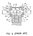
- FIG. 5 is a cross-sectional view of the welding device in FIG. 3.
- FIGs. 1 and 2 show a welding device according to one embodiment of the present invention.
- the welding device of the present invention comprises electrode position indicating means 6 for indicating an axial position of the welding electrode 22 with respect to the pipes 4, 5 to be welded.
- the welding device comprises a welding device body 8 and electrode position indicating means 6 installed on the welding device body 8.
- the welding device body 8 comprises a head unit 1, an electrode unit 2, a fixing clamp 3 for holding pipes 4, 5 to be welded, a cover plate 9 formed on the fixing clamp 3, and an installation portion 7 formed on the cover plate 9.
- the head unit 1 comprises a base 11, a first and a second extension portions 12, 12 respectively extending upwards from the two ends of the base 11.
- the electrode unit 2 comprises an arc-shaped rotation member 21 and a welding electrode 22 formed on the rotation member 21.
- the welding electrode 22 is formed to protrude from the inner side of the rotation member 21.
- the electrode unit 2 only moves along the circumferential direction of the pipe, and does not move in the axial and the radial directions of the pipe.
- the fixing clamp 3 comprises a first clamp 31 and a second clamp 32.
- the first clamp 31 is used to hold a pipe 4 to be welded, and comprises a first and a second holders 33, 34 for sandwiching the pipe 4 both top and bottom.
- the second clamp 32 is used to hold the other pipe 5 to be welded, and comprises a first and a second holders 37, 38 for sandwiching the pipe 5 both top and bottom.
- the first holders 33, 37 are respectively formed in a plate shape having a pipe-holding recessions 33a, 37a that are conformed to outer circumferences of the pipes 4, 5.
- the second holders 34, 38 are respectively formed in a plate shape having a pipe-holding recessions 34a, 38a that are conformed to outer circumferences of the pipes 4, 5.
- the cover plate 9 comprises a cover body 92 and a transparent protection plate 93.
- the cover body 92 includes a position-identification window 91 for identifying positions of butt edge surfaces 4a, 5a of the pipes 4, 5 to be welded, and the transparent protection plate 93 is used to cover the window 91.
- a laser passage opening 94 is formed on the protection plate 93 for guiding a laser beam (will be described later) emitted from the electrode position indicating means 6 into the welding device body 8.
- the axial position of the laser passage opening 94 is formed to be consistent with the axial position of the welding electrode 22.
- the installation portion 7 can be formed in a cylindrical shape with a bottom, and formed on the protection plate 93.
- a laser passage opening 71 is formed on the bottom of the installation portion 7 for guiding the laser beam (will be described later) emitted from the electrode position indicating means 6 into the welding device body 8.
- the shape of the laser passage opening 71 can be a circular or a regular polygon shape, etc.
- the inner diameter (the maximum diameter) of the laser passage opening 71 can be smaller than the shortest diameter of the laser beam emitted from the electrode position indicating means 6.
- the welding device body 8 can place the butt edge surfaces 4a, 5a of the pipes 4, 5 to be welded in a substantially sealed space S encompassed by the head unit 1, the first and the second extension portions 12, 13, the first and the second clamps 31, 32 and the cover plate 9.
- the electrode position indicating means 6 comprises a laser oscillator (means for irradiating an indicating light) 61 and an emitting unit 62 for emitting the laser beam from the laser oscillator 61.
- the laser bean can be irradiated to the pipes 4, 5 to be welded at an axial position corresponding to the welding electrode 22.
- the electrode position indicating means 6 can be fixed to the installation portion 7 via the emitting unit 62, or detachable to the installation portion 7.
- the aforementioned welding device can be an automatic welding device, which comprises driving means (not shown) and a control unit (not shown).
- the driving means can be a motor, etc. for rotationally driving the electrode unit 2 along the circumferential direction of the pipe, and the control unit is adapted to control a welding condition, such as a current value during the welding operation.
- the control unit previously sets a welding condition (current value, welding time, welding speed, atmosphere purge time, pulse time, etc.) according to a welding position (overhead position, flat position, horizontal position) varied by the rotation of the welding electrode 22.
- the pipes 4, 5 to be welded are placed between the extension portions 12, 13 of the head unit 1. At this time, as described below, whether the positions (positions in the axial direction of the pipe) of the butt edge surfaces 4a, 5a of the pipes 4, 5 to be welded and the position of the welding electrode 22 are consistent are identified.
- the laser oscillator 61 of the electrode position indicating means 6 is used to emit the laser beam L from the emitting unit 62.
- the laser beam L is irradiated from a direction substantially perpendicular to the axial direction of the pipes 4, 5 to be welded, passing through the laser passage opening 71 of the installation portion 7 and the laser passage opening 94 of the cover plate 9, and then to the pipes 4, 5 to be welded.
- the laser beam L is irradiated to the pipes 4, 5 to be welded at a position corresponding to the welding electrode 22.
- the pipes 4, 5 to be welded can be positioned according to a laser beam irradiation position 10.
- the pipes 4, 5 to be welded are moved along the axial direction to make the axial position of the butt edge surfaces 4a, 5a consistent with the laser beam irradiation position 10. In this way, the butt edge surfaces 4a, 5a are correctly consistent with the axial position of the welding electrode 22.
- the butt edge surfaces 4a, 5a and the laser bean irradiation position 10 can be affirmatively identified by eyes, even though in a substantially sealed space S encompassed by the base 11, the first and the second extension portions 12, 13, the first and the second clamps 31, 32 and the cover plate 9.
- the pipes 4, 5 to be welded are held by the first holders 33, 37 and the second holders 34, 38 of the clamps 31, 32. In this way, the pipes 4, 5 to be welded can be positioned under a condition that the butt edge surfaces 4a, 5a are butted to each other.
- the substantially-sealed space S of the welding device body 8 is filled with a sealing gas.
- the electrode unit 2 is rotated along the circumferential direction of the pipes 4, 5 to be welded, and the welding electrode 22 is used to weld the butt edge surfaces 4a, 5a over the entire circumference by arc welding.
- automatic welding of the pipes 4, 5 to be welded is preferred by optimizing the welding conditions, and via the control unit and driving the electrode unit 2.
- the above welding device comprises the electrode position indicating means 6 for irradiating the laser beam L to the pipes 4, 5 to be welded at a position corresponding to the welding electrode 22, the following effects can be achieved.
- the laser beam L corresponding to the position of the welding electrode 22 is directly irradiated to the pipes 4, 5 to be welded.
- the butt edge surfaces 4a, 5a can be easily and correctly placed at a position corresponding to the welding electrode 22. Therefore, the butt edge surfaces 4a, 5a can be precisely welded by the welding electrode 22, and defective welding can be avoided. In particular, even though for an I-shape butt welding which is difficult to determine whether a good quality welding is carried out, defective welding can be also avoided.
- the position detection accuracy is low and the welding position might deviate from the pipe end because the end position of the pipe is indirectly detected according to the amount of the laser beam reaching the receiving unit without irradiating the pipe.
- the laser beam irradiation position 10 can be easily identified and the positioning operation is easy because the pipes 4, 5 to be welded are positioned by irradiating the laser beam L.
- the pipes 4, 5 to be welded can be positioned according to a relative position between the butt edge surfaces 4a, 5a and the laser beam irradiation position 10 on the pipes 4, 5 to be welded, the relative position can be correctly controlled regardless of the operator's observation position. Therefore, even though the pipe position is hard to identify from a front position due to a limitation of working area, a correct positioning is possible.
- the welding device of the present invention is constructed by adding the installation portion 7 and the electrode position indicating means 6 to the conventional welding device shown in FIG. 3, the welding device of the present invention can be easily manufactured by including the installation portion 7 and the electrode positioning means 6 in the conventional welding device. Therefore, the cost can be reduced.
- the position of the laser beam L might deviate from its predetermined position due to a tiny shift of the installation position of the electrode position indicating means 6 with respect to the welding device body 8.
- an inexpensive laser pointer can be used as the laser oscillator 61, but in this case, the cross-sectional shape of the laser beam L irradiated to the pipes 4, 5 to be welded becomes an elliptical, rather than a circular. As a result, it is difficult to identify a correct position of the irradiated laser beam L.
- the inner diameter of the laser passage opening 71 is smaller than the shortest diameter of the laser beam (the emitting laser beam) L1 emitted from the laser oscillator 61, the position of the laser beam (irradiating laser beam) L2 irradiated to the pipes 4, 5 to be welded can still correspond to the laser passing opening 71 even though the position of the emitting laser beam L 1 is deviated. Hence, the irradiation position 10 of the irradiating laser beam L2 can be fixed.
- the shape of the irradiating laser beam L2 can be a shape corresponding to the laser passage opening 71 (for example, a circle), and thus the irradiating laser beam L2 can be easily identified. Therefore, the accuracy of positioning the pipes 4, 4 to be welded can be increased. In addition, even though an inexpensive laser pointer is used, the cost can be reduced because the irradiating laser beam L2 can be easily identified.
- the electrode position indicating means 5 can irradiate the laser beam to the pipes 4, 5 to be welded so as to make the laser beam irradiation position 10 to be consistent with the axial position of the welding electrode 22, the butt edge surfaces 4a, 5a and the axial position of welding electrode 22 can be consistent by matching the butt edge surfaces 4a, 5a with the laser beam irradiation position 10. Therefore, positioning the pipes 4, 5 to be welded can become easier.
- the position of the welding electrode 22 can be easily and visually identified and the pipes 4, 5 to be welded can be easily positioned because the position of the welding electrode 22 is directly indicated on the pipes 4, 5 to be welded by irradiating the laser beam.
- a plurality of electrode position indicating means 6 are not necessarily required for the welding device bodies 8 because the electrode position indicating means 6 is detachable from the welding device bodies 8.
- a plurality of welding device bodies 8 can share one common electrode position indicating means 6. Therefore, the welding device of the present invention is advantageous in reducing cost.
- the butt edge surfaces 4a, 5a can be easily and correctly arranged at the position corresponding to the welding electrode 22. Therefore, the butt edge surfaces 4a, 5a can be reliably welded and defective welding can be avoided.
- a plurality of clamps 31, 32 of various sizes in diameter can be prepared corresponding to pipes with different diameters.
- the clamps 31, 32 suitable to the pipes can be selected according to the size of the pipes to be welded. In this way, one common head unit 1 can be applied to pipes with different diameters.
- the pipes 4, 5 to be welded can be positioned after the pipes 4, 5 to be welded are linked by temporally fixing the pipes 4, 5 to each other by welding, etc. in advance.
- the embodiment described above shows an example of the electrode position indicating means 6 installed onto the installation portion 7 formed on the protection plate 93.
- the installation position of the electrode position indicating means 6 can be at any position that allows the laser beam to irradiate the pipes 4, 5 to be welded.
- the installation and the laser passage opening can be formed on the head unit 1.
- the installation portion 7 can formed in a structure capable of trimming its position by using position-adjusting screws, the position of the laser passage opening 71 can be optimized.
- the indicating light used in the present invention is not limited to the laser beam, other light sources can be also used.
- the above welding device comprises the electrode position indicating means for irradiating the indicating light to the pipes to be welded at a position corresponding to the welding electrode, the following effects can be achieved.
Landscapes
- Physics & Mathematics (AREA)
- Engineering & Computer Science (AREA)
- Optics & Photonics (AREA)
- Mechanical Engineering (AREA)
- Plasma & Fusion (AREA)
- Geometry (AREA)
- Butt Welding And Welding Of Specific Article (AREA)
- Arc Welding In General (AREA)
Abstract
Description
- This application claims the priority benefit of Japanese application serial no. 2003-149393, filed on May 27, 2003.
- This invention relates a welding device for butt welding pipes and a method thereof.
- When gas supply pipes are laid from a gas supply source in a gas yard to a point of use in a clean room, pipes are fixed in the gas yard, on walls of buildings, in pipe spaces in the buildings and under floor of the clean room, etc. Since the supply pipes are usually laid along the walls of rooms or buildings, a portion of the pipes are laid perpendicular or parallel to the other portion of the pipes. When the laying position of the pipes can be freely selected, for example, laying the pipes under the floor, most of the pipes are laid perpendicular or parallel to the partitions of the room. If a portion of the pipes is tilted towards the other portion of the pipes, there will be a loss of space and a difficult maintenance job, and furthermore, the appearance will be affected. In laying the supply pipes, it is better to consider a clearance of the pipes and a minimum clearance has to be reserved for welding at the pipe-laying site. Therefore, a common method is that pipe units linked by welding a plurality of pipes are made at a clean booth where the clearance can be controlled, and then the pipe units are welded according to a place to be laid.
- A Japanese Laid Open Publication 2000-334564 discloses a method for wilding pipes. In Japanese Laid Open Publication 2000-334564, a groove sensor, having an emitting unit and a receiving unit for a laser beam, is used to irradiate the laser beam to grooves formed at the end of a pipe. A groove shape is detected according to the laser beam that projects the groove and reaches the receiving section. Thereafter, a welding torch is arranged according to the position of the detected groove so as to weld the pipe.
- However, according to the method disclosed by Japanese Laid Open Publication 2000-334564, since the groove position is detected according to the laser beam that projects the groove and then reaches the receiving unit, the detection accuracy of the groove position is low and the welding position might be deviated from the pipe end.
- FIGs. 3 to 5 show an exemplary welding device used to weld a pipe. As shown, the welding device comprises a
head unit 1, anelectrode unit 2, afixing clamp 3 forholding pipes 4, 5 to be welded and acover plate 9 formed on thefixing clamp 3. Thehead unit 1 comprises abase 11, a first and asecond extension portions base 11. Theelectrode unit 2 comprises an arc-shaped rotation member 21 and awelding electrode 22 formed on therotation member 21. Thefixing clamp 3 comprises afirst clamp 31 and asecond clamp 32. Thefirst clamp 31 is used to hold one pipe 4 to be welded, and comprises a first and asecond holders second clamp 32 is used to hold theother pipe 5 to be welded, and comprises a first and asecond holders pipe 5 both top and bottom. Thefirst holders holding recessions pipes 4, 5. Thesecond holders holding recessions pipes 4, 5. Thecover plate 9 comprises acover body 92 and atransparent protection plate 93. Thecover body 92 includes a position-identification window 91 for identifying positions ofbutt edge surfaces pipes 4, 5 to be welded, and thetransparent protection plate 93 is used to cover thewindow 91. The welding device can place thebutt edge surfaces pipes 4, 5 to be welded in a substantially sealed space S encompassed by thehead unit 1, thefixing clamp 3 and thecover plate 9. - The method of using the above welding device to subject the
pipes 4, 5 to be welded to a butt welding is described below. As shown in FIG. 5, a distance a1 between the outer-rim surface of thefirst clamp 31 and thewelding electrode 22 is measured and a distance a2 between the outer-rim surface of thesecond clamp 32 and thewelding electrode 22 is measured. A position indicator (a marking line) 51 is formed by using a pen, etc. at a position apart from thebutt edge surface 4a of the pipe 4 to be welded by the distance a1. Also, another position indicator (a marking line) 51 is formed at a position apart from thebutt edge surface 5a of thepipe 5 to be welded by the distance a2. - The positions of the
position indicators 51 are respectively set to the outer-rim surface of the first and thesecond clamps pipes 4, 5 is arranged between theextension portions head unit 1 and then held by theclamps pipes 4, 5 to be welded are positioned in a manner that thebutt edge surfaces - For performing a good quality welding, it is important that positions (positions in the axial direction of the
pipes 4, 5, and refer to an axial position, hereinafter) of thebutt edge surfaces pipes 4,5 to be welded and thewelding electrode 22 are consistent. In the above method, the positioning of thepipes 4, 5 to be welded in the axial direction is performed by matching the position of theposition indicators 51 with theclamps pipes 4, 5 to be welded, whether or not the axial positions of thebutt edge surfaces welding electrode 22 are consistent with each other is identified through thewindow 91 by the unaided eyes. For performing a good welding, an axial position difference between thebutt edge surfaces welding electrode 22 is preferably equal to or less than a thickness half of thepipes 4, 5. In general, it is better that the axial position difference is equal to or less than 1mm, and preferably 0.5mm. After the positioning operation is performed, theelectrode unit 2 is rotated along the circumferential direction of thepipes 4, 5 to be welded and the entire circumferences of thebutt edge surfaces welding electrode 22. In this way, thepipes 4, 5 to be welded are subjected to butt welding. - The position of the welding electrode in the welding device is varied due to the device itself. The welding electrode is not located at the central position of the two clamps, and might be shifted from any one of the clamps. Therefore, the position indicator (the marking line) has to be formed every time to meet the direction of the welding device.
- However, when performing the welding at the pipe setting site, the
position indicator 51 is not easily formed at the correct position and with a suitable width because the working environment, such as the working area, is not suitable for welding. If theposition indicator 51 is not form at the correction position, the positioning accuracy of thepipes 4, 5 to be welded is low and thereby adversely affecting welding quality. In addition, if the position indicator is too thick, positioning thepipes 4, 5 to be welded might be incorrect. If theposition indicator 51 is too thin, it is very hard to visually identify and positioning of thepipes 4, 5 to be welded becomes difficult. - Additionally, there is usually a gap of about 0.5 to 3mm between the pipes and the electrode. Therefore, when identifying the axial position of the
butt edge surfaces window 91, the correct axial position has to be confirmed from a front direction of thepipes 4, 5 to be welded (a direction perpendicular to the axial direction). However, when the working area at the pipe setting site is limited, it is difficult to identify the axial position from the front direction. In addition, the identification might become difficult in a dark pipe setting site. Therefore, it is not easy to correctly and consistently position thebutt edge surfaces welding electrode 22. - If the axial directions of the
butt edge surfaces welding electrode 22 are shifted, the welding metal does not reach the inner surface of the pipes at thebutt edge surfaces butt edge surfaces - Since the appearance of the welded portion may be still of a good quality even though the welding was performed in a worse condition due to the position deviation, a worse welded pipe is difficult to distinguish. In addition, when the groove shape is a V or U shape, the target position of the electrode for a normal distance between the electrode and the pipe is different from target position of the electrode when the axial direction of the pipe is shifted. Therefore, the position deviation can be determined by monitoring an arc voltage. However, in a case of an I-shaped butt welding, since the distance between the pipe and the electrode does not vary even though a position deviation occurs, it is difficult to determine whether the welding is of good quality by monitoring the arc voltage. Therefore, a method capable of performing a good welding is desired. In particular, for a case of supply pipes used for high purity gas, toxic gas (Arsenic, etc.), combustible gas (silane, etc.) in the semiconductor manufacture, a precise welding is desired in order to prevent gas leakage or impurity invasion from the pipe.
- According to the foregoing description, an object of this invention is to provide a welding device and a welding method for performing a butt welding operation capable of easily and correctly making the position of the welding electrode and the position of the butt edge surfaces of the pipes to be consistent.
- According to the objects mentioned above, the present invention provides a welding device for butt welding two pipes to be welded. The welding device comprises a welding device body comprising an electrode unit with a welding electrode and a fixing clamp for holding the pipes to be welded; and electrode position indicating means for indicating a position of the welding electrode with respect to the pipes to be welded. The electrode position indicating means is capable of irradiating an indicating light to the pipes to be welded at the position corresponding to the welding electrode.
- In one embodiment of the invention, the electrode position indicating means is capable of irradiating the indicating light to the pipes to be welded so that an irradiation position is consistent with a position of the welding electrode in an axial direction of the pipe. In addition, the welding device body is constructed to place a portion of the pipes including butt edge surfaces in a substantially sealed space. Furthermore, the electrode position indicating means can be detachably installed to the welding device body.
- In one embodiment of the invention, a light passing opening is further formed on the welding device body for guiding the indicating light emitted from the electrode position indicating means into the welding device body, and an inner diameter of the light passing opening is smaller than the shortest diameter of the indicating light emitted from the electrode position indicating means.
- The present invention further provides a butt welding method for welding two pipes to be welded. The method comprises steps of irradiating an indicating light to the pipes to be welded at a position corresponding to a welding electrode; positioning the pipes to be welded according to a irradiation position of the indicating light; and welding the two pipes by using the welding electrode.
- While the specification concludes with claims particularly pointing out and distinctly claiming the subject matter which is regarded as the invention, the objects and features of the invention and further objects, features and advantages thereof will be better understood from the following description taken in connection with the accompanying drawings.
- FIG. 1 is a perspective view of a welding device according to one embodiment of the present invention.
- FIG. 2 is a cross-sectional view alone the line A-A of the welding device in FIG. 1.
- FIG. 3 is a perspective view showing a conventional welding device.
- FIG. 4 is an enlarged diagram showing main parts of the welding device in FIG. 3.
- FIG. 5 is a cross-sectional view of the welding device in FIG. 3.
- FIGs. 1 and 2 show a welding device according to one embodiment of the present invention. In the following description, elements common with the conventional welding device shown in FIGs. 3 to 5 are labeled with the same numeral, and their corresponding descriptions are omitted. At least one feature different from the conventional welding device is that the welding device of the present invention comprises electrode position indicating means 6 for indicating an axial position of the
welding electrode 22 with respect to thepipes 4, 5 to be welded. The welding device comprises awelding device body 8 and electrode position indicating means 6 installed on thewelding device body 8. Thewelding device body 8 comprises ahead unit 1, anelectrode unit 2, a fixingclamp 3 for holdingpipes 4, 5 to be welded, acover plate 9 formed on the fixingclamp 3, and aninstallation portion 7 formed on thecover plate 9. - The
head unit 1 comprises abase 11, a first and asecond extension portions base 11. Theelectrode unit 2 comprises an arc-shapedrotation member 21 and awelding electrode 22 formed on therotation member 21. Thewelding electrode 22 is formed to protrude from the inner side of therotation member 21. Theelectrode unit 2 only moves along the circumferential direction of the pipe, and does not move in the axial and the radial directions of the pipe. - The fixing
clamp 3 comprises afirst clamp 31 and asecond clamp 32. Thefirst clamp 31 is used to hold a pipe 4 to be welded, and comprises a first and asecond holders second clamp 32 is used to hold theother pipe 5 to be welded, and comprises a first and asecond holders pipe 5 both top and bottom. Thefirst holders recessions pipes 4, 5. Thesecond holders recessions pipes 4, 5. - The
cover plate 9 comprises acover body 92 and atransparent protection plate 93. Thecover body 92 includes a position-identification window 91 for identifying positions of butt edge surfaces 4a, 5a of thepipes 4, 5 to be welded, and thetransparent protection plate 93 is used to cover thewindow 91. Alaser passage opening 94 is formed on theprotection plate 93 for guiding a laser beam (will be described later) emitted from the electrode position indicating means 6 into thewelding device body 8. Preferably, the axial position of thelaser passage opening 94 is formed to be consistent with the axial position of thewelding electrode 22. - The
installation portion 7 can be formed in a cylindrical shape with a bottom, and formed on theprotection plate 93. Alaser passage opening 71 is formed on the bottom of theinstallation portion 7 for guiding the laser beam (will be described later) emitted from the electrode position indicating means 6 into thewelding device body 8. The shape of thelaser passage opening 71 can be a circular or a regular polygon shape, etc. The inner diameter (the maximum diameter) of thelaser passage opening 71 can be smaller than the shortest diameter of the laser beam emitted from the electrode position indicating means 6. Thewelding device body 8 can place the butt edge surfaces 4a, 5a of thepipes 4, 5 to be welded in a substantially sealed space S encompassed by thehead unit 1, the first and thesecond extension portions second clamps cover plate 9. - The electrode position indicating means 6 comprises a laser oscillator (means for irradiating an indicating light) 61 and an emitting
unit 62 for emitting the laser beam from thelaser oscillator 61. The laser bean can be irradiated to thepipes 4, 5 to be welded at an axial position corresponding to thewelding electrode 22. The electrode position indicating means 6 can be fixed to theinstallation portion 7 via the emittingunit 62, or detachable to theinstallation portion 7. - In addition, the aforementioned welding device can be an automatic welding device, which comprises driving means (not shown) and a control unit (not shown). The driving means can be a motor, etc. for rotationally driving the
electrode unit 2 along the circumferential direction of the pipe, and the control unit is adapted to control a welding condition, such as a current value during the welding operation. - Next, a butt welding method for welding the
pipes 4, 5 to be welded is described using the aforementioned welding device. The control unit previously sets a welding condition (current value, welding time, welding speed, atmosphere purge time, pulse time, etc.) according to a welding position (overhead position, flat position, horizontal position) varied by the rotation of thewelding electrode 22. - The
pipes 4, 5 to be welded are placed between theextension portions head unit 1. At this time, as described below, whether the positions (positions in the axial direction of the pipe) of the butt edge surfaces 4a, 5a of thepipes 4, 5 to be welded and the position of thewelding electrode 22 are consistent are identified. As shown in FIG. 2, thelaser oscillator 61 of the electrode position indicating means 6 is used to emit the laser beam L from the emittingunit 62. The laser beam L is irradiated from a direction substantially perpendicular to the axial direction of thepipes 4, 5 to be welded, passing through the laser passage opening 71 of theinstallation portion 7 and the laser passage opening 94 of thecover plate 9, and then to thepipes 4, 5 to be welded. The laser beam L is irradiated to thepipes 4, 5 to be welded at a position corresponding to thewelding electrode 22. - At this time, the
pipes 4, 5 to be welded can be positioned according to a laserbeam irradiation position 10. In other words, when the axial positions of the butt edge surfaces 4a, 5a and the laserbeam irradiation position 10 are not consistent, thepipes 4, 5 to be welded are moved along the axial direction to make the axial position of the butt edge surfaces 4a, 5a consistent with the laserbeam irradiation position 10. In this way, the butt edge surfaces 4a, 5a are correctly consistent with the axial position of thewelding electrode 22. The butt edge surfaces 4a, 5a and the laserbean irradiation position 10 can be affirmatively identified by eyes, even though in a substantially sealed space S encompassed by thebase 11, the first and thesecond extension portions second clamps cover plate 9. - Next, the
pipes 4, 5 to be welded are held by thefirst holders second holders clamps pipes 4, 5 to be welded can be positioned under a condition that the butt edge surfaces 4a, 5a are butted to each other. - Next, the substantially-sealed space S of the
welding device body 8 is filled with a sealing gas. Theelectrode unit 2 is rotated along the circumferential direction of thepipes 4, 5 to be welded, and thewelding electrode 22 is used to weld the butt edge surfaces 4a, 5a over the entire circumference by arc welding. During the welding process, automatic welding of thepipes 4, 5 to be welded is preferred by optimizing the welding conditions, and via the control unit and driving theelectrode unit 2. - Because the above welding device comprises the electrode position indicating means 6 for irradiating the laser beam L to the
pipes 4, 5 to be welded at a position corresponding to thewelding electrode 22, the following effects can be achieved. - First, the laser beam L corresponding to the position of the
welding electrode 22 is directly irradiated to thepipes 4, 5 to be welded. By positioning thepipes 4, 5 to be welded according to thelaser irradiation position 10, the butt edge surfaces 4a, 5a can be easily and correctly placed at a position corresponding to thewelding electrode 22. Therefore, the butt edge surfaces 4a, 5a can be precisely welded by thewelding electrode 22, and defective welding can be avoided. In particular, even though for an I-shape butt welding which is difficult to determine whether a good quality welding is carried out, defective welding can be also avoided. By contrast, in the conventional method of detecting the end position using a laser beam that projects the pipe and then reaches the receiving unit, the position detection accuracy is low and the welding position might deviate from the pipe end because the end position of the pipe is indirectly detected according to the amount of the laser beam reaching the receiving unit without irradiating the pipe. - Second, even though in a dark working environment, the laser
beam irradiation position 10 can be easily identified and the positioning operation is easy because thepipes 4, 5 to be welded are positioned by irradiating the laser beam L. - Third, because the
pipes 4, 5 to be welded can be positioned according to a relative position between the butt edge surfaces 4a, 5a and the laserbeam irradiation position 10 on thepipes 4, 5 to be welded, the relative position can be correctly controlled regardless of the operator's observation position. Therefore, even though the pipe position is hard to identify from a front position due to a limitation of working area, a correct positioning is possible. - Fourth, since the welding device of the present invention is constructed by adding the
installation portion 7 and the electrode position indicating means 6 to the conventional welding device shown in FIG. 3, the welding device of the present invention can be easily manufactured by including theinstallation portion 7 and the electrode positioning means 6 in the conventional welding device. Therefore, the cost can be reduced. - When positioning the
pipes 4, 5 to be welded, the position of the laser beam L might deviate from its predetermined position due to a tiny shift of the installation position of the electrode position indicating means 6 with respect to thewelding device body 8. In addition, an inexpensive laser pointer can be used as thelaser oscillator 61, but in this case, the cross-sectional shape of the laser beam L irradiated to thepipes 4, 5 to be welded becomes an elliptical, rather than a circular. As a result, it is difficult to identify a correct position of the irradiated laser beam L. - As shown in FIG. 2, in the above welding device, because the inner diameter of the
laser passage opening 71 is smaller than the shortest diameter of the laser beam (the emitting laser beam) L1 emitted from thelaser oscillator 61, the position of the laser beam (irradiating laser beam) L2 irradiated to thepipes 4, 5 to be welded can still correspond to thelaser passing opening 71 even though the position of the emittinglaser beam L 1 is deviated. Hence, theirradiation position 10 of the irradiating laser beam L2 can be fixed. Moreover, the shape of the irradiating laser beam L2 can be a shape corresponding to the laser passage opening 71 (for example, a circle), and thus the irradiating laser beam L2 can be easily identified. Therefore, the accuracy of positioning the pipes 4, 4 to be welded can be increased. In addition, even though an inexpensive laser pointer is used, the cost can be reduced because the irradiating laser beam L2 can be easily identified. - Because the electrode position indicating means 5 can irradiate the laser beam to the
pipes 4, 5 to be welded so as to make the laserbeam irradiation position 10 to be consistent with the axial position of thewelding electrode 22, the butt edge surfaces 4a, 5a and the axial position of weldingelectrode 22 can be consistent by matching the butt edge surfaces 4a, 5a with the laserbeam irradiation position 10. Therefore, positioning thepipes 4, 5 to be welded can become easier. - In the aforementioned welding device, although the butt edge surfaces 4a, 5a are set in the substantially-sealed space S, the position of the
welding electrode 22 can be easily and visually identified and thepipes 4, 5 to be welded can be easily positioned because the position of thewelding electrode 22 is directly indicated on thepipes 4, 5 to be welded by irradiating the laser beam. - Additionally, in some cases, it needs to prepare a plurality of
welding device bodies 8 according to the diameter of thepipes 4, 5 to be welded in order to correspond plural pipes with different diameters. In the above welding device, a plurality of electrode position indicating means 6 are not necessarily required for thewelding device bodies 8 because the electrode position indicating means 6 is detachable from thewelding device bodies 8. For example, a plurality ofwelding device bodies 8 can share one common electrode position indicating means 6. Therefore, the welding device of the present invention is advantageous in reducing cost. - According to the welding method described above, because the laser beam is irradiated to the
pipes 4, 5 to be welded at the position corresponding to thewelding electrode 22 and the welding is performed after thepipes 4, 5 to be welded are positioned according to thelaser irradiation position 10, the butt edge surfaces 4a, 5a can be easily and correctly arranged at the position corresponding to thewelding electrode 22. Therefore, the butt edge surfaces 4a, 5a can be reliably welded and defective welding can be avoided. - In addition, for welding pipes with different diameters, a plurality of
clamps common head unit 1 can be applied to pipes with different diameters. Furthermore, thepipes 4, 5 to be welded can be positioned after thepipes 4, 5 to be welded are linked by temporally fixing thepipes 4, 5 to each other by welding, etc. in advance. In particular, when the diameters of thepipes 4, 5 to be welded are large, because the occurrence of difference between the outer diameter of the pipe and the inner diameters of theclamps pipes 4, 5 to be welded is effective. Whether thepipes 4, 5 to be welded are temporally fixed can be determined according to whether thepipes 4, 5 to be welded are exactly positioned to the device by the fixingclamp 3. - The embodiment described above shows an example of the electrode position indicating means 6 installed onto the
installation portion 7 formed on theprotection plate 93. However, the installation position of the electrode position indicating means 6 can be at any position that allows the laser beam to irradiate thepipes 4, 5 to be welded. For example, the installation and the laser passage opening can be formed on thehead unit 1. Furthermore, if theinstallation portion 7 can formed in a structure capable of trimming its position by using position-adjusting screws, the position of thelaser passage opening 71 can be optimized. In addition, the indicating light used in the present invention is not limited to the laser beam, other light sources can be also used. - Because the above welding device comprises the electrode position indicating means for irradiating the indicating light to the pipes to be welded at a position corresponding to the welding electrode, the following effects can be achieved.
- (1) By positioning the pipes to be welded according to the indicating light irradiation position, the butt edge surfaces can be easily and correctly placed at a position corresponding to the welding electrode. Therefore, the butt edge surfaces can be precisely welded by the welding electrode, and defective welding can be avoided. In particular, the effect is obvious for an I-shape butt welding.
- (2) Because the pipes to be welded are positioned by irradiating the indicating light, the indicating light irradiation position can be easily identified, and the positioning operation is easy even in a dark working environment.
- (3) Because the pipes to be welded can be positioned according to a relative position between the butt edge surfaces and the indicating light irradiation position on the pipes to be welded, the relative position can be correctly controlled regardless of the operator's observation position. Therefore, even though the pipe position is hard to identify from a front position due to a limitation of working space, a correct positioning is possible.
-
- While the present invention has been described with a preferred embodiment, this description is not intended to limit our invention. Various modifications of the embodiment will be apparent to those skilled in the art. It is therefore contemplated that the appended claims will cover any such modifications or embodiments as fall within the true scope of the invention.
Claims (6)
- A welding device, for butt welding two pipes to be welded (4, 5), characterized in that the welding device comprises:wherein the electrode position indicating means (6) is capable of irradiating an indicating light (L) to the pipes to be welded (4, 5) at the position corresponding to the welding electrode (22).a welding device body (8), comprising an electrode unit (2) with a welding electrode (22) and a fixing clamp (3) for holding the pipes to be welded (4, 5); andelectrode position indicating means (6) for indicating a position of the welding electrode (22) with respect to the pipes to be welded (4, 5),
- The welding device of claim 1, characterized in that the electrode position indicating means (6) irradiates the indicating light (L) to the pipes to be welded (4, 5) in a manner that an irradiation position (10) is consistent with a position of the welding electrode (22) with respect to an axial direction of the pipe.
- The welding device of claim 1, characterized in that the welding device body (8) places butt edge surfaces (4a, 5a) of the pipes to be welded (4, 5) in a substantially sealed space (S).
- The welding device of claim 1, characterized in that the electrode position indicating means (6) is detachably installed to the welding device body (8).
- The welding device of claim 1, characterized in that a light passage opening (71) is formed on the welding device body (8) for guiding the indicating light emitted from the electrode position indicating means (6) into the welding device body (8), and an inner diameter of the light passage opening (71) is smaller than a shortest diameter of the indicating light (L1) emitted from the electrode position indicating means (6).
- A butt welding method for welding two pipes to be welded, characterized in that the butt welding method comprises steps ofirradiating an indicating light (L) to the pipes to be welded (4, 5) at a position corresponding to a welding electrode (22);positioning the pipes to be welded (4,5) according to a irradiation position (10) of the indicating light (L); andwelding the two pipes (4, 5) by using the welding electrode (22).
Applications Claiming Priority (2)
| Application Number | Priority Date | Filing Date | Title |
|---|---|---|---|
| JP2003149393A JP4130153B2 (en) | 2003-05-27 | 2003-05-27 | Welding equipment |
| JP2003149393 | 2003-05-27 |
Publications (1)
| Publication Number | Publication Date |
|---|---|
| EP1502693A1 true EP1502693A1 (en) | 2005-02-02 |
Family
ID=33447689
Family Applications (1)
| Application Number | Title | Priority Date | Filing Date |
|---|---|---|---|
| EP04012102A Withdrawn EP1502693A1 (en) | 2003-05-27 | 2004-05-21 | Welding device and method |
Country Status (6)
| Country | Link |
|---|---|
| US (1) | US6924452B2 (en) |
| EP (1) | EP1502693A1 (en) |
| JP (1) | JP4130153B2 (en) |
| KR (1) | KR100780011B1 (en) |
| CA (1) | CA2467952C (en) |
| TW (1) | TWI301430B (en) |
Cited By (3)
| Publication number | Priority date | Publication date | Assignee | Title |
|---|---|---|---|---|
| EP2027962A1 (en) * | 2007-08-17 | 2009-02-25 | Interforge Klee GmbH | Welding device and method for orbital welding of pipes |
| CN102922192A (en) * | 2012-10-17 | 2013-02-13 | 昆山吉海实业公司 | Method for operating container locking and driving plate and handle welding tool |
| CN110253192A (en) * | 2019-07-10 | 2019-09-20 | 金焊机械(太仓)有限公司 | A kind of stud welding fixture |
Families Citing this family (49)
| Publication number | Priority date | Publication date | Assignee | Title |
|---|---|---|---|---|
| US7713000B2 (en) * | 2005-04-20 | 2010-05-11 | Heerema Marine Contractors Nederland B.V. | Method and device for positioning ends of pipe sections relative to one another |
| US8335292B2 (en) * | 2006-10-19 | 2012-12-18 | General Electric Company | Jet pump diffuser weld repair device and method |
| US20080169277A1 (en) * | 2007-01-16 | 2008-07-17 | Illinois Tool Works Inc. | Lighted welding torch |
| US8026456B2 (en) * | 2007-02-20 | 2011-09-27 | Illinois Tool Works Inc. | TIG welding system and method |
| US20100051586A1 (en) * | 2008-05-06 | 2010-03-04 | Apparent Technologies, Inc. | Orbital welding system and methods of operations |
| EP2362817A4 (en) * | 2008-11-25 | 2017-09-06 | Justin V. Page | Welding apparatus and methods for welding |
| US20100219172A1 (en) * | 2009-03-02 | 2010-09-02 | Air Liquide Industrial U.S. Lp | Process For Reducing The Loss Of Backing Gas When Welding Pipe |
| FR2951390B1 (en) * | 2009-10-20 | 2012-01-06 | Areva Nc | IMPROVED SECURITY ELECTRODE CHANGING DEVICE |
| JP5727757B2 (en) * | 2009-12-25 | 2015-06-03 | 芝浦メカトロニクス株式会社 | Sealing can device |
| US7866532B1 (en) | 2010-04-06 | 2011-01-11 | United Launch Alliance, Llc | Friction stir welding apparatus, system and method |
| US8123104B1 (en) * | 2010-04-06 | 2012-02-28 | United Launch Alliance, Llc | Friction welding apparatus, system and method |
| US8141764B1 (en) | 2010-04-06 | 2012-03-27 | United Launch Alliance, Llc | Friction stir welding apparatus, system and method |
| CN102284819B (en) * | 2011-08-25 | 2014-05-21 | 沈阳飞机工业(集团)有限公司 | Flange fixing clamp welding tool |
| USD720973S1 (en) * | 2013-05-01 | 2015-01-13 | Watts Water Technologies, Inc. | Wand for fusing pipe |
| USD720972S1 (en) * | 2013-05-01 | 2015-01-13 | Watts Water Technologies, Inc. | Wand for fusing pipe |
| WO2016033568A1 (en) | 2014-08-29 | 2016-03-03 | Crc-Evans Pipeline International Inc. | Method and system for welding |
| US9821415B2 (en) | 2014-03-28 | 2017-11-21 | Crc-Evans Pipeline International, Inc. | Internal pipeline cooler |
| US10695876B2 (en) | 2013-05-23 | 2020-06-30 | Crc-Evans Pipeline International, Inc. | Self-powered welding systems and methods |
| US11767934B2 (en) | 2013-05-23 | 2023-09-26 | Crc-Evans Pipeline International, Inc. | Internally welded pipes |
| US10589371B2 (en) | 2013-05-23 | 2020-03-17 | Crc-Evans Pipeline International, Inc. | Rotating welding system and methods |
| US10040141B2 (en) | 2013-05-23 | 2018-08-07 | Crc-Evans Pipeline International, Inc. | Laser controlled internal welding machine for a pipeline |
| US10480862B2 (en) | 2013-05-23 | 2019-11-19 | Crc-Evans Pipeline International, Inc. | Systems and methods for use in welding pipe segments of a pipeline |
| EP3105001A4 (en) * | 2014-02-11 | 2017-03-01 | Magna International Inc. | Method of joining dissimilar materials |
| USD725449S1 (en) * | 2014-04-08 | 2015-03-31 | Watts Water Technologies, Inc. | Wand for fusing pipe |
| USD725448S1 (en) * | 2014-04-08 | 2015-03-31 | Watts Water Technologies, Inc. | Wand for fusing pipe |
| CN104191126A (en) * | 2014-08-20 | 2014-12-10 | 来宾华锡冶炼有限公司 | Hoop used for clamping spray gun main body and spray gun head of Ausmelt furnace during welding |
| CN104308416B (en) * | 2014-09-23 | 2016-03-02 | 浙江杨明斯金属制品有限公司 | A kind of fixture for welding diamond plate handrail |
| EP3165314A1 (en) * | 2015-11-06 | 2017-05-10 | Siegfried Plasch | Overlay welding method |
| JP6709638B2 (en) * | 2016-03-10 | 2020-06-17 | 日立造船株式会社 | Welding method of steel pipe and joint in steel pipe structure |
| US11458571B2 (en) * | 2016-07-01 | 2022-10-04 | Crc-Evans Pipeline International, Inc. | Systems and methods for use in welding pipe segments of a pipeline |
| US10668577B2 (en) | 2016-09-01 | 2020-06-02 | Crc-Evans Pipeline International Inc. | Cooling ring |
| CN107335900B (en) * | 2017-08-30 | 2023-12-01 | 国网浙江省电力有限公司台州供电公司 | a welding robot |
| PL3650157T3 (en) * | 2018-11-09 | 2023-10-02 | Illinois Tool Works, Inc. | ORBITAL WELDING DEVICE WITH SIMPLIFIED OPERATION |
| TWI716785B (en) * | 2018-12-14 | 2021-01-21 | 慶達科技股份有限公司 | Composite screw welding method |
| KR102096441B1 (en) * | 2019-03-28 | 2020-05-27 | 주식회사 서정테크놀로지 | Welding auxiliary apparatus |
| CN110369895A (en) * | 2019-07-15 | 2019-10-25 | 长兴云腾新能源科技有限公司 | A kind of net grade welding processing equipment of PFA knot for stainless steel semiconductor |
| KR102118844B1 (en) * | 2020-03-09 | 2020-06-03 | (주)세화테크놀로지 | Internal pipe purging system with improved pipe support stability |
| CN111687517A (en) * | 2020-04-29 | 2020-09-22 | 海洋石油工程(青岛)有限公司 | Process method for correcting linearity of stainless steel pipeline by welding |
| CN116262311A (en) * | 2021-12-13 | 2023-06-16 | 中国石油工程建设有限公司 | Transitional pipeline welding track |
| CN116275707A (en) * | 2021-12-13 | 2023-06-23 | 中国石油工程建设有限公司 | Inline pipe welding track |
| CN116262300A (en) * | 2021-12-13 | 2023-06-16 | 中国石油工程建设有限公司 | Inner rail closed small diameter pipe group butt welding machine |
| CN114985935B (en) * | 2022-02-15 | 2026-05-05 | 江苏福事特液压技术有限公司 | An integrated assembly and spot welding process |
| CN114669874B (en) * | 2022-03-04 | 2022-12-09 | 广东禅涛钢结构有限公司 | Laser welding equipment and method for longitudinal weld joint of pipe |
| CN116727979A (en) * | 2023-07-20 | 2023-09-12 | 江西熔岩汽配有限公司 | Welded pipe equipment for automobile suspension system |
| KR102628703B1 (en) * | 2023-10-06 | 2024-01-24 | 주식회사 에이치엘테크 | Fixing bracket assembly within the automatic welding device chamber |
| DE102024110344A1 (en) * | 2024-04-12 | 2025-10-16 | Illinois Tool Works Inc. | Orbital welding head |
| CN118081222B (en) * | 2024-04-26 | 2024-06-28 | 山东禾田动力科技有限公司 | Range extender shell rotary type welding device |
| CN118768689B (en) * | 2024-07-05 | 2025-06-20 | 河南省鸿达节能工程有限公司 | Arc welding device and method for concealed gas pipeline interface |
| CN119839495B (en) * | 2025-03-24 | 2025-06-20 | 山西省水利水电工程建设监理有限公司 | Welding device for large-diameter water diversion pipeline and use method |
Citations (3)
| Publication number | Priority date | Publication date | Assignee | Title |
|---|---|---|---|---|
| US5321259A (en) * | 1990-01-23 | 1994-06-14 | Oxford Sensor Technology Limited | Imaging device with prism scan element means |
| US5347101A (en) * | 1994-02-07 | 1994-09-13 | Mcdermott International, Inc. | Automatic tracking system for pipeline welding |
| US5837966A (en) * | 1997-07-23 | 1998-11-17 | Timmons, Jr.; John E. | Apparatus for weld head to pipe joint alignment for welding |
Family Cites Families (3)
| Publication number | Priority date | Publication date | Assignee | Title |
|---|---|---|---|---|
| US3534199A (en) * | 1968-11-12 | 1970-10-13 | Boeing Co | In-place tube welding torch |
| JPH0695010B2 (en) | 1990-09-05 | 1994-11-24 | 株式会社関西テック | Groove position detector for automatic pipe welding |
| US6559405B2 (en) * | 2001-06-12 | 2003-05-06 | General Electric Company | Positioning device for welding electrode |
-
2003
- 2003-05-27 JP JP2003149393A patent/JP4130153B2/en not_active Expired - Fee Related
-
2004
- 2004-02-23 TW TW093104402A patent/TWI301430B/en not_active IP Right Cessation
- 2004-03-30 KR KR1020040021408A patent/KR100780011B1/en not_active Expired - Fee Related
- 2004-05-19 US US10/850,421 patent/US6924452B2/en not_active Expired - Fee Related
- 2004-05-21 EP EP04012102A patent/EP1502693A1/en not_active Withdrawn
- 2004-05-21 CA CA002467952A patent/CA2467952C/en not_active Expired - Fee Related
Patent Citations (3)
| Publication number | Priority date | Publication date | Assignee | Title |
|---|---|---|---|---|
| US5321259A (en) * | 1990-01-23 | 1994-06-14 | Oxford Sensor Technology Limited | Imaging device with prism scan element means |
| US5347101A (en) * | 1994-02-07 | 1994-09-13 | Mcdermott International, Inc. | Automatic tracking system for pipeline welding |
| US5837966A (en) * | 1997-07-23 | 1998-11-17 | Timmons, Jr.; John E. | Apparatus for weld head to pipe joint alignment for welding |
Non-Patent Citations (1)
| Title |
|---|
| PATENT ABSTRACTS OF JAPAN vol. 0163, no. 68 (P - 1398) 7 August 1992 (1992-08-07) * |
Cited By (4)
| Publication number | Priority date | Publication date | Assignee | Title |
|---|---|---|---|---|
| EP2027962A1 (en) * | 2007-08-17 | 2009-02-25 | Interforge Klee GmbH | Welding device and method for orbital welding of pipes |
| CN102922192A (en) * | 2012-10-17 | 2013-02-13 | 昆山吉海实业公司 | Method for operating container locking and driving plate and handle welding tool |
| CN102922192B (en) * | 2012-10-17 | 2015-04-08 | 昆山吉海实业公司 | Method for operating container locking and driving plate and handle welding tool |
| CN110253192A (en) * | 2019-07-10 | 2019-09-20 | 金焊机械(太仓)有限公司 | A kind of stud welding fixture |
Also Published As
| Publication number | Publication date |
|---|---|
| JP4130153B2 (en) | 2008-08-06 |
| JP2004351434A (en) | 2004-12-16 |
| TWI301430B (en) | 2008-10-01 |
| CA2467952A1 (en) | 2004-11-27 |
| US20040238496A1 (en) | 2004-12-02 |
| TW200425990A (en) | 2004-12-01 |
| KR100780011B1 (en) | 2007-11-27 |
| KR20040101901A (en) | 2004-12-03 |
| CA2467952C (en) | 2009-03-31 |
| US6924452B2 (en) | 2005-08-02 |
Similar Documents
| Publication | Publication Date | Title |
|---|---|---|
| US6924452B2 (en) | Welding device and method | |
| EP1125695B1 (en) | Robotic laser pointer | |
| EP2333916B1 (en) | Sparkplug and manufacturing method therefor | |
| TWI801903B (en) | Control method of mobile welding robot, welding control device, mobile welding robot and welding system | |
| EP1707293B1 (en) | Method for measuring and adjusting the electrode for taper machining on an electrical discharge machine | |
| MXPA02006821A (en) | Control method of arc welding and arc welder. | |
| JP5445718B2 (en) | Weld joint butt position detection method, weld joint butt position detector, weld joint manufacturing method | |
| JP2008511449A (en) | Method for obtaining mutual position of laser processing beam axis and processing gas flow axis in laser processing apparatus, method for adjusting mutual position of laser processing beam axis and processing gas flow axis in laser processing apparatus, and apparatus in place of this method Laser processing apparatus having | |
| CN102481655A (en) | Device and method for automatic multi-head welding | |
| ITTO940433A1 (en) | AUTOMATIC CONTROL SYSTEM OF THE METHODS OF DEPOSIT AND ADDING OF THE WELDING MATERIAL IN THE ORBITAL WELDING PROCESSES | |
| HK1069145A (en) | Welding device and method | |
| JP2018001186A (en) | Device for measuring focal length in laser welding | |
| EP3182532B1 (en) | Inspection method and apparatus of spark plug insulator | |
| US10399187B2 (en) | System and method to locate and repair insert holes on a gas turbine component | |
| JP5381766B2 (en) | Welding method | |
| JP2008275482A (en) | Device for measuring interpass temperature, welding method using device for measuring interpass temperature | |
| JP7820253B2 (en) | Welding equipment and welding method | |
| JP2019158572A (en) | Method for producing gas sensor, method for securing sensor element protection cover, and welding device | |
| JP2007307612A (en) | Automatic welding method and automatic welding equipment, and reference tool used for automatic welding | |
| JPH0875895A (en) | Fuel rod circumference welding apparatus | |
| JP2006162344A (en) | Tool shape measuring apparatus and method | |
| JP5901285B2 (en) | Welding torch position calibration method and copy welding apparatus | |
| NL2002352C2 (en) | A method and apparatus for manufacturing a rail for a stairlift. | |
| KR101579211B1 (en) | The copy method of defection in welded zone | |
| JPH10216941A (en) | Position tracking control method of welding torch |
Legal Events
| Date | Code | Title | Description |
|---|---|---|---|
| PUAI | Public reference made under article 153(3) epc to a published international application that has entered the european phase |
Free format text: ORIGINAL CODE: 0009012 |
|
| AK | Designated contracting states |
Kind code of ref document: A1 Designated state(s): AT BE BG CH CY CZ DE DK EE ES FI FR GB GR HU IE IT LI LU MC NL PL PT RO SE SI SK TR |
|
| AX | Request for extension of the european patent |
Extension state: AL HR LT LV MK |
|
| RAP1 | Party data changed (applicant data changed or rights of an application transferred) |
Owner name: TAIYO NIPPON SANSO CORPORATION |
|
| 17P | Request for examination filed |
Effective date: 20050308 |
|
| RIN1 | Information on inventor provided before grant (corrected) |
Inventor name: KIMURA, YUTAKA |
|
| REG | Reference to a national code |
Ref country code: HK Ref legal event code: DE Ref document number: 1069145 Country of ref document: HK |
|
| AKX | Designation fees paid |
Designated state(s): DE FR GB SE |
|
| 17Q | First examination report despatched |
Effective date: 20070202 |
|
| STAA | Information on the status of an ep patent application or granted ep patent |
Free format text: STATUS: THE APPLICATION IS DEEMED TO BE WITHDRAWN |
|
| 18D | Application deemed to be withdrawn |
Effective date: 20091201 |
|
| REG | Reference to a national code |
Ref country code: HK Ref legal event code: WD Ref document number: 1069145 Country of ref document: HK |