EP1502028B1 - Liquid ring compressor - Google Patents
Liquid ring compressor Download PDFInfo
- Publication number
- EP1502028B1 EP1502028B1 EP03756128A EP03756128A EP1502028B1 EP 1502028 B1 EP1502028 B1 EP 1502028B1 EP 03756128 A EP03756128 A EP 03756128A EP 03756128 A EP03756128 A EP 03756128A EP 1502028 B1 EP1502028 B1 EP 1502028B1
- Authority
- EP
- European Patent Office
- Prior art keywords
- rotor
- compressor
- bearing
- compressor according
- liquid
- Prior art date
- Legal status (The legal status is an assumption and is not a legal conclusion. Google has not performed a legal analysis and makes no representation as to the accuracy of the status listed.)
- Expired - Lifetime
Links
- 239000007788 liquid Substances 0.000 title claims abstract description 49
- XLYOFNOQVPJJNP-UHFFFAOYSA-N water Substances O XLYOFNOQVPJJNP-UHFFFAOYSA-N 0.000 claims description 30
- 230000006835 compression Effects 0.000 claims description 13
- 238000007906 compression Methods 0.000 claims description 13
- 238000002347 injection Methods 0.000 claims description 10
- 239000007924 injection Substances 0.000 claims description 10
- 238000007789 sealing Methods 0.000 claims description 7
- 230000002093 peripheral effect Effects 0.000 claims description 5
- 238000010009 beating Methods 0.000 abstract 1
- 239000007789 gas Substances 0.000 description 27
- 230000003068 static effect Effects 0.000 description 8
- 238000013461 design Methods 0.000 description 5
- 238000000034 method Methods 0.000 description 4
- 239000012071 phase Substances 0.000 description 3
- 230000000903 blocking effect Effects 0.000 description 2
- 238000001816 cooling Methods 0.000 description 2
- 238000010586 diagram Methods 0.000 description 2
- 230000000694 effects Effects 0.000 description 2
- 239000003595 mist Substances 0.000 description 2
- 239000000243 solution Substances 0.000 description 2
- 239000003637 basic solution Substances 0.000 description 1
- 238000005452 bending Methods 0.000 description 1
- 238000004891 communication Methods 0.000 description 1
- 238000011161 development Methods 0.000 description 1
- 238000005265 energy consumption Methods 0.000 description 1
- 238000007667 floating Methods 0.000 description 1
- 239000012530 fluid Substances 0.000 description 1
- ZZUFCTLCJUWOSV-UHFFFAOYSA-N furosemide Chemical compound C1=C(Cl)C(S(=O)(=O)N)=CC(C(O)=O)=C1NCC1=CC=CO1 ZZUFCTLCJUWOSV-UHFFFAOYSA-N 0.000 description 1
- 239000004519 grease Substances 0.000 description 1
- 239000007791 liquid phase Substances 0.000 description 1
- 230000001050 lubricating effect Effects 0.000 description 1
- 238000011084 recovery Methods 0.000 description 1
- 238000011160 research Methods 0.000 description 1
Images


Classifications
-
- F—MECHANICAL ENGINEERING; LIGHTING; HEATING; WEAPONS; BLASTING
- F04—POSITIVE - DISPLACEMENT MACHINES FOR LIQUIDS; PUMPS FOR LIQUIDS OR ELASTIC FLUIDS
- F04C—ROTARY-PISTON, OR OSCILLATING-PISTON, POSITIVE-DISPLACEMENT MACHINES FOR LIQUIDS; ROTARY-PISTON, OR OSCILLATING-PISTON, POSITIVE-DISPLACEMENT PUMPS
- F04C19/00—Rotary-piston pumps with fluid ring or the like, specially adapted for elastic fluids
- F04C19/005—Details concerning the admission or discharge
- F04C19/008—Port members in the form of conical or cylindrical pieces situated in the centre of the impeller
-
- F—MECHANICAL ENGINEERING; LIGHTING; HEATING; WEAPONS; BLASTING
- F04—POSITIVE - DISPLACEMENT MACHINES FOR LIQUIDS; PUMPS FOR LIQUIDS OR ELASTIC FLUIDS
- F04C—ROTARY-PISTON, OR OSCILLATING-PISTON, POSITIVE-DISPLACEMENT MACHINES FOR LIQUIDS; ROTARY-PISTON, OR OSCILLATING-PISTON, POSITIVE-DISPLACEMENT PUMPS
- F04C19/00—Rotary-piston pumps with fluid ring or the like, specially adapted for elastic fluids
- F04C19/002—Rotary-piston pumps with fluid ring or the like, specially adapted for elastic fluids with rotating outer members
Landscapes
- Engineering & Computer Science (AREA)
- Mechanical Engineering (AREA)
- General Engineering & Computer Science (AREA)
- Structures Of Non-Positive Displacement Pumps (AREA)
- Flanged Joints, Insulating Joints, And Other Joints (AREA)
- Pharmaceuticals Containing Other Organic And Inorganic Compounds (AREA)
- Applications Or Details Of Rotary Compressors (AREA)
- Separating Particles In Gases By Inertia (AREA)
- Sealing Using Fluids, Sealing Without Contact, And Removal Of Oil (AREA)
- Compressor (AREA)
- Finger-Pressure Massage (AREA)
Abstract
Description
- The present invention relates to a compressor, in particular a liquid ring compressor.
- Most compressors work with approximate adiabatic process, i.e. without exchanging heat during the compression phase. In practice, e.g. a reciprocating compressor, emit quite a lot of heat, but it is only a small part of this heat which is emitted during compression, most of it is after, or in the end phase. A turbo compressor often has very close adiabatic process.
- Some, a bit more special compressors can work very close to isothermal, i.e. the heat which is generated is continuously led away and the temperature is kept unchanged. Examples of these are water driven ejectors and liquid ring compressors, where both are frequently used with vacuum. A screw compressor with oil injection works polytropic, i.e. somewhere between adiabatic and isothermal.
- The isothermal process requires less energy supplied than the adiabatic. The difference increase rapidly with increasing pressure difference, as shown in the diagram in figure 1. This shows theoretical values, calculated for air based upon formula for ideal gas. Air and gases which in a state which is not in the proximity of the critical point, behave very close to ideal.
- For most objectives it is not desirable with hot gas after compression, and from this and the energy consumption, the isothermal process is preferred in theory.
- When this, despite the above, is not employed today, the reason can be found in that existing isothermal or close isothermal compressors have too large hydraulic and dynamic losses. It is an exception for vacuum pumps which in reality is liquid compressors with high pressure difference, p2/p1, but with little pressure height, p2-pl. These can operate with low peripheral speeds on the liquid ring. Another problem is in the technical challenge to be able to remove heat continuously during compression.
- Within vacuum both ejector and water ring compressors are frequently used. An ejector exploit the mass speed in a water jet in which the cross section expands and thereby can pull another medium with it. The ejector transform dynamic pressure to static pressure. However, an ejector system has relatively high losses in pump, in nozzle, by impact and friction. Ejectors are rarely used to anything else than the vacuum field. Within prior art the water ring compressor is closest to the compressor according to the present invention.
- A liquid ring compressor consists mainly of an impeller which rotates eccentric in an outer enclosure together with a ring of water which the centrifugal force keeps in place against the periphery. The inlet is normally positioned as an opening in one or both of the end walls of the enclosure where the gas is drawn into the gaps of the impeller. Accordingly, it is arranged openings in the end walls on the pressure side, where the compressed gas is pushed out. All the types can have stationary commutators arranged centrally within the rotor where inlet and discharge happens radially.
- Liquid ring compressor does not transform the energy in the water in the same way as the ejector. The static pressure in the ring of water remains constant. The ring of water acts as a piston in every cell of the rotor. The principle for an ordinary liquid ring compressor is shown in figure 2, where a ring of
liquid 23 rotates eccentric in astationary enclosure 22, drive by arotor 21 where the gap between the impeller will draw in gas on one side of a revolution and compress the gas on the other. - The static pressure in the ring of water has to be the same as the compression pressure, otherwise the water will be pressed out of the cell, i.e. the water ring will be deformed. Thereby it is given that a certain pressure height, p2-pl, require a minimum centrifugal force. A liquid ring compressor usually has considerably higher pressure height and therefore requires higher speed of rotation than a vacuum pump.
- The highest loss of friction in a conventional water ring compressor arise when the rotor is touching the wall of the enclosure. The clearing must here be very small, something which involves the water against the enclosure's periphery to have the same speed as the impeller tips of the rotor. Furthermore it must be very little clearance between the sides of the rotor and the enclosure. Also in these gaps there will be high frictions.
- Generally the friction losses increase with a square of the speed increase, and in practice the water ring compressor looses level of energy in relation to energy in relation to an adiabatic compressor even at relatively low pressure ratios.
- Without these friction losses, the liquid ring compressor has many advantages. It is very simple and can be one stage up to relatively high pressure ratios.
- It is apparent that if that the enclosure around the ring of water rotated together with this, the hydraulic friction losses would be minimal. Thus, such a compressor would for normal pressure ratios could exploit the isothermal energy advantages almost in full.
- An earlier suggestion disclosed with an outer, rotating cylinder tried to solve the problem of friction, without this leading to a feasible solution.
US 5 100 300 andUS 5 370 502 describes liquid ring compressor with a cylinder which floats on a film of liquid or gas between the cylinder and the outer stationary enclosure. By floating on a liquid film, it is doubtful whether it would be achieved any reduction in the friction, and with gas it would probably not be possible to achieve sufficient bearing capacity and stability, such that the cylinder do not touch the enclosure. - In a later patent,
US 5 395 215 , from the same firm, it is suggested a bearing of this cylinder in an outer enclosure, where a number of rollers are inserted in the wall of the enclosure where the cylinder is supported by the rollers. This do not seem realistic with the actual rotational speeds the rollers will achieve. A subsequent patent,US 5 653 582 , returns back to fluids as the peripheral bearing for the rotating cylinder and suggestion to the basic solution. -
US 5 251 593 discloses as the previous application that it is an intricate problem to get to, in relation to each other, eccentric bearings in combination with a stationary canals for the inlet and discharge of the gas. This publication indicates a bearing of the outer rotating cylinder on one side and the rotor on the opposite side, where a stationary plate close to the open end of the rotor has canals for inlet and discharge. It is mainly two decisive weaknesses with this design. The first is the one-sided bearing this solution gives, where the bearing load becomes uneven and too high. At the same time large axial thrust forces arise. The other weakness is the problems with achieving a reasonable gas tight sealing between the outer rotating cylinder, and the plate where the inlet and discharge canals are positioned in a circular plate, inlaid in the open end of the rotor. It would here be gas leaks backwards from cell to cell and in addition out through the circular gap between the stationary plate and the rotor. The principle is unrealistic for practical purposes. - Despite many studies and suggestions over many years, it evidently has not been possible to reach a design which fulfil the requirements to function satisfactory. Thus at present there exists no liquid ring compressor with such co-rotating rotor. The above mentioned publications indicates that one has been tied up to the starting point for a rotor and communicator system like those in conventional vacuum pumps and compressors for relatively low pressure, with the above mentioned limitations in speed. This is reflected in relatively wide rotors with communicator on each side, which lead to long bearing distance and high bearing loads. In a compressor with liquid ring in the outer co-rotor, the geometry will be wrong, which will lead to bearing relationship which is unsuitable for existing bearing types. With communicator on each side it becomes four sections with gaps where there exists leakage from the zones on the pressure side.
- The compressor according to the present invention has the objective to solve this problem which up to know has prevented a water ring compressor to exploit the above mentioned advantages with a co-rotor for the liquid ring. Another objective is to achieve almost isothermal compression with a new, very efficient direct injection of liquid into the gas during the whole compression stage.
- Water as injection liquid has very good thermal properties, and is desirable to use with those gases which allow this. But, as for pumps and the like, the design for a liquid compressor with a co-rotor require a distinct division between water and the bearing of the co-rotor. From the development of screw compressors with water injection it is known and it has been problems with sealing on the pressure side of the screws. Firstly, water has small to little lubricating effect on the sealing which must have relatively high pressure towards the axle and therefore high wear. Furthermore, water penetrates easily through even the finest gaps, and especially high pressure. Below it will be evident that the compressor according to the present invention solves the sealing problem by eliminating the reasons for them. The aforementioned objectives will be satisfied with the liquid ring compressor according to present invention as it is defined in the attached claims.
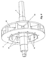
- The invention will now be described, by way of example, with reference to the accompanying drawings, in which figure I shows a diagram with theoretical energy needs independence of pressure relation ship, figure 2 shows schematic the principle for a liquid ring compressor, figure 3 a liquid ring compressor according to the present invention in a divided longitudinal view, figure 4 is a cross section of figure 4, figure 5 shows the compressor as mounted, sectioned design, figure 6 shows details of the rotor, figures 7a and 7b shows details of the communicator, and figure 8 shows details of the bearing to the co-rotor, seals and the system for airing of the zones at the bearings.
- The main parts in figure 3 consists of two
enclosures co-rotors 3 and 4, arotor 6 and arotor axle 5, acommunicator 7, twobearings 11 forco-rotors 3 and 4 and twobearings 12 for therotor axle 5 as well as theaxles inner bearings 12. On figure 4 a sector I-II with suction, a compression and injection sector II-III and a sector III-I for gas discharge in the clockwise direction. In the sector II-III liquid is injected from the communicator directly into the rotor cells and the compression and cooling of the gas in the cells. - With the largely reduced friction in the water ring due to the co-rotor, is it possible to make the rotor considerable narrower at the same time that the discharge volume is compensated with a considerable increase in speed. Thereby the inner pressure in the water ring is increased and the compressor can deliver with very high pressure.
- A short rotor get little bending force from the gas pressure and is thereby allowed to be fixed to a flange on its axle only at one end wall and thereby being able to have a simple commutator in the entire width of the rotor. It is then only created two leakage gap between the commutator and the rotor. These gaps are the only place where leakage from the pressure side will find place. It can leak actually to both sides from the gap and along the periphery from the pressure discharge against the inlet, especially in the direction of rotation. Even in very small gaps, pure gas without liquid will with the present pressure be able to leak in considerable amounts, with smaller amounts deliver and lower efficiency as a result.
- The surface of the
rotor 6 on the inside towards the commutator is at itsends 63 smooth, with interweavingcanal openings 62 to each individual cell. On figure 7a and 7b it is shown that the commutator has a row ofgrooves 71 in the opposite side sections. The grooves are under liquid pressure from theliquid canal 74 which thereby is blocking for gas leakages in the actual direction. - The liquid ring compressor according to the present invention could be designed with hydro dynamic bearing for the co-rotor. These could then be lubricated and cooled with the same liquid which was used for injection. But with the starting point with necessary axle diameter and speed, research shows however that the friction losses in such bearings then will be very high and some of the advantages with a co-rotor are lost. With higher pressure the bearing size increases further and the losses in them become unacceptable.
- On the other hand the same relationship seems to be acceptable for relatively large ball or roller bearings, but at the same time this leads to new problems around the bearing sealing. Bearings with integrated seals can not operate close to the necessary speeds and there do not exist any static seals which allows this, or that will achieve acceptable lifetime. Labyrinth seals however are touch-free and can operate with high speeds, but do not give any static sealing. These seals assume there are no differential pressures across the seal.
- To prevent differential pressure across the bearing a co-rotor is aired to the compressor enclosure through the
holes 81 as shown in figure 8. For air pressure compressors the enclosure is in turn aired to atmosphere or is by compression of other gases to prevent discharge, aired to the inlet, and thereby it will not be a differential pressure across the bearing of the co-rotor. Blocking liquid which leaks from the gap between the commutator and the rotor will during operation be projected out into the liquid ring and will not be able to reach the bearings for the co-rotor. Thus, the design only needs a static bearing seal during the stopping phase, where the danger for splashing water against the seals is apparent when the water ring collapses due to lack of centrifugal force. In conventional water ring compressors it is earlier known to be used lip seals as disclosed inUS 4 747 752 . In that case, however, it is dealt with a drive axle which has a relatively small diameter and low peripheral speed. As mentioned above the speed relationship for the co-rotor becomes critical with regards to wear. - This is led to the need for designing and completely
new lip seal 82, shown in more detail in figure 8, which solves the problem in a relatively simple manner. The seal rotates together with the outer ring of thebearing 11. Thelip 83 is relatively ductile and at standstill and under start and stop cycle it will rest against the axle and seal statically, but when the speed and centrifugal forces increases, it is projected outwards and get a clearance sx so it does not touch the axle during operation. This is shown in the cross section A and B of figure 8. - It is evident that the lip during operation places itself against the edge of the openings in the co-rotor and walls so it is relatively small movements the lip bends from being in contact with the axle until it is not. This give little fatigue effect even with frequent start and stop.
- The seal is in other words static at low speeds and seems dynamic at higher speeds, where its purpose is only to prevent bearing grease to be projected out. Bearing of the co-rotor will with this system get about the same surrounding relationship and security as if they operated in air.
- It is the diameter on the bearing of the rotor and the eccentricity between the rotors which decide the diameter on the bearing axles of the co-rotor because the bearing of the rotor as shown is inserted in these. The load on the bearing of the rotor becomes the same as for the co-rotor. To withstand this load, at the same time as giving smallest possible dimensions for the axle to the co-rotor, so-called needle bearings are used for the rotor. The purpose and the necessity by integrating the bearing of the rotor in the axle of the co-rotor, is to achieve short as possible bearing distance which give smallest axle diameter. For the bearing for this axle the peripheral speed allows ordinary static seals, and the bearing can be lubricated by oil.
- To prevent the creating of trapped gas pockets in the cells of the
rotor 61, are these as shown in figure 6, circular inwards towards the canal openings. Along the periphery of the commutator in the sector of this where the compression finds place, it is drilled a number ofholes 75 which are in communication with theinner liquid canal 74 which has a pressure similar to the delivery pressure of the compressor. Through these holes liquid is injected directly into the cells of the rotor. These jets are hit of the rims of the inlet and discharge canals of the cells with high velocity and frequency, and the liquid pulverises so it is transformed into a liquid mist inside the cell. The mist is projected out towards the water ring, but is continuously renewed by new jets so there is a flow outwardly. The density of holes can increase towards the end of the compression sector to compensate for a falling differential pressure between the liquid and the gas. - The commutator is fixed to the one,
stationary axle 8 for the co-rotor. The axle connects the canals of the commutator with the respective inlet and discharge for gas and injection liquid. - When the compressor according to the present invention is used for other gases than air, e.g. cooling system or in a petrochemical plant, it can be useful to use the actual gas in the liquid phase for injection and as liquid ring.
- At an expected, reasonably lower energy need than for a turbo compressor the compressor will according to the present invention be very suitable as compressor in a gas turbine plant which operates with relatively high pressure relationship. The air from this will indeed in contrast to the turbo compressor, be cold, but it is necessary to note that the heat which the turbo compressor delivers is taken out of the axle of the turbine and reduces the output effect accordingly at the same time as the warm air to do not make it possible for heat recovery from the turbine exhaust. By use of the compressor according to the invention, the air from the compressor can be heat exchanged with the exhaust gas and almost reach the same temperatures as after a turbine compressor.
Claims (10)
- Liquid ring compressor, characterized by an eccentric inner rotor (6) supported in axles (8, 9) to an outer co-rotor (3) for the liquid ring, the bearing of the co-rotors (11) being outside the same axles and is enclosed on each side in an enclosure where on each side of the bearing (11) a rotating lip seal (82) is arranged which the lip (83) of which lip seal (82) abuts the axles (8, 9) at low speed, and which lip (83) at high speed is projected out due to centrifugal forces and lifts itself from the axles, where through holes (81) through the co-rotor's sidewalls and bearing enclosure, being provided which volume within the liquid ring is aired to the surrounding enclosure (1), so that no differential pressure is created across the bearings and the seals of the bearings.
- Compressor according to claim 1, characterized by that the rotor (6) in the periphery has a number of cells (61) with half cylindrical shape where the arc is turned towards the centre.
- Compressor according to claim 1-2, characterized by the cells (61) of the rotor (6) has radial canal openings (62) on each side surrounded of a circular smooth section (63) for sealing against a stationary commutator (7) placed in the centre of the rotor.
- Compressor according to claim 1-3, characterized by that it from hole (75) in the commutator (7) in the compression sector is injected liquid where liquid beams crush of the rims of the canal opening (62) to the cells (61) of the rotor.
- Compressor according to claim 1-4, characterized by that the commutator (7) on each side has peripheral grooves (71), where injection liquid exist under pressure and inhibit gas leaks.
- Compressor according to claim 1-5, characterized by that the periphery of the commutator (7) is outside the co-rotors bearing seals so that leaking water from the gap between the commutator and the rotor is projected out in the liquid ring without passing the bearing seals.
- Compressor according to claim 1-6, characterized by that the bearings (11) for the co-rotor are of ball or roller bearings types.
- Compressor according to claim 1-6, characterized by that bearings (11) are slide bearings, including hydrodynamic types.
- Use of a compressor according to claim 1-8 as an air compressor and water compatible gasses where water is used as injection liquid.
- Use of a compressor according to claim 1-9 as a compressor in a gas turbine plant.
Applications Claiming Priority (3)
| Application Number | Priority Date | Filing Date | Title |
|---|---|---|---|
| NO20021844A NO316638B1 (en) | 2002-04-19 | 2002-04-19 | Vaeskeringkompressor |
| NO20021844 | 2002-04-19 | ||
| PCT/NO2003/000128 WO2003102423A1 (en) | 2002-04-19 | 2003-04-16 | Liquid ring compressor |
Publications (2)
| Publication Number | Publication Date |
|---|---|
| EP1502028A1 EP1502028A1 (en) | 2005-02-02 |
| EP1502028B1 true EP1502028B1 (en) | 2008-01-23 |
Family
ID=19913538
Family Applications (1)
| Application Number | Title | Priority Date | Filing Date |
|---|---|---|---|
| EP03756128A Expired - Lifetime EP1502028B1 (en) | 2002-04-19 | 2003-04-16 | Liquid ring compressor |
Country Status (11)
| Country | Link |
|---|---|
| US (2) | US20050271520A1 (en) |
| EP (1) | EP1502028B1 (en) |
| JP (1) | JP2005534843A (en) |
| CN (1) | CN1656317A (en) |
| AT (1) | ATE384877T1 (en) |
| AU (1) | AU2003263670A1 (en) |
| DE (1) | DE60318841T2 (en) |
| ES (1) | ES2300607T3 (en) |
| NO (1) | NO316638B1 (en) |
| PT (1) | PT1502028E (en) |
| WO (1) | WO2003102423A1 (en) |
Families Citing this family (3)
| Publication number | Priority date | Publication date | Assignee | Title |
|---|---|---|---|---|
| US10669850B2 (en) | 2016-12-22 | 2020-06-02 | Brian Blackwell | Impeller-type liquid ring compressor |
| GB2565579B (en) * | 2017-08-17 | 2020-03-04 | Edwards Ltd | A pump and method of pumping a fluid |
| DE102017215080A1 (en) * | 2017-08-29 | 2019-02-28 | Friedrich-Alexander-Universität Erlangen-Nürnberg | Liquid ring pump |
Family Cites Families (13)
| Publication number | Priority date | Publication date | Assignee | Title |
|---|---|---|---|---|
| US1668532A (en) * | 1924-09-08 | 1928-05-01 | W L Stewart | Rotary machine |
| US2771860A (en) * | 1950-08-22 | 1956-11-27 | Werner P Falk | Hydraulic machine |
| IN166621B (en) * | 1986-01-09 | 1990-06-23 | Warman Int Ltd | |
| US4747752A (en) * | 1987-04-20 | 1988-05-31 | Somarakis, Inc. | Sealing and dynamic operation of a liquid ring pump |
| GB8912505D0 (en) * | 1989-05-31 | 1989-07-19 | Pedersen John R C | Improvements in or relating to liquid ring machines |
| US5197863A (en) * | 1990-12-28 | 1993-03-30 | The Nash Engineering Company | Bearing fluid distribution systems for liquid ring pumps with rotating lobe liners |
| US5100300A (en) * | 1990-12-28 | 1992-03-31 | The Nash Engineering Company | Liquid ring pumps having rotating lobe liners with end walls |
| US5295794A (en) * | 1993-01-14 | 1994-03-22 | The Nash Engineering Company | Liquid ring pumps with rotating liners |
| DE4343551A1 (en) * | 1993-12-20 | 1995-06-22 | Siemens Ag | Liquid ring vacuum pump |
| US5395215A (en) * | 1994-07-26 | 1995-03-07 | The Nash Engineering Company | Supports for rotatable housing of liquid ring pumps |
| CN1079503C (en) * | 1995-08-16 | 2002-02-20 | 西门子公司 | Ring liquid compression engine |
| US5653582A (en) * | 1995-09-26 | 1997-08-05 | The Nash Engineering Company | Fluid bearing pad arrangement for liquid ring pump systems |
| DE19758340A1 (en) * | 1997-12-22 | 1999-07-08 | Gardner Denver Wittig Gmbh | Multi-flow liquid ring pump |
-
2002
- 2002-04-19 NO NO20021844A patent/NO316638B1/en unknown
-
2003
- 2003-04-16 CN CN03812088.7A patent/CN1656317A/en active Pending
- 2003-04-16 AU AU2003263670A patent/AU2003263670A1/en not_active Abandoned
- 2003-04-16 ES ES03756128T patent/ES2300607T3/en not_active Expired - Lifetime
- 2003-04-16 JP JP2004509281A patent/JP2005534843A/en active Pending
- 2003-04-16 EP EP03756128A patent/EP1502028B1/en not_active Expired - Lifetime
- 2003-04-16 AT AT03756128T patent/ATE384877T1/en not_active IP Right Cessation
- 2003-04-16 WO PCT/NO2003/000128 patent/WO2003102423A1/en active IP Right Grant
- 2003-04-16 US US10/511,753 patent/US20050271520A1/en not_active Abandoned
- 2003-04-16 PT PT03756128T patent/PT1502028E/en unknown
- 2003-04-16 DE DE60318841T patent/DE60318841T2/en not_active Expired - Fee Related
-
2008
- 2008-06-30 US US12/164,908 patent/US20080260543A1/en not_active Abandoned
Also Published As
| Publication number | Publication date |
|---|---|
| DE60318841T2 (en) | 2009-01-22 |
| NO20021844D0 (en) | 2002-04-19 |
| PT1502028E (en) | 2008-05-06 |
| ES2300607T3 (en) | 2008-06-16 |
| ATE384877T1 (en) | 2008-02-15 |
| DE60318841D1 (en) | 2008-03-13 |
| CN1656317A (en) | 2005-08-17 |
| NO316638B1 (en) | 2004-03-15 |
| US20080260543A1 (en) | 2008-10-23 |
| WO2003102423A1 (en) | 2003-12-11 |
| AU2003263670A1 (en) | 2003-12-19 |
| NO20021844L (en) | 2003-10-20 |
| EP1502028A1 (en) | 2005-02-02 |
| JP2005534843A (en) | 2005-11-17 |
| US20050271520A1 (en) | 2005-12-08 |
Similar Documents
| Publication | Publication Date | Title |
|---|---|---|
| EP0631650B1 (en) | Liquid ring pumps with rotating liners | |
| CN101418796B (en) | Screw fluid machine | |
| JP4081274B2 (en) | Screw compressor into which water is injected | |
| US20080260543A1 (en) | Liquid ring compressor | |
| EP0432287B1 (en) | Rotary engine | |
| CN111043317A (en) | Novel dynamic pressure damping seal structure | |
| KR20080047295A (en) | Vane pump | |
| US9004857B2 (en) | Barrel-shaped centrifugal compressor | |
| KR101138389B1 (en) | Screw rotor type vaccum pump with built in motor | |
| CN209838754U (en) | Compressor with gas bearing | |
| KR101013124B1 (en) | Structure for leak prevention Turbo Compressor | |
| JPS6332997B2 (en) | ||
| RU2518785C2 (en) | Two-cycle centrifugal compressor | |
| KR102617553B1 (en) | Balance device of multistage pump | |
| JP5931696B2 (en) | Rotating machine | |
| CN219366328U (en) | Wide-performance end-suction multistage centrifugal pump | |
| CN213088230U (en) | Self-circulation mechanical seal type roots blower | |
| KR200265014Y1 (en) | Mechanical seal for pump | |
| CN1492152A (en) | Screw groove non-contact leak-less mechanical seal system for centrifugal pump | |
| JPS6332998B2 (en) | ||
| KR100390489B1 (en) | Structure for reducing gas leakage of turbo compressor | |
| JP2001153089A (en) | Vacuum pump | |
| KR100495637B1 (en) | Rotary Fluid Movers | |
| CA2003789C (en) | Displacement-type rotary system steam-turbine engine | |
| CN114893434A (en) | Non-contact sealing method for low-pressure rotary fluid pump |
Legal Events
| Date | Code | Title | Description |
|---|---|---|---|
| PUAI | Public reference made under article 153(3) epc to a published international application that has entered the european phase |
Free format text: ORIGINAL CODE: 0009012 |
|
| 17P | Request for examination filed |
Effective date: 20041119 |
|
| AK | Designated contracting states |
Kind code of ref document: A1 Designated state(s): AT BE BG CH CY CZ DE DK EE ES FI FR GB GR HU IE IT LI LU MC NL PT RO SE SI SK TR |
|
| AX | Request for extension of the european patent |
Extension state: AL LT LV MK |
|
| GRAP | Despatch of communication of intention to grant a patent |
Free format text: ORIGINAL CODE: EPIDOSNIGR1 |
|
| RIN1 | Information on inventor provided before grant (corrected) |
Inventor name: KAROLIUSSEN, HILBERG |
|
| GRAS | Grant fee paid |
Free format text: ORIGINAL CODE: EPIDOSNIGR3 |
|
| GRAA | (expected) grant |
Free format text: ORIGINAL CODE: 0009210 |
|
| AK | Designated contracting states |
Kind code of ref document: B1 Designated state(s): AT BE BG CH CY CZ DE DK EE ES FI FR GB GR HU IE IT LI LU MC NL PT RO SE SI SK TR |
|
| REG | Reference to a national code |
Ref country code: GB Ref legal event code: FG4D |
|
| REG | Reference to a national code |
Ref country code: CH Ref legal event code: EP |
|
| REG | Reference to a national code |
Ref country code: IE Ref legal event code: FG4D |
|
| REF | Corresponds to: |
Ref document number: 60318841 Country of ref document: DE Date of ref document: 20080313 Kind code of ref document: P |
|
| REG | Reference to a national code |
Ref country code: PT Ref legal event code: SC4A Free format text: AVAILABILITY OF NATIONAL TRANSLATION Effective date: 20080422 |
|
| REG | Reference to a national code |
Ref country code: SE Ref legal event code: TRGR |
|
| REG | Reference to a national code |
Ref country code: GR Ref legal event code: EP Ref document number: 20080401077 Country of ref document: GR |
|
| REG | Reference to a national code |
Ref country code: ES Ref legal event code: FG2A Ref document number: 2300607 Country of ref document: ES Kind code of ref document: T3 |
|
| PG25 | Lapsed in a contracting state [announced via postgrant information from national office to epo] |
Ref country code: CH Free format text: LAPSE BECAUSE OF FAILURE TO SUBMIT A TRANSLATION OF THE DESCRIPTION OR TO PAY THE FEE WITHIN THE PRESCRIBED TIME-LIMIT Effective date: 20080123 Ref country code: FI Free format text: LAPSE BECAUSE OF FAILURE TO SUBMIT A TRANSLATION OF THE DESCRIPTION OR TO PAY THE FEE WITHIN THE PRESCRIBED TIME-LIMIT Effective date: 20080123 Ref country code: LI Free format text: LAPSE BECAUSE OF FAILURE TO SUBMIT A TRANSLATION OF THE DESCRIPTION OR TO PAY THE FEE WITHIN THE PRESCRIBED TIME-LIMIT Effective date: 20080123 |
|
| PGFP | Annual fee paid to national office [announced via postgrant information from national office to epo] |
Ref country code: ES Payment date: 20080418 Year of fee payment: 6 |
|
| REG | Reference to a national code |
Ref country code: CH Ref legal event code: PL |
|
| PG25 | Lapsed in a contracting state [announced via postgrant information from national office to epo] |
Ref country code: AT Free format text: LAPSE BECAUSE OF FAILURE TO SUBMIT A TRANSLATION OF THE DESCRIPTION OR TO PAY THE FEE WITHIN THE PRESCRIBED TIME-LIMIT Effective date: 20080123 |
|
| ET | Fr: translation filed | ||
| PG25 | Lapsed in a contracting state [announced via postgrant information from national office to epo] |
Ref country code: SI Free format text: LAPSE BECAUSE OF FAILURE TO SUBMIT A TRANSLATION OF THE DESCRIPTION OR TO PAY THE FEE WITHIN THE PRESCRIBED TIME-LIMIT Effective date: 20080123 Ref country code: BE Free format text: LAPSE BECAUSE OF FAILURE TO SUBMIT A TRANSLATION OF THE DESCRIPTION OR TO PAY THE FEE WITHIN THE PRESCRIBED TIME-LIMIT Effective date: 20080123 |
|
| PGFP | Annual fee paid to national office [announced via postgrant information from national office to epo] |
Ref country code: IT Payment date: 20080421 Year of fee payment: 6 Ref country code: BG Payment date: 20080418 Year of fee payment: 6 Ref country code: PT Payment date: 20080424 Year of fee payment: 6 |
|
| PG25 | Lapsed in a contracting state [announced via postgrant information from national office to epo] |
Ref country code: CZ Free format text: LAPSE BECAUSE OF FAILURE TO SUBMIT A TRANSLATION OF THE DESCRIPTION OR TO PAY THE FEE WITHIN THE PRESCRIBED TIME-LIMIT Effective date: 20080123 Ref country code: DK Free format text: LAPSE BECAUSE OF FAILURE TO SUBMIT A TRANSLATION OF THE DESCRIPTION OR TO PAY THE FEE WITHIN THE PRESCRIBED TIME-LIMIT Effective date: 20080123 Ref country code: SK Free format text: LAPSE BECAUSE OF FAILURE TO SUBMIT A TRANSLATION OF THE DESCRIPTION OR TO PAY THE FEE WITHIN THE PRESCRIBED TIME-LIMIT Effective date: 20080123 |
|
| PGFP | Annual fee paid to national office [announced via postgrant information from national office to epo] |
Ref country code: DE Payment date: 20080624 Year of fee payment: 6 Ref country code: NL Payment date: 20080430 Year of fee payment: 6 Ref country code: SE Payment date: 20080414 Year of fee payment: 6 |
|
| PG25 | Lapsed in a contracting state [announced via postgrant information from national office to epo] |
Ref country code: RO Free format text: LAPSE BECAUSE OF FAILURE TO SUBMIT A TRANSLATION OF THE DESCRIPTION OR TO PAY THE FEE WITHIN THE PRESCRIBED TIME-LIMIT Effective date: 20080123 Ref country code: MC Free format text: LAPSE BECAUSE OF NON-PAYMENT OF DUE FEES Effective date: 20080430 |
|
| PLBE | No opposition filed within time limit |
Free format text: ORIGINAL CODE: 0009261 |
|
| STAA | Information on the status of an ep patent application or granted ep patent |
Free format text: STATUS: NO OPPOSITION FILED WITHIN TIME LIMIT |
|
| 26N | No opposition filed |
Effective date: 20081024 |
|
| PGFP | Annual fee paid to national office [announced via postgrant information from national office to epo] |
Ref country code: GB Payment date: 20080416 Year of fee payment: 6 |
|
| PG25 | Lapsed in a contracting state [announced via postgrant information from national office to epo] |
Ref country code: EE Free format text: LAPSE BECAUSE OF FAILURE TO SUBMIT A TRANSLATION OF THE DESCRIPTION OR TO PAY THE FEE WITHIN THE PRESCRIBED TIME-LIMIT Effective date: 20080123 |
|
| PG25 | Lapsed in a contracting state [announced via postgrant information from national office to epo] |
Ref country code: IE Free format text: LAPSE BECAUSE OF NON-PAYMENT OF DUE FEES Effective date: 20080416 |
|
| PGFP | Annual fee paid to national office [announced via postgrant information from national office to epo] |
Ref country code: GR Payment date: 20080429 Year of fee payment: 6 |
|
| PG25 | Lapsed in a contracting state [announced via postgrant information from national office to epo] |
Ref country code: CY Free format text: LAPSE BECAUSE OF FAILURE TO SUBMIT A TRANSLATION OF THE DESCRIPTION OR TO PAY THE FEE WITHIN THE PRESCRIBED TIME-LIMIT Effective date: 20080123 |
|
| EUG | Se: european patent has lapsed | ||
| GBPC | Gb: european patent ceased through non-payment of renewal fee |
Effective date: 20090416 |
|
| NLV4 | Nl: lapsed or anulled due to non-payment of the annual fee |
Effective date: 20091101 |
|
| REG | Reference to a national code |
Ref country code: FR Ref legal event code: ST Effective date: 20091231 |
|
| PG25 | Lapsed in a contracting state [announced via postgrant information from national office to epo] |
Ref country code: DE Free format text: LAPSE BECAUSE OF NON-PAYMENT OF DUE FEES Effective date: 20091103 |
|
| PG25 | Lapsed in a contracting state [announced via postgrant information from national office to epo] |
Ref country code: NL Free format text: LAPSE BECAUSE OF NON-PAYMENT OF DUE FEES Effective date: 20091101 |
|
| PG25 | Lapsed in a contracting state [announced via postgrant information from national office to epo] |
Ref country code: FR Free format text: LAPSE BECAUSE OF NON-PAYMENT OF DUE FEES Effective date: 20091222 Ref country code: GB Free format text: LAPSE BECAUSE OF NON-PAYMENT OF DUE FEES Effective date: 20090416 |
|
| PGFP | Annual fee paid to national office [announced via postgrant information from national office to epo] |
Ref country code: FR Payment date: 20080430 Year of fee payment: 6 |
|
| REG | Reference to a national code |
Ref country code: ES Ref legal event code: FD2A Effective date: 20090417 |
|
| PG25 | Lapsed in a contracting state [announced via postgrant information from national office to epo] |
Ref country code: GR Free format text: LAPSE BECAUSE OF NON-PAYMENT OF DUE FEES Effective date: 20091104 |
|
| PG25 | Lapsed in a contracting state [announced via postgrant information from national office to epo] |
Ref country code: ES Free format text: LAPSE BECAUSE OF NON-PAYMENT OF DUE FEES Effective date: 20090417 Ref country code: LU Free format text: LAPSE BECAUSE OF NON-PAYMENT OF DUE FEES Effective date: 20080416 Ref country code: HU Free format text: LAPSE BECAUSE OF FAILURE TO SUBMIT A TRANSLATION OF THE DESCRIPTION OR TO PAY THE FEE WITHIN THE PRESCRIBED TIME-LIMIT Effective date: 20080724 |
|
| PG25 | Lapsed in a contracting state [announced via postgrant information from national office to epo] |
Ref country code: TR Free format text: LAPSE BECAUSE OF FAILURE TO SUBMIT A TRANSLATION OF THE DESCRIPTION OR TO PAY THE FEE WITHIN THE PRESCRIBED TIME-LIMIT Effective date: 20080123 |
|
| PG25 | Lapsed in a contracting state [announced via postgrant information from national office to epo] |
Ref country code: PT Free format text: LAPSE BECAUSE OF NON-PAYMENT OF DUE FEES Effective date: 20101018 |
|
| PG25 | Lapsed in a contracting state [announced via postgrant information from national office to epo] |
Ref country code: IT Free format text: LAPSE BECAUSE OF NON-PAYMENT OF DUE FEES Effective date: 20090416 Ref country code: BG Free format text: LAPSE BECAUSE OF FAILURE TO SUBMIT A TRANSLATION OF THE DESCRIPTION OR TO PAY THE FEE WITHIN THE PRESCRIBED TIME-LIMIT Effective date: 20090430 |
|
| PG25 | Lapsed in a contracting state [announced via postgrant information from national office to epo] |
Ref country code: SE Free format text: LAPSE BECAUSE OF NON-PAYMENT OF DUE FEES Effective date: 20090417 |