EP1501552B1 - Mr-signal emitting coatings - Google Patents
Mr-signal emitting coatings Download PDFInfo
- Publication number
- EP1501552B1 EP1501552B1 EP02790131A EP02790131A EP1501552B1 EP 1501552 B1 EP1501552 B1 EP 1501552B1 EP 02790131 A EP02790131 A EP 02790131A EP 02790131 A EP02790131 A EP 02790131A EP 1501552 B1 EP1501552 B1 EP 1501552B1
- Authority
- EP
- European Patent Office
- Prior art keywords
- poly
- hydrogel
- dtpa
- acid
- chelate
- Prior art date
- Legal status (The legal status is an assumption and is not a legal conclusion. Google has not performed a legal analysis and makes no representation as to the accuracy of the status listed.)
- Expired - Lifetime
Links
Images


Classifications
-
- A—HUMAN NECESSITIES
- A61—MEDICAL OR VETERINARY SCIENCE; HYGIENE
- A61K—PREPARATIONS FOR MEDICAL, DENTAL OR TOILETRY PURPOSES
- A61K49/00—Preparations for testing in vivo
- A61K49/06—Nuclear magnetic resonance [NMR] contrast preparations; Magnetic resonance imaging [MRI] contrast preparations
- A61K49/08—Nuclear magnetic resonance [NMR] contrast preparations; Magnetic resonance imaging [MRI] contrast preparations characterised by the carrier
- A61K49/085—Nuclear magnetic resonance [NMR] contrast preparations; Magnetic resonance imaging [MRI] contrast preparations characterised by the carrier conjugated systems
-
- A—HUMAN NECESSITIES
- A61—MEDICAL OR VETERINARY SCIENCE; HYGIENE
- A61K—PREPARATIONS FOR MEDICAL, DENTAL OR TOILETRY PURPOSES
- A61K49/00—Preparations for testing in vivo
- A61K49/06—Nuclear magnetic resonance [NMR] contrast preparations; Magnetic resonance imaging [MRI] contrast preparations
- A61K49/08—Nuclear magnetic resonance [NMR] contrast preparations; Magnetic resonance imaging [MRI] contrast preparations characterised by the carrier
- A61K49/10—Organic compounds
- A61K49/12—Macromolecular compounds
- A61K49/126—Linear polymers, e.g. dextran, inulin, PEG
- A61K49/128—Linear polymers, e.g. dextran, inulin, PEG comprising multiple complex or complex-forming groups, being either part of the linear polymeric backbone or being pending groups covalently linked to the linear polymeric backbone
-
- A—HUMAN NECESSITIES
- A61—MEDICAL OR VETERINARY SCIENCE; HYGIENE
- A61K—PREPARATIONS FOR MEDICAL, DENTAL OR TOILETRY PURPOSES
- A61K49/00—Preparations for testing in vivo
- A61K49/06—Nuclear magnetic resonance [NMR] contrast preparations; Magnetic resonance imaging [MRI] contrast preparations
- A61K49/18—Nuclear magnetic resonance [NMR] contrast preparations; Magnetic resonance imaging [MRI] contrast preparations characterised by a special physical form, e.g. emulsions, microcapsules, liposomes
- A61K49/1803—Semi-solid preparations, e.g. ointments, gels, hydrogels
-
- A—HUMAN NECESSITIES
- A61—MEDICAL OR VETERINARY SCIENCE; HYGIENE
- A61L—METHODS OR APPARATUS FOR STERILISING MATERIALS OR OBJECTS IN GENERAL; DISINFECTION, STERILISATION OR DEODORISATION OF AIR; CHEMICAL ASPECTS OF BANDAGES, DRESSINGS, ABSORBENT PADS OR SURGICAL ARTICLES; MATERIALS FOR BANDAGES, DRESSINGS, ABSORBENT PADS OR SURGICAL ARTICLES
- A61L29/00—Materials for catheters, medical tubing, cannulae, or endoscopes or for coating catheters
- A61L29/08—Materials for coatings
- A61L29/085—Macromolecular materials
-
- A—HUMAN NECESSITIES
- A61—MEDICAL OR VETERINARY SCIENCE; HYGIENE
- A61L—METHODS OR APPARATUS FOR STERILISING MATERIALS OR OBJECTS IN GENERAL; DISINFECTION, STERILISATION OR DEODORISATION OF AIR; CHEMICAL ASPECTS OF BANDAGES, DRESSINGS, ABSORBENT PADS OR SURGICAL ARTICLES; MATERIALS FOR BANDAGES, DRESSINGS, ABSORBENT PADS OR SURGICAL ARTICLES
- A61L29/00—Materials for catheters, medical tubing, cannulae, or endoscopes or for coating catheters
- A61L29/14—Materials characterised by their function or physical properties, e.g. lubricating compositions
- A61L29/18—Materials at least partially X-ray or laser opaque
-
- A—HUMAN NECESSITIES
- A61—MEDICAL OR VETERINARY SCIENCE; HYGIENE
- A61L—METHODS OR APPARATUS FOR STERILISING MATERIALS OR OBJECTS IN GENERAL; DISINFECTION, STERILISATION OR DEODORISATION OF AIR; CHEMICAL ASPECTS OF BANDAGES, DRESSINGS, ABSORBENT PADS OR SURGICAL ARTICLES; MATERIALS FOR BANDAGES, DRESSINGS, ABSORBENT PADS OR SURGICAL ARTICLES
- A61L31/00—Materials for other surgical articles, e.g. stents, stent-grafts, shunts, surgical drapes, guide wires, materials for adhesion prevention, occluding devices, surgical gloves, tissue fixation devices
- A61L31/08—Materials for coatings
- A61L31/10—Macromolecular materials
-
- A—HUMAN NECESSITIES
- A61—MEDICAL OR VETERINARY SCIENCE; HYGIENE
- A61L—METHODS OR APPARATUS FOR STERILISING MATERIALS OR OBJECTS IN GENERAL; DISINFECTION, STERILISATION OR DEODORISATION OF AIR; CHEMICAL ASPECTS OF BANDAGES, DRESSINGS, ABSORBENT PADS OR SURGICAL ARTICLES; MATERIALS FOR BANDAGES, DRESSINGS, ABSORBENT PADS OR SURGICAL ARTICLES
- A61L31/00—Materials for other surgical articles, e.g. stents, stent-grafts, shunts, surgical drapes, guide wires, materials for adhesion prevention, occluding devices, surgical gloves, tissue fixation devices
- A61L31/14—Materials characterised by their function or physical properties, e.g. injectable or lubricating compositions, shape-memory materials, surface modified materials
- A61L31/18—Materials at least partially X-ray or laser opaque
-
- G—PHYSICS
- G01—MEASURING; TESTING
- G01R—MEASURING ELECTRIC VARIABLES; MEASURING MAGNETIC VARIABLES
- G01R33/00—Arrangements or instruments for measuring magnetic variables
- G01R33/20—Arrangements or instruments for measuring magnetic variables involving magnetic resonance
- G01R33/28—Details of apparatus provided for in groups G01R33/44 - G01R33/64
- G01R33/285—Invasive instruments, e.g. catheters or biopsy needles, specially adapted for tracking, guiding or visualization by NMR
Definitions
- This invention relates in general to coatings that emit magnetic resonance signals and in particular, to such coatings containing paramagnetic metal ions, and to a process for coating devices and implants with such coatings so that these devices are readily visualized in magnetic resonance images during diagnostic or therapeutic procedures done in conjunction with magnetic resonance imaging (MRI).
- MRI magnetic resonance imaging
- MR magnetic resonance
- Endovascular therapy refers to a general class of minimally-invasive interventional (or surgical) techniques which are used to treat a variety of diseases such as vascular disease and tumors.
- endovascular therapies utilize the vascular system to access and treat the disease.
- the vascular system is accessed by way of a peripheral artery or vein such as the common femoral vein or artery.
- a small incision is made in the groin and either the common femoral artery or vein is punctured.
- An access sheath is then inserted and through the sheath a catheter is introduced and advanced over a guide-wire to the area of interest.
- a therapeutic device e.g., balloon, stent, coil
- an agent e.g., embolizing agent, anti-vasospasm agent
- the catheter functions as a conduit and ensures the accurate and localized delivery of the therapeutic device or agent to the region of interest.
- its delivery system is withdrawn, i.e., the catheter is withdrawn, the sheath removed and the incision closed.
- the duration of an average endovascular procedure is about 3 hours, although difficult cases may take more than 8 hours. Traditionally, such procedures have been performed under x-ray fluoroscopic guidance.
- MR-guided procedures include the ability to acquire three-dimensional images. In contrast, most x-ray angiography systems can only acquire a series of two-dimensional projection images. MR has clear advantages when multiple projections or volume reformatting are required in order to understand the treatment of complex three-dimensional vascular abnormalities, such as arterial-venous malformations (AVMs) and aneurysms. Furthermore, MR is sensitive to measurement of a variety of "functional" parameters including temperature, blood flow, tissue perfusion, diffusion, and brain activation. This additional diagnostic information, which, in principle, can be obtained before, during and immediately after therapy, cannot be acquired by x-ray fluoroscopy alone. It is likely that once suitable MR-based endovascular procedures have been developed, the next challenge will be to integrate this functional information with conventional anatomical imaging and device tracking.
- RF radio-frequency
- the position of the device is computed from MR signals generated by these coils and detected by MR imager. This information is superimposed on an anatomical "road map" image of the area in which the device is being used.
- the advantages of active tracking include excellent temporal and spatial resolution. However, active methods allow visualization of only a discrete point(s) on the device. Typically, only the tip of the device is “active", i.e., visualized. Although it is possible to incorporate multiple RF coils (4-6 on typical clinical MR systems) into a device, it is still impossible to determine position at more than a few discrete points along the device. While this may be acceptable for tracking rigid biopsy needles, this is a significant limitation for tracking flexible devices such as those used in endovascular therapy. Furthermore, intravascular heating due to RF-induced currents is a concern with active methods.
- One technique for passive tracking is based on the fact that some devices do not emit a detectable MR signal and also cause no artifacts in the MR image. This results in such a device being seen as an area of signal loss or signal void in the MR images. By tracking or following the signal void, the position and motion of such a device can be determined.
- One advantage of passive tracking methods over active methods is that they do allow "visualization" of the entire length of a device. Since air, cortical bone and flowing blood are also seen in MR images as areas of signal voids, the use of signal void is generally not appropriate for tracking devices used in interventional MR.
- Another technique of passive tracking utilizes the fact that some materials cause a magnetic susceptibility artifact (either signal enhancement or signal loss) that causes a signal different from the tissue in which they are located.
- Some catheters braided with metal, some stents and some guide-wires are examples of such devices.
- susceptibility artifacts One problem with the use of these techniques based on susceptibility artifacts is the fact that those used for localization of the device does not correspond precisely with the size of the device. This makes precise localization difficult.
- WO-A-9960920 discloses a magnetic resonance imaging system comprising a magnetic resonance device for generating a magnetic resonance image of a target object in an imaging region; and an instrument for use with the target object in the imaging region, said instrument including a body sized for use in the target object and a polymeric-paramagnetic ion complex coating thereon in which said complex is represented by the formula: P-X-L-M n+ wherein P is a polymer, X is a surface functional group, L is a chelate, M is a paramagnetic ion an n is an integer that is 2 or greater.
- WO-A1-02/22186 relates to a process for making a lubricious medical device capable of being detected by magnetic resonance imaging, said process comprising:
- WO-A1-01/81460 relates to a biomaterial based on a hydrophilic polymer exhibiting a specific signal in magnetic resonance imaging, and a method for preparing same.
- the biomaterial is loaded with superparamagnetic iron oxide particles so as to exhibit a signal different from that of the non-loaded biomaterial and that of the biological medium wherein it is placed for one or several types of MRI sequences.
- the present invention provides a process for coating medical devices so that the devices are readily visualized, particularly, in T 1 weighted magnetic resonance images. Because of the high signal caused by the coating, the entirety of the coated devices can be readily visualized during, e.g., an endovascular procedure.
- a magnetic resonance (MR) signal-emitting coating which includes a paramagnetic metal ion-containing polymer complex and a method of visualizing medical devices in magnetic resonance imaging, which includes the step of coating the devices with the paramagnetic-ion containing polymer.
- the present invention provides a coating for visualizing medical devices in magnetic resonance imaging, comprising a complex of formula (I): P-X-L-M n+ (I) wherein P is a polymer, X is a surface functional group, L is a chelate, M is a paramagnetic ion and n is an integer that is 2 or greater.
- the polymer P may be a base polymer from which a medical device is made.
- the invention is a coating for visualizing medical devices in magnetic resonance imaging, comprising a complex of formula (II): P - X - J - L - M n+ (II) wherein P is a polymer, X is a surface functional group, L is a chelate, M is a paramagnetic ion, n is an integer that is 2 or greater and J is the linker or spacer molecule.
- the polymer P may be a base polymer from which a medical device is made.
- the invention is a magnetic resonance imaging system which includes a magnetic resonance device for generating a magnetic resonance image of a target object (as defined hereinafter) in an imaging region (as defined hereinafter) and an instrument for use with the target object in the imaging region.
- the instrument includes a body sized for use in the target object and a polymeric-paramagnetic ion complex coating in which the complex is represented by formula (I) through (V) as set forth below in the detailed description.
- the invention is a method for visualizing medical devices in magnetic resonance imaging which includes the steps of (a) coating the medical device with a polymeric-paramagnetic complex of formula (I) through (V) as set forth below in the detailed description; (b) positioning the device within a target object; and (c) imaging the target object and coated device.
- the invention provides a method of making a medical device magnetic-resonance imageable.
- the method comprises providing a coating on the medical device in which a paramagnetic-metal ion/chelate complex is encapsulated by a first hydrogel.
- a chelate of the paramagnetic-metal-ion/chelate complex is linked to a functional group, and the functional group is an amino group or a carboxyl group.
- the paramagnetic-metal ion may, but need not be, designated as M n+ , wherein M is a lanthanide or a transition metal which is iron, manganese, chromium, cobalt or nickel, and n is an integer that is 2 or greater.
- the medical device may be made from a solid-base polymer, and the method further comprises treating the solid-base polymer to yield the functional group thereon. Accordingly, the complex is covalently linked to the medical device.
- the functional group may be a functional group of a polymer that is not covalently linked to the medical device.
- the functional group may be a functional group of a second hydrogel. The first and second hydrogels may be the same or different.
- a cross-linker may also be used to cross-link the first hydrogel with the solid-base polymer, the polymer not covalently linked to the medical device or the second hydrogel, depending upon the embodiment.
- the invention provides a medical device capable of being magnetic-resonance imaged.
- the device comprises a chelate linked to a functional group.
- the functional group may be an amino or a carboxyl group.
- the device also comprises a paramagnetic-metal ion that is coordinated with the chelate to form a paramagnetic-metal-ion/chelate complex.
- the device also comprises a first hydrogel that encapsulates the paramagnetic-metal-ion/chelate complex.
- the paramagnetic-metal ion may, but need not be, designated as M n+ , wherein M is a lanthanide or a transition metal which is iron, manganese, chromium, cobalt or nickel, and n is an integer that is 2 or greater.
- M is a lanthanide or a transition metal which is iron, manganese, chromium, cobalt or nickel
- n is an integer that is 2 or greater.
- the medical device may be made from a solid-base polymer, and the functional group is a functional group on the solid-base polymer. Accordingly, the complex is covalently linked to the medical device.
- the functional group may be a functional group of a polymer that is not covalently linked to the medical device.
- the functional group may be a functional group of a second hydrogel.
- the first and second hydrogels may be the same or different.
- a cross-linker may also be used to cross-link the first hydrogel with the solid-base poly
- the invention provides a method of reducing the mobility of paramagnetic metal ion/chelate complexes covalently linked to a solid polymer substrate of a medical device.
- This method includes providing a medical device having paramagnetic metal ion/chelate complexes covalently linked to the solid polymer substrate of the medical device.
- the method also includes encapsulating at least a portion of the medical device having at least one of the paramagnetic metal ion/chelate complexes covalently linked thereto with a hydrogel.
- the hydrogel reduces the mobility of at least one of the paramagnetic metal ion/chelate complexes, and thereby enhances the magnetic resonance imageability of the medical device.
- the present invention relates broadly to coating that are capable of emitting magnetic resonance signals.
- the present invention is most particularly adapted for use in coating medical devices so that they are readily visualized in magnetic resonance images. Accordingly, the present invention will now be described in detail with respect to such endeavors; however, those skilled in the art will appreciate that such a description of the invention is meant to be exemplary only and should not be viewed as restrictive of the full scope thereof.
- the present invention provides coatings containing paramagnetic ions.
- the coatings of the present invention are characterized by an ability to emit magnetic resonance signals and to permit visualization of the entirety of a device or instrument so coated as used in interventional MR procedures.
- the coatings are also of value for providing improved visibility in interoperative MR of surgical instruments after being coated with the signal-enhancing coatings of the present invention.
- the improved visualization of implanted devices so coated e.g., stents, coils and valves, may find a whole host of applications in diagnostic MR.
- coating-process steps are carried out at room temperature (RT) and atmospheric pressure unless otherwise specified.
- the term “medical device” is used in a broad sense to refer to any tool, instrument or other object (e.g., a catheter, biopsy needle, stent etc.) employed to perform or be useful in performing an operation on a target, or a device which itself is implanted in the body (human or animal) for some therapeutic purpose, e.g., a stent, a graft, etc., and a "target” or “target object” being all or part of a human patient or animal positioned in the "imaging region” of a magnetic resonance imaging system (the “imaging region” being the space within an MRI system in which a target can be imaged).
- “Medical device” may also refer to a guide-wire.
- endovascular procedures performed under MR guidance.
- Such endovascular procedures include the treatment of partial vascular occlusions with balloons, arterial-venous malformations with embolic agents, aneurysms with stents or coils, as well as sub-arachnoid hemorrhage (SAH)-induced vasospasm with local applications of papaverine.
- SAH sub-arachnoid hemorrhage
- the device or agent is delivered via the lumen of a catheter, the placement of which has traditionally relied on, to varying degrees, x-ray fluoroscopic guidance.
- the present invention provides a method of coating the surface of medical devices with a coating which is a polymeric material containing a paramagnetic ion, which coating is generally represented by formula (I): P-X-L-M n+ (I) wherein P is a polymer, X is a surface functional group such as an amino or a carboxyl group, L is a chelate, M is a paramagnetic ion which binds to L, and n is an integer that is 2 or greater.
- P more specifically, may be a base polymer substrate from which the medical device is made.
- a medical device may be suitably constructed of a polymer whose surface is then functionalized with X, or a medical device may be suitably coated with a polymer whose surface is then appropriately functionalized. Such methods for coating are generally known in the art.
- the coating optionally contains a linker or spacer molecule J, and is generally represented by the formula (II): P - X - J - L - M n+ (II) wherein P, X, L and M are as described above and J is the linker or spacer molecule which joins the surface functional group X and the chelate L, i.e., J is an intermediary between the surface functional group and the chelate.
- P is suitably any polymer including, but not limited to, polyethylene, polypropylene, polyesters, polycarbonates, polyamides such as Nylon TM , polytetrafluoroethylene (Teflon TM ) and polyurethanes that can be surface functionalized with an X group.
- polymers include, but are not limited to, polyamide resins (more particularly, 0.5 percent), polyamino undecanoic acid, polydimethylsiloxane (viscosity 0.65 centistokes), polyethylene glycol (200, 600, 20,000), polyethylene glycol monoether, polyglycol nitroterephthalate, polyoxyethylene lauryl ether, polyoxyl castor oil, polypropylene glycol, polysorbate 60, a mixture of stearate and palmitate esters of sorbitol copolymerized with ethylene glycol, polytetrafluoroethylene, polyvinyl acetate phthalate, polyvinyl alcohol and polystyrene sulfonate. It is noted that some polymer surfaces may need to be coated further with hydrophilic layers.
- P in the above formula represents a base solid polymer which may stand for an extant medical device such as a catheter.
- J is suitably a bifunctional molecule, e.g., a lactam having an available amino group and a carboxyl group, an ⁇ , ⁇ -diamine having two available amino groups or a fatty acid anhydride having two available carboxyl groups.
- J may also be a cyclic amide or ⁇ , ⁇ -diamine having two available amino groups.
- J covalently connects chelate L to surface functional group X.
- X is suitably an amino or carboxyl group.
- L is suitably any chelate which has a relatively high (e.g., >10 20 ) stability constant, K, for the chelate-paramagnetic ion complex.
- chelates include but are not limited to diethylenetriaminepentaacetic acid (DTPA), 1,4,7,10-tetracyclododecane-N,N',N",N"'-tetraacetic acid (DOTA) and 1,4, 8,11-tetraazacyclotradecane-N,N',N'',N'''-tetraacetic acid (TETA).
- DTPA diethylenetriaminepentaacetic acid
- DOTA 1,4,7,10-tetracyclododecane-N,N',N",N"'-tetraacetic acid
- TETA 1,4, 8,11-tetraazacyclotradecane-N,N',N'',N'''-tetraacetic acid
- chelates may include diethylenetriaminepentaacetic acid-N,N'-bis(methylamide) (DTPA-BMA), diethylenetriaminepentaacetic acid-N,N'-bis(methoxyethylamide) (DTPA-BMEA), s-4-(4-ethoxybenzyl)-3,6,9-tris[(carboxylatomethyl)]-3,6,9-triazaundecanedionic acid (EOB-DTPA), benzyloxypropionictetraacetate (BOPTA), (4R)-4-[bis(carboxymethylamino]-3,6,9-triazaundecanedionic acid (MS-325), 1,4,7-tris(carboxymethyl)-10-(2'-hydroxypropyl)-1,4,7,10-tetraazacyclododecane (HP-DO3A), and DO3A-butrol.
- DTPA-BMA diethylenetriaminepentaacetic acid-N,N'
- paramagnetic-metal-ion/chelate complex is meant to refer to a complex comprising one or more paramagnetic-metal ions (M n+ ) coordinated with or bound to a chelate L.
- the paramagnetic-metal-ion/chelate complex may comprise any of the paramagnetic-metal ions or chelates discussed above and below.
- the paramagnetic-metal-ion/chelate complex may be designated by the following in the formulas described above and below: L-M n+ .
- chain is meant to refer to a group of one or more atoms.
- the chain is a group of atoms that are part of a polymer or part of a hydrogel, a solid-base polymer, a polymer that is not covalently linked to a medical device or a second hydrogel.
- the paramagnetic metal ion is suitably a multivalent ion of paramagnetic metal including but not limited to the lanthanides and transition metals such as iron, manganese, chromium, cobalt and nickel.
- M n+ is a lanthanide which is highly paramagnetic, most preferred of which is the gadolinium(III) ion having seven unpaired electrons in the 4f orbital.
- the gadolinium(III) (Gd (III)) ion is often used in MR contrast agents, i.e., signal influencing or enhancing agents, because it is highly paramagnetic and has a large magnetic moment due to the seven unpaired 4f orbital electrons.
- gadolinium(III) ion is generally combined with a chelating agent, such as DTPA.
- a chelating agent such as DTPA.
- the resulting complex (Gd-DTPA or Magnevist; Berlex Imaging, Wayne, New Jersey) is very stable in vivo, and has a stability constant of 10 23 , making it safe for human use.
- Similar agents have been developed by chelating the gadolinium(III) ion with other complexes, e.g., MS-325, Epix Medical, Cambridge, Massachusetts.
- the gadolinium (III) causes a localized T 1 reduction in the water protons in its environment, giving enhanced visibility in T 1 weighed MR images. Because of the high signal caused by the coating by virtue of shortening of T 1 , the entirety of the coated devices can be readily visualized during, e.g., an endovascular procedure.
- the MR signal-emitting coatings in accordance with the present invention are synthesized according to a three or four-step process.
- the three-step method includes: (i) plasma-treating the surface of a polymeric material (or a material coated with a polymer) to yield surface functional groups, e.g., using a nitrogen-containing gas or vapor such as hydrazine (NH 2 NH 2 ) to yield amino groups; (ii) binding a chelating agent, e.g., DTPA, to the surface functional group (e.g. through amide linkage); and (iii) coordinating a functional paramagnetic metal ion such as Gd(III) with the chelating agent.
- a chelating agent e.g., DTPA
- the surface may be coated with amino-group-containing polymers which can then be linked to a chelating agent.
- the polymeric material is a solid-base polymer from which the medical device is fabricated. It is noted that the linkage between the surface functional groups and the chelates is often an amide linkage.
- other plasma gases which can be used to provide surface functional amino groups include urea, ammonia, a nitrogen-hydrogen combination or combinations of these gases. Plasma gases which provide surface functional carboxyl groups include carbon dioxide or oxygen.
- the paramagnetic-metal-ion/chelate complex is covalently bonded to the medical device such that the complex is substantially non-absorbable by a living organism upon being inserted therein.
- the complex is also substantially non-invasive within the endovascular system or tissues such that non-specific binding of proteins are minimized.
- the complex of the present invention differs substantially from other methods in which a liquid contrasting agent is merely applied to a medical device. In other words, such a liquid contrasting agent is not covalently linked to the device, and therefore, is likely to be absorbed by the tissue into which it is inserted.
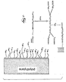
- FIG. 1 A schematic reaction process of a preferred embodiment of the present invention is shown in Figure 1 .
- polyethylene is treated with a hydrazine plasma to yield surface functionalized amino groups.
- the amino groups are reacted with DTPA in the presence of a coupling catalyst, e.g.,1,1'-cabonyldiimidazole, to effect an amide linkage between amino groups and DTPA.
- the surface amino-DTPA groups are then treated with gadolinium trichloride hexahydrate in an aqueous medium, coordinating the gadolinium (III) ion with the DTPA.
- the MR-signal-emitting coatings are suitably made via a four-step process which is similar to the three-step process except that prior to step (ii), i.e., prior to reaction with the chelating agent, a linker agent or spacer molecule, e.g., a lactam, is bound to the surface functional groups, resulting in the coating is of formula (II).
- a linker agent or spacer molecule e.g., a lactam
- FIG. 2 An illustrative schematic reaction process using a lactam or cyclic amide is shown in Figure 2 .
- a polyethylene with an amino functionalized surface is reacted with a lactam.
- the amino groups and lactam molecules are coupled via an amide linkage.
- "m" in the designation of the amino-lactam linkage is suitably an integer greater than 1.
- the polyethylene-amino-lactam complex is then reacted with DTPA which forms a second amide linkage at the distal end of the lactam molecule.
- the last step in the process, coordinating the gadolinium (III) ion with the DTPA (not shown in Figure 2 ), is the same as shown in Figure 1 .
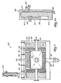
- Specific reaction conditions for forming a coating in accordance with the present invention, which utilizes surface functionalized amino groups include plasma treatment of a polymeric surface, e.g., a polyethylene surface, at 50 W power input in a hydrazine atmosphere within a plasma chamber, schematically represented in Figure 3 , for 5-6 min. under 13 Pa to 106 Pa (100 mT-800 mT).
- an exemplary plasma chamber designated generally by reference numeral 20, includes a cylindrical stainless steel reaction chamber 22 suitably having a 20 cm diameter, a lower electrode 24, which is grounded, and an upper electrode 26, both suitably constructed of stainless steel. Electrodes 24 and 26 are suitably 0.8 cm thick. Upper electrode 26 is connected to an RF-power supply (not shown). Both electrodes are removable which facilitates post-plasma cleaning operations. Lower electrode 24 also forms part of a vacuum line 28 through a supporting conical-shaped and circularly-perforated stainless steel tubing 30 that has a control valve 31. The evacuation of chamber 22 is performed uniformly through a narrow gap (3 mm) existing between lower electrode 24 and the bottom of chamber 22.
- Upper electrode 26 is directly connected to a threaded end of a vacuum-tight metal/ceramic feedthrough 32 which assures both the insulation of the RF-power line from the reactor and the dissipation of the RF-power to the electrodes.
- a space 34 between upper electrode 26 and the upper wall of chamber 22 is occupied by three removable 1 cm thick, 20 cm diameter Pyrex TM glass disks 36.
- Disks 36 insulate upper electrode 26 from the stainless steel top of the reactor 20 and allow the adjustment of the electrode gap.
- the reactor volume located outside the perimeter of the electrodes is occupied by two Pyrex TM glass cylinders 38 provided with four symmetrically located through-holes 40 for diagnostic purposes.
- This reactor configuration substantially eliminates the non-plasma zones of the gas environment and considerably reduces the radial diffusion of the plasma species, consequently leading to more uniform plasma exposure of the substrates (electrodes). As a result, uniform surface treatment and deposition processes (6-10% film thickness variation) can be achieved.
- the removable top part of the reactor 20 vacuum seals chamber 22 with the aid of a copper gasket and fastening bolts 42.
- This part of the reactor also accommodates a narrow circular gas-mixing chamber 44 provided with a shower-type 0.5 mm diameter orifice system, and a gas- and monomer supply connection 46.
- This gas supply configuration assures a uniform penetration and flow of gases and vapors through the reaction zone.
- the entire reactor 20 is thermostated by electric heaters attached to the outside surface of chamber 22 and embedded in an aluminum sheet 48 protecting a glass-wool blanket 50 to avoid extensive loss of thermal energy.
- a vapor supply assemblage 54 includes a plasma reservoir 56, valves 58, VCR connectors 60 and connecting stainless steel tubing 62. Assemblage 54 is embedded in two 1 cm thick copper jackets 64 20 provided with controlled electric heaters to process low volatility chemicals. Assemblage 54 is insulated using a glass-wool blanket coating. The thermostatic capabilities of reactor 20 are in the range of 25-250°C.
- the device to be coated is surface functionalized, it is then immersed in a solution of the chelating agent, e.g., DTPA, in, e.g., anhydrous pyridine, typically with a coupling catalyst, e.g., 1,1'-carbonyldiimidazole, for a time sufficient for the chelate to react with the amine groups, e.g., 20 hours.
- a solution of the chelating agent e.g., DTPA
- a coupling catalyst e.g., 1,1'-carbonyldiimidazole
- the chelate-treated surface is then soaked in an aqueous solution of GdCl 3 .6H 2 O, for a time sufficient for the paramagnetic ion to react with the chelate, e.g., 12 hours.
- the surface is then washed with water to remove any uncoordinated, physisorbed Gd(III) ion.
- each step has been verified to confirm that the bonding, in fact, occurs.
- x-ray photoelectron spectroscopy XPS
- a XPS spectrum of the polyethylene surface was taken prior to and after plasma treatment.
- the XPS spectrum of polyethylene before the treatment showed no nitrogen peak. After treatment, the nitrogen peak was 5.2% relative to carbon and oxygen peaks of 63.2% and 31.6%, respectively.
- step (i) the surface was reacted with p-trifluorobenzaldehyde or p-fluorophenone propionic acid and rinsed with a solvent (tetrahydrofuran).
- a solvent tetrahydrofuran
- This reactant chosen because of good sensitivity of fluorine atoms to XPS, produces many photoelectrons upon x-ray excitation.
- the result of the XPS experiment showed a significant fluorine signal.
- the peaks for fluorine, nitrogen, carbon and oxygen were: 3.2%, 1.5%, 75.7% and 19.6%, respectively. This demonstrated that the amino groups were accessible and capable of chemical reaction.
- the coatings in accordance with the present invention are advantageously applied to catheters and because a catheter surface is cylindrical, it is noted that to coat commercial catheters, the plasma reaction must be carried out by rotating the catheter axis normal to the plasma sheath propagation direction. Such rotational devices are known and can be readily used in the plasma reactor depicted in Figure 3 . To verify that surface amination occurs for such surfaces, atomic force microscopy (AFM) is used to study the surface morphology because XPS requires a well-defined planar surface relative to the incident X-ray.
- the coating densities e.g., nmol Gd 3+ /m 2
- optimal coating densities can be determined.
- metallic surfaces can be treated with the coatings in accordance with the present invention.
- Metallic surfaces e.g., guide-wires
- the magnetic resonance imageability of medical devices is enhanced or improved by encapsulating the medical device, or paramagnetic-metal-ion/chelate complexes linked thereto, with a hydrogel.
- catheters and other medical devices may be at least partially made or coated with a variety of polymers.
- the polymer surfaces of the existing medical devices are functionalized by plasma treatment or by melt coating with a hydrophilic polymer as discussed above or precoating with a hydrophilic polymer containing primary amine groups.
- a chelating agent may be covalently bonded to the functionalized polymer surface.
- any of the paramagnetic-metal ions discussed above can be complexed to the chelate.
- the necessary contrast for MRI is the result of interactions of protons in body fluid (e.g., blood) or bound within the encapsulating hydrogel with the highly magnetic ion, and the resulting shortening of T 1 relaxation time of the proton.
- body fluid e.g., blood
- the MR-imageability of the medical device is enhanced and improved. In other words, if the movement of these complexes is restricted, the MR-imageability of the polymer to which the complex is attached is greatly improved.
- one way by which to reduce the mobility of the complex for imaging is to encapsulate the medical device, and more particularly, the complex in a hydrogel.
- the hydrogel reduces the mobility of the paramagnetic-metal-ion/chelate complexes without significantly affecting the rate of water molecule exchange on the complexes, thereby enhancing the magnetic-resonance imageability of the medical devices.
- the reason for MR imageability for free paramagnetic-metal-ion/chelate complexes without being bonded to polymer surface comes about because of a much greater concentration of the complex in solution compared with that bound to the surface.
- hydrogels include, but are not limited to, at least one of collagen, gelatin, hyaluronate, fibrin, alginate, agarose, chitosan, poly(acrylic acid), poly(acrylamide), poly(2-hydroxyethyl methacrylate), poly(N-isopropylacrylamide), poly(ethylene glycol)/poly(ethylene oxide), poly(ethylene oxide)-block-poly(lactic acid), poly(vinyl alcohol), polyphosphazenes, polypeptides and combinations thereof.
- Any hydrogel or similar substance which reduces the mobility of the paramagnetic-metal-ion/chelate complex can also be used, such as physical hydrogels that can be chill-set without chemical cross-linking.
- hydrophilic polymers can be used, e.g., poly(acrylic acid), poly(vinyl alcohol), polyacrylamide, having a small fraction of functional groups that can be linked to residual amino groups are suitable for use with the invention.
- the MR-imageability of other MR-imageable devices made by methods other than those described herein may also be improved by coating other devices with the hydrogels described above.
- the devices can be encapsulated using a variety of known encapsulating techniques in the art. For example, a gel may be melted into a solution, and then the device dipped into the solution and then removed. More particularly, the gel may be dissolved in distilled water and heated. Subsequently, the solution coating the device is allowed to dry and physically self assemble to small crystallites that may adsorb to the polymer surface of the medical device and also play the role of cross-links. Such a phenomenon is commonly referred to as "chill-set" since it arises from thermal behavior of gelling systems.
- the gel may also be painted onto the medical device.
- the medical device may be encapsulated by polymerization of a hydrophilic monomer with a small fraction of cross-linker that participates in the polymerization process.
- a medical device may be immersed in a solution of acrylamide monomer with bisacrylamide as the cross-linker and a photo-initiator, and the polymerization is effected with ultra-violet (UV) irradiation to initiate the polymerization in a cylindrical optical cell.
- UV ultra-violet
- the medical device may be dipped into a gelatin solution in a suitable concentration (e.g., 5%), and mixed with a cross-linker such as glutaraldehyde.
- a cross-linker such as glutaraldehyde.
- cross-linker is meant to refer to any multi-functional chemical moiety which can connect two or a greater number of polymer chains to produce a polymeric network.
- suitable cross-linkers include, but are in no way limited to, BVSM (bis-vinylsulfonemethane) and BVSME (bis-vinylsulfonemethane ether). Any substance that is capable of cross-linking with the hydrogels listed above is also suitable for use with the invention.
- encapsulation is repeated until the desired thickness of the gel is obtained.
- the thickness of the encapsulated-hydrogel layer may be about 10 to about 60 microns, although it may be less and it may be more.
- the surface may be "primed” and then subsequently “painted” with a series of "coats” of gel until the desired thickness of the gel layer is obtained.
- the gel concentration is adjusted to bring about the desired thickness in a single coating process.
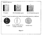
- three samples were prepared and tested as set forth and fully described in Example 10 below.
- FIG. 13 is a schematic representation of one example of the second embodiment of the invention, wherein a polyethylene rod, surface coated with amine-linked polymers, is chemically linked with DTPA, which is coordinated with Gd(III).
- the rod, polymer, DTPA and Gd(III) are encapsulated with a soluble gelatin, which is cross-linked with glutaraldehyde to form a hydrogel overcoat.
- Figure 14 shows the chemical details for the example schematically represented in Figure 13 .
- the second embodiment may be summarized as a coating for improving the magnetic-resonance imageability of a medical device comprising a complex of formula (III).
- the method includes encapsulating at least a portion of the device having at least one of the paramagnetic-metal-ion/chelate complexes covalently linked thereto with a hydrogel.
- the complex of formula (III) follows: (P - X- L - M n+ ) gel (III), wherein P is a base polymer substrate from which the device is made or with which the device is coated; X is a surface functional group; L is a chelate; M is a paramagnetic ion; n is an integer that is 2 or greater; and subscript "gel” stands for a hydrogel encapsulate.
- a polymer having functional groups is chemically linked with one or more of the chelates described above. More particularly, the polymer having a functional group (e.g. an amino or a carboxyl group) is chemically linked to the chelate via the functional group.
- a suitable polymer having functional groups is, but should not be limited to, poly(N[3-aminopropyl]methacrylamide), which has the following repeating unit structure:
- the third embodiment alleviates the need for a precoated polymer material on the medical device, or a medical device made from a polymer material.
- the third embodiment alleviates the need to link the paramagnetic-metal-ion/chelate complex to the surface of the medical device, when the medical device is made from or coated with a polymer.
- the polymer having functional groups preferably poly(N[3-aminopropyl] methacrylamide)
- the polymer having functional groups preferably poly(N[3-aminopropyl] methacrylamide)
- the polymer having functional groups preferably poly(N[3-aminopropyl] methacrylamide)
- the polymer and complex are coordinated separately, and then added to a hydrogel.
- the chelate may be coordinated with the paramagnetic-metal ion (e.g. Gd(III)), and then mixed with soluble gelatin and used to coat a bare (i.e. uncoated) polyethylene rod. Subsequently, the gelatin is chill-set and then the binary matrix of gelatin and polymer may be cross-linked with a cross-linker such as glutaraldehyde.
- the polymer used in connection with this embodiment may be a poly(N[3-aminopropyl] methacrylamide), the chelate may be DTPA and the paramagnetic-metal ion may be Gd(III).
- the hydrogel may be gelatin and the cross-linker may be glutaraldehyde.
- the surface of the medical device may be polyethylene.
- any of the polymers, chelates, paramagnetic-metal ions, hydrogels and cross-linkers discussed above are also suitable for use with this embodiment of the invention.
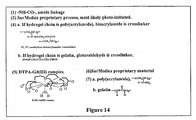
- FIG 16 is a schematic representation of one example of the third embodiment of the invention, wherein a polymer is chemically linked with DTPA, coordinated with Gd(III) and mixed with soluble gelatin. The resulting mixture is applied to a bare (i.e. uncoated) polyethylene surface and cross-linked with glutaraldehyde to form a hydrogel overcoat.
- Figure 17 shows the chemical details for the example schematically represented in Figure 16 .
- the third embodiment may be summarized as a coating for visualizing medical devices in magnetic resonance imaging comprising a complex of formula (IV).
- the method includes encapsulating at least a portion of the medical device with a hydrogel, wherein at least one of the paramagnetic-metal-ion/chelate complexes covalently linked to a polymer is dispersed in the hydrogel.
- the complex of formula (IV) follows: (S...P'-X- L - M n+ ) gel (IV) wherein S is a medical device substrate not having functional groups on its surface; P' is a polymer with functional groups X, the polymer not being linked to the surface of the medical device; L is a chelate; M is a paramagnetic ion; n is an integer that is 2 or greater; and subscript "gel” stands for a hydrogel encapsulate.
- a hydrogel having functional groups can be used instead of a primary polymer.
- gelatin may be used instead of the polymers discussed above.
- the gelatin or hydrogel rather than the polymer may be covalently linked with a chelate.
- the gelatin e.g., may be covalently linked to a chelate such as DTPA through the lysine groups of gelatin.
- hydrogels that are modified to have amine groups in the pendant chains can be used instead of the polymer, and can be linked to chelates using amine groups.
- the chelate is coordinated with a paramagnetic-metal ion such as Gd(III) as described above with respect to the other embodiments to form a paramagnetic-metal ion/chelate complex, and then mixed with a soluble hydrogel such as gelatin.
- the soluble hydrogel may be the same or may be different from the hydrogel to which the paramagnetic-metal ion/chelate complex is linked.
- the resulting mixture is used to coat a substrate or, e.g., a bare polyethylene rod. More particularly, the mixture is used to coat a medical device using the coating techniques described above with respect to the second embodiment. The coated substrate or medical device may then be chill-set.
- the hydrogel matrix or, for example, the gelatin-gelatin matrix may then be cross-linked with a cross-linker such as glutaraldehyde.
- a cross-linker such as glutaraldehyde.
- the cross-linking results in a hydrogel overcoat, and a substance which is MR-imageable.
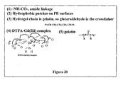
- FIG 19 is a schematic representation of one example of the fourth embodiment of the invention, wherein gelatin is chemically linked with DTPA, which is coordinated with Gd(III) and mixed with free soluble gelatin without any DTPA linked.
- the resulting mixture of gelatin and DTPA[Gd(III)] complex coats a bare polyethylene surface, and is then cross-linked with glutaraldehyde to form a hydrogel coat with DTPA[Gd(III)] dispersed therein.
- Figure 20 shows the chemical details for the example schematically represented in Figure 19 .
- the fourth embodiment can be summarized as a coating for visualizing medical devices in magnetic resonance imaging comprising a complex of formula (V).
- the method includes encapsulating at least a portion of the medical device with a hydrogel, wherein the hydrogel is covalently linked with at least one of the paramagnetic-metal-ion/chelate complexes.
- the complex of formula (V) follows: (S...G-X-L-M n+ ) gel (V) wherein S is a medical device substrate which is made of any material and does not having any functional groups on its surface; G is a polymer with functional groups X that can also form a hydrogel encapsulate; L is a chelate; M is a paramagnetic ion; n is an integer that is 2 or greater; and subscript "gel” stands for a hydrogel encapsulate.
- Polyethylene sheets were coated in the three-step process described herein.
- a polyethylene sheet (4.5 in diameter and 1 mil thick) was placed in a capacitively coupled, 50 kHz, stainless steel plasma reactor (as shown schematically in Figures 3 and 3A ) and hydrazine plasma treatment of the polyethylene film was performed.
- the substrate film was placed on the lower electrode.
- the base pressure was established in the reactor.
- the hydrazine pressure was slowly raised by opening the valve to the liquid hydrazine reservoir.
- Surface atomic composition of untreated and plasma-treated surfaces were evaluated using XPS (Perkin-Elmer Phi-5400; 300 W power; Mg source; 15 kV; 45° takeoff angle).
- DTPA Coating In a 25 mL dry flask, 21.5 mg of DTPA was added to 8 mL of anhydrous pyridine. In a small vessel, 8.9 mg of 1,1'-carbonyldiimidazole (CDI), as a coupling catalyst, was dissolved in 2 mL of anhydrous pyridine. The CDI solution was slowly added into the reaction flask while stirring, and the mixture was stirred at room temperature for 2 hours. The solution was then poured into a dry Petri dish, and the hydrazine-plasma treated polyethylene film was immersed in the solution. The Petri dish was sealed in a desiccator after being purged with dry argon for 10 min. After reaction for 20 hours, the polyethylene film was carefully washed in sequence with pyridine, chloroform, methanol and water. The surface was checked with XPS, and the results showed the presence of carboxyl groups, which demonstrate the presence of DTPA.
- CDI 1,1'-carbonyld
- BE binding energy
- Coated polyethylene sheets were prepared according to the method of Example 1, except that after surface amination, the polyethylene sheet was reacted with a lactam, and the sheet washed before proceeding to the chelation step. The surface of the film was checked for amine groups using XPS.
- Example 3 Imaging of coated polyethylene and polypropylene sheets
- MR signal enhancement was assessed by imaging coated sheets of polyethylene and polypropylene, prepared as described in Example 1, with gradient-recalled echo (GRE) and spin-echo (SE) techniques on a clinical 1.5 T scanner.
- GRE gradient-recalled echo
- SE spin-echo
- the sheets were held stationary in a beaker filled with a tissue-mimic, fat-free food-grade yogurt, and the contrast-enhancement of the coating was calculated by normalizing the signal near the sheet by the yogurt signal.
- the T 1 -weighed GRE and SE MR images showed signal enhancement near the coated polymer sheet.
- the T 1 estimates near the coated surface and in the yogurt were 0.4 s and 1.1 s, respectively. No enhancement was observed near control sheets.
- the MR images acquired are shown in Figure 4 .
- a DTPA[Gd(III)] filled single lumen catheter 3-6 French (1-2 mm) was imaged in an acrylic phantom using a conventional MR Scanner (1.5T Signa, General Electric Medical Systems) while it was moved manually by discrete intervals over a predetermined distance in either the readout direction or the phase encoding direction.
- the phantom consisted of a block of acrylic into which a series of channels had been drilled.
- the setup permitted determination of the tip position of the catheter with an accuracy of ⁇ 1 mm (root-mean-square). Snapshots of the catheter are shown in Figure 5 .
- Example 5 In vivo testing of DTPA[Gd(III)] filled catheter visualization
- Example 6 In vivo catheter MR visualization
- a catheter coated with a coating in accordance with the present invention/guide-wire combination is initially positioned in the femoral artery. Under MR guidance, the catheter is moved first to the aorta, then to the carotid artery, then to the circle of Willis, and on to the middle cerebral artery. The catheter movement is clearly seen in the vessels. The length of time to perform this procedure and the smallest vessel successfully negotiated is recorded.
- Example 7 Paramagnetic ion safety testing
- a gadolinium leaching test is performed to ascertain the stability of the DTPA[Gd(III)] complex.
- Polyethylene sheets coated with a coating in accordance with the present invention are subjected to simulated blood plasma buffers and blood plasma itself. NMR scans are taken and distinguish between chelated Gd 3+ and free Gd 3+ . The results indicate that the Gd 3+ complex is stable under simulated blood conditions.
- a biocompatibility test formulated as non-specific binding of serum proteins, is carried out on polymeric surfaces coated in accordance with the present invention using an adsorption method of serum albumin labeled with fluorescent dyes. If the albumin is irreversibly adsorbed as detected by fluorescence of coated catheter surfaces, the coat is adjudged to be not biocompatible.
- a clinical 1.5 T scanner (Signa, General Electric Medical Systems) is used to determine the optimal range of coating densities (in mmol Gd 3+ /m 2 ) for producing appreciable signal enhancement on a series of silicon wafers coated with a polyethylene-Gd-containing coating in accordance with the present invention.
- the wafers are placed in a water bath and scanned cross-sectionally using a moderately high-resolution fast gradient-recalled echo (FGRE) sequence with TR ⁇ 7.5 ms/TE ⁇ 1.5 ms, 256 X 256 acquisition matrix and a 16 cm X 16 cm field-of-view (FOV).
- the flip angle is varied from 10° to 90° in 10° increments for each coating density.
- a region of interest (ROI) is placed in the water adjacent to the wafer and the absolute signal is calculated.
- the vials contain various concentrations of DTPA[Gd(III)], ranging from 0 mmol/mL to 0.5 mmol/mL. This range of concentrations corresponds to a range of T 1 relaxation times (from ⁇ 10 ms to 1000 ms) and a range of T 2 relaxation times.
- the signals in each vial are also measured and used to normalize the signals obtained near the wafers. Normalization corrections for effects due to different prescan settings between acquisitions and variable image scaling are applied by the scanner.
- a range of concentrations in the vials facilitates piece-wise normalization. An optimal range of coating densities is determined.
- Example 10 Comparison testing of MR-imageability of three differently coated samples.
- PE rods were used in a variety of tests in order to mimic the surface of a catheter or medical device.
- the PE rods (2mm diameter) were functionalized or precoated with a hydrophilic polymer containing primary amine groups. Through amide linkage, diethylenetrimaminepentaacetic acid (DTPA) was covalently attached to the rods. Subsequently, Gd(III) was complexed to the DTPA.
- DTPA diethylenetrimaminepentaacetic acid
- the necessary contrast for MRI is the result of interactions of proton of water in body fluid (e.g., blood) with the highly magnetic Gd(III) ion, and the resulting shortening of T 1 relaxation time of the water protons.
- body fluid e.g., blood
- Gd(III) ion highly magnetic Gd(III) ion
- T 1 relaxation time of the water protons To reduce the mobility of the DTPA[Gd(III)] complex for imaging in accordance with the present invention agarose gel was used to encapsulate the entire assembly. Such a rod was used as Sample 2 in the testing as further described below.
- Sample 1 was a blank sample, i.e. a PE rod encapsulated with agarose gel but having no DTPA[Gd(III)] complexed to the rod;
- Sample 3 was a PE rod encapsulated with agarose gel containing a DTPA[Gd(III)] complex, but the complex was not covalently linked to the PE rods.
- MRI tests were carried out in three media: 1) a fat-free food-grade yogurt (a tissue mimic); 2) a physiological saline (a serum mimic); and 3) human blood.
- sample 1 the blank sample having no DTPA[Gd(III)] complex, but encapsulated in agarose (Sample 1); the chemically-bound or covalently linked DTPA[Gd(III)] complex encapsulated in agarose (Sample 2); and the unbound DPTA[Gd(III)] encapsulated in agarose (Sample 3).
- Sample 1 the blank, gave no detectable MRI signal.
- Sample 2 gave clearly detectable signals up to ten hours.
- Sample 3 lost signal intensity with time, thereby indicating a slow leaching of DTPA[Gd(III)] complex from the agarose gel matrix because it was not covalently bound to the polymer of the medical device. Given the observed MR images of Samples 2 and 3, the agarose encapsulation is adjudged to be optimal.
- Sample 1 was prepared by coating blank PE rods with agarose gel.
- the PE rods for Sample 1 and all samples were obtained from SurModics, Inc. located at 9924 West 74 th Street, Eden Prairie, Minnesota 55344-3523.
- Agarose (type VI-A) was purchased from Sigma located in St. Louis, Missouri, with gel point (1.5% gel) at 41.0° ⁇ 1.5°C, gel strength (1.5%) expressed in units of elastic modulus larger than 1200g/cm 2 , and melting temperature 95.0° ⁇ 1.5°C.
- 0.60 g agarose was dissolved in 40 mL distilled water in a flask maintained at 100°C for 5 min. The solution was kept in a water bath at 50-60°C.
- the PE rods were then dipped into the agarose solution. After removing the rods from the solution, the rods were cooled to room temperature in order to allow a gel-coating to form on the rod surface. The same procedure was repeated to overcoat additional layers of agarose, and it was repeated for 5 times for each rod. Thus, all rods were expected to have about the same gel-coating thickness.
- PE rods with an amine-containing-polymer coating were provided by SurModics, Inc.
- SurModics, Inc. functionalizes the PE surface of the rods by a photochemical attachment of poly(2-aminoethyl methacrylate) in order to provide functional groups, more specifically, amine groups, on the functionalized surface of the rods.
- the PE rods in the example were meant to mimic the surface of existing medical devices made from a wide variety of polymers.
- Diethylenetriaminepentaacetic acid (DTPA), gadolinium trichloride hexahydrate, GdCl 3 ⁇ 6H 2 O (99.9%), dicyclohexylcarbodiimide (DCC), and 4-(dimethylamino)-pyridine (DMAP) were all purchased from Aldrich located at Milwaukee, Wisconsin, and used without further purification.
- Agarose (type VI-A) was purchased from Sigma located at St. Louis, Missouri, with gel point (1.5% gel) at 41.0° ⁇ 1.5°C, gel strength (1.5%) larger than 1200g/cm 2 , and melting temperature 95.0° ⁇ 1.5°C.
- Human blood used in the MRI experiments were obtained from the University of Wisconsin Clinical Science Center Blood Bank located in Madison, Wisconsin.
- the MRI-signal-emitting coatings were prepared on the PE rods, i.e. the pre-existing rods were made MR-imageable, by the chemical synthesis depicted in Figure 8 .
- the individual steps of the chemical synthesis are explained in detail below.
- DTPA i.e. chelate
- 0.165 g DTPA (0.42 mmol) was dissolved in 30 mL of 1:1 (by volume) mixture of pyridine and DMSO in a flask and stirred at 80°C for 30 min.
- 5-cm long PE rods having the amine-containing-polymer coating were immersed in the solution.
- 0.090 g DCC (0.43 mmol) and 0.050 g DMAP (0.41 mmol) solution in pyridine (4mL) was slowly added to the solution while stirring.
- the reaction mixture was kept in an oil bath at 60°C for 24 hours while stirring.
- the PE rods were removed from the solution and washed three times - first with DMSO and then with methanol, respectively.
- Sample 3 was prepared by coating PE rods with agarose gel and a DTPA[Gd(III)] mixture.
- 0.45 g agarose (also obtained from Sigma) was dissolved in 30 mL distilled water in a flask maintained at 100°C for 5 min. Then, 3 mL of 0.4% solution of DTPA[Gd(III)] was added to the agarose solution. The solution was kept in a water bath at 50-60°C. The rods were dipped into the agarose solution, and then were removed. The adsorbed solution on the rod was cooled to room temperature to allow a gel-coating to form. The same procedure was repeated to coat additional layers of agarose, and it was repeated for 5 times altogether for each rod.
- Sample 3 differed from Sample 2 in that the DTPA[Gd(III)] complex was not covalently bonded to the PE rod using the methods of the present invention. Instead, a DTPA[Gd(III)] mixture was merely added to the agarose solution, resulting in dispersion of the same in the gel upon encapsulation in 5-layer coating.
- XPS x-ray photoelectron spectroscopy
- MR magnetic resonance
- MR evaluation of the signal-emitting rods was performed on a clinical 1.5T scanner.
- the PE rods were each imaged in the following medium: 1) yogurt as a suitable tissue mimic; 2) saline as an electrolyte mimic of blood serum; and 3) and human blood.
- Spin echo (SE) and RF spoiled gradient-recalled echo (SPGR) sequences were used to acquire images.
- the surface chemical composition of the rods was determined by the XPS technique.
- Table 2 below, lists the relative surface atomic composition of the untreated rods as provided by SurModics (Eden Prairie, MN).
- Table 3 shows the relative surface composition of the treated (DTPA[Gd(III)] linked) rods.
- the relative composition of oxygen increased from 10.8% to 25.9% as seen in Tables 2 and 3. This indicates that DTPA is indeed attached to the polymer surface.
- Gd(III) was complexed to the DTPA on the polymer surface, thus giving rise to the surface Gd composition of 3.2%.
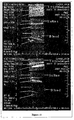
- Table 2 Surface compositions in % of 3 elements, C, N and O, of PE rods coated with the NH 2 -containing polymer (SurModics). Location C(1s) N(1s) O(1s) 1 80.7 8.6 10.7 2 80.2 8.3 11.5 3 80.4 9.3 10.3 average 80.4 ( ⁇ 0.3) 8.7 ( ⁇ 0.5) 10.8 ( ⁇ 0.6) Table 3 Surface composition in % of 4 elements of the PE rods linked with DTPA[Gd(III)] Location C(1s) N(1s) O(1s) Gd(4d) 1 65.2 5.8 25.9 3.1 2 63.2 7.2 26.5 3.1 3 63.6 7.8 25.2 3.3 average 64.0 ( ⁇ 1.0) 6.9 ( ⁇ 1.0) 25.9 ( ⁇ 0.7) 3.2 ( ⁇ 0.1)
- the polymer rods linked with DTPA[Gd(III)] and encapsulated by agarose gel were imaged in yogurt, saline and human blood.
- the control rods i.e., the PE rods having no chemical treatment but having only the gel overcoat (Sample 1) as well as PE rods coated with the gel in which DTPA[Gd(III)] is dispersed but not covalently linked (Sample 3) were also imaged in yogurt, saline and blood using spin echo (SE) and RF spoiled gradient-recalled echo (SPGR) sequences.
- SE spin echo
- SPGR RF spoiled gradient-recalled echo
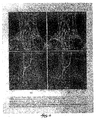
- the three kinds of samples and the MRI imaging set-up are illustrated in Figure 9 .
- Figure 10 shows the longitudinal MR image of each sample in each medium after 15+ minutes
- Figure 11 shows the longitudinal MR images after 60+ minutes
- Figure 12 shows the longitudinal MR images of each sample in each medium after 10+ hours.
- Sample 1 i.e. PE rods coated only with the gel and without DTPA[Gd(III)]
- Sample 2 i.e. PE rods covalently-linked with DTPA[Gd(III)] with overcoats of the gel
- Sample 2 i.e. PE rods covalently-linked with DTPA[Gd(III)] with overcoats of the gel
- Sample 3 is also visible in yogurt, saline, and blood; however, DTPA[Gd(III)] appears to leach and diffuse out of the gel overcoat with time because it is not covalently bonded to the polymer rod. For example, after 10 hours, sample 3 is not visible in saline or blood.
- DTPA Diethylenetriaminepentaacetic acid
- GdCl 3 ⁇ 6H 2 O 99.9%
- dicyclohexylcarbodiimide DCC
- 4-(dimethylamino)-pyridine DMAP
- dimethyl sulfoxide DMSO
- pyridine pyridine
- Gelatin type (IV) was provided by Eastman Kodak Company as a gift.
- Glutaraldehyde(25% solution) was purchased from Sigma, St. Louis, Missouri. These materials were used in Example 11, as well as Examples 12-13.
- DTPA 0.165 g DTPA (0.42 mmol) was dissolved in 30 mL of 2:1 (by volume) mixture of pyridine and DMSO in a flask and stirred at 80° C for 30 min. Then, a 40-cm long polyethylene (PE) rod (diameter 2mm) with the amine containing polymer precoating were immersed in the solution.
- the PE rods with an amine-containing-polymer coating were provided by SurModics, Inc.
- SurModics, Inc. functionalizes the PE surface of the rods by a photochemical attachment of poly(2-aminoethyl methacrylate) in order to provide functional groups, more specifically, amino groups, on the functionalized surface of the rods.
- the PE rods were meant to mimic the surface of existing medical devices made from a wide variety of polymers.
- a pyridine solution (4mL) containing amidation catalysts, 0.090 g DCC (0.43 mmol) and 0.050 g DMAP (0.41mmol)
- the reaction mixture was kept in an oil bath at 60° C for 24 hours with stirring to complete the bonding of DTPA to the amine groups on the precoated polymer via amide linkage.
- the PE rods were removed from the solution and washed three times first with DMSO and then with methanol.
- a sample of gelatin weighing 20 g was dissolved in 100 mL of distilled water at 60° C for 1 hour with stirring. The solution was transferred to a long glass tube with a jacket and kept the water bath through the jacket at 35°C.
- DTPA[Gd(III)] attached PE rods (40-cm long) were then dipped into the solution, and the rods upon removing from the solution were cooled to room temperature in order to allow a gel-coating to chill-set, i.e., to form as a hydrogel coating on the rod surface.
- the final dry thickness of gel-coating was around 30 ⁇ m. The same procedure may be repeated to overcoat additional layers of the gel. When it was repeated twice, the final dry thickness of gel-coating was around 60 ⁇ m.
- the coated PE rods was soaked in 0.5% glutaraldehyde 300 mL for 2 hours to cross-link the gelatin coating. Then the rods were washed by distilled water and further soaked in distilled water for one hour to remove any residual free glutaraldehyde and GdCl 3 . Finally the gel-coated rods were dried in air.
- the surface chemical composition of the rods was determined by the XPS technique. The results are similar to that in Example 10. After the chemical treatment, DTPA is indeed attached to the polymer surface and Gd(III) was complexed to the DTPA on the polymer surface with the surface Gd composition around 3%.
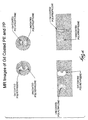
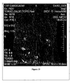
- Figure 15 is a 3D maximum-intensity-projection (MIP) MR image of the PE rods 25 minutes after it was inserted into the canine aorta.
- MIP maximum-intensity-projection
- Example 12 Again, the same materials as set forth in Example 11 were used in conjunction with Example 12.
- the guide wire used in this example is a commercial product from Meditech, Inc (480 pleasant street/P.O. Box 7407, Watertown, MA 02272) with the diameter of 0.038 in. and length of 150 cm.
- DTPA Diethylenetriaminepentaacetic acid
- DTPA 0.79 g of DTPA (2 mmol) was dissolved in 20 mL DMSO at 80° C for 30 minutes, and then the solution was cooled to room temperature. 0.14 g poly(N-[3-aminopropyl] methylacrylamide) having one mmol of repeating unit and separately synthesized in-house was dissolved with 0.206 g DCC (1mmol) 20 mL of DMSO. The solution was slowly added to the DTPA solution dropwise with stirring. When all of the polymer and DCC solution was added, the final mixture was stirred for 8 hours at room temperature and then filtered. 200 mL of diethyl ether was added to the filtered solution to precipitate the product, a mixture of free DTPA and DTPA linked polymer. The solid product was collected by filtration and dried.
- the coated guide wire was soaked in 0.5% glutaraldehyde 300 ml for 2 hours to cross-link the gelatin and the primary polymer. Then, the rods were first washed with distilled water and soaked further in distilled water for 2 hours to remove all soluble and diffusible materials such as free DTPA and glutaraldehyde.
- the wire was soaked in a solution of 1.70g GdCl 3 .6H 2 O dissolved in 300 mL of distilled water for 8 to 10 hours. Then, the wire was washed with distilled water and further soaked for 8 to 10 hours to remove free GdCl 3 . Finally the gel-coated wire was dried in air.
- the guide-wire with a functional gelatin coating in which DTPA[Gd(III)] linked polymer was dispersed and cross-linked with gelatin, was imaged in a canine aorta using 2D and 3D RF spoiled gradient-recalled echo (SPGR) sequences.
- Figure 18 is the 3D maximum-intensity-projection (MIP) MR image of the guide wire 10 minutes after it was inserted into the canine aorta.
- MIP maximum-intensity-projection
- Example 11-12 were used in conjunction with Example 13.
- the catheter used in this example is a commercial product from Target Therapeutics, Inc. (San Jose, California 95134) having a length of 120 cm and diameter of 4.0F.
- the coated guide wire and catheter were soaked in 0.5% glutaraldehyde 300 ml for 2 hours in order to cross-link the gelatin coating. Then, guide wire and catheter were first washed with distilled water and soaked further for 2 hours to remove all soluble and diffusible materials such as free DTPA and glutaraldehyde.
- the rods were soaked in a solution of 1.7 g GdCl 3 ⁇ 6H 2 O dissolved in 300 ml of distilled water for 8 to 10 hours. Then the guide-wire and catheter were washed with distilled water and further soaked for 8 to 10 hours to remove the free GdCl 3 . Finally the gel-coated guide-wire and catheter were dried in air.
- FIG. 20 is the 3D MIP MR image of the guide wire 30 minutes after it was inserted into the canine aorta.
- the coated guide-wire is visible in canine aorta as shown in Figure 21 .
- the signal of the coated guide-wire improved with time.
- the catheter with a functional gelatin coating in which DTPA[Gd(III)] linked gelatin was dispersed, was imaged in canine aorta, the results of which are shown in Figure 22 .
- the thickness of gelatin coating is 30 ⁇ m.
- the diameter of the coated catheter is 4.0F and the length of coated part is around 45 cm.
- Figure 22 is the 3D MIP MR image of the catheter 20 minutes after it was inserted into the canine aorta.
- the coated catheter is visible and bright in canine aorta as shown in Figure 22 .
- the MR signal intensity of coated catheter improved with time.
- the present invention provides a method of visualizing pre-existing medical devices under MR guidance utilizing a coating, which is a polymeric-paramagnetic ion complex, on the medical devices.
- a coating which is a polymeric-paramagnetic ion complex
- the methods practiced in accordance with the present invention provide various protocol for applying and synthesizing a variety of coatings.
Landscapes
- Health & Medical Sciences (AREA)
- General Health & Medical Sciences (AREA)
- Veterinary Medicine (AREA)
- Epidemiology (AREA)
- Life Sciences & Earth Sciences (AREA)
- Animal Behavior & Ethology (AREA)
- Public Health (AREA)
- Physics & Mathematics (AREA)
- Radiology & Medical Imaging (AREA)
- Nuclear Medicine, Radiotherapy & Molecular Imaging (AREA)
- Surgery (AREA)
- Optics & Photonics (AREA)
- Vascular Medicine (AREA)
- Heart & Thoracic Surgery (AREA)
- Medicinal Chemistry (AREA)
- Chemical & Material Sciences (AREA)
- Pathology (AREA)
- Condensed Matter Physics & Semiconductors (AREA)
- General Physics & Mathematics (AREA)
- Materials For Medical Uses (AREA)
- Magnetic Resonance Imaging Apparatus (AREA)
- Medicines Containing Antibodies Or Antigens For Use As Internal Diagnostic Agents (AREA)
Description
- This invention relates in general to coatings that emit magnetic resonance signals and in particular, to such coatings containing paramagnetic metal ions, and to a process for coating devices and implants with such coatings so that these devices are readily visualized in magnetic resonance images during diagnostic or therapeutic procedures done in conjunction with magnetic resonance imaging (MRI).
- Since its introduction, magnetic resonance (MR) has been used to a large extent solely for diagnostic applications. Recent advancements in magnetic resonance imaging now make it possible to replace many diagnostic examinations previously performed with x-ray imaging with MR techniques. For example, the accepted standard for diagnostic assessment of patients with vascular disease was, until quite recently, x-ray angiography. Today, MR angiographic techniques are increasingly being used for diagnostic evaluation of these patients. In some specific instances such as evaluation of patients suspected of having atheroscleroic disease of the carotid arteries, the quality of MR angiograms, particularly if they are done in conjunction with contrast-enhancement, reaches the diagnostic standards previously set by x-ray angiography.
- More recently, advances in MR hardware and imaging sequences have begun to permit the use of MR for monitoring and control of certain therapeutic procedures. That is, certain therapeutic procedures or therapies are performed using MR imaging for monitoring and control. In such instances, the instruments, devices or agents used for the procedure and/or implanted during the procedure are visualized using MR rather than with x-ray fluoroscopy or angiography. The use of MR in this manner of image-guided therapy is often referred to as interventional magnetic resonance (interventional MR). These early applications have included monitoring ultrasound and laser ablations of tumors, guiding the placement of biopsy needles, and monitoring the operative removal of tumors.
- Of particular interest is the potential of using interventional MR for the monitoring and control of endovascular therapy. Endovascular therapy refers to a general class of minimally-invasive interventional (or surgical) techniques which are used to treat a variety of diseases such as vascular disease and tumors. Unlike conventional open surgical techniques, endovascular therapies utilize the vascular system to access and treat the disease. For such a procedure, the vascular system is accessed by way of a peripheral artery or vein such as the common femoral vein or artery. Typically, a small incision is made in the groin and either the common femoral artery or vein is punctured. An access sheath is then inserted and through the sheath a catheter is introduced and advanced over a guide-wire to the area of interest. These maneuvers are monitored and controlled using x-ray fluoroscopy and angiography Once the catheter is properly situated, the guide-wire is removed from the catheter lumen, and either a therapeutic device (e.g., balloon, stent, coil) is inserted with the appropriate delivery device, or an agent (e.g., embolizing agent, anti-vasospasm agent) is injected through the catheter. In either instance, the catheter functions as a conduit and ensures the accurate and localized delivery of the therapeutic device or agent to the region of interest. After the treatment is completed, its delivery system is withdrawn, i.e., the catheter is withdrawn, the sheath removed and the incision closed. The duration of an average endovascular procedure is about 3 hours, although difficult cases may take more than 8 hours. Traditionally, such procedures have been performed under x-ray fluoroscopic guidance.
- Performing these procedures under MR-guidance provides a number of advantages. Safety issues are associated with the relatively large dosages of ionizing radiation required for x-ray fluoroscopy and angiographic guidance. While radiation risk to the patient is of somewhat less concern (since it is more than offset by the potential benefit of the procedure), exposure to the interventional staff can be a major problem. In addition, the adverse reactions associated with MR contrast agents is considerably less than that associated with the iodinated contrast agents used for x-ray guided procedures.
- Other advantages of MR-guided procedures include the ability to acquire three-dimensional images. In contrast, most x-ray angiography systems can only acquire a series of two-dimensional projection images. MR has clear advantages when multiple projections or volume reformatting are required in order to understand the treatment of complex three-dimensional vascular abnormalities, such as arterial-venous malformations (AVMs) and aneurysms. Furthermore, MR is sensitive to measurement of a variety of "functional" parameters including temperature, blood flow, tissue perfusion, diffusion, and brain activation. This additional diagnostic information, which, in principle, can be obtained before, during and immediately after therapy, cannot be acquired by x-ray fluoroscopy alone. It is likely that once suitable MR-based endovascular procedures have been developed, the next challenge will be to integrate this functional information with conventional anatomical imaging and device tracking.
- Currently, both "active" and "passive" approaches are being used for visualization and monitoring of the placement of devices and materials used for therapeutic procedures done using MR guidance. When active tracking is used, visualization is accomplished by incorporating one or more small radio-frequency (RF) coils into the device, e.g., a catheter.
- The position of the device is computed from MR signals generated by these coils and detected by MR imager. This information is superimposed on an anatomical "road map" image of the area in which the device is being used. The advantages of active tracking include excellent temporal and spatial resolution. However, active methods allow visualization of only a discrete point(s) on the device. Typically, only the tip of the device is "active", i.e., visualized. Although it is possible to incorporate multiple RF coils (4-6 on typical clinical MR systems) into a device, it is still impossible to determine position at more than a few discrete points along the device. While this may be acceptable for tracking rigid biopsy needles, this is a significant limitation for tracking flexible devices such as those used in endovascular therapy. Furthermore, intravascular heating due to RF-induced currents is a concern with active methods.
- The attachment of coils onto flexible catheter presents numerous challenges in maintaining the functionality of the catheter as these coils result in changes in the mechanical properties of the catheter onto which they are incorporated. Ladd et al. [Ladd et al., Proc. ISMRM (1997) 1937] have addressed some of the deficiencies of an active catheter by designing a RF coil that wraps about the catheter.
- This allows visualization of a considerable length of a catheter, but still does not address the problems of RF heating and the mechanical changes which degrade catheter performance.
- One technique for passive tracking is based on the fact that some devices do not emit a detectable MR signal and also cause no artifacts in the MR image. This results in such a device being seen as an area of signal loss or signal void in the MR images. By tracking or following the signal void, the position and motion of such a device can be determined. One advantage of passive tracking methods over active methods is that they do allow "visualization" of the entire length of a device. Since air, cortical bone and flowing blood are also seen in MR images as areas of signal voids, the use of signal void is generally not appropriate for tracking devices used in interventional MR. Another technique of passive tracking utilizes the fact that some materials cause a magnetic susceptibility artifact (either signal enhancement or signal loss) that causes a signal different from the tissue in which they are located. Some catheters braided with metal, some stents and some guide-wires are examples of such devices. One problem with the use of these techniques based on susceptibility artifacts is the fact that those used for localization of the device does not correspond precisely with the size of the device. This makes precise localization difficult.
- A number of published reports describe passive catheter visualization schemes based on signal voids or susceptibility-induced artifacts. A principal drawback of these passive techniques is that visualization is dependent on the orientation of the device with respect to the main magnetic field.
- Despite recognition and study of various aspects of the problems of visualization of medical devices in therapeutic, especially endovascular, procedures, the prior art has still not produced satisfactory and reliable techniques for visualization and tracking of the entire device in a procedure under MR guidance.
-
WO-A-9960920
P-X-L-Mn+
wherein P is a polymer, X is a surface functional group, L is a chelate, M is a paramagnetic ion an n is an integer that is 2 or greater. -
WO-A1-02/22186 - (a) contacting a surface of the device with a (i) binder polymer, and (ii) a hydrophilic polymer which is substantially more lubricious when wetted with an aqueous liquid than when dry; and
- (b) contacting the surface with an effective amount of a magnetic susceptible agent to cause the surface of the medical device to be detectable by magnetic resonance imaging.
-
WO-A1-01/81460 - The present invention provides a process for coating medical devices so that the devices are readily visualized, particularly, in T1 weighted magnetic resonance images. Because of the high signal caused by the coating, the entirety of the coated devices can be readily visualized during, e.g., an endovascular procedure.
- The foregoing, and other advantages of the present invention, are realized in a magnetic resonance (MR) signal-emitting coating which includes a paramagnetic metal ion-containing polymer complex and a method of visualizing medical devices in magnetic resonance imaging, which includes the step of coating the devices with the paramagnetic-ion containing polymer. Specifically, the present invention provides a coating for visualizing medical devices in magnetic resonance imaging, comprising a complex of formula (I):
P-X-L-Mn+ (I)
wherein P is a polymer, X is a surface functional group, L is a chelate, M is a paramagnetic ion and n is an integer that is 2 or greater. The polymer P may be a base polymer from which a medical device is made. - In another aspect, the invention is a coating for visualizing medical devices in magnetic resonance imaging, comprising a complex of formula (II):
P - X - J - L - Mn+ (II)
wherein P is a polymer, X is a surface functional group, L is a chelate, M is a paramagnetic ion, n is an integer that is 2 or greater and J is the linker or spacer molecule. The polymer P may be a base polymer from which a medical device is made. - In a further aspect, the invention is a magnetic resonance imaging system which includes a magnetic resonance device for generating a magnetic resonance image of a target object (as defined hereinafter) in an imaging region (as defined hereinafter) and an instrument for use with the target object in the imaging region. The instrument includes a body sized for use in the target object and a polymeric-paramagnetic ion complex coating in which the complex is represented by formula (I) through (V) as set forth below in the detailed description.
- In yet another aspect, the invention is a method for visualizing medical devices in magnetic resonance imaging which includes the steps of (a) coating the medical device with a polymeric-paramagnetic complex of formula (I) through (V) as set forth below in the detailed description; (b) positioning the device within a target object; and (c) imaging the target object and coated device.
- In a further aspect, the invention provides a method of making a medical device magnetic-resonance imageable. The method comprises providing a coating on the medical device in which a paramagnetic-metal ion/chelate complex is encapsulated by a first hydrogel. A chelate of the paramagnetic-metal-ion/chelate complex is linked to a functional group, and the functional group is an amino group or a carboxyl group. The paramagnetic-metal ion may, but need not be, designated as Mn+, wherein M is a lanthanide or a transition metal which is iron, manganese, chromium, cobalt or nickel, and n is an integer that is 2 or greater. In one embodiment, at least a portion of the medical device may be made from a solid-base polymer, and the method further comprises treating the solid-base polymer to yield the functional group thereon. Accordingly, the complex is covalently linked to the medical device. In another embodiment, the functional group may be a functional group of a polymer that is not covalently linked to the medical device. In a different embodiment, the functional group may be a functional group of a second hydrogel. The first and second hydrogels may be the same or different. A cross-linker may also be used to cross-link the first hydrogel with the solid-base polymer, the polymer not covalently linked to the medical device or the second hydrogel, depending upon the embodiment.
- In another aspect, the invention provides a medical device capable of being magnetic-resonance imaged. The device comprises a chelate linked to a functional group. The functional group may be an amino or a carboxyl group. The device also comprises a paramagnetic-metal ion that is coordinated with the chelate to form a paramagnetic-metal-ion/chelate complex. The device also comprises a first hydrogel that encapsulates the paramagnetic-metal-ion/chelate complex. The paramagnetic-metal ion may, but need not be, designated as Mn+, wherein M is a lanthanide or a transition metal which is iron, manganese, chromium, cobalt or nickel, and n is an integer that is 2 or greater. In one embodiment, at least a portion of the medical device may be made from a solid-base polymer, and the functional group is a functional group on the solid-base polymer. Accordingly, the complex is covalently linked to the medical device. In another embodiment, the functional group may be a functional group of a polymer that is not covalently linked to the medical device. In a different embodiment, the functional group may be a functional group of a second hydrogel. The first and second hydrogels may be the same or different. A cross-linker may also be used to cross-link the first hydrogel with the solid-base polymer, the polymer not covalently linked to the medical device or the second hydrogel, depending upon the embodiment.
- In yet another aspect, the invention provides a method of reducing the mobility of paramagnetic metal ion/chelate complexes covalently linked to a solid polymer substrate of a medical device. This method includes providing a medical device having paramagnetic metal ion/chelate complexes covalently linked to the solid polymer substrate of the medical device. The method also includes encapsulating at least a portion of the medical device having at least one of the paramagnetic metal ion/chelate complexes covalently linked thereto with a hydrogel. The hydrogel reduces the mobility of at least one of the paramagnetic metal ion/chelate complexes, and thereby enhances the magnetic resonance imageability of the medical device.
- Other advantages and a fuller appreciation of the specific attributes of this invention will be gained upon an examination of the following drawings, detailed description of preferred embodiments, and appended claims. It is expressly understood that the drawings are for the purpose of illustration and description only, and are not intended as a definition of the limits of the invention.
- The preferred exemplary embodiment of the present invention will hereinafter be described in conjunction with the appended drawing wherein like designations refer to like elements throughout and in which:
-
Figure 1 is a schematic representation of the three-step coating method in accordance with the present invention; -
Figure 2 is a schematic representation of the four-step coating method using a linker agent; -
Figures 3 and 3A are schematic representations of a capacitively coupled RF plasma reactor for use in the method of the present invention,Figure 3A being an enlarged view of the vapor supply assemblage of the plasma reactor ofFigure 3 ; -
Figure 4 is several MR images of coated devices in accordance with the present invention; -
Figure 5 is temporal MR snapshots of a Gd-DTPA-filled catheter, -
Figure 6 is temporal MR snapshots of a Gd-DTPA-filled catheter moving in the common carotid of a canine; -
Figure 7 is temporal MR snapshots of a Gd-DTPA-filled catheter in a canine aorta; -
Figure 8 is a schematic showing one example of a chemical synthesis of the present invention by which an existing medical device can be made MR-imageable. More particularly,Figure 8 shows the chemical synthesis of linking DTPA[Gd(III)] to the surface of a polymer-based medical device and the encapsulation of the device with a hydrogel. -
Figure 9 is a diagram showing hydrogel encapsulation of three samples to undergo MR-imageability testing. -
Figure 10 is a temporal MR snapshot showing the MR-imageability of three samples in three different media (namely yogurt, saline and blood) after being introduced therein for 15+ minutes, wherein 1 is polyethylene ("PE")/agarose; 2 is PE-DTPA[Gd(III)]/ agarose; and 3 is PE/ (DTPA[Gd(III)+agarose) in yogurt, saline, and blood 15 minutes later. The upper and lower frames represent different slices of the same image. -
Figure 11 is a temporal MR snapshot showing the MR-imageability of three samples in three different media (namely yogurt, saline and blood) after being introduced therein for 60+ minutes, wherein 1 is PE/ agarose; 2 is PE-DTPA[Gd(III)]/ agarose; and 3 is PE/ (DTPA[Gd(III)+agarose); in yogurt, saline, andblood 60+ minutes later. -
Figure 12 is a temporal MR snapshot showing the MR-imageability in a longitudinal configuration of three samples in three different media (namely yogurt, saline and blood) after being introduced therein for 10+ hours, wherein 1 is PE/ agarose; 2 is PE-DTPA[Gd(III)]/ agarose; and 3 is PE/ (DTPA[Gd(III)+agarose); in yogurt, saline, andblood 10+ hours later. -
Figure 13 is a schematic representation of one example of the second embodiment of the invention, wherein a polyethylene rod surface coated with amine-linked polymers is chemically linked with DTPA, which is coordinated with Gd(III). The rod, polymer, DTPA and Gd(III) are encapsulated with a soluble gelatin, which is cross-linked with glutaraldehyde to form a hydrogel overcoat. In other words,Figure 13 shows the chemical structure of a MR signal-emitting coating polymer-based medical device in which DTPA[Gd(III)] was attached on the device surface, and then encapsulated by a cross-linked hydrogel. -
Figure 14 shows the chemical details for the example schematically represented inFigure 13 . -
Figure 15 is a temporal MR snapshot of a DTPA[Gd(III)] attached and then gelatin encapsulated PE rod in a canine aorta. More particularly,Fig. 15 is a MR maximum-intensity-projection (MIP) image, using a 3D RF spoiled gradiant-recalled echo (SPRG) sequence in a live canine aorta, of an example of the second embodiment of the invention shown inFigure 13 with dry thickness of the entire coating of 60µm. The length of coated PE rod is about 40 cm with a diameter of about 2 mm. The image was acquired 25 minutes after the rod was inserted into the canine aorta.Figure 16 is a schematic representation of one example of the third embodiment of the invention, wherein a polymer with an amine functional group is chemically linked with DTPA, coordinated with Gd(III) and mixed with soluble gelatin. The resulting mixture is applied onto a medical device surface without prior treatment and cross-linked with glutaraldehyde to form a hydrogel overcoat. In other words,Fig. 16 shows the chemical structure of a MR signal-emitting hydrogel coating on the surface of a medical device in which a DTPA[Gd(III)] linked primary polymer was dispersed and cross-linked with hydrogel. -
Figure 17 shows the chemical details for the example schematically represented inFigure 16 . -
Figure 18 is a temporal MR snapshot of a guide-wire with a functional gelatin coating in which a DTPA[Gd(III)] linked polymer was dispersed and cross-linked with gelatin. More particularly,Fig. 18 is a MR maximum-intensity-projection (MIP) image, using a 3D RF spoiled gradiant-recalled echo (SPRG) sequence in a live canine aorta, of an example of the third embodiment of the invention shown inFigure 16 with dry thickness of the entire coating of about 60µm, but with a guide-wire instead of polyethylene. The length of coated guide wire is about 60 cm with the diameter of about 0.038 in. The image was acquired 10 minutes after the guide-wire was inserted into the canine aorta. -
Figure 19 is a schematic representation of one example of the fourth embodiment of the invention, wherein gelatin is chemically linked with DTPA, which is coordinated with Gd(III) and mixed with soluble gelatin. The resulting mixture of gelatin and DTPA[Gd(III)] complex coats the surface of a medical device, and is then cross-linked with glutaraldehyde to form a hydrogel coat with DTPA[Gd(III)] dispersed therein. In other words,Fig 19 shows the chemical structure of a MR signal-emitting hydrogel coating on the surface of a medical device in which a DTPA[Gd(III)] linked hydrogel, gelatin, was dispersed and cross-linked. -
Figure 20 shows the chemical details for the example schematically represented inFigure 19 . -
Figure 21 is a temporal MR snapshot of a guide-wire with a functional gelatin coating in which a DTPA[Gd(III)] linked gelatin was dispersed and cross-linked. More particularly,Fig. 21 shows a MR maximum-intensity-projection (MIP) image, using a 3D RF spoiled gradiant-recalled echo (SPRG) sequence in a live canine aorta, of the example of the fourth embodiment of the invention shown inFigure 19 with dry thickness of the entire coating of 60µm, but with a guide-wire instead of polyethylene. The length of coated guide wire is about 60 cm with the diameter of about 0.038 in. The image was acquired 30 minutes after the rod was inserted into the canine aorta. -
Figure 22 is a temporal MR snapshot of a catheter with a functional gelatin coating in which a DTPA[Gd(III)] linked gelatin was dispersed and cross-linked. More particularly,Fig. 22 shows a MR maximum-intensity-projection (MIP) image, using a 3D RF spoiled gradiant-recalled echo (SPRG) sequence in a live canine aorta, of the example of the fourth embodiment of the invention shown inFigure 19 with dry thickness of the entire coating of 30µm, but with a guide wire instead of polyethylene. The length of coated guide wire is about 45 cm with a diameter of about 4 F. The image was acquired 20 minutes after the rod was inserted into the canine aorta. - The present invention relates broadly to coating that are capable of emitting magnetic resonance signals. The present invention is most particularly adapted for use in coating medical devices so that they are readily visualized in magnetic resonance images. Accordingly, the present invention will now be described in detail with respect to such endeavors; however, those skilled in the art will appreciate that such a description of the invention is meant to be exemplary only and should not be viewed as restrictive of the full scope thereof.
- The present invention provides coatings containing paramagnetic ions. The coatings of the present invention are characterized by an ability to emit magnetic resonance signals and to permit visualization of the entirety of a device or instrument so coated as used in interventional MR procedures. The coatings are also of value for providing improved visibility in interoperative MR of surgical instruments after being coated with the signal-enhancing coatings of the present invention. The improved visualization of implanted devices so coated, e.g., stents, coils and valves, may find a whole host of applications in diagnostic MR. These attributes of the coating in accordance with the present invention are achieved through a novel combination of physical properties and chemical functionalities.
- In the following description of the method of the invention, coating-process steps are carried out at room temperature (RT) and atmospheric pressure unless otherwise specified.
- Throughout the specification, the term "medical device" is used in a broad sense to refer to any tool, instrument or other object (e.g., a catheter, biopsy needle, stent etc.) employed to perform or be useful in performing an operation on a target, or a device which itself is implanted in the body (human or animal) for some therapeutic purpose, e.g., a stent, a graft, etc., and a "target" or "target object" being all or part of a human patient or animal positioned in the "imaging region" of a magnetic resonance imaging system (the "imaging region" being the space within an MRI system in which a target can be imaged). "Medical device" may also refer to a guide-wire.
- Of particular interest are endovascular procedures performed under MR guidance. Such endovascular procedures include the treatment of partial vascular occlusions with balloons, arterial-venous malformations with embolic agents, aneurysms with stents or coils, as well as sub-arachnoid hemorrhage (SAH)-induced vasospasm with local applications of papaverine. In these therapeutic procedures, the device or agent is delivered via the lumen of a catheter, the placement of which has traditionally relied on, to varying degrees, x-ray fluoroscopic guidance.
- In one aspect, the present invention provides a method of coating the surface of medical devices with a coating which is a polymeric material containing a paramagnetic ion, which coating is generally represented by formula (I):
P-X-L-Mn+ (I)
wherein P is a polymer, X is a surface functional group such as an amino or a carboxyl group, L is a chelate, M is a paramagnetic ion which binds to L, and n is an integer that is 2 or greater. P, more specifically, may be a base polymer substrate from which the medical device is made. It is understood that a medical device may be suitably constructed of a polymer whose surface is then functionalized with X, or a medical device may be suitably coated with a polymer whose surface is then appropriately functionalized. Such methods for coating are generally known in the art. - To enhance the rotational mobility of Mn+ the coating optionally contains a linker or spacer molecule J, and is generally represented by the formula (II):
P - X - J - L - Mn+ (II)
wherein P, X, L and M are as described above and J is the linker or spacer molecule which joins the surface functional group X and the chelate L, i.e., J is an intermediary between the surface functional group and the chelate. - P is suitably any polymer including, but not limited to, polyethylene, polypropylene, polyesters, polycarbonates, polyamides such as Nylon™, polytetrafluoroethylene (Teflon™) and polyurethanes that can be surface functionalized with an X group. Other polymers include, but are not limited to, polyamide resins (more particularly, 0.5 percent), polyamino undecanoic acid, polydimethylsiloxane (viscosity 0.65 centistokes), polyethylene glycol (200, 600, 20,000), polyethylene glycol monoether, polyglycol nitroterephthalate, polyoxyethylene lauryl ether, polyoxyl castor oil, polypropylene glycol,
polysorbate 60, a mixture of stearate and palmitate esters of sorbitol copolymerized with ethylene glycol, polytetrafluoroethylene, polyvinyl acetate phthalate, polyvinyl alcohol and polystyrene sulfonate. It is noted that some polymer surfaces may need to be coated further with hydrophilic layers. P in the above formula represents a base solid polymer which may stand for an extant medical device such as a catheter. - J is suitably a bifunctional molecule, e.g., a lactam having an available amino group and a carboxyl group, an α,ω-diamine having two available amino groups or a fatty acid anhydride having two available carboxyl groups. J may also be a cyclic amide or α, ω-diamine having two available amino groups. J covalently connects chelate L to surface functional group X.
- X is suitably an amino or carboxyl group.
- L is suitably any chelate which has a relatively high (e.g., >1020) stability constant, K, for the chelate-paramagnetic ion complex. Such chelates include but are not limited to diethylenetriaminepentaacetic acid (DTPA), 1,4,7,10-tetracyclododecane-N,N',N",N"'-tetraacetic acid (DOTA) and 1,4, 8,11-tetraazacyclotradecane-N,N',N'',N'''-tetraacetic acid (TETA). Other chelates may include diethylenetriaminepentaacetic acid-N,N'-bis(methylamide) (DTPA-BMA), diethylenetriaminepentaacetic acid-N,N'-bis(methoxyethylamide) (DTPA-BMEA), s-4-(4-ethoxybenzyl)-3,6,9-tris[(carboxylatomethyl)]-3,6,9-triazaundecanedionic acid (EOB-DTPA), benzyloxypropionictetraacetate (BOPTA), (4R)-4-[bis(carboxymethylamino]-3,6,9-triazaundecanedionic acid (MS-325), 1,4,7-tris(carboxymethyl)-10-(2'-hydroxypropyl)-1,4,7,10-tetraazacyclododecane (HP-DO3A), and DO3A-butrol.
- The structures of some of these chelates follow:
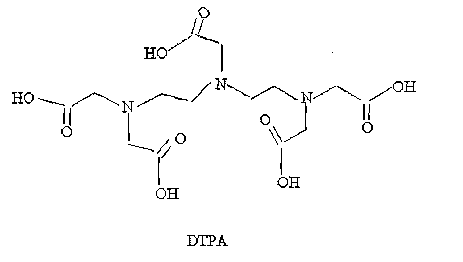

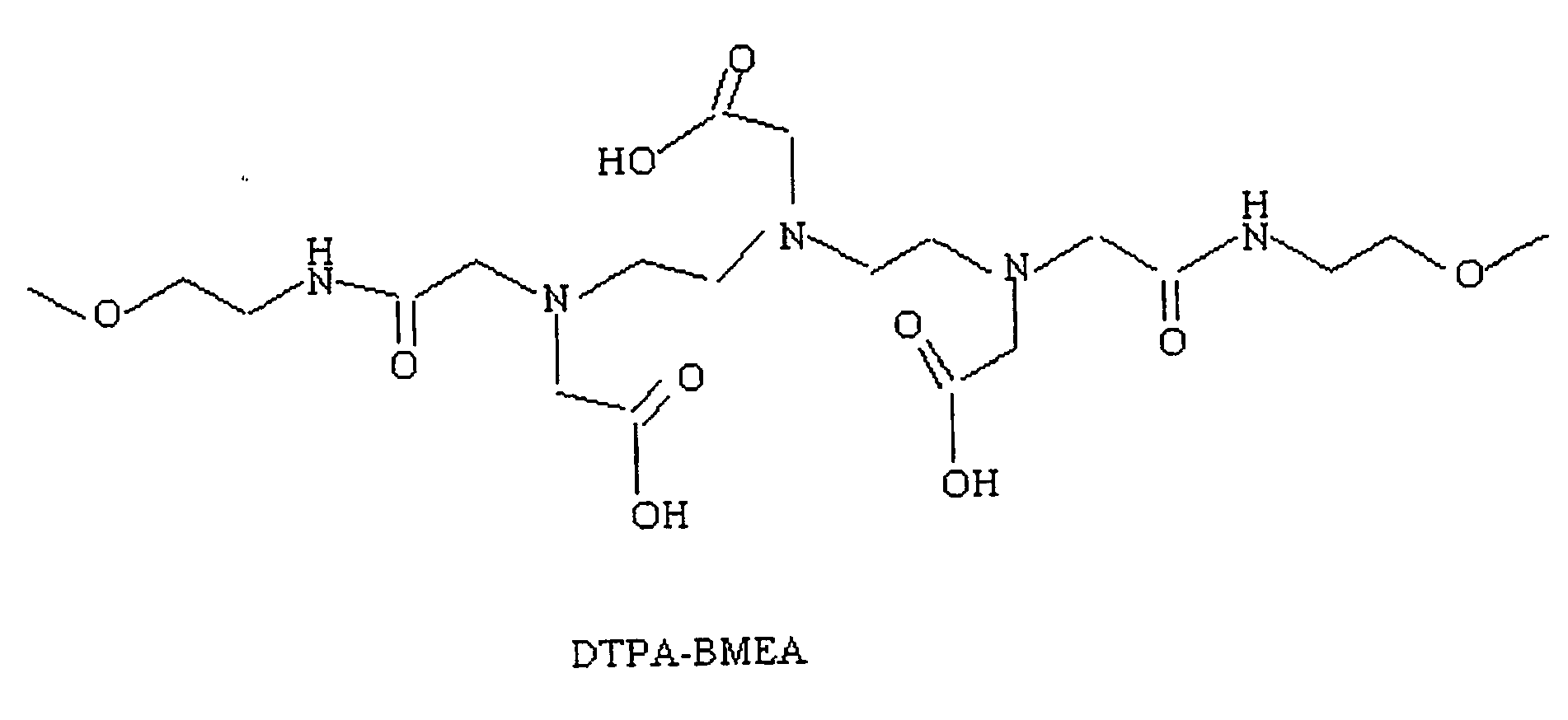


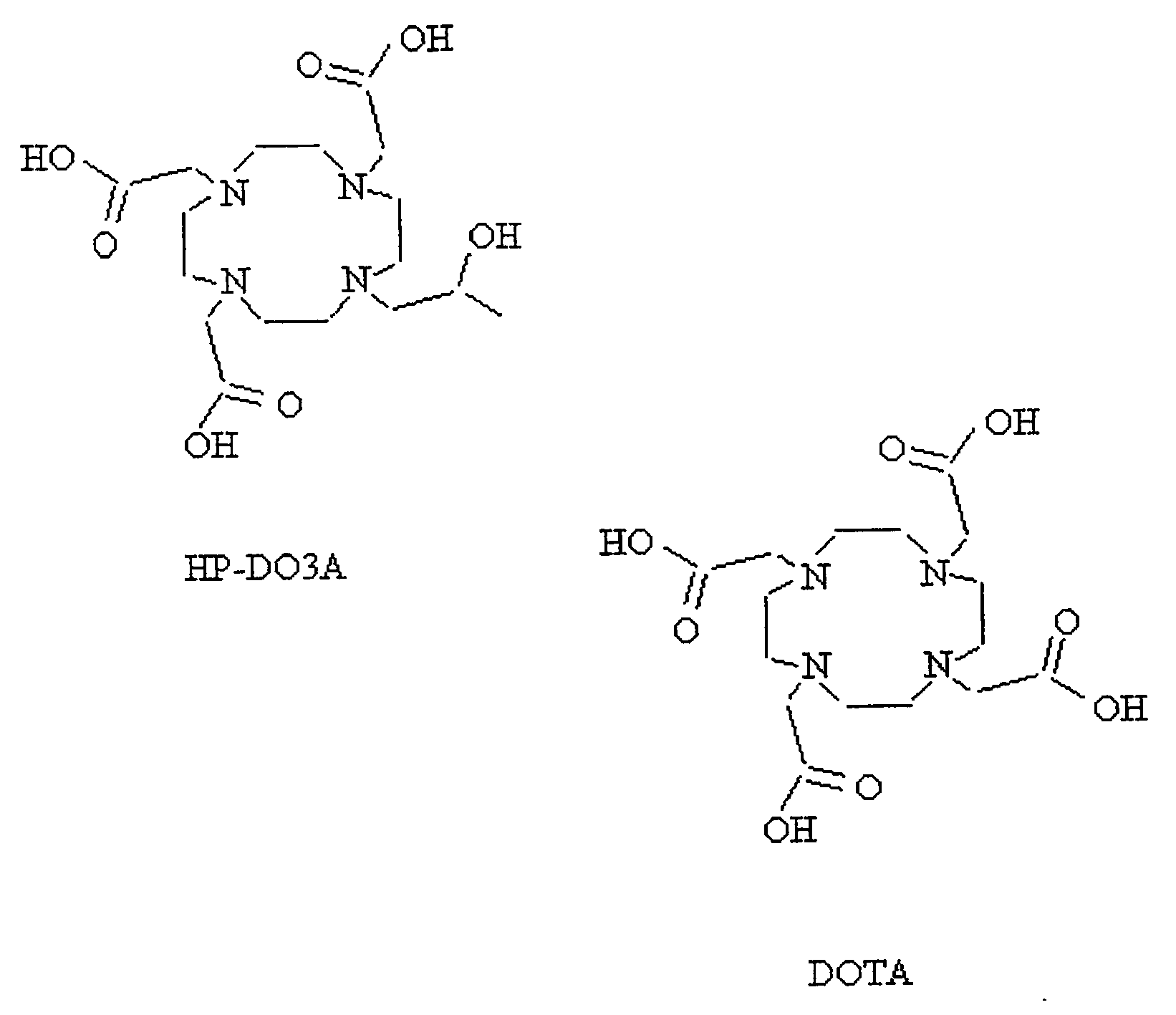

- As used herein, the term "paramagnetic-metal-ion/chelate complex" is meant to refer to a complex comprising one or more paramagnetic-metal ions (Mn+) coordinated with or bound to a chelate L. The paramagnetic-metal-ion/chelate complex may comprise any of the paramagnetic-metal ions or chelates discussed above and below. The paramagnetic-metal-ion/chelate complex may be designated by the following in the formulas described above and below: L-Mn+.
- As used herein, the term "chain" is meant to refer to a group of one or more atoms. The chain is a group of atoms that are part of a polymer or part of a hydrogel, a solid-base polymer, a polymer that is not covalently linked to a medical device or a second hydrogel.
- The paramagnetic metal ion is suitably a multivalent ion of paramagnetic metal including but not limited to the lanthanides and transition metals such as iron, manganese, chromium, cobalt and nickel. Preferably, Mn+ is a lanthanide which is highly paramagnetic, most preferred of which is the gadolinium(III) ion having seven unpaired electrons in the 4f orbital. It is noted that the gadolinium(III) (Gd (III)) ion is often used in MR contrast agents, i.e., signal influencing or enhancing agents, because it is highly paramagnetic and has a large magnetic moment due to the seven unpaired 4f orbital electrons. In such contrast agents, gadolinium(III) ion is generally combined with a chelating agent, such as DTPA. The resulting complex (Gd-DTPA or Magnevist; Berlex Imaging, Wayne, New Jersey) is very stable in vivo, and has a stability constant of 1023, making it safe for human use. Similar agents have been developed by chelating the gadolinium(III) ion with other complexes, e.g., MS-325, Epix Medical, Cambridge, Massachusetts. The gadolinium (III) causes a localized T1 reduction in the water protons in its environment, giving enhanced visibility in T1 weighed MR images. Because of the high signal caused by the coating by virtue of shortening of T1, the entirety of the coated devices can be readily visualized during, e.g., an endovascular procedure.
- The MR signal-emitting coatings in accordance with the present invention are synthesized according to a three or four-step process. The three-step method includes: (i) plasma-treating the surface of a polymeric material (or a material coated with a polymer) to yield surface functional groups, e.g., using a nitrogen-containing gas or vapor such as hydrazine (NH2NH2) to yield amino groups; (ii) binding a chelating agent, e.g., DTPA, to the surface functional group (e.g. through amide linkage); and (iii) coordinating a functional paramagnetic metal ion such as Gd(III) with the chelating agent. Alternatively, the surface may be coated with amino-group-containing polymers which can then be linked to a chelating agent. Generally, the polymeric material is a solid-base polymer from which the medical device is fabricated. It is noted that the linkage between the surface functional groups and the chelates is often an amide linkage. In addition to hydrazine, other plasma gases which can be used to provide surface functional amino groups include urea, ammonia, a nitrogen-hydrogen combination or combinations of these gases. Plasma gases which provide surface functional carboxyl groups include carbon dioxide or oxygen.
- The paramagnetic-metal-ion/chelate complex is covalently bonded to the medical device such that the complex is substantially non-absorbable by a living organism upon being inserted therein. The complex is also substantially non-invasive within the endovascular system or tissues such that non-specific binding of proteins are minimized. The complex of the present invention differs substantially from other methods in which a liquid contrasting agent is merely applied to a medical device. In other words, such a liquid contrasting agent is not covalently linked to the device, and therefore, is likely to be absorbed by the tissue into which it is inserted.
- A schematic reaction process of a preferred embodiment of the present invention is shown in
Figure 1 . As seen specifically inFigure 1 , polyethylene is treated with a hydrazine plasma to yield surface functionalized amino groups. The amino groups are reacted with DTPA in the presence of a coupling catalyst, e.g.,1,1'-cabonyldiimidazole, to effect an amide linkage between amino groups and DTPA. The surface amino-DTPA groups are then treated with gadolinium trichloride hexahydrate in an aqueous medium, coordinating the gadolinium (III) ion with the DTPA. - The MR-signal-emitting coatings are suitably made via a four-step process which is similar to the three-step process except that prior to step (ii), i.e., prior to reaction with the chelating agent, a linker agent or spacer molecule, e.g., a lactam, is bound to the surface functional groups, resulting in the coating is of formula (II).
- An illustrative schematic reaction process using a lactam or cyclic amide is shown in
Figure 2 . As seen inFigure 2 , a polyethylene with an amino functionalized surface is reacted with a lactam. The amino groups and lactam molecules are coupled via an amide linkage. It is noted that "m" in the designation of the amino-lactam linkage is suitably an integer greater than 1. The polyethylene-amino-lactam complex is then reacted with DTPA which forms a second amide linkage at the distal end of the lactam molecule. The last step in the process, coordinating the gadolinium (III) ion with the DTPA (not shown inFigure 2 ), is the same as shown inFigure 1 . - Specific reaction conditions for forming a coating in accordance with the present invention, which utilizes surface functionalized amino groups, include plasma treatment of a polymeric surface, e.g., a polyethylene surface, at 50 W power input in a hydrazine atmosphere within a plasma chamber, schematically represented in
Figure 3 , for 5-6 min. under 13 Pa to 106 Pa (100 mT-800 mT). - As seen in
Figure 3 , an exemplary plasma chamber, designated generally byreference numeral 20, includes a cylindrical stainlesssteel reaction chamber 22 suitably having a 20 cm diameter, alower electrode 24, which is grounded, and an upper electrode 26, both suitably constructed of stainless steel.Electrodes 24 and 26 are suitably 0.8 cm thick. Upper electrode 26 is connected to an RF-power supply (not shown). Both electrodes are removable which facilitates post-plasma cleaning operations.Lower electrode 24 also forms part of avacuum line 28 through a supporting conical-shaped and circularly-perforatedstainless steel tubing 30 that has a control valve 31. The evacuation ofchamber 22 is performed uniformly through a narrow gap (3 mm) existing betweenlower electrode 24 and the bottom ofchamber 22. Upper electrode 26 is directly connected to a threaded end of a vacuum-tight metal/ceramic feedthrough 32 which assures both the insulation of the RF-power line from the reactor and the dissipation of the RF-power to the electrodes. Aspace 34 between upper electrode 26 and the upper wall ofchamber 22 is occupied by three removable 1 cm thick, 20 cm diameter Pyrex™ glass disks 36.Disks 36 insulate upper electrode 26 from the stainless steel top of thereactor 20 and allow the adjustment of the electrode gap. The reactor volume located outside the perimeter of the electrodes is occupied by two Pyrex™ glass cylinders 38 provided with four symmetrically located through-holes 40 for diagnostic purposes. - This reactor configuration substantially eliminates the non-plasma zones of the gas environment and considerably reduces the radial diffusion of the plasma species, consequently leading to more uniform plasma exposure of the substrates (electrodes). As a result, uniform surface treatment and deposition processes (6-10% film thickness variation) can be achieved.
- The removable top part of the
reactor 20vacuum seals chamber 22 with the aid of a copper gasket andfastening bolts 42. This part of the reactor also accommodates a narrow circular gas-mixing chamber 44 provided with a shower-type 0.5 mm diameter orifice system, and a gas- andmonomer supply connection 46. This gas supply configuration assures a uniform penetration and flow of gases and vapors through the reaction zone. Theentire reactor 20 is thermostated by electric heaters attached to the outside surface ofchamber 22 and embedded in analuminum sheet 48 protecting a glass-wool blanket 50 to avoid extensive loss of thermal energy. - For diagnostic purposes, four symmetrically positioned stainless steel port hole tubings 51 are connected and welded through insulating
blanket 50 to the reactor wall. These port holes are provided with exchangeable, optically smooth, quartz windows 52. Avapor supply assemblage 54, as seen inFigure 3A , includes a plasma reservoir 56, valves 58,VCR connectors 60 and connectingstainless steel tubing 62.Assemblage 54 is embedded in two 1 cmthick copper jackets 64 20 provided with controlled electric heaters to process low volatility chemicals.Assemblage 54 is insulated using a glass-wool blanket coating. The thermostatic capabilities ofreactor 20 are in the range of 25-250°C. - Once the device to be coated is surface functionalized, it is then immersed in a solution of the chelating agent, e.g., DTPA, in, e.g., anhydrous pyridine, typically with a coupling catalyst, e.g., 1,1'-carbonyldiimidazole, for a time sufficient for the chelate to react with the amine groups, e.g., 20 hours. The surface is washed sequentially with at least one of the following solvents: pyridine, chloroform, methanol and water. The chelate-treated surface is then soaked in an aqueous solution of GdCl3.6H2O, for a time sufficient for the paramagnetic ion to react with the chelate, e.g., 12 hours. The surface is then washed with water to remove any uncoordinated, physisorbed Gd(III) ion.
- In test processes, each step has been verified to confirm that the bonding, in fact, occurs. For example, to verify the amino group functionalization, x-ray photoelectron spectroscopy (XPS) was used. A XPS spectrum of the polyethylene surface was taken prior to and after plasma treatment. The XPS spectrum of polyethylene before the treatment showed no nitrogen peak. After treatment, the nitrogen peak was 5.2% relative to carbon and oxygen peaks of 63.2% and 31.6%, respectively.
- To determine whether the amino groups were accessible for chemical reactions, after step (i) the surface was reacted with p-trifluorobenzaldehyde or p-fluorophenone propionic acid and rinsed with a solvent (tetrahydrofuran). This reactant, chosen because of good sensitivity of fluorine atoms to XPS, produces many photoelectrons upon x-ray excitation. The result of the XPS experiment showed a significant fluorine signal. The peaks for fluorine, nitrogen, carbon and oxygen were: 3.2%, 1.5%, 75.7% and 19.6%, respectively. This demonstrated that the amino groups were accessible and capable of chemical reaction.
- Because the coatings in accordance with the present invention are advantageously applied to catheters and because a catheter surface is cylindrical, it is noted that to coat commercial catheters, the plasma reaction must be carried out by rotating the catheter axis normal to the plasma sheath propagation direction. Such rotational devices are known and can be readily used in the plasma reactor depicted in
Figure 3 . To verify that surface amination occurs for such surfaces, atomic force microscopy (AFM) is used to study the surface morphology because XPS requires a well-defined planar surface relative to the incident X-ray. The coating densities (e.g., nmol Gd3+/m2) are measured using NMR and optimal coating densities can be determined. - It is also understood that metallic surfaces can be treated with the coatings in accordance with the present invention. Metallic surfaces, e.g., guide-wires, can be coated with the polymers set forth above, e.g., polyethylene, by various known surface-coating techniques, e.g., melt coating, a well known procedure to overcoat polymers on metal surfaces. Once the metallic surfaces are overcoated with polymer, all other chemical steps as described herein apply. In an example to be described below, we used commercial guide-wires which were previously coated with hydrophilic polymers.
- In a second embodiment of the invention, the magnetic resonance imageability of medical devices is enhanced or improved by encapsulating the medical device, or paramagnetic-metal-ion/chelate complexes linked thereto, with a hydrogel. As discussed above, catheters and other medical devices may be at least partially made or coated with a variety of polymers. The polymer surfaces of the existing medical devices are functionalized by plasma treatment or by melt coating with a hydrophilic polymer as discussed above or precoating with a hydrophilic polymer containing primary amine groups. Through amide linkage or α,ω-diamide linkage via a linker molecule, a chelating agent may be covalently bonded to the functionalized polymer surface. Subsequently, any of the paramagnetic-metal ions discussed above, e.g. Gd(III), can be complexed to the chelate. The necessary contrast for MRI is the result of interactions of protons in body fluid (e.g., blood) or bound within the encapsulating hydrogel with the highly magnetic ion, and the resulting shortening of T1 relaxation time of the proton. It has been discovered that by reducing the mobility of the paramagnetic-metal-ion/chelate complex without affecting the exchange rate of one molecule of water coordinating to the paramagnetic metal ion, the MR-imageability of the medical device is enhanced and improved. In other words, if the movement of these complexes is restricted, the MR-imageability of the polymer to which the complex is attached is greatly improved.
- Therefore, it has been found that one way by which to reduce the mobility of the complex for imaging is to encapsulate the medical device, and more particularly, the complex in a hydrogel. The hydrogel reduces the mobility of the paramagnetic-metal-ion/chelate complexes without significantly affecting the rate of water molecule exchange on the complexes, thereby enhancing the magnetic-resonance imageability of the medical devices. There is a delicate balance between slowing of the rotational relaxation time of the paramagnetic-metal-ion/chelate complexes and retardation of the exchange rate of water molecules from inner coordination sphere of the Mn+ to the bulk water molecules diffusing in the outer coordination sphere of Mn+. The reason for MR imageability for free paramagnetic-metal-ion/chelate complexes without being bonded to polymer surface comes about because of a much greater concentration of the complex in solution compared with that bound to the surface.
- Examples of suitable hydrogels include, but are not limited to, at least one of collagen, gelatin, hyaluronate, fibrin, alginate, agarose, chitosan, poly(acrylic acid), poly(acrylamide), poly(2-hydroxyethyl methacrylate), poly(N-isopropylacrylamide), poly(ethylene glycol)/poly(ethylene oxide), poly(ethylene oxide)-block-poly(lactic acid), poly(vinyl alcohol), polyphosphazenes, polypeptides and combinations thereof. Any hydrogel or similar substance which reduces the mobility of the paramagnetic-metal-ion/chelate complex can also be used, such as physical hydrogels that can be chill-set without chemical cross-linking. In addition, overcoating of high molecular weight, hydrophilic polymers can be used, e.g., poly(acrylic acid), poly(vinyl alcohol), polyacrylamide, having a small fraction of functional groups that can be linked to residual amino groups are suitable for use with the invention. The MR-imageability of other MR-imageable devices made by methods other than those described herein may also be improved by coating other devices with the hydrogels described above.
- The devices can be encapsulated using a variety of known encapsulating techniques in the art. For example, a gel may be melted into a solution, and then the device dipped into the solution and then removed. More particularly, the gel may be dissolved in distilled water and heated. Subsequently, the solution coating the device is allowed to dry and physically self assemble to small crystallites that may adsorb to the polymer surface of the medical device and also play the role of cross-links. Such a phenomenon is commonly referred to as "chill-set" since it arises from thermal behavior of gelling systems.
- The gel may also be painted onto the medical device. Alternatively, the medical device may be encapsulated by polymerization of a hydrophilic monomer with a small fraction of cross-linker that participates in the polymerization process. For example, a medical device may be immersed in a solution of acrylamide monomer with bisacrylamide as the cross-linker and a photo-initiator, and the polymerization is effected with ultra-violet (UV) irradiation to initiate the polymerization in a cylindrical optical cell.
- Alternatively, the medical device may be dipped into a gelatin solution in a suitable concentration (e.g., 5%), and mixed with a cross-linker such as glutaraldehyde. As used herein, the term "cross-linker" is meant to refer to any multi-functional chemical moiety which can connect two or a greater number of polymer chains to produce a polymeric network. Other suitable cross-linkers include, but are in no way limited to, BVSM (bis-vinylsulfonemethane) and BVSME (bis-vinylsulfonemethane ether). Any substance that is capable of cross-linking with the hydrogels listed above is also suitable for use with the invention. Upon removing the device from the gelatin solution and letting it dry, the cross-linking takes place to encapsulate the entire coated assembly firmly with a sufficient modulus to be mechanically stable.
- Typically, encapsulation is repeated until the desired thickness of the gel is obtained. The thickness of the encapsulated-hydrogel layer may be about 10 to about 60 microns, although it may be less and it may be more. In other words, the surface may be "primed" and then subsequently "painted" with a series of "coats" of gel until the desired thickness of the gel layer is obtained. Alternatively, the gel concentration is adjusted to bring about the desired thickness in a single coating process. In order to test the effectiveness of coating these devices with hydrogels to enhance the MR-imageability of the medical device, three samples were prepared and tested as set forth and fully described in Example 10 below.
- Example 11 below also describes in more detail how one example of the second embodiment of the invention can be made. Moreover,
Figure 13 is a schematic representation of one example of the second embodiment of the invention, wherein a polyethylene rod, surface coated with amine-linked polymers, is chemically linked with DTPA, which is coordinated with Gd(III). The rod, polymer, DTPA and Gd(III) are encapsulated with a soluble gelatin, which is cross-linked with glutaraldehyde to form a hydrogel overcoat.Figure 14 shows the chemical details for the example schematically represented inFigure 13 . - The second embodiment may be summarized as a coating for improving the magnetic-resonance imageability of a medical device comprising a complex of formula (III). The method includes encapsulating at least a portion of the device having at least one of the paramagnetic-metal-ion/chelate complexes covalently linked thereto with a hydrogel. The complex of formula (III) follows:
(P - X- L - Mn+)gel (III),
wherein P is a base polymer substrate from which the device is made or with which the device is coated; X is a surface functional group; L is a chelate; M is a paramagnetic ion; n is an integer that is 2 or greater; and subscript "gel" stands for a hydrogel encapsulate. - In a third embodiment of the invention, a polymer having functional groups is chemically linked with one or more of the chelates described above. More particularly, the polymer having a functional group (e.g. an amino or a carboxyl group) is chemically linked to the chelate via the functional group. In addition to the polymers set forth above, an example of a suitable polymer having functional groups is, but should not be limited to, poly(N[3-aminopropyl]methacrylamide), which has the following repeating unit structure:

- The third embodiment alleviates the need for a precoated polymer material on the medical device, or a medical device made from a polymer material. In other words, the third embodiment alleviates the need to link the paramagnetic-metal-ion/chelate complex to the surface of the medical device, when the medical device is made from or coated with a polymer. Instead, the polymer having functional groups, preferably poly(N[3-aminopropyl] methacrylamide), can be synthesized separately and then covalently linked to the chelate (e.g. DTPA) through functional groups (e.g. amine groups) on the polymer. Instead of linking the complex to the surface of the medical device, the polymer and complex are coordinated separately, and then added to a hydrogel. The chelate may be coordinated with the paramagnetic-metal ion (e.g. Gd(III)), and then mixed with soluble gelatin and used to coat a bare (i.e. uncoated) polyethylene rod. Subsequently, the gelatin is chill-set and then the binary matrix of gelatin and polymer may be cross-linked with a cross-linker such as glutaraldehyde. The polymer used in connection with this embodiment may be a poly(N[3-aminopropyl] methacrylamide), the chelate may be DTPA and the paramagnetic-metal ion may be Gd(III). In addition, the hydrogel may be gelatin and the cross-linker may be glutaraldehyde. Typically, the surface of the medical device may be polyethylene. Again, in addition to these specific compounds, any of the polymers, chelates, paramagnetic-metal ions, hydrogels and cross-linkers discussed above are also suitable for use with this embodiment of the invention.
- Example 12 below describes in more detail how one example of the third embodiment of the invention can be made.
Figure 16 is a schematic representation of one example of the third embodiment of the invention, wherein a polymer is chemically linked with DTPA, coordinated with Gd(III) and mixed with soluble gelatin. The resulting mixture is applied to a bare (i.e. uncoated) polyethylene surface and cross-linked with glutaraldehyde to form a hydrogel overcoat.Figure 17 shows the chemical details for the example schematically represented inFigure 16 . - The third embodiment may be summarized as a coating for visualizing medical devices in magnetic resonance imaging comprising a complex of formula (IV). The method includes encapsulating at least a portion of the medical device with a hydrogel, wherein at least one of the paramagnetic-metal-ion/chelate complexes covalently linked to a polymer is dispersed in the hydrogel. The complex of formula (IV) follows:
(S...P'-X- L - Mn+)gel (IV)
wherein S is a medical device substrate not having functional groups on its surface; P' is a polymer with functional groups X, the polymer not being linked to the surface of the medical device; L is a chelate; M is a paramagnetic ion; n is an integer that is 2 or greater; and subscript "gel" stands for a hydrogel encapsulate. - In a fourth embodiment of the invention, a hydrogel having functional groups can be used instead of a primary polymer. For example, gelatin may be used instead of the polymers discussed above. Accordingly, the gelatin or hydrogel rather than the polymer may be covalently linked with a chelate. The gelatin, e.g., may be covalently linked to a chelate such as DTPA through the lysine groups of gelatin. In addition, hydrogels that are modified to have amine groups in the pendant chains can be used instead of the polymer, and can be linked to chelates using amine groups. The chelate is coordinated with a paramagnetic-metal ion such as Gd(III) as described above with respect to the other embodiments to form a paramagnetic-metal ion/chelate complex, and then mixed with a soluble hydrogel such as gelatin. The soluble hydrogel may be the same or may be different from the hydrogel to which the paramagnetic-metal ion/chelate complex is linked. The resulting mixture is used to coat a substrate or, e.g., a bare polyethylene rod. More particularly, the mixture is used to coat a medical device using the coating techniques described above with respect to the second embodiment. The coated substrate or medical device may then be chill-set. Subsequently, the hydrogel matrix or, for example, the gelatin-gelatin matrix may then be cross-linked with a cross-linker such as glutaraldehyde. The cross-linking results in a hydrogel overcoat, and a substance which is MR-imageable.
- Example 13 below describes in more detail how one example of the fourth embodiment of the invention can be made.
Figure 19 is a schematic representation of one example of the fourth embodiment of the invention, wherein gelatin is chemically linked with DTPA, which is coordinated with Gd(III) and mixed with free soluble gelatin without any DTPA linked. The resulting mixture of gelatin and DTPA[Gd(III)] complex coats a bare polyethylene surface, and is then cross-linked with glutaraldehyde to form a hydrogel coat with DTPA[Gd(III)] dispersed therein.Figure 20 shows the chemical details for the example schematically represented inFigure 19 . - The fourth embodiment can be summarized as a coating for visualizing medical devices in magnetic resonance imaging comprising a complex of formula (V). The method includes encapsulating at least a portion of the medical device with a hydrogel, wherein the hydrogel is covalently linked with at least one of the paramagnetic-metal-ion/chelate complexes. The complex of formula (V) follows:
(S...G-X-L-Mn+)gel (V)
wherein S is a medical device substrate which is made of any material and does not having any functional groups on its surface; G is a polymer with functional groups X that can also form a hydrogel encapsulate; L is a chelate; M is a paramagnetic ion; n is an integer that is 2 or greater; and subscript "gel" stands for a hydrogel encapsulate. - The present invention is further explained by the following examples. A description of the preparation and evaluation of MR-imageable PE polymer rods follows.
- Polyethylene sheets were coated in the three-step process described herein.
- Surface Amination. A polyethylene sheet (4.5 in diameter and 1 mil thick) was placed in a capacitively coupled, 50 kHz, stainless steel plasma reactor (as shown schematically in
Figures 3 and 3A ) and hydrazine plasma treatment of the polyethylene film was performed. The substrate film was placed on the lower electrode. First, the base pressure was established in the reactor. Then, the hydrazine pressure was slowly raised by opening the valve to the liquid hydrazine reservoir. The following plasma conditions were used: base pressure = 60 mT; treatment hydrazine pressure = 350 mT; RF Power = 25 W; treatment time = 5 min; source temperature (hydrazine reservoir) = 60°C; temperature of substrate = 40°C. Surface atomic composition of untreated and plasma-treated surfaces were evaluated using XPS (Perkin-Elmer Phi-5400; 300 W power; Mg source; 15 kV; 45° takeoff angle). - DTPA Coating. In a 25 mL dry flask, 21.5 mg of DTPA was added to 8 mL of anhydrous pyridine. In a small vessel, 8.9 mg of 1,1'-carbonyldiimidazole (CDI), as a coupling catalyst, was dissolved in 2 mL of anhydrous pyridine. The CDI solution was slowly added into the reaction flask while stirring, and the mixture was stirred at room temperature for 2 hours. The solution was then poured into a dry Petri dish, and the hydrazine-plasma treated polyethylene film was immersed in the solution. The Petri dish was sealed in a desiccator after being purged with dry argon for 10 min. After reaction for 20 hours, the polyethylene film was carefully washed in sequence with pyridine, chloroform, methanol and water. The surface was checked with XPS, and the results showed the presence of carboxyl groups, which demonstrate the presence of DTPA.
- Gadolinium (III) Coordination. 0.70 g of GdCl3·6H2O was dissolved in 100 mL of water. The DTPA-treated polyethylene film was soaked in the solution for 12 hr. The film was then removed from the solution and washed with water. The surface was checked with XPS and showed two peaks at a binding energy (BE) = 153.4 eV and BE = 148.0 eV, corresponding to chelated Gd3+ and free Gd3+, respectively. The film was repeatedly washed with water until the free Gd3+ peak at 148.0 eV disappeared from the XPS spectrum.
- The results of the treatment in terms of relative surface atomic composition are given below in Table 1.
Table 1 Relative Surface Atomic Composition of untreated and treated PE surfaces %Gd %N %O %C Untreated PE 0.0 0.0 2.6 97.4 Hydrazine plasma treated PE 0.0 15.3 14.5 70.2 DTPA coated PE 0.0 5.0 37.8 57.2 Gd coated PE 1.1 3.7 35.0 60.3 - Coated polyethylene sheets were prepared according to the method of Example 1, except that after surface amination, the polyethylene sheet was reacted with a lactam, and the sheet washed before proceeding to the chelation step. The surface of the film was checked for amine groups using XPS.
- MR signal enhancement was assessed by imaging coated sheets of polyethylene and polypropylene, prepared as described in Example 1, with gradient-recalled echo (GRE) and spin-echo (SE) techniques on a clinical 1.5 T scanner. The sheets were held stationary in a beaker filled with a tissue-mimic, fat-free food-grade yogurt, and the contrast-enhancement of the coating was calculated by normalizing the signal near the sheet by the yogurt signal. The T1-weighed GRE and SE MR images showed signal enhancement near the coated polymer sheet. The T1 estimates near the coated surface and in the yogurt were 0.4 s and 1.1 s, respectively. No enhancement was observed near control sheets. The MR images acquired are shown in
Figure 4 . - The following examples demonstrated the utility of DTPA[Gd(III)] in visualizing a catheter under MR guidance.
- A DTPA[Gd(III)] filled single lumen catheter 3-6 French (1-2 mm) was imaged in an acrylic phantom using a conventional MR Scanner (1.5T Signa, General Electric Medical Systems) while it was moved manually by discrete intervals over a predetermined distance in either the readout direction or the phase encoding direction. The phantom consisted of a block of acrylic into which a series of channels had been drilled. The setup permitted determination of the tip position of the catheter with an accuracy of ± 1 mm (root-mean-square). Snapshots of the catheter are shown in
Figure 5 . - For in vivo evaluation, commercially-available single lumen catheters filled with DTPA[Gd(III)] (4-6% solution), ranging in size between 3 and 6 French (1-2 mm), and catheter/guide-wire combinations were imaged either in the aorta or in the carotid artery of four canines. All animal experiments were conducted in conjunction with institution-approved protocols and were carried out with the animals under general anesthesia. The lumen of the catheter is open at one end and closed at the other end by a stopcock. This keeps the DTPA[Gd(III)] solution in the catheter. The possibility of DTPA[Gd(III)] leaking out of the catheter lumen through the open end was small and is considered safe because the DTPA[Gd(III)] used in these experiments is commercially available and approved for use in MR. Reconstructed images made during catheter tracking were superimposed on previously acquired angiographic "roadmap" images typically acquired using a 3D TRICKS imaging sequence (F.R. Korosec, R. Frayne, T.M. Grist, C.A. Mistretta, Magn. Reson. Medicine. 1996, 36 345-351, incorporated herein by reference) in conjunction with either an intravenous or intra-arterial injection of DTPA[Gd(III)] (0.1 mmol/kg). On some occasions, subtraction techniques were used to eliminate the background signal from the catheter images prior to superimposing them onto a roadmap image. Snapshots of the canine carotids and aortas are shown in
Figures 6 and7 , respectively. - Using canines, a catheter coated with a coating in accordance with the present invention/guide-wire combination is initially positioned in the femoral artery. Under MR guidance, the catheter is moved first to the aorta, then to the carotid artery, then to the circle of Willis, and on to the middle cerebral artery. The catheter movement is clearly seen in the vessels. The length of time to perform this procedure and the smallest vessel successfully negotiated is recorded.
- A gadolinium leaching test is performed to ascertain the stability of the DTPA[Gd(III)] complex. Polyethylene sheets coated with a coating in accordance with the present invention are subjected to simulated blood plasma buffers and blood plasma itself. NMR scans are taken and distinguish between chelated Gd3+ and free Gd3+. The results indicate that the Gd3+ complex is stable under simulated blood conditions.
- A biocompatibility test, formulated as non-specific binding of serum proteins, is carried out on polymeric surfaces coated in accordance with the present invention using an adsorption method of serum albumin labeled with fluorescent dyes. If the albumin is irreversibly adsorbed as detected by fluorescence of coated catheter surfaces, the coat is adjudged to be not biocompatible.
- A clinical 1.5 T scanner (Signa, General Electric Medical Systems) is used to determine the optimal range of coating densities (in mmol Gd3+/m2) for producing appreciable signal enhancement on a series of silicon wafers coated with a polyethylene-Gd-containing coating in accordance with the present invention. The wafers are placed in a water bath and scanned cross-sectionally using a moderately high-resolution fast gradient-recalled echo (FGRE) sequence with TR≈7.5 ms/TE ≈ 1.5 ms, 256 X 256 acquisition matrix and a 16 cm X 16 cm field-of-view (FOV). The flip angle is varied from 10° to 90° in 10° increments for each coating density. A region of interest (ROI) is placed in the water adjacent to the wafer and the absolute signal is calculated.
- For calibration of signal measurements obtained in different imaging experiments, a series of ten calibration vials is also imaged. The vials contain various concentrations of DTPA[Gd(III)], ranging from 0 mmol/mL to 0.5 mmol/mL. This range of concentrations corresponds to a range of T1 relaxation times (from <10 ms to 1000 ms) and a range of T2 relaxation times. The signals in each vial are also measured and used to normalize the signals obtained near the wafers. Normalization corrections for effects due to different prescan settings between acquisitions and variable image scaling are applied by the scanner. A range of concentrations in the vials facilitates piece-wise normalization. An optimal range of coating densities is determined.
- Because many medical devices are made of polyethylene (PE), PE rods were used in a variety of tests in order to mimic the surface of a catheter or medical device. In this specific example (as fully set forth in the preparation of Sample 2), the PE rods (2mm diameter) were functionalized or precoated with a hydrophilic polymer containing primary amine groups. Through amide linkage, diethylenetrimaminepentaacetic acid (DTPA) was covalently attached to the rods. Subsequently, Gd(III) was complexed to the DTPA. The necessary contrast for MRI is the result of interactions of proton of water in body fluid (e.g., blood) with the highly magnetic Gd(III) ion, and the resulting shortening of T1 relaxation time of the water protons. To reduce the mobility of the DTPA[Gd(III)] complex for imaging in accordance with the present invention agarose gel was used to encapsulate the entire assembly. Such a rod was used as
Sample 2 in the testing as further described below. - To test the effectiveness of agarose gel in reducing the mobility of the DTPA[Gd(III)] complex, and accordingly, enhancing the MR-imageability of the medical device, two other samples were tested in parallel.
Sample 1 was a blank sample, i.e. a PE rod encapsulated with agarose gel but having no DTPA[Gd(III)] complexed to the rod;Sample 3 was a PE rod encapsulated with agarose gel containing a DTPA[Gd(III)] complex, but the complex was not covalently linked to the PE rods. MRI tests were carried out in three media: 1) a fat-free food-grade yogurt (a tissue mimic); 2) a physiological saline (a serum mimic); and 3) human blood. In summary, the following three agarose-encapsulated samples were tested in each media: the blank sample having no DTPA[Gd(III)] complex, but encapsulated in agarose (Sample 1); the chemically-bound or covalently linked DTPA[Gd(III)] complex encapsulated in agarose (Sample 2); and the unbound DPTA[Gd(III)] encapsulated in agarose (Sample 3).Sample 1, the blank, gave no detectable MRI signal.Sample 2 gave clearly detectable signals up to ten hours.Sample 3 lost signal intensity with time, thereby indicating a slow leaching of DTPA[Gd(III)] complex from the agarose gel matrix because it was not covalently bound to the polymer of the medical device. Given the observed MR images ofSamples - Specific preparation and evaluation of MR-imageable PE polymer rods is as follows.
-
Sample 1 was prepared by coating blank PE rods with agarose gel. The PE rods forSample 1 and all samples were obtained from SurModics, Inc. located at 9924 West 74th Street, Eden Prairie, Minnesota 55344-3523. Agarose (type VI-A) was purchased from Sigma located in St. Louis, Missouri, with gel point (1.5% gel) at 41.0° ± 1.5°C, gel strength (1.5%) expressed in units of elastic modulus larger than 1200g/cm2, and melting temperature 95.0° ± 1.5°C. 0.60 g agarose was dissolved in 40 mL distilled water in a flask maintained at 100°C for 5 min. The solution was kept in a water bath at 50-60°C. The PE rods were then dipped into the agarose solution. After removing the rods from the solution, the rods were cooled to room temperature in order to allow a gel-coating to form on the rod surface. The same procedure was repeated to overcoat additional layers of agarose, and it was repeated for 5 times for each rod. Thus, all rods were expected to have about the same gel-coating thickness. - Polyethylene (PE) rods with an amine-containing-polymer coating were provided by SurModics, Inc. SurModics, Inc. functionalizes the PE surface of the rods by a photochemical attachment of poly(2-aminoethyl methacrylate) in order to provide functional groups, more specifically, amine groups, on the functionalized surface of the rods. Again, the PE rods in the example were meant to mimic the surface of existing medical devices made from a wide variety of polymers. Diethylenetriaminepentaacetic acid (DTPA), gadolinium trichloride hexahydrate, GdCl3·6H2O (99.9%), dicyclohexylcarbodiimide (DCC), and 4-(dimethylamino)-pyridine (DMAP) were all purchased from Aldrich located at Milwaukee, Wisconsin, and used without further purification. Agarose (type VI-A) was purchased from Sigma located at St. Louis, Missouri, with gel point (1.5% gel) at 41.0° ± 1.5°C, gel strength (1.5%) larger than 1200g/cm2, and melting temperature 95.0° ± 1.5°C. Human blood used in the MRI experiments were obtained from the University of Wisconsin Clinical Science Center Blood Bank located in Madison, Wisconsin.
- The MRI-signal-emitting coatings were prepared on the PE rods, i.e. the pre-existing rods were made MR-imageable, by the chemical synthesis depicted in
Figure 8 . The individual steps of the chemical synthesis are explained in detail below. - To attach the DTPA (i.e. chelate) to the PE rods by amide linkage, 0.165 g DTPA (0.42 mmol) was dissolved in 30 mL of 1:1 (by volume) mixture of pyridine and DMSO in a flask and stirred at 80°C for 30 min. Subsequently, 5-cm long PE rods having the amine-containing-polymer coating were immersed in the solution. After stirring for 2 hours at room temperature, 0.090 g DCC (0.43 mmol) and 0.050 g DMAP (0.41 mmol) solution in pyridine (4mL) was slowly added to the solution while stirring. Then the reaction mixture was kept in an oil bath at 60°C for 24 hours while stirring. Subsequently, the PE rods were removed from the solution and washed three times - first with DMSO and then with methanol, respectively.
- To complex or coordinate Gd(III) with the DTPA, now linked to the PE rods, 0.140 g GdCl3·6H2O (0.38 mmol) was dissolved in 15 mL of distilled water in a test tube. The DTPA-linked-PE rods were soaked in this solution at room temperature for 24 hours while stirring. The rods were then washed with distilled water several times and soaked in distilled water for an additional hour to remove any residual GdCl3.
- To encapsulate the PE rods in the final step of the chemical synthesis as shown in
Figure 8 , 0.60 g agarose was dissolved in 40 mL distilled water in a flask maintained at 100°C for 5 min. The agarose solution so obtained was then kept in a water bath at 50-60°C. The DTPA[Gd(III)] linked rods were then dipped into the agarose solution. After removing the rods from the agarose solution, the rods were cooled down to room temperature in order to allow for encapsulation, i.e., to allow the gel coating to cover the rod surface. The same procedure was repeated 5 times to coat additional layers of agarose gel on the rods. Thus, all rods, having undergone the same procedure, were expected to have about the same gel-coating thickness. -
Sample 3 was prepared by coating PE rods with agarose gel and a DTPA[Gd(III)] mixture. 0.45 g agarose (also obtained from Sigma) was dissolved in 30 mL distilled water in a flask maintained at 100°C for 5 min. Then, 3 mL of 0.4% solution of DTPA[Gd(III)] was added to the agarose solution. The solution was kept in a water bath at 50-60°C. The rods were dipped into the agarose solution, and then were removed. The adsorbed solution on the rod was cooled to room temperature to allow a gel-coating to form. The same procedure was repeated to coat additional layers of agarose, and it was repeated for 5 times altogether for each rod. Thus, all rods were expected to have about the same gel coating thickness.Sample 3 differed fromSample 2 in that the DTPA[Gd(III)] complex was not covalently bonded to the PE rod using the methods of the present invention. Instead, a DTPA[Gd(III)] mixture was merely added to the agarose solution, resulting in dispersion of the same in the gel upon encapsulation in 5-layer coating. - The samples were then subjected to characterization by x-ray photoelectron spectroscopy (XPS) and magnetic resonance (MR) measurements. XPS measurements were performed with a Perkin-Elmer Phi 5400 apparatus. Non-monochromatized MgKα X-ray has been utilized at 15W and 20mA, and photoelectrons were detected at a take-off angle of 45°. The survey spectra were run in the binding energy range 0-1000 eV, followed by high-resolution spectra of C(1s), N(1s), O(1s) and Gd(4d).
- MR evaluation of the signal-emitting rods was performed on a clinical 1.5T scanner. The PE rods were each imaged in the following medium: 1) yogurt as a suitable tissue mimic; 2) saline as an electrolyte mimic of blood serum; and 3) and human blood. Spin echo (SE) and RF spoiled gradient-recalled echo (SPGR) sequences were used to acquire images.
- The surface chemical composition of the rods was determined by the XPS technique. Table 2, below, lists the relative surface atomic composition of the untreated rods as provided by SurModics (Eden Prairie, MN). Table 3 shows the relative surface composition of the treated (DTPA[Gd(III)] linked) rods. After the chemical treatment outlined in
Figure 8 , the relative composition of oxygen increased from 10.8% to 25.9% as seen in Tables 2 and 3. This indicates that DTPA is indeed attached to the polymer surface. Furthermore, it is clear that Gd(III) was complexed to the DTPA on the polymer surface, thus giving rise to the surface Gd composition of 3.2%.Table 2 Surface compositions in % of 3 elements, C, N and O, of PE rods coated with the NH2-containing polymer (SurModics). Location C(1s) N(1s) O(1s) 1 80.7 8.6 10.7 2 80.2 8.3 11.5 3 80.4 9.3 10.3 average 80.4 (±0.3) 8.7 (±0.5) 10.8 (±0.6) Table 3 Surface composition in % of 4 elements of the PE rods linked with DTPA[Gd(III)] Location C(1s) N(1s) O(1s) Gd(4d) 1 65.2 5.8 25.9 3.1 2 63.2 7.2 26.5 3.1 3 63.6 7.8 25.2 3.3 average 64.0 (±1.0) 6.9 (±1.0) 25.9 (±0.7) 3.2 (±0.1) - The polymer rods linked with DTPA[Gd(III)] and encapsulated by agarose gel (Sample 2) were imaged in yogurt, saline and human blood. At the same time, the control rods, i.e., the PE rods having no chemical treatment but having only the gel overcoat (Sample 1) as well as PE rods coated with the gel in which DTPA[Gd(III)] is dispersed but not covalently linked (Sample 3) were also imaged in yogurt, saline and blood using spin echo (SE) and RF spoiled gradient-recalled echo (SPGR) sequences. Typical scan parameters for 2D SE sequence were: TR = 300 ms, TE = 9 ms, acquisition matrix = 256
X 256, FOV = 20cm X 20 cm, slice thickness = 3 mm, flip angle = 30°. Typical scan parameters for 3D SPGR sequence were: TR = 18 ms, TE = 3.7 ms. acquisition matrix = 256X 256, FOV = 20cm X 20 cm, slice thickness = 3 mm, flip angle = 30°. The three kinds of samples and the MRI imaging set-up are illustrated inFigure 9 . - The rods were imaged, the results of which are shown in
Figures 10-12 . More particularly,Figure 10 shows the longitudinal MR image of each sample in each medium after 15+ minutes;Figure 11 shows the longitudinal MR images after 60+ minutes; andFigure 12 shows the longitudinal MR images of each sample in each medium after 10+ hours. As these figures illustrate, Sample 1 (i.e. PE rods coated only with the gel and without DTPA[Gd(III)]) is not visible in all three media, yogurt, saline, or blood. Sample 2 (i.e. PE rods covalently-linked with DTPA[Gd(III)] with overcoats of the gel) is visible in yogurt, saline, and blood and was clearly visible even after 10 hours as shown inFigure 12 .Sample 3 is also visible in yogurt, saline, and blood; however, DTPA[Gd(III)] appears to leach and diffuse out of the gel overcoat with time because it is not covalently bonded to the polymer rod. For example, after 10 hours,sample 3 is not visible in saline or blood. - The summary of the MR experiments is presented in Table 4. Consequently, Sample 2 (having DTPA[Gd(III)] covalently linked to polyethylene) exhibits better MR-imageability for longer periods of time compared to
Sample 1 andSample 3. In addition, it appears that encapsulating rods or medical devices having the paramagnetic-metal-ion/chelate complex covalently linked thereto with a hydrogel improves or enhances the MR-imageability thereof. In Table 4, a "+" indicates that the sample was visible, while "-" indicates that the sample was not visible.Table 4 MR signals of the samples in yogurt, saline and blood. Time 20 mins 2 hours 10 hours 10 hours and replace the yogurt and blood In yogurt 1 - - - - 2 + + + + 3 + +, but the signal diffused and became bigger +, but the signal diffused much + In saline 1 - - - - 2 + + +, and the signal as strong as that of 20 mins +, and the signal as strong as that of 20 mins 3 + +, but decreased - - In blood 1 - - - - 2 + + + + 3 + +, but decreased - - - Diethylenetriaminepentaacetic acid (DTPA), gadolinium trichloride hexahydrate, GdCl3·6H2O (99.9%), dicyclohexylcarbodiimide (DCC), 4-(dimethylamino)-pyridine (DMAP), dimethyl sulfoxide(DMSO), and pyridine were all purchased from Aldrich, Milwaukee, Wisconsin, and used without further purification. Gelatin type (IV) was provided by Eastman Kodak Company as a gift. Glutaraldehyde(25% solution) was purchased from Sigma, St. Louis, Missouri. These materials were used in Example 11, as well as Examples 12-13.
- 0.165 g DTPA (0.42 mmol) was dissolved in 30 mL of 2:1 (by volume) mixture of pyridine and DMSO in a flask and stirred at 80° C for 30 min. Then, a 40-cm long polyethylene (PE) rod (diameter 2mm) with the amine containing polymer precoating were immersed in the solution. The PE rods with an amine-containing-polymer coating were provided by SurModics, Inc. SurModics, Inc. functionalizes the PE surface of the rods by a photochemical attachment of poly(2-aminoethyl methacrylate) in order to provide functional groups, more specifically, amino groups, on the functionalized surface of the rods. Again, the PE rods were meant to mimic the surface of existing medical devices made from a wide variety of polymers. After stirring for 2 hours at room temperature, a pyridine solution (4mL) containing amidation catalysts, 0.090 g DCC (0.43 mmol) and 0.050 g DMAP (0.41mmol), was slowly added to the PE rod soaked solution with stirring. Subsequently, the reaction mixture was kept in an oil bath at 60° C for 24 hours with stirring to complete the bonding of DTPA to the amine groups on the precoated polymer via amide linkage. Subsequently, the PE rods were removed from the solution and washed three times first with DMSO and then with methanol.
- 0.50 g GdCl3· 6H2O (0.38 mmol) was dissolved in 100 mL distilled water in a test tube. The DTPA linked PE rods (40-cm long) were soaked in the solution at room temperature for 24 hours while stirring, then the rods were washed with distilled water several times to remove the residual GdCl3.
- A sample of gelatin weighing 20 g was dissolved in 100 mL of distilled water at 60° C for 1 hour with stirring. The solution was transferred to a long glass tube with a jacket and kept the water bath through the jacket at 35°C. DTPA[Gd(III)] attached PE rods (40-cm long) were then dipped into the solution, and the rods upon removing from the solution were cooled to room temperature in order to allow a gel-coating to chill-set, i.e., to form as a hydrogel coating on the rod surface. The final dry thickness of gel-coating was around 30µm. The same procedure may be repeated to overcoat additional layers of the gel. When it was repeated twice, the final dry thickness of gel-coating was around 60µm.
- Several minutes after the gel-coating, the coated PE rods was soaked in 0.5% glutaraldehyde 300 mL for 2 hours to cross-link the gelatin coating. Then the rods were washed by distilled water and further soaked in distilled water for one hour to remove any residual free glutaraldehyde and GdCl3. Finally the gel-coated rods were dried in air.
- The surface chemical composition of the rods was determined by the XPS technique. The results are similar to that in Example 10. After the chemical treatment, DTPA is indeed attached to the polymer surface and Gd(III) was complexed to the DTPA on the polymer surface with the surface Gd composition around 3%.
- The polymer rods linked with DTPA[Gd(III)] and encapsulated by cross-linked gelatin imaged in a canine aorta using 2D and 3D RF spoiled gradient-recalled echo (SPGR) sequences. Typical scan parameters for 2D SPGR sequence were: TR = 18 ms, TE = 3.7 ms. acquisition matrix = 256
X 256, FOV = 20cm X 20 cm, slice thickness = 3 mm, and flip angle = 30°. Typical scan parameters for 3D SPGR sequence were: TR = 8.8 ms, TE = 1.8 ms. acquisition matrix = 512 X 192, FOV = 20cm X 20 cm, slice thickness = 2 mm, and flip angle = 60°. - The DTPA[Gd(III)] attached and then cross-linked gelatin encapsulated PE rods (length 40cm, diameter 2mm) were imaged in canine aorta, the results of which are shown in
Figures 15 . More particularly,Figure 15 is a 3D maximum-intensity-projection (MIP) MR image of the PE rods 25 minutes after it was inserted into the canine aorta. The coated PE rods is clearly visible as shown inFigure 15 , and the signal intensity improved with time. - Again, the same materials as set forth in Example 11 were used in conjunction with Example 12. The guide wire used in this example is a commercial product from Meditech, Inc (480 Pleasant street/P.O. Box 7407, Watertown, MA 02272) with the diameter of 0.038 in. and length of 150 cm.
- 0.79 g of DTPA (2 mmol) was dissolved in 20 mL DMSO at 80° C for 30 minutes, and then the solution was cooled to room temperature. 0.14 g poly(N-[3-aminopropyl] methylacrylamide) having one mmol of repeating unit and separately synthesized in-house was dissolved with 0.206 g DCC (1mmol) 20 mL of DMSO. The solution was slowly added to the DTPA solution dropwise with stirring. When all of the polymer and DCC solution was added, the final mixture was stirred for 8 hours at room temperature and then filtered. 200 mL of diethyl ether was added to the filtered solution to precipitate the product, a mixture of free DTPA and DTPA linked polymer. The solid product was collected by filtration and dried.
- 0.5 g of the above product and 20 g gelatin were dissolved in 100 mL of distilled water at 60° C for 1 hour with stirring. The solution was transferred to a long glass tube with a jacket and kept in the water bath in the jacket at 35°C. Part of (60cm) a guide -wire was then dipped into the solution. After removing the guide -wire from the solution, it was cooled to room temperature in order to allow a gel-coating to chill -set, i.e., to form as a hydrogel coating on the wire surface. The final dry thickness of gel-coating was around 30µm. The same procedure may be repeated to overcoat additional layers of the gel. When it was repeated twice, the final dry thickness of gel-coating was around 60µm.
- Several minutes after the gel-coating, the coated guide wire was soaked in 0.5% glutaraldehyde 300 ml for 2 hours to cross-link the gelatin and the primary polymer. Then, the rods were first washed with distilled water and soaked further in distilled water for 2 hours to remove all soluble and diffusible materials such as free DTPA and glutaraldehyde.
- After the cross-linking the gel-coating on the guide-wire with glutaraldehyde, the wire was soaked in a solution of 1.70g GdCl3.6H2O dissolved in 300 mL of distilled water for 8 to 10 hours. Then, the wire was washed with distilled water and further soaked for 8 to 10 hours to remove free GdCl3. Finally the gel-coated wire was dried in air.
- The guide-wire with a functional gelatin coating, in which DTPA[Gd(III)] linked polymer was dispersed and cross-linked with gelatin, was imaged in a canine aorta using 2D and 3D RF spoiled gradient-recalled echo (SPGR) sequences. Typical scan parameters for 2D SPGR sequence were: TR = 18 ms, TE = 3.7 ms. acquisition matrix = 256
X 256, FOV = 20cm X 20 cm, slice thickness = 3 mm, and flip angle = 30°. Typical scan parameters for 3D SPGR sequence were: TR = 8.8 ms, TE = 1.8 ms. acquisition matrix = 512 X 192, FOV = 20cm X 20 cm, slice thickness = 2 mm, and flip angle = 60°. - These results are shown in
Figure 18 . In the experiments, the thickness of the gelatin coating is about 60µm. The diameter of the coated guide wire is about 0.038 in and the length of coated part is around 60 cm.Figure 18 is the 3D maximum-intensity-projection (MIP) MR image of theguide wire 10 minutes after it was inserted into the canine aorta. The coated guide wire is visible in canine aorta as shown inFigure 18 . The signal of the coated guide-wire is very bright and improved with time. - Again, the same materials set forth in Example 11-12 were used in conjunction with Example 13. The catheter used in this example is a commercial product from Target Therapeutics, Inc. (San Jose, California 95134) having a length of 120 cm and diameter of 4.0F.
- 1.08 gram of DTPA (2.7 mmol), 2 mL acetic anhydride and 1.3 mL pyridine were stirred for 48 hours at 60° C and then the reaction mixture was filtered at room temperature. The solid product was washed to be free of pyridine with acetic anhydride and then with diethyl ether and is dried.
- 0.6 g gelatin (0.16 mmol of lysine residue) was dissolved in 20 mL of distilled water at 60° C for 1 hours. Then the solution was kept above 40° C. 1/3 of the gelatin solution and 1/3 of the total DTPAda weighing 0.5 g (1.4 mmol) were successively added to 20 mL of water at 35° C with stirring. This step was carried out by keeping the solution pH constant at 10 with 6 N NaOH. This operation was repeated until all the reagents were consumed. The final mixture was stirred for an additional 4 hours. Then, the pH of the mixture was adjusted to 6.5 by adding 1 N HNO3.
- 5.0g DTPA linked gelatin and DTPA mixture (around 1:1 by weight) and 20 g of fresh gelatin were dissolved in 100 mL distilled water at 60° C for one hour with stirring. The solution was transferred to a long glass tube with a jacket and kept in the water bath in the jacket at 35°C. A part of (60cm) a guide wire was then dipped into the solution. After removing the guide-wire from the solution, it was cooled to room temperature in order to allow a gel-coating to chill-set, i.e., to form as a hydrogel coating on the rod surface. The final dry thickness of gel-coating was around 30µm. The same procedure may be repeated to overcoat additional layers of the gel. When it was repeated twice, the final dry thickness of gel-coating was around 60µm.
- Using the same procedure, a part of (45 cm) catheter (diameter 4.0F) was coated with such functional gelatin, in which DTPA linked gelatin dispersed.
- Several minutes after the gel-coating, the coated guide wire and catheter were soaked in 0.5% glutaraldehyde 300 ml for 2 hours in order to cross-link the gelatin coating. Then, guide wire and catheter were first washed with distilled water and soaked further for 2 hours to remove all soluble and diffusible materials such as free DTPA and glutaraldehyde.
- After the cross-linking the gel-coating on guide wire and catheter with glutaraldehyde, the rods were soaked in a solution of 1.7 g GdCl3·6H2O dissolved in 300 ml of distilled water for 8 to 10 hours. Then the guide-wire and catheter were washed with distilled water and further soaked for 8 to 10 hours to remove the free GdCl3. Finally the gel-coated guide-wire and catheter were dried in air.
- The guide-wire and catheter with a functional gelatin coating, in which DTPA[Gd(III)] linked gelatin was dispersed, was imaged in a canine aorta using 2D and 3D RF spoiled gradient-recalled echo (SPGR) sequences. Typical scan parameters for 2D SPGR sequence were: TR = 18 ms, TE = 3.7 ms. acquisition matrix = 256
X 256, FOV = 20cm X 20 cm, slice thickness = 3 mm, and flip angle = 30°. Typical scan parameters for 3D SPGR sequence were: TR = 8.8 ms, TE = 1.8 ms. acquisition matrix = 512 X 192, FOV = 20cm X 20 cm, slice thickness = 2 mm, and flip angle = 60°. These results are shown inFigure 20 . In the experiments, the thickness of gelatin coating is 60µm. The diameter of the coated guide-wire is 0.038in and the length of coated part is around 60 cm.Figure 21 is the 3D MIP MR image of theguide wire 30 minutes after it was inserted into the canine aorta. The coated guide-wire is visible in canine aorta as shown inFigure 21 . The signal of the coated guide-wire improved with time. - The catheter with a functional gelatin coating, in which DTPA[Gd(III)] linked gelatin was dispersed, was imaged in canine aorta, the results of which are shown in
Figure 22 . In the experiments, the thickness of gelatin coating is 30µm. The diameter of the coated catheter, is 4.0F and the length of coated part is around 45 cm. Typical scan parameters for 3D SPGR sequence were: TR = 8.8 ms, TE = 1.8 ms. acquisition matrix = 512 X 192, FOV = 20cm X 20 cm, slice thickness = 2 mm, and flip angle = 60°.Figure 22 is the 3D MIP MR image of thecatheter 20 minutes after it was inserted into the canine aorta. The coated catheter is visible and bright in canine aorta as shown inFigure 22 . The MR signal intensity of coated catheter improved with time. - In summary, the present invention provides a method of visualizing pre-existing medical devices under MR guidance utilizing a coating, which is a polymeric-paramagnetic ion complex, on the medical devices. The methods practiced in accordance with the present invention provide various protocol for applying and synthesizing a variety of coatings.
Claims (82)
- A method for making a medical device magnetic-resonance imageable, the method comprising:providing a coating on the medical device in which a paramagnetic-metal-ion/chelate complex is encapsulated by a first hydrogel, a chelate of the paramagnetic-metal-ion/chelate complex being covalently linked to a functional group, and the functional group being an amine group or a carboxyl group.
- The method of claim 1, wherein at least a portion of the medical device is made from a solid-base polymer, and the method further comprises treating the solid-base polymer to yield the functional group thereon, the complex accordingly being covalently linked to the medical device.
- The method of claim 2, wherein treating the solid-base polymer comprises plasma treating the solid-base polymer with a plasma gas which is hydrazine, ammonia, a chemical moiety of a nitrogen-hydrogen combination or combinations thereof, and wherein the resulting plasma-treated functional group is an amine group.
- The method of claim 2, wherein treating the solid-base polymer comprises plasma treating the solid-base polymer with a plasma gas which is carbon dioxide or oxygen, and wherein the resulting plasma treated functional group is a carboxyl group.
- The method of claim 2, wherein treating the solid-base polymer comprises melt coating with a hydrophilic polymer or precoating with a hydrophilic polymer containing primary amine groups.
- The method of claim 2, wherein the chelate is covalently linked to the functional group by an amide linkage.
- The method of claim 2, wherein the polymer is selected from the group consisting of polyethylenes, polypropylenes, polyesters, polyamides, polytetrafluoroethylene, polyurethanes, polyamino undecanoic acid, polydimethylsiloxane, polyglycols, polyoxyethylenes, polysorbate 60, stearate and palmitate ester of sorbitol copolymerized with ethylene glycol, polyvinyl acetate phthalate, polyvinyl alcohol and polystyrene sulfonate.
- The method of claim 2, wherein the paramagnetic-metal-ion is designated as Mn+, and M is a lanthanide or a transition metal which is iron, manganese, chromium, cobalt or nickel, and n is an integer that is 2 or greater.
- The method of claim 8, wherein M is a lanthanide and the lanthanide is gadolinium.
- The method of claim 2, wherein the chelate is selected from the group consisting of diethylenetriaminepentaacetic acid (DTPA), 1,4,7,10-tetracyclododecane-N,N',N",N"'-tetraacetic acid (DOTA) and 1,4,8,11-tetraazacyclotradecane-N,N',N",N"'-tetraacetic acid (TETA), diethylenetriaminepentaacetic acid-N,N'-bis(methylamide) (DTPA-BMA), diethylenetriaminepentaacetic acid-N,N'-bis(methoxyethylamide) (DTPA-BMEA), s-4-(4-ethoxybenzyl)-3,6,9-tris[(carboxylatomethyl)]-3,6,9-triazaundecanedionic acid (EOB-DTPA), benzyloxypropionictetraacetate (BOPTA), (4R)-4-[bis(carboxymethylamino)]-3,6,9-triazaundecanedionic acid (MS-325), 1,4,7-tris(carboxymethyl)-10-(2'-hydroxypropyl)-1,4,7,10-tetraazacyclododecane (H P-D03A), and D03A-butrol.
- The method of claim 10, wherein the chelate is DTPA.
- The method of claim 2, wherein the first hydrogel is collagen, gelatin, hyaluronate, fibrin, alginate, agarose, chitosan, poly(acrylic acid), poly(acrylamide), poly(2-hydroxyethyl methacrylate), poly(N-isopropylacrylamide), poly(ethylene glycol)/poly(ethylene oxide), poly(ethylene oxide)-block-poly(lactic acid), poly(vinyl alcohol), polyphosphazenes, polypeptides or a combination thereof.
- The method of claim 2, wherein a linker or spacer molecule links the chelate of the paramagnetic-metal-ion/chelate complex to the functional group, and the linker or spacer molecule is lactam or diamine.
- The method of claim 2, further comprising chill-setting the coating after the coating is provided on the medical device.
- The method of claim 2, further comprising using a cross-linker to cross-link the polymer and the first hydrogel to form a hydrogel overcoat.
- The method of claim 15, wherein the polymer contains an amine group and the hydrogel contains an amine group.
- The method of claim 15, wherein the cross-linker is glutaraldehyde.
- The method of claim 17, wherein the polymer has an amine group, and the cross-linker connects the amine group to an aldehyde moiety of the glutaraldehyde.
- The method of claim 1, wherein the functional group is a functional group of a polymer.
- The method of claim 19, wherein the polymer is poly(N[3-aminopropyl]methacrylamide), and has the following repeating unit structure:
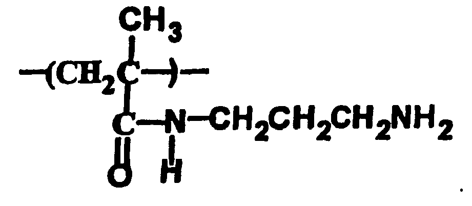
- The method of claim 19, further comprising chill-setting the coating after providing the coating on the medical device.
- The method of claim 19, further comprising using a cross-linker to cross-link the polymer and the first hydrogel to form a hydrogel overcoat.
- The method of claim 19, wherein the polymer is not covalently linked to the medical device.
- The method of claim 19, wherein the paramagnetic-metal-ion is designated as Mn+, and M is a lanthanide or a transition metal which is iron, manganese, chromium, cobalt or nickel, and n is an integer that is 2 or greater.
- The method of claim 24, wherein M is a lanthanide and the lanthanide is gadolinium.
- The method of 19, wherein the chelate is selected from the group consisting of diethylenetriaminepentaacetic acid (DTPA), 1,4,7,10-tetracyclododecane-N,N',N",N"'-tetraacetic acid (DOTA) and 1,4,8,11-tetraazacyclotradecane-N,N',N",N"'-tetraacetic acid (TETA), diethylenetriaminepentaacetic acid-N,N'-bis(methylamide) (DTPA-BMA), diethylenetriaminepentaacetic acid-N,N'-bis(methoxyethylamide) (DTPA-BMEA), s-4-(4-ethoxybenzyl)-3,6,9-tris[(carboxylatomethyl)]-3,6,9-triazaundecanedionic acid (EOB-DTPA), benzyloxypropionictetraacetate (BOPTA), (4R)-4-[bis(carboxymethylamino)]-3,6,9-triazaundecanedionic acid (MS-325), 1,4,7-tris(carboxymethyl)-10-(2'-hydroxypropyl)-1,4,7,10-tetraazacyclododecane (HP-DO3A), and DO3A-butrol.
- The method of claim 19, wherein the first hydrogel is collagen, gelatin, hyaluronate, fibrin, alginate, agarose, chitosan, poly(acrylic acid), poly(acrylamide), poly(2-hydroxyethyl methacrylate), poly(N-isopropylacrylamide), poly(ethylene glycol)/poly(ethylene oxide), poly(ethylene oxide)-block-poly(lactic acid), poly(vinyl alcohol), polyphosphazenes, polypeptides or a combination thereof.
- The method of claim 19, wherein a linker or spacer molecule links the chelate of the paramagnetic-metal-ion/chelate complex to the functional group, and the linker or spacer molecule is lactam or diamine.
- The method of claim 1, wherein the functional group is a functional group of a second hydrogel.
- The method of claim 29, wherein the first hydrogel and the second hydrogel are selected from the group consisting of collagen, gelatin, hyaluronate, fibrin, alginate, agarose, chitosan, poly(acrylic acid), poly(acrylamide), poly(2-hydroxyethyl methacrylate), poly(N-isopropylacrylamide), poly(ethylene glycol)/poly(ethylene oxide), poly(ethylene oxide)-block-poly(lactic acid), poly(vinyl alcohol), a polyphosphazene, a polypeptide and combinations thereof, and wherein the first hydrogel and the second hydrogel are the same or different.
- The method of claim 30, wherein the first hydrogel and second hydrogel are gelatin.
- The method of claim 29, wherein the complex is mixed with the first hydrogel to produce the coating.
- The method of claim 29, further comprising chill-setting the coating after providing the coating thereon.
- The method of claim 29, further comprising using a cross-linker to cross-link the first hydrogel and the second hydrogel to form a hydrogel overcoat.
- The method of claim 34, wherein the cross-linker is glutaraldehyde.
- The method of claim 29, wherein the paramagnetic-metal-ion is designated as Mn+, and M is a lanthanide or a transition metal which is iron, manganese, chromium, cobalt or nickel, and n is an integer that is 2 or greater.
- The method of claim 36, wherein M is a lanthanide and the lanthanide is gadolinium.
- The method of claim 29, wherein the chelate is selected from the group consisting of diethylenetriaminepentaacetic acid (DTPA), 1,4,7,10-tetracyclododecane-N,N',N",N"'-tetraacetic acid (DOTA) and 1,4,8,11-tetraazacyclotradecane-N,N',N'',N'''-tetraacetic acid (TETA), diethylenetriaminepentaacetic acid-N,N'-bis(methylamide) (DTPA-BMA), diethylenetriaminepentaacetic acid-N,N'-bis(methoxyethylamide) (DTPA-BMEA), s-4-(4-ethoxybenzyl)-3,6,9-tris[(carboxylatomethyl)]-3,6,9-triazaundecanedionic acid (EOB-DTPA), benzyloxypropionictetraacetate (BOPTA), (4R)-4-[bis(carboxymethylamino)]-3,6,9-triazaundecanedionic acid (MS-325), 1,4,7-tris(carboxymethyl)-10-(2'-hydroxypropyl)-1,4,7,10-tetraazacyclododecane (HP-DO3A), and DO3A-butrol.
- The method of claim 36, wherein the first hydrogel is gelatin, the second hydrogel is gelatin and the chelate is DTPA.
- The method of claim 29, wherein a linker or spacer molecule links the chelate of the paramagnetic-metal-ion/chelate complex to the functional group, and the linker or spacer molecule is lactam or diamine.
- A medical device capable of being magnetic-resonance imaged, the device comprising:a chelate covalently linked to a functional group, the functional group being an amino or carboxyl group;a paramagnetic-metal-ion coordinated with the chelate to form a paramagnetic-metal-ion/chelate complex; anda first hydrogel encapsulating the paramagnetic-metal-ion/chelate complex.
- The device of claim 41, wherein at least a portion of the medical device is made of a solid-base polymer, and the functional group is a functional on the solid-base polymer, and the paramagnetic-metal-ion/chelate complex is accordingly covalently linked to the medical device.
- The device of claim 42, wherein the functional group on the solid-base polymer is formed by treating the substrate to yield the functional group thereon.
- The device of claim 43, wherein treating the solid-base polymer comprises plasma treating the solid-base polymer with a plasma gas which is carbon dioxide, oxygen, hydrazine, ammonia, a chemical moiety of a nitrogen-hydrogen combination or combinations thereof.
- The device of claim 43, wherein treating the solid-base polymer comprises melt coating with a hydrophilic polymer or precoating with a hydrophilic polymer containing primary amino groups.
- The device of claim 42, wherein the polymer is selected from the group consisting of polyethylenes, polypropylenes, polyesters, polyamides, polytetrafluoroethylene, polyurethanes, polyamino undecanoic acid, polydimethylsiloxane, polyglycols, polyoxyethylenes, polysorbate 60, stearate and palmitate esters of sorbitol copolymerized with ethylene glycol, polyvinyl acetate phthalate, polyvinyl alcohol and polystyrene sulfonate.
- The device of claim 42, wherein the paramagnetic-metal-ion is designated as Mn+, and M is a lanthanide or a transition metal which is iron, manganese, chromium, cobalt or nickel, and n is an integer that is 2 or greater.
- The device of claim 47, wherein M is a lanthanide and the lanthanide is gadolinium.
- The device of claim 42, wherein the chelate is selected from the group consisting of diethylenetriaminepentaacetic acid (DTPA), 1,4,7,10-tetracyclododecane-N,N',N",N"'-tetraacetic acid (DOTA) and 1,4,8,11-tetraazacyclotradecane-N,N',N'',N'''-tetraacetic acid (TETA), diethylenetriaminepentaacetic acid-N,N'-bis(methylamide) (DTPA-BMA), diethylenetriaminepentaacetic acid-N,N'-bis(methoxyethylamide) (DTPA-BMEA), s-4-(4-ethoxybenzyl)-3,6,9-tris[(carboxylatomethyl)]-3,6,9-triazaundecanedionic acid (EOB-DTPA), benzyloxypropionictetraacetate (BOPTA), (4R)-4-[bis(carboxymethylamino)]-3,6,9-triazaundecanedionic acid (MS-325), 1,4,7-tris(carboxymethyl)-10-(2'-hydroxypropyl)-1,4,7,10-tetraazacyclododecane (HP-DO3A), and DO3A-butrol.
- The device of claim 42, wherein the first hydrogel is collagen, gelatin, hyaluronate, fibrin, alginate, agarose, chitosan, poly(acrylic acid), poly(acrylamide), poly(2-hydroxyethyl methacrylate), poly(N-isopropylacrylamide), poly(ethylene glycol)/poly(ethylene oxide), poly(ethylene oxide)-block-poly(lactic acid), poly(vinyl alcohol), polyphosphazenes, polypeptides or a combination thereof.
- The device of claim 42, wherein a linker or spacer molecule links the chelate of the paramagnetic-metal-ion/chelate complex to the functional group, and the linker or spacer molecule is lactam or diamine.
- The device of claim 42, wherein the polymer and the first hydrogel are cross-linked to produce a hydrogel overcoat using a cross-linker.
- The device of claim 52, wherein the cross-linker is glutaraldehyde.
- The device of claim 41, wherein the functional group is a functional group of a polymer.
- The device of claim 54, wherein the polymer has the following repeating structure:
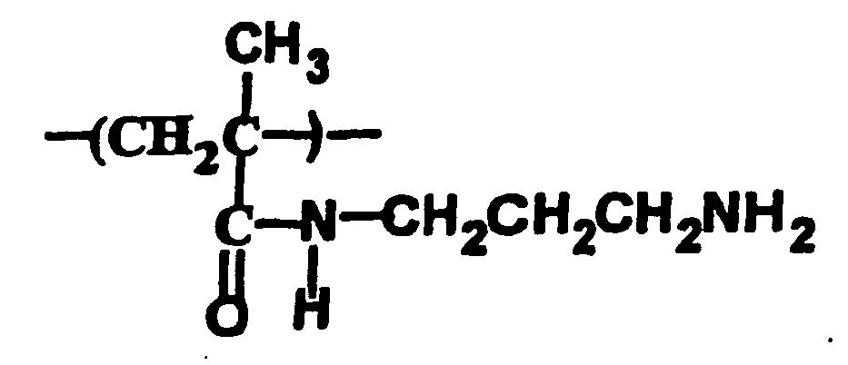
- The device of claim 54, wherein the polymer is not covalently linked to the medical device.
- The device of claim 54, wherein a cross-linker cross-links the polymer and the first hydrogel to produce a hydrogel overcoat.
- The device of claim 57, wherein the cross-linker is glutaraldehyde.
- The device of claim 54, wherein the paramagnetic-metal-ion is designated as Mn+, and M is a lanthanide or a transition metal which is iron, manganese, chromium, cobalt or nickel, and n is an integer that is 2 or greater.
- The device of claim 59, wherein M is a lanthanide and the lanthanide is gadolinium.
- The device of claim 54, wherein the chelate is selected from the group consisting of diethylenetriaminepentaacetic acid (DTPA), 1,4,7,10-tetracyclododecane-N,N',N",N"'-tetraacetic acid (DOTA) and 1,4,8,11-tetraazacyclotradecane-N,N',N",N'''-tetraacetic acid (TETA), diethylenetriaminepentaacetic acid-N,N'-bis(methylamide) (DTPA-BMA), diethylenetriaminepentaacetic acid-N,N'-bis(methoxyethylamide) (DTPA-BMEA), s-4-(4-ethoxybenzyl)-3,6,9-tris[(carboxylatomethyl)]-3,6,9-triazaundecanedionic acid (EOB-DTPA), benzyloxypropionictetraacetate (BOPTA), (4R)-4-[bis(carboxymethylamino)]-3,6,9-triazaundecanedionic acid (MS-325), 1,4,7-tris(carboxymethyl)-10-(2'-hydroxypropyl)-1,4,7,10-tetraazacyclododecane (HP-D03A), and D03A-butrol.
- The device of claim 61, wherein the chelate is a DTPA.
- The device of claim 54, wherein the first hydrogel is collagen, gelatin, hyaluronate, fibrin, alginate, agarose, chitosan, poly(acrylic acid), poly(acrylamide), poly(2-hydroxyethyl methacrylate), poly(N-isopropylacrylamide), poly(ethylene glycol)/poly(ethylene oxide), poly(ethylene oxide)-block-poly(lactic acid), poly(vinyl alcohol), polyphosphazenes, polypeptides or a combination thereof.
- The device of claim 54, wherein a linker or spacer molecule links the paramagnetic-metal-ion/chelate complex to the functional group, and the linker or spacer molecule is lactam or diamine.
- The device of claim 41, wherein the functional group is a functional group of a second hydrogel.
- The device of claim 65, wherein the first hydrogel and the second hydrogel are selected from the group consisting of collagen, gelatin, hyaluronate, fibrin, alginate, agarose, chitosan, poly(acrylic acid), poly(acrylamide), poly(2-hydroxyethyl methacrylate), poly(N-isopropylacrylamide), poly(ethylene glycol)/poly(ethylene oxide), poly(ethylene oxide)-block-poly(lactic acid), poly(vinyl alcohol), a polyphosphazene, a polypeptide and combinations thereof, and wherein the first hydrogel and the second hydrogel are the same or different.
- The device of claim 65, wherein the first hydrogel and second hydrogel are gelatin.
- The device of claim 65, wherein the first hydrogel and the second hydrogel are cross-linked using a cross-linker to form a hydrogel overcoat.
- The device of claim 68, wherein the cross-linker is glutaraldehyde.
- The device of claim 65, wherein the paramagnetic-metal-ion is designated as Mn+, and M is a lanthanide or a transition metal which is iron, manganese, chromium, cobalt or nickel, and n is an integer that is 2 or greater.
- The device of claim 70, wherein M is a lanthanide and the lanthanide is gadolinium.
- The device of claim 65, wherein the chelate is selected from the group consisting of diethylenetriaminepentaacetic acid (DTPA), 1,4,7,10-tetracyclododecane-N,N',N",N"'-tetraacetic acid (DOTA) and 1,4,8,11-tetraazacyclotradecane-N,N',N'',N'''-tetraacetic acid (TETA), diethylenetriaminepentaacetic acid-N,N'-bis(methylamide) (DTPA-BMA), diethylenetriaminepentaacetic acid-N,N'-bis(methoxyethylamide) (DTPA-BMEA), s-4-(4-ethoxybenzyl)-3,6,9-tris[(carboxylatomethyl)]-3,6,9-triazaundecanedionic acid (EOB-DTPA), benzyloxypropionictetraacetate (BOPTA), (4R)-4-[bis(carboxymethylamino)]-3,6,9-triazaundecanedionic acid (MS-325), 1,4,7-tris(carboxymethyl)-10-(2'-hydroxypropyl)-1,4,7,10-tetraazacyclododecane (HP-D03A), and DO3A-butrol.
- The device of claim 65, wherein a linker or spacer molecule links the paramagnetic-metal-ion/chelate complex to the functional group, and the linker or spacer molecule is lactam or diamine.
- A method of reducing the mobility of paramagnetic-metal-ion/chelate complexes covalently linked to a solid-base polymer of a medical device, the method comprising:providing a medical device having paramagnetic-metal-ion/chelate complexes covalently linked to the solid-base polymer of the medical device; andencapsulating at least one of the paramagnetic-metal-ion/chelate complexes covalently linked to the medical device with a hydrogel, the hydrogel reducing the mobility of at least one of the paramagnetic-metal-ion/chelate complexes, and thereby enhancing the magnetic resonance imageability of the medical device.
- The method of claim 74, wherein providing a medical device having paramagnetic-metal-ion/chelate complexes covalently linked to the solid-base polymer of the medical device further comprises plasma treating at least a portion of the solid-base polymer of the medical device before covalently linking the complex thereto, in order to provide functional groups selected from the group consisting of amino groups and carboxyl groups linked thereto.
- The method of claim 75, wherein providing a medical device having paramagnetic-metal-ion/chelate complexes covalently linked to the solid-base polymer of the medical device further comprises covalently linking the paramagnetic-metal-ion/chelate complexes to the functional groups.
- The method of claims 76, wherein a linker or a spacer molecule links the paramagnetic-metal-ion/chelate complexes to the functional groups, and the linker or spacer molecule is lactam or diamine.
- The method of claim 74, wherein the hydrogel is collagen, gelatin, hyaluronate, fibrin, alginate, agarose, chitosan, poly(acrylic acid), poly(acrylamide), poly(2-hydroxyethyl methacrylate), poly(N-isopropylacrylamide), poly(ethylene glycol)/poly(ethylene oxide), poly(ethylene oxide)-block-poly(lactic acid), poly(vinyl alcohol), polyphosphazenes, polypeptides or a combination thereof.
- The method of claim 74, wherein the polymer is selected from the group consisting of polyethylenes, polypropylenes, polyesters, polyamides, polytetrafluoroethylene, polyurethanes, polyamino undecanoic acid, polydimethylsiloxane, polyglycols, polyoxyethylenes, polysorbate 60, stearate and palmitate esters of sorbitol copolymerized with ethylene glycol, polyvinyl acetate phthalate, polyvinyl alcohol and polystyrene sulfonate.
- The method of claim 74, wherein the paramagnetic-metal-ion is designated as Mn+, and M is a lanthanide or a transition metal which is iron, manganese, chromium, cobalt or nickel, and N is an integer that is 2 or greater.
- The method of claim 80, wherein M is a lanthanide and the lanthanide is gadolinium.
- The method of claim 74, wherein the chelate is selected from the group consisting of diethylenetriaminepentaacetic acid (DTPA), 1,4,7,10-tetracyclododecane-N,N',N",N"'-tetraacetic acid (DOTA) and 1,4,8,11-tetraazacyclotradecane-N,N',N'',N'''-tetraacetic acid (TETA), diethylenetriaminepentaacetic acid-N,N'-bis(methylamide) (DTPA-BMA), diethylenetriaminepentaacetic acid-N,N'-bis(methoxyethylamide) (DTPA-BMEA), s-4-(4-ethoxybenzyl)-3,6,9-tris[(carboxylatomethyl)]-3,6,9-triazaundecanedionic acid (EOB-DTPA), benzyloxypropionictetraacetate (BOPTA), (4R)-4-[bis(carboxymethylamino)]-3,6,9-triazaundecanedionic acid (MS-325), 1,4,7-tris(carboxymethyl)-10-(2'-hydroxypropyl)-1,4,7,10-tetraazacyclododecane (HP-D03A), and DO3A-butrol.
Priority Applications (1)
| Application Number | Priority Date | Filing Date | Title |
|---|---|---|---|
| EP06021362A EP1785146A3 (en) | 2002-05-09 | 2002-12-13 | Mr-signal emitting coatings |
Applications Claiming Priority (3)
| Application Number | Priority Date | Filing Date | Title |
|---|---|---|---|
| US10/142,363 US6896874B2 (en) | 1998-05-26 | 2002-05-09 | MR-signal emitting coatings |
| US142363 | 2002-05-09 | ||
| PCT/US2002/040007 WO2003094975A1 (en) | 2002-05-09 | 2002-12-13 | Mr-signal emitting coatings |
Related Child Applications (1)
| Application Number | Title | Priority Date | Filing Date |
|---|---|---|---|
| EP06021362A Division EP1785146A3 (en) | 2002-05-09 | 2002-12-13 | Mr-signal emitting coatings |
Publications (2)
| Publication Number | Publication Date |
|---|---|
| EP1501552A1 EP1501552A1 (en) | 2005-02-02 |
| EP1501552B1 true EP1501552B1 (en) | 2008-05-28 |
Family
ID=29418428
Family Applications (2)
| Application Number | Title | Priority Date | Filing Date |
|---|---|---|---|
| EP06021362A Withdrawn EP1785146A3 (en) | 2002-05-09 | 2002-12-13 | Mr-signal emitting coatings |
| EP02790131A Expired - Lifetime EP1501552B1 (en) | 2002-05-09 | 2002-12-13 | Mr-signal emitting coatings |
Family Applications Before (1)
| Application Number | Title | Priority Date | Filing Date |
|---|---|---|---|
| EP06021362A Withdrawn EP1785146A3 (en) | 2002-05-09 | 2002-12-13 | Mr-signal emitting coatings |
Country Status (7)
| Country | Link |
|---|---|
| US (1) | US6896874B2 (en) |
| EP (2) | EP1785146A3 (en) |
| JP (1) | JP4455320B2 (en) |
| AU (1) | AU2002353152A1 (en) |
| CA (1) | CA2485291A1 (en) |
| DE (1) | DE60226901D1 (en) |
| WO (1) | WO2003094975A1 (en) |
Families Citing this family (33)
| Publication number | Priority date | Publication date | Assignee | Title |
|---|---|---|---|---|
| US7632651B2 (en) | 1997-09-15 | 2009-12-15 | Mds Analytical Technologies (Us) Inc. | Molecular modification assays |
| EP1360638A1 (en) * | 2001-02-09 | 2003-11-12 | Enseal Systems Limited | Document printed with graphical symbols which encode information |
| US20040143180A1 (en) * | 2001-11-27 | 2004-07-22 | Sheng-Ping Zhong | Medical devices visible under magnetic resonance imaging |
| US20030100830A1 (en) * | 2001-11-27 | 2003-05-29 | Sheng-Ping Zhong | Implantable or insertable medical devices visible under magnetic resonance imaging |
| US20040253292A1 (en) * | 2003-04-23 | 2004-12-16 | Wisconsin Alumni Research Foundation | MR-signal emitting coatings |
| CN100528076C (en) * | 2003-12-08 | 2009-08-19 | 西门子公司 | Water-soluble paramagnetic substance for reducing the relaxation time of a coolant and corresponding method |
| WO2005065724A1 (en) * | 2003-12-30 | 2005-07-21 | Alnis Biosciences, Inc. | Formulations of paramagnetic ion complexes |
| US8620406B2 (en) * | 2004-01-23 | 2013-12-31 | Boston Scientific Scimed, Inc. | Medical devices visible by magnetic resonance imaging |
| US7761138B2 (en) * | 2004-03-12 | 2010-07-20 | Boston Scientific Scimed, Inc. | MRI and X-ray visualization |
| WO2006039505A2 (en) | 2004-09-30 | 2006-04-13 | Molecular Devices Corporation | Luminescent lanthanide complexes |
| US7778684B2 (en) * | 2005-08-08 | 2010-08-17 | Boston Scientific Scimed, Inc. | MRI resonator system with stent implant |
| US20070156042A1 (en) * | 2005-12-30 | 2007-07-05 | Orhan Unal | Medical device system and method for tracking and visualizing a medical device system under MR guidance |
| US8457712B2 (en) | 2005-12-30 | 2013-06-04 | Wisconsin Alumni Research Foundation | Multi-mode medical device system and methods of manufacturing and using same |
| US20070239256A1 (en) * | 2006-03-22 | 2007-10-11 | Jan Weber | Medical devices having electrical circuits with multilayer regions |
| US20080091530A1 (en) | 2006-04-28 | 2008-04-17 | Rockne Egnatios | Methods and systems for providing cross-selling with online banking environments |
| US20090142273A1 (en) * | 2006-06-08 | 2009-06-04 | Case Western Reserve University | Activatable cest MRI agent |
| JP5552690B2 (en) | 2006-09-13 | 2014-07-16 | ディーエスエム アイピー アセッツ ビー.ブイ. | Coated medical device |
| WO2008035759A1 (en) | 2006-09-22 | 2008-03-27 | Terumo Kabushiki Kaisha | Polymer having visibility in magnetic resonance image and surface lubricity and medical device |
| US8532742B2 (en) * | 2006-11-15 | 2013-09-10 | Wisconsin Alumni Research Foundation | System and method for simultaneous 3DPR device tracking and imaging under MR-guidance for therapeutic endovascular interventions |
| US20080183070A1 (en) * | 2007-01-29 | 2008-07-31 | Wisconsin Alumni Research Foundation | Multi-mode medical device system with thermal ablation capability and methods of using same |
| US8412306B2 (en) * | 2007-02-28 | 2013-04-02 | Wisconsin Alumni Research Foundation | Voltage standing wave suppression for MR-guided therapeutic interventions |
| US20080272776A1 (en) * | 2007-05-03 | 2008-11-06 | Edelman Robert R | Magnetic resonance image acquisition with suppression of background tissues and rf water excitation at offset frequency |
| US20100201361A1 (en) * | 2007-05-03 | 2010-08-12 | Edelman Robert R | System and method for passive catheter tracking with magnetic resonance imaging |
| WO2008141612A2 (en) * | 2007-05-22 | 2008-11-27 | Feg Textiltechnik Forschungs- Und Entwicklungsgesellschaft Mbh | Implant |
| CN106913902A (en) | 2009-11-09 | 2017-07-04 | 聚光灯技术合伙有限责任公司 | Polysaccharide based aquagel |
| CN102695501A (en) | 2009-11-09 | 2012-09-26 | 聚光灯技术合伙有限责任公司 | Fragmented hydrogels |
| WO2011074499A1 (en) * | 2009-12-15 | 2011-06-23 | テルモ株式会社 | Medical device and method for producing same |
| EP2450067A1 (en) | 2010-10-18 | 2012-05-09 | MaRVis Technologies GmbH | Medical device |
| EP2484388A1 (en) * | 2011-02-05 | 2012-08-08 | MaRVis Technologies GmbH | Implantable or insertable MRI-detectable medical device having a coating comprising paramagnetic ions and a process for preparing it |
| EP2692365A1 (en) * | 2012-08-03 | 2014-02-05 | MaRVis Medical GmbH | Implantable or insertable MRI-detectable medical device having a coating comprising paramagnetic ions and a process for preparing it |
| DE102014005994A1 (en) | 2014-04-23 | 2015-10-29 | Marvis Medical Gmbh | Rod-shaped body and medical instrument |
| US10501575B2 (en) * | 2015-05-26 | 2019-12-10 | The Board Of Regents Of The University Of Texas System | Biomimetic fluoroscopic films |
| CN110746614A (en) * | 2018-07-24 | 2020-02-04 | 西安交通大学 | A kind of preparation method of impact-resistant high-strength physical hydrogel and application thereof |
Family Cites Families (27)
| Publication number | Priority date | Publication date | Assignee | Title |
|---|---|---|---|---|
| SE465907B (en) | 1984-11-01 | 1991-11-18 | Nyegaard & Co As | DIAGNOSTIC AGENT CONTENT AND PARAMAGNETIC METAL |
| AU593611B2 (en) | 1986-02-14 | 1990-02-15 | Nihon Medi-Physics Co., Ltd. | High molecular compounds having amino groups, and their utilization |
| US5039512A (en) | 1986-08-04 | 1991-08-13 | Salutar, Inc. | NMR imaging with paramagnetic polyvalent metal salts of poly-(acid-alkylene-amino)-alkanes |
| DE3640708C2 (en) | 1986-11-28 | 1995-05-18 | Schering Ag | Improved pharmaceuticals containing metals |
| DE3806795A1 (en) | 1988-02-29 | 1989-09-07 | Schering Ag | POLYMER-TIED COMPLEX IMAGERS, THEIR COMPLEXES AND CONJUGATES, METHOD FOR THEIR PRODUCTION AND PHARMACEUTICAL AGENTS CONTAINING THEM |
| US5627079A (en) | 1989-03-27 | 1997-05-06 | The Research Foundation Of State University Of New York | Refunctionalized oxyfluorinated surfaces |
| US5087440A (en) | 1989-07-31 | 1992-02-11 | Salutar, Inc. | Heterocyclic derivatives of DTPA used for magnetic resonance imaging |
| WO1992000748A1 (en) | 1990-07-06 | 1992-01-23 | Enzon, Inc. | Poly(alkylene oxide) amino acid copolymers and drug carriers and charged copolymers based thereon |
| EP0508345A3 (en) | 1991-04-09 | 1994-06-01 | Hoechst Ag | Volatile alkaline earth complex and its application |
| WO1994009056A1 (en) | 1992-10-14 | 1994-04-28 | Sterling Winthrop Inc. | Chelating polymers |
| US5817292A (en) | 1992-10-14 | 1998-10-06 | Nycomed Imaging As | MR imaging compositions and methods |
| ES2140469T3 (en) | 1992-10-14 | 2000-03-01 | Nycomed Imaging As | COMPOSITIONS AND THERAPEUTIC AND DIAGNOSTIC METHODS FOR OBTAINING IMAGES. |
| US5756688A (en) | 1992-10-14 | 1998-05-26 | Sterling Winthrop Inc. | MR imaging compositions and methods |
| ATE195258T1 (en) | 1993-04-14 | 2000-08-15 | Pharmacyclics Inc | MEDICAL DEVICES AND MATERIALS WITH INCREASED VISIBILITY DURING MAGNETIC IMAGING |
| DE69332120T2 (en) | 1993-08-12 | 2003-02-27 | Advanced Magnetics, Inc. | USE OF SUPERPARAMAGNETIC OXIDE COLLOIDS COVERED WITH POLYSACCHARIDES |
| GB9404208D0 (en) | 1994-03-04 | 1994-04-20 | Nycomed Salutar Inc | Chelants |
| US5958372A (en) | 1994-06-28 | 1999-09-28 | Nycomed Imaging As | Low viscosity chelating polymers for diagnostic imaging |
| US5980862A (en) * | 1995-06-02 | 1999-11-09 | Research Corporation Technologies | Magnetic resonance imaging agents for the detection of physiological agents |
| US5744958A (en) | 1995-11-07 | 1998-04-28 | Iti Medical Technologies, Inc. | Instrument having ultra-thin conductive coating and method for magnetic resonance imaging of such instrument |
| JP4432000B2 (en) | 1996-12-23 | 2010-03-17 | ブラッコ・リサーチ・ソシエテ・アノニム | Composition for increasing MRI contrast in visualization of a patient's gastrointestinal tract |
| US6361759B1 (en) | 1998-05-26 | 2002-03-26 | Wisconsin Alumni Research Foundation | MR signal-emitting coatings |
| US6395299B1 (en) * | 1999-02-12 | 2002-05-28 | Biostream, Inc. | Matrices for drug delivery and methods for making and using the same |
| JP3344371B2 (en) | 1999-06-23 | 2002-11-11 | トヨタ自動車株式会社 | Exhaust gas purification device for internal combustion engine |
| FR2808026B1 (en) | 2000-04-25 | 2002-06-14 | Alexandre Laurent | BIOMATERIAL BASED ON HYDROPHILIC POLYMER HAVING A SPECIFIC SIGNAL IN MAGNETIC RESONANCE IMAGING AND METHOD FOR PREPARING SUCH A BIOMATERIAL |
| KR100756801B1 (en) | 2000-09-11 | 2007-09-07 | 유니온 카바이드 케미칼즈 앤드 플라스틱스 테크날러지 코포레이션 | Hydrophilic Lubricating Medical Device with Contrast to Magnetic Resonance Imaging |
| US20030100830A1 (en) * | 2001-11-27 | 2003-05-29 | Sheng-Ping Zhong | Implantable or insertable medical devices visible under magnetic resonance imaging |
| WO2007063585A1 (en) | 2005-11-30 | 2007-06-07 | Fujitsu Limited | Communication device and frame control method |
-
2002
- 2002-05-09 US US10/142,363 patent/US6896874B2/en not_active Expired - Lifetime
- 2002-12-13 EP EP06021362A patent/EP1785146A3/en not_active Withdrawn
- 2002-12-13 JP JP2004503058A patent/JP4455320B2/en not_active Expired - Fee Related
- 2002-12-13 WO PCT/US2002/040007 patent/WO2003094975A1/en not_active Ceased
- 2002-12-13 DE DE60226901T patent/DE60226901D1/en not_active Expired - Lifetime
- 2002-12-13 CA CA002485291A patent/CA2485291A1/en not_active Abandoned
- 2002-12-13 AU AU2002353152A patent/AU2002353152A1/en not_active Abandoned
- 2002-12-13 EP EP02790131A patent/EP1501552B1/en not_active Expired - Lifetime
Also Published As
| Publication number | Publication date |
|---|---|
| JP4455320B2 (en) | 2010-04-21 |
| EP1785146A2 (en) | 2007-05-16 |
| EP1785146A3 (en) | 2007-07-18 |
| US6896874B2 (en) | 2005-05-24 |
| DE60226901D1 (en) | 2008-07-10 |
| US20030099764A1 (en) | 2003-05-29 |
| EP1501552A1 (en) | 2005-02-02 |
| CA2485291A1 (en) | 2003-11-20 |
| JP2005525176A (en) | 2005-08-25 |
| AU2002353152A1 (en) | 2003-11-11 |
| WO2003094975A1 (en) | 2003-11-20 |
Similar Documents
| Publication | Publication Date | Title |
|---|---|---|
| EP1501552B1 (en) | Mr-signal emitting coatings | |
| AU758331B2 (en) | MR signal-emitting coatings | |
| US8412306B2 (en) | Voltage standing wave suppression for MR-guided therapeutic interventions | |
| US8532742B2 (en) | System and method for simultaneous 3DPR device tracking and imaging under MR-guidance for therapeutic endovascular interventions | |
| US8457712B2 (en) | Multi-mode medical device system and methods of manufacturing and using same | |
| US20080183070A1 (en) | Multi-mode medical device system with thermal ablation capability and methods of using same | |
| US20070156042A1 (en) | Medical device system and method for tracking and visualizing a medical device system under MR guidance | |
| CA2471958C (en) | Implantable or insertable medical devices visible under magnetic resonance imaging | |
| US20040253292A1 (en) | MR-signal emitting coatings | |
| MXPA00011564A (en) | Mr signal-emitting coatings | |
| CN1318094C (en) | Magnetic resonance radiography reinforcing coating composition used for interposing catheter or device and its preparation method |
Legal Events
| Date | Code | Title | Description |
|---|---|---|---|
| PUAI | Public reference made under article 153(3) epc to a published international application that has entered the european phase |
Free format text: ORIGINAL CODE: 0009012 |
|
| 17P | Request for examination filed |
Effective date: 20041109 |
|
| AK | Designated contracting states |
Kind code of ref document: A1 Designated state(s): AT BE BG CH CY CZ DE DK EE ES FI FR GB GR IE IT LI LU MC NL PT SE SI SK TR |
|
| AX | Request for extension of the european patent |
Extension state: AL LT LV MK RO |
|
| RIN1 | Information on inventor provided before grant (corrected) |
Inventor name: UNAL, ORHAN Inventor name: LI, JUNWEI Inventor name: STROTHER, CHARLES, MILTON Inventor name: YU, HYUK Inventor name: JIANG, XIQUN |
|
| DAX | Request for extension of the european patent (deleted) | ||
| RBV | Designated contracting states (corrected) |
Designated state(s): DE FR GB IT |
|
| 17Q | First examination report despatched |
Effective date: 20050718 |
|
| 17Q | First examination report despatched |
Effective date: 20050718 |
|
| GRAP | Despatch of communication of intention to grant a patent |
Free format text: ORIGINAL CODE: EPIDOSNIGR1 |
|
| GRAS | Grant fee paid |
Free format text: ORIGINAL CODE: EPIDOSNIGR3 |
|
| GRAA | (expected) grant |
Free format text: ORIGINAL CODE: 0009210 |
|
| AK | Designated contracting states |
Kind code of ref document: B1 Designated state(s): DE FR GB IT |
|
| REG | Reference to a national code |
Ref country code: GB Ref legal event code: FG4D |
|
| REF | Corresponds to: |
Ref document number: 60226901 Country of ref document: DE Date of ref document: 20080710 Kind code of ref document: P |
|
| PLBI | Opposition filed |
Free format text: ORIGINAL CODE: 0009260 |
|
| 26 | Opposition filed |
Opponent name: MARVIS TECHNOLOGIES GMBH Effective date: 20090302 |
|
| PLAX | Notice of opposition and request to file observation + time limit sent |
Free format text: ORIGINAL CODE: EPIDOSNOBS2 |
|
| PLAF | Information modified related to communication of a notice of opposition and request to file observations + time limit |
Free format text: ORIGINAL CODE: EPIDOSCOBS2 |
|
| PLBB | Reply of patent proprietor to notice(s) of opposition received |
Free format text: ORIGINAL CODE: EPIDOSNOBS3 |
|
| PLAB | Opposition data, opponent's data or that of the opponent's representative modified |
Free format text: ORIGINAL CODE: 0009299OPPO |
|
| PGFP | Annual fee paid to national office [announced via postgrant information from national office to epo] |
Ref country code: FR Payment date: 20101224 Year of fee payment: 9 |
|
| R26 | Opposition filed (corrected) |
Opponent name: MARVIS TECHNOLOGIES + KLAUS DUERING Effective date: 20090302 |
|
| PGFP | Annual fee paid to national office [announced via postgrant information from national office to epo] |
Ref country code: GB Payment date: 20101208 Year of fee payment: 9 Ref country code: IT Payment date: 20101218 Year of fee payment: 9 |
|
| PGFP | Annual fee paid to national office [announced via postgrant information from national office to epo] |
Ref country code: DE Payment date: 20101208 Year of fee payment: 9 |
|
| PLCK | Communication despatched that opposition was rejected |
Free format text: ORIGINAL CODE: EPIDOSNREJ1 |
|
| REG | Reference to a national code |
Ref country code: DE Ref legal event code: R100 Ref document number: 60226901 Country of ref document: DE |
|
| PLBN | Opposition rejected |
Free format text: ORIGINAL CODE: 0009273 |
|
| STAA | Information on the status of an ep patent application or granted ep patent |
Free format text: STATUS: OPPOSITION REJECTED |
|
| 27O | Opposition rejected |
Effective date: 20120109 |
|
| REG | Reference to a national code |
Ref country code: DE Ref legal event code: R100 Ref document number: 60226901 Country of ref document: DE Effective date: 20120109 |
|
| GBPC | Gb: european patent ceased through non-payment of renewal fee |
Effective date: 20111213 |
|
| REG | Reference to a national code |
Ref country code: FR Ref legal event code: ST Effective date: 20120831 |
|
| REG | Reference to a national code |
Ref country code: DE Ref legal event code: R119 Ref document number: 60226901 Country of ref document: DE Effective date: 20120703 |
|
| PG25 | Lapsed in a contracting state [announced via postgrant information from national office to epo] |
Ref country code: GB Free format text: LAPSE BECAUSE OF NON-PAYMENT OF DUE FEES Effective date: 20111213 Ref country code: DE Free format text: LAPSE BECAUSE OF NON-PAYMENT OF DUE FEES Effective date: 20120703 |
|
| PG25 | Lapsed in a contracting state [announced via postgrant information from national office to epo] |
Ref country code: IT Free format text: LAPSE BECAUSE OF NON-PAYMENT OF DUE FEES Effective date: 20111213 |
|
| PG25 | Lapsed in a contracting state [announced via postgrant information from national office to epo] |
Ref country code: FR Free format text: LAPSE BECAUSE OF NON-PAYMENT OF DUE FEES Effective date: 20120102 |