EP1501447B1 - A polymeric stent useful for the treatment of the salivary gland ducts - Google Patents
A polymeric stent useful for the treatment of the salivary gland ducts Download PDFInfo
- Publication number
- EP1501447B1 EP1501447B1 EP02807031A EP02807031A EP1501447B1 EP 1501447 B1 EP1501447 B1 EP 1501447B1 EP 02807031 A EP02807031 A EP 02807031A EP 02807031 A EP02807031 A EP 02807031A EP 1501447 B1 EP1501447 B1 EP 1501447B1
- Authority
- EP
- European Patent Office
- Prior art keywords
- stent
- polymeric
- polymeric stent
- stent according
- funnel
- Prior art date
- Legal status (The legal status is an assumption and is not a legal conclusion. Google has not performed a legal analysis and makes no representation as to the accuracy of the status listed.)
- Expired - Lifetime
Links
Images

Classifications
-
- A—HUMAN NECESSITIES
- A61—MEDICAL OR VETERINARY SCIENCE; HYGIENE
- A61F—FILTERS IMPLANTABLE INTO BLOOD VESSELS; PROSTHESES; DEVICES PROVIDING PATENCY TO, OR PREVENTING COLLAPSING OF, TUBULAR STRUCTURES OF THE BODY, e.g. STENTS; ORTHOPAEDIC, NURSING OR CONTRACEPTIVE DEVICES; FOMENTATION; TREATMENT OR PROTECTION OF EYES OR EARS; BANDAGES, DRESSINGS OR ABSORBENT PADS; FIRST-AID KITS
- A61F2/00—Filters implantable into blood vessels; Prostheses, i.e. artificial substitutes or replacements for parts of the body; Appliances for connecting them with the body; Devices providing patency to, or preventing collapsing of, tubular structures of the body, e.g. stents
- A61F2/02—Prostheses implantable into the body
- A61F2/04—Hollow or tubular parts of organs, e.g. bladders, tracheae, bronchi or bile ducts
- A61F2/06—Blood vessels
-
- A—HUMAN NECESSITIES
- A61—MEDICAL OR VETERINARY SCIENCE; HYGIENE
- A61F—FILTERS IMPLANTABLE INTO BLOOD VESSELS; PROSTHESES; DEVICES PROVIDING PATENCY TO, OR PREVENTING COLLAPSING OF, TUBULAR STRUCTURES OF THE BODY, e.g. STENTS; ORTHOPAEDIC, NURSING OR CONTRACEPTIVE DEVICES; FOMENTATION; TREATMENT OR PROTECTION OF EYES OR EARS; BANDAGES, DRESSINGS OR ABSORBENT PADS; FIRST-AID KITS
- A61F2210/00—Particular material properties of prostheses classified in groups A61F2/00 - A61F2/26 or A61F2/82 or A61F9/00 or A61F11/00 or subgroups thereof
- A61F2210/0004—Particular material properties of prostheses classified in groups A61F2/00 - A61F2/26 or A61F2/82 or A61F9/00 or A61F11/00 or subgroups thereof bioabsorbable
-
- A—HUMAN NECESSITIES
- A61—MEDICAL OR VETERINARY SCIENCE; HYGIENE
- A61F—FILTERS IMPLANTABLE INTO BLOOD VESSELS; PROSTHESES; DEVICES PROVIDING PATENCY TO, OR PREVENTING COLLAPSING OF, TUBULAR STRUCTURES OF THE BODY, e.g. STENTS; ORTHOPAEDIC, NURSING OR CONTRACEPTIVE DEVICES; FOMENTATION; TREATMENT OR PROTECTION OF EYES OR EARS; BANDAGES, DRESSINGS OR ABSORBENT PADS; FIRST-AID KITS
- A61F2250/00—Special features of prostheses classified in groups A61F2/00 - A61F2/26 or A61F2/82 or A61F9/00 or A61F11/00 or subgroups thereof
- A61F2250/0014—Special features of prostheses classified in groups A61F2/00 - A61F2/26 or A61F2/82 or A61F9/00 or A61F11/00 or subgroups thereof having different values of a given property or geometrical feature, e.g. mechanical property or material property, at different locations within the same prosthesis
- A61F2250/0039—Special features of prostheses classified in groups A61F2/00 - A61F2/26 or A61F2/82 or A61F9/00 or A61F11/00 or subgroups thereof having different values of a given property or geometrical feature, e.g. mechanical property or material property, at different locations within the same prosthesis differing in diameter
Definitions
- the present invention relates to a medical device especially useful for surgical endoscopy and treatment of the salivary gland ducts. More specifically, the present invention relates to a stent-like a polymeric device comprising an elastic elongated tube; a funnel attached to said tube, comprising at least one gorge; and at least one flap, having means to anchor said stent to the salivary gland duct to be treated.
- Abnormalities and pathologies of the salivary glands are traditionally divided into four categories: (i) inflammations; (ii) infections, and ( iii ) obstruction to the flow of saliva and (iv) tumors.
- This obstruction is most commonly from the submandibular parotid and glands, usually due to stone formation and due to the presence of strictures and kinks in the salivary gland ducts.
- a polyethylene tube, made of a commercially available intravenous catheter (inner diameter of 1.7 to 2.0 mm, length 45 mm) was implanted by Nahelieli et al. (see Nahlieli et al., J. Oral Maxillofac.
- GB 1,518,654 discloses an endo-oesophageal tube comprising a tubular main part having at or towards one end a resiliently deformable formation which opposes reverse movement of the tubular part after insertion through a stricture, the tubular main part and the formation each being provided with a radioopaque marking.
- the tubular main part may be provided with a flexible funnel at its upper end, and a helical reinforcing element of pylon thread or wire may be embedded in the tubular wall.
- the present invention provides a polymeric stent, especially useful in surgical endoscopy and for the treatment of salivary gland ducts comprising; an elongated tube, wherein the proximal end of said tube has a funnel-like shape; and wherein said funnel further comprises at least one gorge, which enables the suturing of said stent to said duct.
- a polymeric stent as defined above having means to be at least temporally anchored inside the lumen of a salivary duct.
- said means to expand said stent inside the lumen of the salivary gland duct is at least one wing-like flap and/or said stent comprising two wing-like flaps.
- a polymeric stent as defined above adapted to be at least temporally anchored inside the lumen of a salivary duct, wherein the tube additionally comprises at least one extended portion on its width.
- the extended portion is an accordion-like member, as described in Figure 2A , and/or a polymeric stent as defined above, additionally comprising a plurality of flaps, arranged in a circular array of folded flaps, as described in Figure 2C .
- a polymeric stent as defined above in the length of approximately 20 to 65 mm and most particularly in the range of 32 to 48 mm.
- a polymeric stent as defined above, wherein the internal diameter of the elongated tube is in the range of approximately 1.0 to 4.5 mm and most particularly in the range of approximately 1.5 to 3.0 mm.
- a polymeric stent as defined above wherein the length of the funnel-like member is in the range of approximately 1.0 to 4.5 mm and most particularly in the range of approximately 1.0 to 4.5 mm.
- a polymeric stent as defined above wherein the tube is selected from a porousive or a non-porousive article, made by the method selected from knitting or weaving a polymeric sleeve; extruding, cast-forming or press-molding a polymeric raw-material.
- a polymeric stent as defined above is provided, suitable for either local or systemic delivery of compounds selected from drugs and other substances.
- a polymeric stent as defined above wherein the drug to be delivered is selected from one or more biocides, steroidal anti-inflammatory agents, antiviral compound, analgesics, local anesthetics, anticoagulants, antihypertensive substances, vitamins and contrast media.
- said biocide to be delivered is selected from cetylpyridinium chloride, benzalkonium chloride, chlorhexidine, cetyltrimethylammonium bromide, polyoxyethylene, nonylphenols, alkylaryl sulfonates, miconazole nitrate, metronidazole, trimethoprim, chloramphenicol, sulfamethoxazole; cetramide or any effective antibiotic.
- the steroidal anti-inflammatory agents to be delivered are selected from corticosteroids and any hydrocortisone containing compositions.
- said local anesthetic is preferably selected from lidocaine, adrenaline, ephedrine, epinephrine, aminophylline, and theophylline.
- a polymeric stent as defined above having means to be temporally anchored to said stent inside the lumen of the salivary gland duct to be treated, comprising a funnel with two gorges.
- said stent is the one described in figure 2 .
- a method for implanting the polymeric stent into the lumen of a salivary gland duct as defined above comprising; (a) inserting said stent into a salivary gland duct to be treated, such that the whole tube is located in said duct and such that the proximal side of said stent is located inside the oral cavity; and (b) suturing said stent to the mucosa and/or the periosteum near the lingual side of the anterior teeth by means of sutures, wherein said sutures are sutured to at least one gorge located in the funnel.
- a suitable guidance member may alternatively provide said method.
- a method for implanting the polymeric stent into the lumen of a salivary gland duct as defined above is provided, wherein the implanting the polymeric stent into the lumen of a salivary gland duct as above, is aided with a relatively rigid guidance member.
- Said method comprising mainly the hereto define steps of: (a) inserting an effective portion of said guidance member into the tube of the stent at its proximal end; (b) inserting said stent into a salivary gland duct to be treated, such that all of the tube is located in said duct and such that the proximal side of said stent is located inside the oral cavity; (c) removing said guidance member from the stent; and (d) suturing said stent to the mucosa and/or the periosteum near the lingual side of the anterior teeth by means of sutures, wherein said sutures are sutured to at least one gorge located in the funnel.
- the current invention contemplates the usage of any prosthesis, which can be inserted into the saliva duct in order to create a continuous passageway through said duct.
- stent When “stent” is referred to herein, it may include the classical definition of stents as they are used in known intravascular applications. “Stent” used herein also includes any prosthesis which may be inserted and held where desired in the lumen of said saliva duct.
- polymeric compounds that are known to be bioabsorbable and to have the ability to be drug impregnated. These compounds include, yet not limited to poly-1-lactic acid, polyglycolic acid, polyanhydride, and polyphosphate ester, polyurethanes, polyethylene.
- theromplastic polyurethanes such as the commercially available Estane products (such as Estane 58092), are suitable as raw-martials for the hereto-defined stent.
- Estane 58092 are suitable as raw-martials for the hereto-defined stent.
- various coloring materials and surface coatings are suitable for use. Those raw materials may be used in their many forms, i.e., crystals, fibers, blocks, plates, etc. and in a wide range of molecular weights.
- Co-polymers and blends are applicable according to the present invention to form either porous or non-porous polymeric stents.
- the polymeric stents may be made as an extruded open-bore polymeric pipe, a woven or knitted sleeve etc. According to a preferred embodiment of the present invention, extrusion, cast-forming or press-molding techniques are suitable for the production of the polymeric stent.
- said polymeric composition of the stent may be bio-stable or bio-absorbable. If bio-stable, a drug, as wildly defined in the present invention, would diffuse out of the polymer.
- Various compositions are suitable to be delivered either locally or systematically by the aforementioned polymeric stent. These release compositions are selected for drugs, and any other desired materials, including, yet not limited to one or more biocides, steroidal anti-inflammatory agents, antiviral compound, analgesics, local anesthetics, anticoagulants, antihypertensive substances, vitamins and contrast media.
- steroidal anti-inflammatory agents comprising, but not limited to, corticosteroids such as hydrocortisone, hydroxyltriamcinolone, alpha-methyl dexamethasone, dexamethasone-phosphate, beclomethasone dipropionates, clobetasol valerate, desonide, desoxymethasone, desoxycorticosterone acetate, dexamethasone, dichlorisone, diflorasone diacetate, diflucortolone valerate, fluadrenolone, fluclorolone acetonide, fludrocortisone, flumethasone pivalate, fluosinolone acetonide, fluocinonide, flucortine butylesters, fluocortolone, fluprednidene (fluprednylidene) acetate, flurandrenolone, halcinonide, hydrocortisone
- corticosteroids such as hydrocortis
- At least two antiviral compounds may be used, comprising, but not limited to acyclovir and interferon.
- steroidal analgesics comprising, but not limited to aspirin, salicylic acid, diflunisal, morphine and its salts and the like.
- antiseptic substances comprising, but not limited to cetylpyridinium chloride, benzalkonium chloride, chlorhexidine and the like.
- antimycotic substances comprising, but not limited to cetyltrimethylammonium bromide and the like.
- antifungals comprising, but not limited to polyoxyethylene nonylphenols, alkylaryl sulfonates, miconazole nitrate, metronidazole, trimethoprim and the like.
- antiprotozoals may be used, comprising, but not limited to chloramphenicol, sulfamethoxazole and the like.
- local anesthetics comprising, but not limited to salts of procaine, benzocaine, lidocain, procain, bupivacaine, tetracain, xylocaine, mepivacaine and their salts and the like; antiasthma drugs such as adrenaline, ephedrine, epinephrine, aminophylline, theophylline and the like.
- antihypertensive comprising, but not limited to methyldopa, hydralazine, clonidine, chlorothiazide, timolol, propanolol, metroprolol, prazosin hydrochloride, furosemide and the like.
- vitamins may be used, comprising, but not limited to such as B 6 , B 12 and C and the like.
- contrast media comprising, but not limited to BaSO 4 , iohexol and other iodine-containing substances and the like (x-ray), iron(II,III)oxide particles, titanium dioxide pigments, and other ferromagnetic materials (magnetic resonance imaging). It is acknowledged in this respect, that various coloring materials, such as 14-4007 PV fast violet pigments, are possible ingredients of the material forming or coating the stents.
- Said stent comprises an elongated open-bore polymeric tube (1), comprising a proximal rim (i) located adjacent to the oral cavity when implanted in the salivary gland duct, and a distal rim (ii), located adjacent to the salivary gland when implanted in the salivary gland duct.
- the aforementioned stent additionally comprises a funnel (2), located in the proximal rim of said tube.
- the inner diameter of said tube at the proximal rim is equal to the inner diameter of the funnel at its distal rim (4), wherein the inner diameter of the funnel at the proximal rim is wider than at the distal rim (3).
- Said funnel is preferably comprises of at least one gorge, which is a hole in the wall of said funnel, that enables the surgeon implanting said stent to suture it easily and efficiently.
- the stent might comprise a few gorges, wherein two gorges are sufficient to anchor the stent in its desired location inside the salivary gland duct.
- the stent according to the present invention comprises at least one flap, ensuring that the stent is fixed to its desired position without any undesirable movement along the salivary gland duct.
- Figure 1B present a top view of the stent, takes from the proximal rim (3) of the stent to its distal end (4), comprising two gorges (5a, 5b). It is acknowledged that the hereto-described stent may comprise between one to four gorges. Nonetheless, more gorges are possible, and may be useful in some cases.
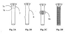
- Figure 2A is a side view of a stent according to the present invention, comprising an accordion-shaped extension (7).
- the eternal diameter of said extension (7a) is wider than the external diameter of said elongated tube (7b), thus enabling the fixation of the stent inside the lumen of the salivary gland duct. It is acknowledged that more than one of said extension is possible and a few said extension may be useful in some specific lumens.
- FIG. 2B presents a side-view of the stent according to the present invention, wherein at least one flap (6) is provided for enabling the stent to be affixed inside the salivary gland duct.
- Said flap is preferably a leaf-like polymer made article, comprising considerable elasticity which ensures efficient and consistent attachment to the interior lumen of the salivary gland duct to be treated. It is acknowledged that more than one flap is possible, and a set of a few flaps may be useful in some specific lumens.
- the flaps may be arranged side-by-side (e.g., in parallel), or one along the other as described in the aforementioned Fig. 2B .
- the stent according to the present invention comprises at least one circular array of folded flaps (6a). It is appreciated that the external diameter of the folded flaps is wider than the external diameter of the elongated tube, whereby the fixation of the stent inside the lumen of the salivary gland duct. It is further acknowledged that more than one circular array of folded flaps (6a) is possible, and a set of a few of said arrays may be useful in some specific lumens.
- Figure 2D presents a side-view of a simple polymeric stent according to the present invention, wherein the stent in affixed to the interior lumen of the salivary gland duct, only by means of suturing the stent to tissues located in the oral cavity.
- the surface of the stent, and more particularly, the walls of the polymeric tube portion of said stent might comprise porous.
- the aforementioned stent is made as an elongated sleeve, made of either porousive open-bore pipe, which was reshaped by pressure-molding, by knitting or weaving extruded polymeric fibers or by any other suitable technique.
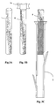
- the first member is a relatively rigid tube (A) and the second member is adapted to be conveniently inserted inside the tube (1) of the stent.
- Draw C shows the polymeric stent (1) wherein the guidance member (8, as shown in draw A) is partially inserted into the proximal rim of the stent.
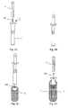
- FIG. 4 schematically presenting a method for implanting the polymeric stent into the lumen of a salivary gland duct (9) with an aided of a guidance member (8).
- Said guidance member is preferably made of relatively rigid materials, such as polymers (e.g., polymethyl metaactrylate or other acrylates, high-density polyethylene, high-density polypropylene, high-density polystyrene etc.), rubber made articles, or any suitable metal wares.
- said guidance member is an elongated tube with an external diameter, which is approximately equal to the internal diameter of the stent's tube (1).
- This guidance member (8) is preferably sterilezable member, adapted to be held conveniently by the surgeon (See for example Fig. 3B ).
- the method for the deployment of said stent is schematically presented in Fig. 3 and comprising the steps of inserting (100) an effective portion of the guidance member (8) into the tube (1) of the stent at its proximal end ( i ) ( Fig. 3A ), so the guidance member is strongly anchored inside the bore of the stent ( Fig. 3B ); inserting (200) said stent into a salivary gland duct to be treated, such that all of the tube is located in said duct (9) and such that the proximal side of said stent is located inside the oral cavity ( Fig. 3C ); and then removing (300) said guidance member (8) from the stent (Fig. 3D) whereas the stent is still anchored inside the lumen (8).
Abstract
Description
- The present invention relates to a medical device especially useful for surgical endoscopy and treatment of the salivary gland ducts. More specifically, the present invention relates to a stent-like a polymeric device comprising an elastic elongated tube; a funnel attached to said tube, comprising at least one gorge; and at least one flap, having means to anchor said stent to the salivary gland duct to be treated.
- Abnormalities and pathologies of the salivary glands are traditionally divided into four categories: (i) inflammations; (ii) infections, and (iii) obstruction to the flow of saliva and (iv) tumors. This obstruction is most commonly from the submandibular parotid and glands, usually due to stone formation and due to the presence of strictures and kinks in the salivary gland ducts.
A polyethylene tube, made of a commercially available intravenous catheter (inner diameter of 1.7 to 2.0 mm, length 45 mm) was implanted by Nahelieli et al. (see Nahlieli et al., J. Oral Maxillofac. Surg., 59:484-490, 2001) inside kinked and strictured salivary gland ducts, for two weeks. The anterior edge of this rigid tube was sutured to the mucosa ands the periosteum near the lingual side of the anterior teeth.
This preliminary stent-like conduit is characterized by many drawbacks hereto described. It does not enable the continuous drainage of saliva from the oral cavity towards the salivary gland. The immobilization of this polyethylene pipe into the injured salivary gland duct, by means of suturing it to the tissue, is tedious and inefficient. This device is not adapted to be anchored to said salivary duct, so the stent has an unstable location and thus might occasionally damage the salivary duct. Still, this rigid tube can escape from the salivary duct towards the oral cavity or the salivary gland itself and hence might produce a serious injury of these delicate organs. Lastly, and most importantly, the rigidity of the tube and its inefficient design causes severe pain to the patient. -
GB 1,518,654 - The present invention provides a polymeric stent, especially useful in surgical endoscopy and for the treatment of salivary gland ducts comprising; an elongated tube, wherein the proximal end of said tube has a funnel-like shape; and wherein said funnel further comprises at least one gorge, which enables the suturing of said stent to said duct.
- It is also provided, according to another preferred embodiment of the present invention, a polymeric stent as defined above, having means to be at least temporally anchored inside the lumen of a salivary duct. According to a preferred embodiment of the present invention, said means to encore said stent inside the lumen of the salivary gland duct is at least one wing-like flap and/or said stent comprising two wing-like flaps.
- It also provides, according to another preferred embodiment of the present invention, a polymeric stent as defined above, adapted to be at least temporally anchored inside the lumen of a salivary duct, wherein the tube additionally comprises at least one extended portion on its width. One particular embodiment is wherein the extended portion is an accordion-like member, as described in
Figure 2A , and/or a polymeric stent as defined above, additionally comprising a plurality of flaps, arranged in a circular array of folded flaps, as described inFigure 2C . - It also provides, according to another preferred embodiment of the present invention, a polymeric stent as defined above, in the length of approximately 20 to 65 mm and most particularly in the range of 32 to 48 mm.
- It also provides, according to another preferred embodiment of the present invention, a polymeric stent as defined above, wherein the internal diameter of the elongated tube is in the range of approximately 1.0 to 4.5 mm and most particularly in the range of approximately 1.5 to 3.0 mm.
- It also provides, according to another preferred embodiment of the present invention, a polymeric stent as defined above, wherein the length of the funnel-like member is in the range of approximately 1.0 to 4.5 mm and most particularly in the range of approximately 1.0 to 4.5 mm.
- It also provides, according to another preferred embodiment of the present invention, a polymeric stent as defined above, wherein the tube is selected from a porousive or a non-porousive article, made by the method selected from knitting or weaving a polymeric sleeve; extruding, cast-forming or press-molding a polymeric raw-material.
- According to another preferred embodiment of the present invention, a polymeric stent as defined above is provided, suitable for either local or systemic delivery of compounds selected from drugs and other substances.
- Still according to another preferred embodiment of the present invention, a polymeric stent as defined above is provided, wherein the drug to be delivered is selected from one or more biocides, steroidal anti-inflammatory agents, antiviral compound, analgesics, local anesthetics, anticoagulants, antihypertensive substances, vitamins and contrast media. More specifically, said biocide to be delivered is selected from cetylpyridinium chloride, benzalkonium chloride, chlorhexidine, cetyltrimethylammonium bromide, polyoxyethylene, nonylphenols, alkylaryl sulfonates, miconazole nitrate, metronidazole, trimethoprim, chloramphenicol, sulfamethoxazole; cetramide or any effective antibiotic. Additionally, amore specifically, the steroidal anti-inflammatory agents to be delivered are selected from corticosteroids and any hydrocortisone containing compositions. Moreover, said local anesthetic is preferably selected from lidocaine, adrenaline, ephedrine, epinephrine, aminophylline, and theophylline.
- It also provides, according to another preferred embodiment of the present invention, a polymeric stent as defined above, having means to be temporally anchored to said stent inside the lumen of the salivary gland duct to be treated, comprising a funnel with two gorges. Preferably, said stent is the one described in
figure 2 . - A method for implanting the polymeric stent into the lumen of a salivary gland duct as defined above is proivided, comprising; (a) inserting said stent into a salivary gland duct to be treated, such that the whole tube is located in said duct and such that the proximal side of said stent is located inside the oral cavity; and (b) suturing said stent to the mucosa and/or the periosteum near the lingual side of the anterior teeth by means of sutures, wherein said sutures are sutured to at least one gorge located in the funnel.
- A suitable guidance member may alternatively provide said method. Thus, a method for implanting the polymeric stent into the lumen of a salivary gland duct as defined above is provided, wherein the implanting the polymeric stent into the lumen of a salivary gland duct as above, is aided with a relatively rigid guidance member. Said method comprising mainly the hereto define steps of: (a) inserting an effective portion of said guidance member into the tube of the stent at its proximal end; (b) inserting said stent into a salivary gland duct to be treated, such that all of the tube is located in said duct and such that the proximal side of said stent is located inside the oral cavity; (c) removing said guidance member from the stent; and (d) suturing said stent to the mucosa and/or the periosteum near the lingual side of the anterior teeth by means of sutures, wherein said sutures are sutured to at least one gorge located in the funnel.
- It also provides, a method for implanting the polymeric stent into the lumen of a salivary gland duct as defined above, especially useful for the treatment of strictures, kinks, and any pathology of the salivary gland duct, wherein said method is especially useful for practice along and after a surgical endoscopy.
- Lastly, it also provides, a method for implanting the polymeric stent into the lumen of a salivary gland duct as defined above, wherein said treatment by the polymeric stent defined in
claim 1 and in preceding claims is for a period of approximately two weeks. -
- Figure 1
- presents a side-view of a polymeric stent comprising an elongated tube, attached funnel, two gorges and two flaps (
Fig 1A ), and a top view of said stent. - Figure 2
- presents a side view of various stents according to the present invention.
- Figure 3
- presents a side view of a polymeric stent with a guidance member, and two possible guidance members.
- Figure 4
- presents a method for implanting the polymeric stent into the lumen of a salivary gland duct with an aided of a guidance member. The method is schematically comprising the steps of inserting an effective portion of the guidance member into the tube of the stent at its proximal end (A), so the guidance member is strongly anchored inside the bore of the stent (B); inserting said stent into a salivary gland duct to be treated, such that all of the tube is located in said duct and such that the proximal side of said stent is located inside the oral cavity (C); and then removing said guidance member from the stent (D).
- The current invention contemplates the usage of any prosthesis, which can be inserted into the saliva duct in order to create a continuous passageway through said duct. When "stent" is referred to herein, it may include the classical definition of stents as they are used in known intravascular applications. "Stent" used herein also includes any prosthesis which may be inserted and held where desired in the lumen of said saliva duct.
- The following description is provided, along all chapters of the present invention, so as to enable any person skilled in the art to make use of said invention and sets forth the best modes contemplated by the inventor of carrying out this invention. Various modifications, however, will remain apparent to those skilled in the art, since the generic principles of the present invention have been defined specifically to provide for stenting and supporting the continuous flow of saliva throughout the saliva ducts.
- There are several polymeric compounds that are known to be bioabsorbable and to have the ability to be drug impregnated. These compounds include, yet not limited to poly-1-lactic acid, polyglycolic acid, polyanhydride, and polyphosphate ester, polyurethanes, polyethylene. Most specifically, theromplastic polyurethanes, such as the commercially available Estane products (such as Estane 58092), are suitable as raw-martials for the hereto-defined stent. It is further acknowledged that various coloring materials and surface coatings are suitable for use. Those raw materials may be used in their many forms, i.e., crystals, fibers, blocks, plates, etc. and in a wide range of molecular weights. Co-polymers and blends are applicable according to the present invention to form either porous or non-porous polymeric stents. The polymeric stents, according to the present invention, may be made as an extruded open-bore polymeric pipe, a woven or knitted sleeve etc. According to a preferred embodiment of the present invention, extrusion, cast-forming or press-molding techniques are suitable for the production of the polymeric stent.
- Additionally, according to a preferred embodiment of the present invention, said polymeric composition of the stent may be bio-stable or bio-absorbable. If bio-stable, a drug, as wildly defined in the present invention, would diffuse out of the polymer. Various compositions are suitable to be delivered either locally or systematically by the aforementioned polymeric stent. These release compositions are selected for drugs, and any other desired materials, including, yet not limited to one or more biocides, steroidal anti-inflammatory agents, antiviral compound, analgesics, local anesthetics, anticoagulants, antihypertensive substances, vitamins and contrast media.
- According to another preferred embodiment of the present invention, steroidal anti-inflammatory agents may be used, comprising, but not limited to, corticosteroids such as hydrocortisone, hydroxyltriamcinolone, alpha-methyl dexamethasone, dexamethasone-phosphate, beclomethasone dipropionates, clobetasol valerate, desonide, desoxymethasone, desoxycorticosterone acetate, dexamethasone, dichlorisone, diflorasone diacetate, diflucortolone valerate, fluadrenolone, fluclorolone acetonide, fludrocortisone, flumethasone pivalate, fluosinolone acetonide, fluocinonide, flucortine butylesters, fluocortolone, fluprednidene (fluprednylidene) acetate, flurandrenolone, halcinonide, hydrocortisone acetate, hydrocortisone butyrate, methylprednisolone, triamcinolone acetonide, cortisone, cortodoxone, flucetonide, fludrocortisone, difluorosone diacetate, fluradrenolone, fludrocortisone, diflurosone diacetate, fluradrenolone acetonide, medrysone, amcinafel, amcinafide, betamethasone and the balance of its esters, chloroprednisone, chlorprednisone acetate, clocortelone, clescinolone, dichlorisone, diflurprednate, flucloronide, flunisolide, fluoromethalone, fluperolone, fluprednisolone, hydrocortisone valerate, hydrocortisone cyclopentylpropionate, hydrocortamate, meprednisone, paramethasone, prednisolone, prednisone, beclomethasone dipropionate, triamcinolone, and mixtures thereof may be used. The preferred steroidal anti-inflammatory for use is hydrocortisone.
- According to another preferred embodiment of the present invention, at least two antiviral compounds may be used, comprising, but not limited to acyclovir and interferon.
- According to another preferred embodiment of the present invention, steroidal analgesics may be used, comprising, but not limited to aspirin, salicylic acid, diflunisal, morphine and its salts and the like.
- According to another preferred embodiment of the present invention, antiseptic substances may be used, comprising, but not limited to cetylpyridinium chloride, benzalkonium chloride, chlorhexidine and the like.
- According to another preferred embodiment of the present invention, antimycotic substances may be used, comprising, but not limited to cetyltrimethylammonium bromide and the like.
- According to another preferred embodiment of the present invention antifungals, may be used, comprising, but not limited to polyoxyethylene nonylphenols, alkylaryl sulfonates, miconazole nitrate, metronidazole, trimethoprim and the like.
- According to another preferred embodiment of the present invention, antiprotozoals may be used, comprising, but not limited to chloramphenicol, sulfamethoxazole and the like.
- According to another preferred embodiment of the present invention, local anesthetics may be used, comprising, but not limited to salts of procaine, benzocaine, lidocain, procain, bupivacaine, tetracain, xylocaine, mepivacaine and their salts and the like; antiasthma drugs such as adrenaline, ephedrine, epinephrine, aminophylline, theophylline and the like.
- According to another preferred embodiment of the present invention anticoagulants, may be used, comprising, but not limited to heparin and its salts, such as calcium and sodium heparin, bishydroxycoumarin and the like.
- According to another preferred embodiment of the present invention antihypertensive, may be used, comprising, but not limited to methyldopa, hydralazine, clonidine, chlorothiazide, timolol, propanolol, metroprolol, prazosin hydrochloride, furosemide and the like.
- According to another preferred embodiment of the present invention, vitamins may be used, comprising, but not limited to such as B6, B12 and C and the like.
- According to another preferred embodiment of the present invention contrast media, may be used, comprising, but not limited to BaSO4, iohexol and other iodine-containing substances and the like (x-ray), iron(II,III)oxide particles, titanium dioxide pigments, and other ferromagnetic materials (magnetic resonance imaging). It is acknowledged in this respect, that various coloring materials, such as 14-4007 PV fast violet pigments, are possible ingredients of the material forming or coating the stents.
- Reference is made now to
Figure 1 , presenting one preferred embodiment of the polymeric stent according to the present. Said stent comprises an elongated open-bore polymeric tube (1), comprising a proximal rim (i) located adjacent to the oral cavity when implanted in the salivary gland duct, and a distal rim (ii), located adjacent to the salivary gland when implanted in the salivary gland duct. The aforementioned stent additionally comprises a funnel (2), located in the proximal rim of said tube. The inner diameter of said tube at the proximal rim is equal to the inner diameter of the funnel at its distal rim (4), wherein the inner diameter of the funnel at the proximal rim is wider than at the distal rim (3). Said funnel is preferably comprises of at least one gorge, which is a hole in the wall of said funnel, that enables the surgeon implanting said stent to suture it easily and efficiently. The stent might comprise a few gorges, wherein two gorges are sufficient to anchor the stent in its desired location inside the salivary gland duct. - Additionally or alternatively, the stent according to the present invention, comprises at least one flap, ensuring that the stent is fixed to its desired position without any undesirable movement along the salivary gland duct.
Figure 1B present a top view of the stent, takes from the proximal rim (3) of the stent to its distal end (4), comprising two gorges (5a, 5b). It is acknowledged that the hereto-described stent may comprise between one to four gorges. Nonetheless, more gorges are possible, and may be useful in some cases. - Reference is made now to
Figure 2 , presenting preferred embodiments of the hereto-defined polymeric stent.Figure 2A is a side view of a stent according to the present invention, comprising an accordion-shaped extension (7). The eternal diameter of said extension (7a) is wider than the external diameter of said elongated tube (7b), thus enabling the fixation of the stent inside the lumen of the salivary gland duct. It is acknowledged that more than one of said extension is possible and a few said extension may be useful in some specific lumens. -
Figure 2B presents a side-view of the stent according to the present invention, wherein at least one flap (6) is provided for enabling the stent to be affixed inside the salivary gland duct. Said flap is preferably a leaf-like polymer made article, comprising considerable elasticity which ensures efficient and consistent attachment to the interior lumen of the salivary gland duct to be treated. It is acknowledged that more than one flap is possible, and a set of a few flaps may be useful in some specific lumens. The flaps may be arranged side-by-side (e.g., in parallel), or one along the other as described in the aforementionedFig. 2B . - Referring now
Figure 2C , the stent according to the present invention comprises at least one circular array of folded flaps (6a). It is appreciated that the external diameter of the folded flaps is wider than the external diameter of the elongated tube, whereby the fixation of the stent inside the lumen of the salivary gland duct. It is further acknowledged that more than one circular array of folded flaps (6a) is possible, and a set of a few of said arrays may be useful in some specific lumens. -
Figure 2D presents a side-view of a simple polymeric stent according to the present invention, wherein the stent in affixed to the interior lumen of the salivary gland duct, only by means of suturing the stent to tissues located in the oral cavity. Moreover, as schematically described inFig. 2D , the surface of the stent, and more particularly, the walls of the polymeric tube portion of said stent might comprise porous. Thus, according to one preferable embodiment of the present invention, the aforementioned stent is made as an elongated sleeve, made of either porousive open-bore pipe, which was reshaped by pressure-molding, by knitting or weaving extruded polymeric fibers or by any other suitable technique. - Reference is still made to
Figure 3 , schematically presenting two guidance members (8). The first member is a relatively rigid tube (A) and the second member is adapted to be conveniently inserted inside the tube (1) of the stent. Draw C shows the polymeric stent (1) wherein the guidance member (8, as shown in draw A) is partially inserted into the proximal rim of the stent. - Reference is lastly made to
Figure 4 , schematically presenting a method for implanting the polymeric stent into the lumen of a salivary gland duct (9) with an aided of a guidance member (8). Said guidance member is preferably made of relatively rigid materials, such as polymers (e.g., polymethyl metaactrylate or other acrylates, high-density polyethylene, high-density polypropylene, high-density polystyrene etc.), rubber made articles, or any suitable metal wares. In one preferred embodiment, said guidance member is an elongated tube with an external diameter, which is approximately equal to the internal diameter of the stent's tube (1). This guidance member (8) is preferably sterilezable member, adapted to be held conveniently by the surgeon (See for exampleFig. 3B ). - The method for the deployment of said stent is schematically presented in
Fig. 3 and comprising the steps of inserting (100) an effective portion of the guidance member (8) into the tube (1) of the stent at its proximal end (i) (Fig. 3A ), so the guidance member is strongly anchored inside the bore of the stent (Fig. 3B ); inserting (200) said stent into a salivary gland duct to be treated, such that all of the tube is located in said duct (9) and such that the proximal side of said stent is located inside the oral cavity (Fig. 3C ); and then removing (300) said guidance member (8) from the stent (Fig. 3D) whereas the stent is still anchored inside the lumen (8).
Claims (24)
- A polymeric stent, especially useful in an oral cavity, comprising; an elongated tube (1), wherein the proximal end of said tube comprises a funnel (2), said funnel (2) has a funnel wall, characterized in that the funnel (2) comprises at least one gorge(s) in said wall for enabling suturing of said stent to a salivary gland duct (9) in the oral cavity.
- The polymeric stent according to claim 1, having means to be at least temporary anchored inside the lumen of a salivary duct.
- The polymeric stent according to claim 2, wherein said means to anchor said stent inside the lumen of the salivary gland duct (9) is at least one wing-like flap (6).
- The polymeric stent according to claim 2, comprising two wing-like flaps (6).
- The polymeric stent according to claim 2, adapted to be at least temporally anchored inside the lumen of a salivary duct, wherein the tube (1) additionally comprises at least one extended portion on its width.
- The polymeric stent as defined in claim 5, wherein the extended portion comprises an accordion-like member (7).
- The polymeric stent as defined in claim 2, additionally comprising a plurality of flaps (6), arranged in a circular array of folded flaps.
- The polymeric stent according to claim 1, in the length of approximately 20 to 65 mm.
- The polymeric stent according to claim 1, in the length of approximately 32 to 48 mm.
- The polymeric stent as defined in claim 1, wherein the internal diameter of the elongated tube (1) is in the range of approximately 1.0 to 4.5 mm.
- The polymeric stent according to claim 1, wherein the internal diameter of the elongated tube (1) is in the range of approximately 1.5 to 3.0 mm.
- The polymeric stent according to claim 1, wherein the length of the funnel-like member is in the range of approximately 1.0 to 4.5 mm.
- The polymeric stent according to claim 1, wherein the internal diameter of the funnel-like member is in the range of approximately 1.0 to 4.5 mm.
- The polymeric stent according to claim 1, wherein said funnel wall comprises a generally uniform thickness when viewed in side view.
- The polymeric stent according to claim 1, wherein the stent is made from any one of: poly-1-lactic acid, polyglycolic acid, polyanhydride, polyphosphate ester, polyurethanes, polyethylene.
- The polymeric stent according to claim 1, wherein the tube (1) is selected from a porous or a non-porous article, made by the method selected from knitting or weaving a polymeric sleeve; extruding, cast-forming or press-molding a polymeric raw-material.
- The polymeric stent according to claim 1, wherein the stent is made from one of a bio-stable and a bioabsorbable material adapted suitable for either local or systemic delivery of compounds selected from drugs and other substances.
- The polymeric stent according to claim 17, wherein the stent comprises said compound, said compound comprising a drug selected from one or more biocides, steroidal anti-inflammatory agents, antiviral compound, analgesics, local anesthetics, anticoagulants, antihypertensive substances, vitamins and contrast media.
- The polymeric stent according to claim 18, wherein the stent comprises said compound, said compound comprising a biocide selected from cetylpyridinium chloride, benzalkonium chloride, chlorhexidine, cetyltrimethylammonium bromide, polyoxyethylene, nonylphenols, alkylaryl sulfonates, miconazole nitrate, metronidazole, trimethoprim, chloramphenicol, sulfamethoxazole; cetramide or any effective antibiotic.
- The polymeric stent according to claim 18, wherein the stent comprises said compound, said compound comprising steroidal anti-inflammatory agents selected from corticosteroids and any hydrocortisone containing compositions.
- The polymeric stent according to claim 18, wherein the stent comprises said compound, said compound comprising a local anesthetic selected from lidocaine, adrenaline, ephedrine, epinephrine, aminophylline, and theophylline.
- The polymeric stent according to claim 1, having means to be temporally anchored to said stent inside the lumen of the salivary gland duct (9) to be treated, comprising a funnel with two gorges (5a,5b).
- A stent according to any one of claims 1 to 22, further comprising a guidance member (8) adapted for being accommodated within a bore of the stent.
- A stent system according to claim 23, wherein said guidance member (8) comprises a substantially rigid member.
Applications Claiming Priority (3)
| Application Number | Priority Date | Filing Date | Title |
|---|---|---|---|
| IL14861602 | 2002-03-11 | ||
| IL148616A IL148616A (en) | 2002-03-11 | 2002-03-11 | Polymeric stent useful for the treatment of the salivary gland ducts |
| PCT/IL2002/000861 WO2003075794A1 (en) | 2002-03-11 | 2002-10-28 | A polymeric stent useful for the treatment of the salivary gland ducts and method for using the same |
Publications (2)
| Publication Number | Publication Date |
|---|---|
| EP1501447A1 EP1501447A1 (en) | 2005-02-02 |
| EP1501447B1 true EP1501447B1 (en) | 2009-03-11 |
Family
ID=27799846
Family Applications (1)
| Application Number | Title | Priority Date | Filing Date |
|---|---|---|---|
| EP02807031A Expired - Lifetime EP1501447B1 (en) | 2002-03-11 | 2002-10-28 | A polymeric stent useful for the treatment of the salivary gland ducts |
Country Status (8)
| Country | Link |
|---|---|
| US (3) | US7195646B2 (en) |
| EP (1) | EP1501447B1 (en) |
| AT (1) | ATE424785T1 (en) |
| AU (1) | AU2002367760A1 (en) |
| DE (1) | DE60231557D1 (en) |
| ES (1) | ES2322987T3 (en) |
| IL (1) | IL148616A (en) |
| WO (1) | WO2003075794A1 (en) |
Cited By (3)
| Publication number | Priority date | Publication date | Assignee | Title |
|---|---|---|---|---|
| DE102008040791A1 (en) * | 2008-07-28 | 2010-02-04 | Biotronik Vi Patent Ag | Endoprosthesis and method of making the same |
| US9974563B2 (en) | 2014-05-28 | 2018-05-22 | Cook Medical Technologies Llc | Medical devices having a releasable member and methods of using the same |
| US10166017B2 (en) | 2013-08-05 | 2019-01-01 | Cook Medical Technologies Llc | Medical devices having a releasable tubular member and methods of using the same |
Families Citing this family (21)
| Publication number | Priority date | Publication date | Assignee | Title |
|---|---|---|---|---|
| US8088060B2 (en) | 2000-03-15 | 2012-01-03 | Orbusneich Medical, Inc. | Progenitor endothelial cell capturing with a drug eluting implantable medical device |
| US9522217B2 (en) | 2000-03-15 | 2016-12-20 | Orbusneich Medical, Inc. | Medical device with coating for capturing genetically-altered cells and methods for using same |
| US8821549B2 (en) | 2006-06-13 | 2014-09-02 | Anova Corporation | Methods and apparatus for anulus repair |
| US8834496B2 (en) | 2006-06-13 | 2014-09-16 | Bret A. Ferree | Soft tissue repair methods and apparatus |
| US9232938B2 (en) | 2006-06-13 | 2016-01-12 | Anova Corp. | Method and apparatus for closing fissures in the annulus fibrosus |
| US8764835B2 (en) | 2006-06-13 | 2014-07-01 | Bret A. Ferree | Intervertebral disc treatment methods and apparatus |
| US9622888B2 (en) * | 2006-11-16 | 2017-04-18 | W. L. Gore & Associates, Inc. | Stent having flexibly connected adjacent stent elements |
| US8974514B2 (en) | 2007-03-13 | 2015-03-10 | Abbott Cardiovascular Systems Inc. | Intravascular stent with integrated link and ring strut |
| EP2214569A2 (en) * | 2007-11-01 | 2010-08-11 | Anova Corporation | Methods and apparatus for anulus repair |
| US8926688B2 (en) | 2008-01-11 | 2015-01-06 | W. L. Gore & Assoc. Inc. | Stent having adjacent elements connected by flexible webs |
| US20100100170A1 (en) * | 2008-10-22 | 2010-04-22 | Boston Scientific Scimed, Inc. | Shape memory tubular stent with grooves |
| GB0921203D0 (en) * | 2009-12-03 | 2010-01-20 | Al Lamee Kadem G | Drugs formulations for cardiovascular stents |
| US8603185B2 (en) * | 2010-03-11 | 2013-12-10 | Cook Medical Technologies Llc | Stent geometry |
| US9662195B2 (en) | 2010-07-09 | 2017-05-30 | E. Benson Hood Laboratories | Implant device for use in salivary gland duct |
| US8517971B2 (en) * | 2010-07-09 | 2013-08-27 | E. Benson Hood Laboratories | Cannula implant device for use in salivary gland ducts |
| US9913661B2 (en) | 2014-08-04 | 2018-03-13 | Cook Medical Technologies Llc | Medical devices having a releasable tubular member and methods of using the same |
| WO2016057740A1 (en) | 2014-10-09 | 2016-04-14 | Boston Scientific Scimed, Inc. | Pancreatic stent with drainage feature |
| US10299948B2 (en) | 2014-11-26 | 2019-05-28 | W. L. Gore & Associates, Inc. | Balloon expandable endoprosthesis |
| US10568752B2 (en) | 2016-05-25 | 2020-02-25 | W. L. Gore & Associates, Inc. | Controlled endoprosthesis balloon expansion |
| JP7348292B2 (en) | 2019-01-07 | 2023-09-20 | ボストン サイエンティフィック サイムド,インコーポレイテッド | Stent with anti-migration mechanism |
| KR20230116879A (en) | 2020-12-02 | 2023-08-04 | 보스톤 싸이엔티픽 싸이메드 인코포레이티드 | Stents with improved deployment properties |
Family Cites Families (13)
| Publication number | Priority date | Publication date | Assignee | Title |
|---|---|---|---|---|
| US3788327A (en) * | 1971-03-30 | 1974-01-29 | H Donowitz | Surgical implant device |
| US3818511A (en) * | 1972-11-17 | 1974-06-25 | Medical Prod Corp | Medical prosthesis for ducts or conduits |
| US3938529A (en) * | 1974-07-22 | 1976-02-17 | Gibbons Robert P | Indwelling ureteral catheter |
| GB1518654A (en) * | 1977-03-16 | 1978-07-19 | Celestin L | Devices for effecting endo-oesophageal intubation |
| GB8822732D0 (en) * | 1988-09-28 | 1988-11-02 | Nat Res Dev | Cervical prosthesis |
| US4973301A (en) * | 1989-07-11 | 1990-11-27 | Israel Nissenkorn | Catheter and method of using same |
| CH680263A5 (en) * | 1989-07-20 | 1992-07-31 | Norman Godin | |
| US5599291A (en) * | 1993-01-04 | 1997-02-04 | Menlo Care, Inc. | Softening expanding ureteral stent |
| SE505436C2 (en) * | 1993-04-27 | 1997-08-25 | Ams Medinvent Sa | prostatic stent |
| US5466242A (en) | 1994-02-02 | 1995-11-14 | Mori; Katsushi | Stent for biliary, urinary or vascular system |
| US5968058A (en) * | 1996-03-27 | 1999-10-19 | Optonol Ltd. | Device for and method of implanting an intraocular implant |
| US6764519B2 (en) * | 2000-05-26 | 2004-07-20 | Scimed Life Systems, Inc. | Ureteral stent |
| US6770101B2 (en) * | 2001-10-09 | 2004-08-03 | Scimed Life Systems, Inc. | Prostatic stent and delivery system |
-
2002
- 2002-03-11 IL IL148616A patent/IL148616A/en not_active IP Right Cessation
- 2002-10-28 AT AT02807031T patent/ATE424785T1/en not_active IP Right Cessation
- 2002-10-28 WO PCT/IL2002/000861 patent/WO2003075794A1/en not_active Application Discontinuation
- 2002-10-28 AU AU2002367760A patent/AU2002367760A1/en not_active Abandoned
- 2002-10-28 US US10/507,304 patent/US7195646B2/en not_active Expired - Fee Related
- 2002-10-28 ES ES02807031T patent/ES2322987T3/en not_active Expired - Lifetime
- 2002-10-28 DE DE60231557T patent/DE60231557D1/en not_active Expired - Lifetime
- 2002-10-28 EP EP02807031A patent/EP1501447B1/en not_active Expired - Lifetime
-
2007
- 2007-03-05 US US11/682,031 patent/US7507258B2/en not_active Expired - Fee Related
-
2008
- 2008-12-22 US US12/341,234 patent/US20090105841A1/en not_active Abandoned
Cited By (3)
| Publication number | Priority date | Publication date | Assignee | Title |
|---|---|---|---|---|
| DE102008040791A1 (en) * | 2008-07-28 | 2010-02-04 | Biotronik Vi Patent Ag | Endoprosthesis and method of making the same |
| US10166017B2 (en) | 2013-08-05 | 2019-01-01 | Cook Medical Technologies Llc | Medical devices having a releasable tubular member and methods of using the same |
| US9974563B2 (en) | 2014-05-28 | 2018-05-22 | Cook Medical Technologies Llc | Medical devices having a releasable member and methods of using the same |
Also Published As
| Publication number | Publication date |
|---|---|
| IL148616A0 (en) | 2004-07-25 |
| US20070162148A1 (en) | 2007-07-12 |
| EP1501447A1 (en) | 2005-02-02 |
| WO2003075794A1 (en) | 2003-09-18 |
| US20090105841A1 (en) | 2009-04-23 |
| IL148616A (en) | 2008-03-20 |
| ES2322987T3 (en) | 2009-07-03 |
| US7195646B2 (en) | 2007-03-27 |
| ATE424785T1 (en) | 2009-03-15 |
| US20050125071A1 (en) | 2005-06-09 |
| DE60231557D1 (en) | 2009-04-23 |
| AU2002367760A1 (en) | 2003-09-22 |
| US7507258B2 (en) | 2009-03-24 |
Similar Documents
| Publication | Publication Date | Title |
|---|---|---|
| US7507258B2 (en) | Polymeric stent useful for the treatment of the salivary gland ducts and method for using the same | |
| US7287983B2 (en) | Polymeric dental implant | |
| AU2001243646B2 (en) | Sheaths for implantable fixation devices | |
| US20170296309A1 (en) | Bioresorbable Inflatable Devices, Incision Tool And Methods For Tissue Expansion And Tissue Regeneration | |
| EP0916362B1 (en) | Stent for vessels | |
| US7758631B2 (en) | Bioabsorbable endoprosthesis having elongate axial reservoir for by-product collection | |
| JP4236863B2 (en) | Removable stent for internal lumen | |
| EP1112724A2 (en) | Removable stent for body lumens | |
| EP1527756A3 (en) | Stent aneurysm treatment system and method | |
| JP2024028635A (en) | Tubular implant with controlled biodegradation | |
| JP2024515282A (en) | Sutures with drug-containing outer filaments | |
| AU2005202598B2 (en) | Sheaths for implantable fixation devices |
Legal Events
| Date | Code | Title | Description |
|---|---|---|---|
| PUAI | Public reference made under article 153(3) epc to a published international application that has entered the european phase |
Free format text: ORIGINAL CODE: 0009012 |
|
| 17P | Request for examination filed |
Effective date: 20041011 |
|
| AK | Designated contracting states |
Kind code of ref document: A1 Designated state(s): AT BE BG CH CY CZ DE DK EE ES FI FR GB GR IE IT LI LU MC NL PT SE SK TR |
|
| AX | Request for extension of the european patent |
Extension state: AL LT LV MK RO SI |
|
| 17Q | First examination report despatched |
Effective date: 20061006 |
|
| GRAP | Despatch of communication of intention to grant a patent |
Free format text: ORIGINAL CODE: EPIDOSNIGR1 |
|
| RTI1 | Title (correction) |
Free format text: A POLYMERIC STENT USEFUL FOR THE TREATMENT OF THE SALIVARY GLAND DUCTS |
|
| GRAS | Grant fee paid |
Free format text: ORIGINAL CODE: EPIDOSNIGR3 |
|
| GRAS | Grant fee paid |
Free format text: ORIGINAL CODE: EPIDOSNIGR3 |
|
| GRAA | (expected) grant |
Free format text: ORIGINAL CODE: 0009210 |
|
| AK | Designated contracting states |
Kind code of ref document: B1 Designated state(s): AT BE BG CH CY CZ DE DK EE ES FI FR GB GR IE IT LI LU MC NL PT SE SK TR |
|
| REG | Reference to a national code |
Ref country code: GB Ref legal event code: FG4D |
|
| REG | Reference to a national code |
Ref country code: CH Ref legal event code: EP |
|
| REG | Reference to a national code |
Ref country code: IE Ref legal event code: FG4D |
|
| REF | Corresponds to: |
Ref document number: 60231557 Country of ref document: DE Date of ref document: 20090423 Kind code of ref document: P |
|
| REG | Reference to a national code |
Ref country code: ES Ref legal event code: FG2A Ref document number: 2322987 Country of ref document: ES Kind code of ref document: T3 |
|
| PG25 | Lapsed in a contracting state [announced via postgrant information from national office to epo] |
Ref country code: NL Free format text: LAPSE BECAUSE OF FAILURE TO SUBMIT A TRANSLATION OF THE DESCRIPTION OR TO PAY THE FEE WITHIN THE PRESCRIBED TIME-LIMIT Effective date: 20090311 Ref country code: FI Free format text: LAPSE BECAUSE OF FAILURE TO SUBMIT A TRANSLATION OF THE DESCRIPTION OR TO PAY THE FEE WITHIN THE PRESCRIBED TIME-LIMIT Effective date: 20090311 |
|
| NLV1 | Nl: lapsed or annulled due to failure to fulfill the requirements of art. 29p and 29m of the patents act | ||
| PG25 | Lapsed in a contracting state [announced via postgrant information from national office to epo] |
Ref country code: SE Free format text: LAPSE BECAUSE OF FAILURE TO SUBMIT A TRANSLATION OF THE DESCRIPTION OR TO PAY THE FEE WITHIN THE PRESCRIBED TIME-LIMIT Effective date: 20090611 Ref country code: AT Free format text: LAPSE BECAUSE OF FAILURE TO SUBMIT A TRANSLATION OF THE DESCRIPTION OR TO PAY THE FEE WITHIN THE PRESCRIBED TIME-LIMIT Effective date: 20090311 |
|
| PG25 | Lapsed in a contracting state [announced via postgrant information from national office to epo] |
Ref country code: BE Free format text: LAPSE BECAUSE OF FAILURE TO SUBMIT A TRANSLATION OF THE DESCRIPTION OR TO PAY THE FEE WITHIN THE PRESCRIBED TIME-LIMIT Effective date: 20090311 |
|
| PG25 | Lapsed in a contracting state [announced via postgrant information from national office to epo] |
Ref country code: PT Free format text: LAPSE BECAUSE OF FAILURE TO SUBMIT A TRANSLATION OF THE DESCRIPTION OR TO PAY THE FEE WITHIN THE PRESCRIBED TIME-LIMIT Effective date: 20090824 Ref country code: EE Free format text: LAPSE BECAUSE OF FAILURE TO SUBMIT A TRANSLATION OF THE DESCRIPTION OR TO PAY THE FEE WITHIN THE PRESCRIBED TIME-LIMIT Effective date: 20090311 Ref country code: CZ Free format text: LAPSE BECAUSE OF FAILURE TO SUBMIT A TRANSLATION OF THE DESCRIPTION OR TO PAY THE FEE WITHIN THE PRESCRIBED TIME-LIMIT Effective date: 20090311 |
|
| PG25 | Lapsed in a contracting state [announced via postgrant information from national office to epo] |
Ref country code: SK Free format text: LAPSE BECAUSE OF FAILURE TO SUBMIT A TRANSLATION OF THE DESCRIPTION OR TO PAY THE FEE WITHIN THE PRESCRIBED TIME-LIMIT Effective date: 20090311 |
|
| PLBE | No opposition filed within time limit |
Free format text: ORIGINAL CODE: 0009261 |
|
| STAA | Information on the status of an ep patent application or granted ep patent |
Free format text: STATUS: NO OPPOSITION FILED WITHIN TIME LIMIT |
|
| PG25 | Lapsed in a contracting state [announced via postgrant information from national office to epo] |
Ref country code: BG Free format text: LAPSE BECAUSE OF FAILURE TO SUBMIT A TRANSLATION OF THE DESCRIPTION OR TO PAY THE FEE WITHIN THE PRESCRIBED TIME-LIMIT Effective date: 20090611 Ref country code: DK Free format text: LAPSE BECAUSE OF FAILURE TO SUBMIT A TRANSLATION OF THE DESCRIPTION OR TO PAY THE FEE WITHIN THE PRESCRIBED TIME-LIMIT Effective date: 20090311 |
|
| 26N | No opposition filed |
Effective date: 20091214 |
|
| PG25 | Lapsed in a contracting state [announced via postgrant information from national office to epo] |
Ref country code: MC Free format text: LAPSE BECAUSE OF NON-PAYMENT OF DUE FEES Effective date: 20091031 |
|
| REG | Reference to a national code |
Ref country code: CH Ref legal event code: PL |
|
| PG25 | Lapsed in a contracting state [announced via postgrant information from national office to epo] |
Ref country code: GR Free format text: LAPSE BECAUSE OF FAILURE TO SUBMIT A TRANSLATION OF THE DESCRIPTION OR TO PAY THE FEE WITHIN THE PRESCRIBED TIME-LIMIT Effective date: 20090612 Ref country code: LI Free format text: LAPSE BECAUSE OF NON-PAYMENT OF DUE FEES Effective date: 20091031 Ref country code: IE Free format text: LAPSE BECAUSE OF NON-PAYMENT OF DUE FEES Effective date: 20091028 Ref country code: CH Free format text: LAPSE BECAUSE OF NON-PAYMENT OF DUE FEES Effective date: 20091031 |
|
| PG25 | Lapsed in a contracting state [announced via postgrant information from national office to epo] |
Ref country code: LU Free format text: LAPSE BECAUSE OF NON-PAYMENT OF DUE FEES Effective date: 20091028 |
|
| PG25 | Lapsed in a contracting state [announced via postgrant information from national office to epo] |
Ref country code: TR Free format text: LAPSE BECAUSE OF FAILURE TO SUBMIT A TRANSLATION OF THE DESCRIPTION OR TO PAY THE FEE WITHIN THE PRESCRIBED TIME-LIMIT Effective date: 20090311 |
|
| PG25 | Lapsed in a contracting state [announced via postgrant information from national office to epo] |
Ref country code: CY Free format text: LAPSE BECAUSE OF FAILURE TO SUBMIT A TRANSLATION OF THE DESCRIPTION OR TO PAY THE FEE WITHIN THE PRESCRIBED TIME-LIMIT Effective date: 20090311 |
|
| PGFP | Annual fee paid to national office [announced via postgrant information from national office to epo] |
Ref country code: FR Payment date: 20121204 Year of fee payment: 11 Ref country code: DE Payment date: 20121030 Year of fee payment: 11 |
|
| PGFP | Annual fee paid to national office [announced via postgrant information from national office to epo] |
Ref country code: IT Payment date: 20121031 Year of fee payment: 11 Ref country code: ES Payment date: 20121127 Year of fee payment: 11 Ref country code: GB Payment date: 20121030 Year of fee payment: 11 |
|
| GBPC | Gb: european patent ceased through non-payment of renewal fee |
Effective date: 20131028 |
|
| PG25 | Lapsed in a contracting state [announced via postgrant information from national office to epo] |
Ref country code: GB Free format text: LAPSE BECAUSE OF NON-PAYMENT OF DUE FEES Effective date: 20131028 |
|
| REG | Reference to a national code |
Ref country code: FR Ref legal event code: ST Effective date: 20140630 |
|
| REG | Reference to a national code |
Ref country code: DE Ref legal event code: R119 Ref document number: 60231557 Country of ref document: DE Effective date: 20140501 |
|
| PG25 | Lapsed in a contracting state [announced via postgrant information from national office to epo] |
Ref country code: DE Free format text: LAPSE BECAUSE OF NON-PAYMENT OF DUE FEES Effective date: 20140501 Ref country code: FR Free format text: LAPSE BECAUSE OF NON-PAYMENT OF DUE FEES Effective date: 20131031 Ref country code: IT Free format text: LAPSE BECAUSE OF NON-PAYMENT OF DUE FEES Effective date: 20131028 |
|
| REG | Reference to a national code |
Ref country code: ES Ref legal event code: FD2A Effective date: 20150507 |
|
| PG25 | Lapsed in a contracting state [announced via postgrant information from national office to epo] |
Ref country code: ES Free format text: LAPSE BECAUSE OF NON-PAYMENT OF DUE FEES Effective date: 20131029 |