EP1501298A1 - Method and apparatus of identifying a telecine portion and bad-edits in a video sequence - Google Patents
Method and apparatus of identifying a telecine portion and bad-edits in a video sequence Download PDFInfo
- Publication number
- EP1501298A1 EP1501298A1 EP20040102871 EP04102871A EP1501298A1 EP 1501298 A1 EP1501298 A1 EP 1501298A1 EP 20040102871 EP20040102871 EP 20040102871 EP 04102871 A EP04102871 A EP 04102871A EP 1501298 A1 EP1501298 A1 EP 1501298A1
- Authority
- EP
- European Patent Office
- Prior art keywords
- pull
- image
- detecting
- sads
- down image
- Prior art date
- Legal status (The legal status is an assumption and is not a legal conclusion. Google has not performed a legal analysis and makes no representation as to the accuracy of the status listed.)
- Granted
Links
Images


Classifications
-
- H—ELECTRICITY
- H04—ELECTRIC COMMUNICATION TECHNIQUE
- H04N—PICTORIAL COMMUNICATION, e.g. TELEVISION
- H04N5/00—Details of television systems
- H04N5/222—Studio circuitry; Studio devices; Studio equipment
- H04N5/253—Picture signal generating by scanning motion picture films or slide opaques, e.g. for telecine
-
- H—ELECTRICITY
- H04—ELECTRIC COMMUNICATION TECHNIQUE
- H04N—PICTORIAL COMMUNICATION, e.g. TELEVISION
- H04N7/00—Television systems
- H04N7/01—Conversion of standards, e.g. involving analogue television standards or digital television standards processed at pixel level
- H04N7/0112—Conversion of standards, e.g. involving analogue television standards or digital television standards processed at pixel level one of the standards corresponding to a cinematograph film standard
- H04N7/0115—Conversion of standards, e.g. involving analogue television standards or digital television standards processed at pixel level one of the standards corresponding to a cinematograph film standard with details on the detection of a particular field or frame pattern in the incoming video signal, e.g. 3:2 pull-down pattern
-
- H—ELECTRICITY
- H04—ELECTRIC COMMUNICATION TECHNIQUE
- H04N—PICTORIAL COMMUNICATION, e.g. TELEVISION
- H04N7/00—Television systems
- H04N7/01—Conversion of standards, e.g. involving analogue television standards or digital television standards processed at pixel level
- H04N7/0117—Conversion of standards, e.g. involving analogue television standards or digital television standards processed at pixel level involving conversion of the spatial resolution of the incoming video signal
- H04N7/012—Conversion between an interlaced and a progressive signal
Definitions
- the present invention relates to a method and associated apparatus for detecting a bad-edit portion of a television signal.
- 16 frames per second is the minimum sampling frequency (i.e., Nyquist frequency) for sampling a signal for which information will be preserved.
- Nyquist frequency the minimum sampling frequency for sampling a signal for which information will be preserved.
- an image for a movie is processed at a speed of 24 frames per second
- an image for a television (TV) is processed at a speed of 25 to 30 frames per second.
- a movie film uses a progressive system that instantaneously stores every picture in a film and progressively projects the pictures on a screen.
- a TV since an image is basically transmitted over airwaves, each picture is filmed and transmitted by the scanning of several hundreds of scanning lines, and then displaying the scanned lines on a screen of a cathode ray (or Braun) tube after transmission.
- NTSC National Television System Committee
- PAL Phase Alternation by Line
- SECAM Sequential Couleur a Memoire
- the TV uses an interlaced scanning method which divides one picture (i.e., frame) into two fields and alternately scans the two fields in order to effectively present a moving image using limited scanning lines.
- the divided fields are called top and bottom fields, odd and even fields, upper and lower fields, etc.
- the NTSC system processes 60 fields of image per second
- the PAL or SECAM system processes 50 fields of image per second.
- every frame of movie film is passed through a converter called a telecine (which is a compound word of a television and a cinema). If the films are reproduced at TV picture reproducing speed without matching the number of film frames per second to the number of television frames per second, a viewer watches the image in fast motion. This is because the NTSC system provides 30 frame per second compared with 24 frames as is the case for movie film. Accordingly, in order to transmit the movie film to the television operating on the NTSC system, 24 frames of film per second have to be conerted into 60 television fields. This translation is achieved by obtaining 5 fields from 2 frames of film pictures.
- a simple and practically used method is to scan 3 fields for the first film picture and to scan 2 fields for the other, which is called "3:2 pull-down method".
- 50 fields should be obtained from 25 pictures (i.e., frames). This means two fields should be obtained with respect to one frame. This method of scanning two fields with respect to a frame is called a “2:2 pull-down" system.
- FIG. 1 is a view showing the 3:2 pull-down processing.
- two frames are scanned and converted into 5 fields.
- One film frame is therefore composed of a top field of odd-number lines and a bottom field of even-number lines.
- a top field of a frame 1 is expressed by T1, a bottom field of the frame 1 by B1, a top field of a frame 2 by T2, and a bottom field of the frame 2 by B2.
- FIG. 2 is a block diagram showing a known 3:2 pull-down image detection process.
- 10 fields detected by the 3:2 pull-down are F1, F2, F3, F4, F5, F6, F7, F8, F9, and F10
- a film mode is detected by using the periodicity of a Summed Absolute Difference (SAD), which is 5.
- SAD Summed Absolute Difference
- the SADs of F1-F3, F6-F8 become very small (if there is no noise, the SAD is even close to 0).
- the SADs are small, because the repeated field is subtracted from the original field.
- the SAD greatly increases.
- limiting is performed with a threshold value M1 such that SADs larger than the threshold value M1 are substituted by the threshold value M1 (207).
- the sequence of SAD D1, D2, D3, ... has a waveform having the periodicity of 5 and amplitude moving within a certain limitation.
- the waveform having '5' periodicity has a signal similar to a sine wave having a predetermined amplitude. Otherwise, the waveform having periodicity other than '5' has approximately 0 signal output.
- calculating the power of the signal similar to the sine wave (209) would render a high power value if the signal has '5' periodicity, and approximately 0 if the signal has the periodicity other than '5'. If the calculated power value is greater than a predetermined threshold value M2, it is determined that the signal is in a 3:2 pull-down image. Otherwise, it is determined that the signal is not in a 3:2 pull-down image (210).
- the SAD between two fields of the 3:2 pull-down stream having a 1/30 second interval therebetween has '5' periodicity, but the periodicity would be affected if noise is present.
- the limiting block removes a peak which appears when a picture is converted, the peak is removed and the value is replaced by a predetermined value, even in the case that the SAD has a small value according to the input stream. Therefore, an incorrect value may be output.
- the mode detection block has to have a predetermined threshold value, but in such a case, since a power is varied depending on the input stream, it is incorrect to set the threshold value to a fixed value.
- the conventional 3:2 pull-down image detection method causes a comb in the de-interlaced image signal.
- an aspect of the present invention is to provide an image signal detecting apparatus and a method thereof capable of detecting a 2:2 pull-down image as well as a 3:2 pull-down image, and removing a comb caused by a bad-edit.
- the present invention relates to a method of detecting a bad-edit portion of a television signal.
- a method according to the present invention is characterised by generating a difference signal indicative of a difference between two fields and generating a telecine portion indication signal in accordance with the difference signal and generating a bad-edit indication signal indicative of a bad-edit in the frame generated in accordance with the difference signal.
- the present invention also relates to an apparatus for detecting a bad-edit portion of a television signal.
- An apparatus is characterised by means for generating a difference signal indicative of a difference between two fields and means for generating a telecine portion indication signal in accordance with the difference signal and means for generating a bad-edit indication signal indicative of a bad-edit in the frame generated in accordance with the difference signal.
- the present invention is advantageous because not only is the film mode identified but also any bad-edits are identified. If a bad-edit is not identified in the input stream, erroneous results may be caused.
- the video signal detecting apparatus includes a summed absolute difference (SAD) calculation unit 100, a pull-down image detection unit 300, and a pull-down sequence decision unit 390.
- SAD summed absolute difference
- the SAD calculation unit 100 includes a previous field storage unit 103 for storing a previous field (n-1) which is input immediately before a currently-input video signal, a current field storage unit 105 for storing a currently-input field (n), and a next field storage unit 107 for storing a next field (n+1) which follows the current field (n).
- the SAD calculation unit 100 obtains pixel values with respect to the fields (n-1), (n), (n+1) stored in the previous field storage unit 103, the current field storage unit 105, and the next field storage unit 107, respectively, and calculates a difference of the pixel values between the fields, i.e., calculates summed absolute differences (SADs).
- the pull-down image detection unit 300 includes a 3:2 pull-down main detection unit 310, a 3:2 pull-down sub detection unit 330, a 2:2 pull-down main detection unit 350, and a 2:2 pull-down sub-detection unit 370.
- the 3:2 pull-down main detection unit 310 detects a 3:2 pull-down image based on a SAD between fields spaced from each other by one period.
- the 3:2 pull-down sub detection unit 330 detects a 3:2 pull-down image based on an absolute change amount (or absolute difference) with respect to the SAD between the fields spaced from each other by one period.
- the 2:2 pull-down main detection unit 350 detects a 2:2 pull-down image based on a SAD between consecutive fields.
- the 2:2 pull-down sub-detection unit 370 detects a 2:2 pull-down image based on an absolute difference with respect to the SAD between the consecutive fields.
- the pull-down sequence decision unit 390 includes a still image determining unit 393, a bad-edit detection unit 395, and a decision unit 397.
- the still image determining unit 393 determines if an input video signal is a still image based on the SADs and the absolute differences between the SADs calculated by the SAD calculation unit 100.
- the bad-edit detection unit 395 detects whether there occurs a bad-edit in the pull-down image detected by the 3:2 pull-down main detection unit 310, the 3:2 pull-down sub-detection unit 330, the 2:2 pull-down main detection unit 350, and the 2:2 pull-down sub detection unit 370, respectively.
- the decision unit 397 decides whether the video signal is a pull-down image or not based on the result of detecting the pull-down image by the pull-down image unit 300, the result of determining the still image by the still image determining unit 393, and the result of detecting the occurrence of the bad-edit by the bad-edit judgment unit 395, respectively.
- the 3:2 pull-down main detection unit 310 includes a SAD calculation unit 313, a SAD storage unit 315, a first threshold value calculation unit 317, a first pattern generation unit 319, a first pattern storage unit 321, and a first pattern comparison unit 323.
- the SAD calculation unit 313 calculates a SAD between fields of the video signal which are spaced from each other by one period. In other words, the SAD calculation unit calculates a SAD between a previous field (n-1) of the input video signal and a next field (n+1). The calculation of SAD between the previous field (n-1) and the next field (n+1) by the SAD calculation unit 313 is repeatedly performed with respect to the fields of the consecutively input video signals.
- the SAD storage unit 315 consecutively stores the SADs calculated by the SAD calculation unit 313. In order to consecutively store the calculated SADs, the SAD storage unit 315 is implemented by a predetermined number of FIFO (First-In First-Out) buffers.
- FIFO First-In First-Out
- the first threshold value calculation unit 317 calculates a first threshold value using the stored SADs.
- the first pattern generation unit 319 generates patterns of the SADs according to the calculated first threshold value.
- the first pattern storage unit 321 consecutively stores the patterns of the SADs generated by the first pattern generation unit 319. In order to consecutively store the SAD patterns generated by the first pattern generation unit 319, the first pattern storage unit 321 is implemented by a predetermined number of FIFO buffers.
- the first pattern comparison unit 323 compares the pattern of the SAD stored in the first pattern storage unit 321 with a predetermined basic pattern of the SAD.
- the first threshold value calculation unit 317 includes a first minimum value detection unit 317a and a first maximum value detection unit 317b (see Figure 5).
- the first minimum value detection unit 317a detects a minimum value of the continuous 5 SADs stored in the SAD storage unit 315.
- the first maximum value detection unit 317b detects a maximum value of 5 continuous SADs. In this case, since the SAD with respect to the fields of the 3:2 pull-down image has a minimum value once every 5 periods, the first minimum value detection unit 317a detects a minimum value once every 5 periods and thus can be implemented to reduce a load to the operations.
- the sub-detection unit 330 includes an absolute difference calculation unit 333, an absolute difference storage unit 335, a second threshold value calculation unit 337, a second pattern generation unit 339, a second pattern storage unit 341, and a second pattern comparison unit 343.
- the absolute difference calculation unit 333 calculates an absolute difference between the SADs calculated by the SAD calculation unit 313.
- the absolute difference storage unit 335 consecutively stores the calculated absolute differences.
- the second threshold value calculation unit 337 calculates a second threshold value using the stored absolute differences.
- the second pattern generation unit 339 generates patterns of the absolute differences according to the calculated second threshold value.
- the second pattern storage unit 341 consecutively stores the patterns of the absolute differences generated by the second pattern generation unit 339.
- the absolute difference storage unit 335 and the second pattern storage unit 341 are implemented by FIFO buffers in the same manner as the SAD storage unit 315 and the first pattern storage unit 321.
- the second pattern comparison unit 343 compares the pattern of the absolute difference stored in the second pattern storage unit 341 with a predetermined basic absolute difference pattern.
- the second threshold value calculation unit 337 includes a second minimum value detection unit 337a and a second maximum value detection unit 337b (see Figure 6).
- the second minimum value detection unit 337a detects a minimum value of 5 continuous absolute differences stored in the absolute difference storage unit 335.
- the second maximum value detection unit 337b detects a maximum value of the 5 continuous absolute differences.
- the second pattern storage unit 341 is implemented so that the absolute differences between the SADs stored in the first pattern storage unit 321 are consecutively stored in the second pattern storage unit 341.
- the first threshold value calculation unit 317 of the 3:2 pull-down main detection unit 310 and the second threshold value calculation unit 337 of the 3:2 pull-down sub-detection unit 330 detect the maximum value and the minimum value with respect to the 5 consecutive values only. This is because the basic pattern of the SADs and the absolute change amounts with respect to the 3:2 pull-down image has the 5 repeated consecutive values. However, this should not be considered as limiting because other numbers of values may be calculated. For instance, the first threshold value calculation unit 317 of the 3:2 pull-down main detection unit 310 and the second threshold value calculation unit 337 of the 3:2 pull-down sub detection unit 330 may detect a minimum value and a maximum value from more than 5 consecutive values.
- Figure 7 is a block diagram showing the 2:2 pull-down main detection unit and the 2:2 pull-down sub detection unit of FIG 3.
- the 2:2 pull-down main detection unit 350 includes a SAD calculation unit 353, a SAD storage unit 355, a first threshold value calculation unit 357, a first pattern generation unit 359, a first pattern storage unit 361, and a first pattern comparison unit 363.
- the SAD calculation unit 353 calculates a SAD between consecutive fields of a video signal. In other words, the SAD calculation unit 353 calculates a SAD between a previous field (n-1) and a current field (n) with respect to a video signal.
- the SAD storage unit 355 consecutively stores the SADs calculated by the SAD calculation unit 353. In order to consecutively store the calculated SADs, the SAD storage unit 355 is implemented as a predetermined number of FIFO buffers.
- the first threshold value calculation unit 357 calculates a first threshold value using the stored SADs.
- the first pattern generation unit 359 generates patterns of the SADs according to the calculated first threshold value.
- the first pattern storage unit 361 consecutively stores the patterns of the SADs generated by the first pattern generation unit 359.
- the first pattern storage unit 361 is implemented by a predetermined number of FIFO buffers.
- the first pattern comparison unit 363 compares the pattern of the SAD stored in the first pattern storage unit 361 with a predetermined basic pattern of the SAD.
- the first threshold value calculation unit 357 includes a first minimum value detection unit 357a and a first maximum value detection unit 357b (see Figure 8).
- the first minimum value detection unit 357a detects a minimum value of the SADs with respect to a specified section of the SADs stored in the SAD storage unit 355.
- the first maximum value detection unit 357b detects a maximum value of the SADs with respect to the specified section. In this case, since the 2:2 pull-down sequence has the minimum value of the SADs between two fields of the same frame and has the maximum value of the SADs between consecutive fields of two adjacent frames, the first minimum value detection unit 357a and the first maximum value detection unit 357b can be implemented to detect the minimum value and the maximum value with respect to the SADs between the spaced fields.
- the first minimum value detection unit 357a and the first maximum value detection unit 357b are implemented so that the first minimum value detection unit 357a detects the SAD between the fields of the same frame, and the first maximum value detection unit 357b detects the SAD between the fields of the adjacent frames.
- the sub-detection unit 370 includes an absolute difference calculation unit 373, an absolute difference storage unit 375, a second threshold value calculation unit 377, a second pattern generation unit 379, a second pattern storage unit 381, and a second pattern comparison unit 383.
- the absolute difference calculation unit 373 calculates an absolute difference between the SADs calculated by the SAD calculation unit 353.
- the absolute difference storage unit 375 consecutively stores the calculated absolute differences.
- the second threshold value calculation unit 377 calculates a second threshold value using the stored absolute differences.
- the second pattern generation unit 379 generates patterns of the absolute differences according to the calculated second threshold value.
- the second pattern storage unit 381 consecutively stores the patterns of the absolute differences generated by the second pattern generation unit 379.
- the absolute difference storage unit 375 and the second pattern storage unit 381 are implemented by FIFO buffers in the same manner as the SAD storage unit 355 and the first pattern storage unit 361.
- the second pattern comparison unit 383 compares the pattern of the absolute difference stored in the second pattern storage unit 381 with a predetermined basic pattern of the absolute difference.
- the second threshold value calculation unit 387 includes a second minimum value detection unit 377a and a second maximum value detection unit 377b (see Figure 9)
- the second minimum value detection unit 377a detects a minimum value of the absolute differences with respect to a specified section of the absolute differences stored in the absolute difference storage unit 375.
- the second maximum value detection unit 377b detects a maximum value of the absolute differences with respect to the specified section.
- the second pattern storage unit 381 is implemented so that the absolute differences between the SADs stored in the first pattern storage unit 361 are consecutively stored in the second pattern storage unit 381.
- the SAD calculation unit 100 obtains pixel values of fields stored in the previous field storage unit, the current field storage unit, and the next field storage unit and calculates differences of the pixel values between the fields, i.e., SAD between the previous field (n-1) and the current field (n), SAD between the current field (n) and the next field (n+1), and SAD between the previous field (n-1) and the next field (n+1) (S1010).
- the pull-down image detection unit 300 detects a pull-down image with respect to an input video signal based on the calculated SADs (S1020).
- the pull-down image detection process performed by the pull-down image detection unit 300 is divided into a 3:2 pull-down image detection process and a 2:2 pull-down image detection process.
- the still image determining unit 393 determines whether the input video signal is a still image based on the calculated SADs and the absolute differences between the SADs (S1030). For example, if it is defined that the difference of pixel values between the previous field (n-1) and the current field (n) is SAD1 and the difference of pixel values between the current field (n) and the next field (n+1) is SAD2, the absolute difference between the SADs is an absolute difference value of pixel values between the SAD1 and SAD2.
- the bad-edit detection unit 395 detects whether there occurs a bad-edit in an editing process with respect to the input video signal (S1040). The detection by the bad-edit detection unit 395 will be described in detail later.
- the pull-down sequence decision unit 390 decides the video signal as a pull-down image according to the combination of the result of detecting a pull-down image by the 3:2 pull-down main detection unit 310, the 3:2 pull-down sub-detection unit 330, the 2:2 pull-down main detection unit 350, and the 2:2 pull-down sub-detection unit 370 of the pull-down image detection unit 300, the result of detecting a still image by the still image determining unit 393, and the result of detecting the occurrence of the bad-edit by the bad-edit detection unit 395, respectively (S1050).
- the method of detecting a pull-down image of a video signal performed by the pull-down sequence decision unit 390 will be described later.
- the SAD calculation unit 313 calculates a SAD between one period-spaced fields, i.e., a SAD between the previous field (n-1) and the next field (n+1).
- the SAD storage unit 315 consecutively stores the SADs calculated by the SAD calculation unit 313 (S1101).
- the first threshold value calculation unit 317 calculates a first threshold value by using the SADs consecutively stored in the SAD storage unit 315.
- the first minimum value detection unit 317a of the first threshold calculation unit 317 detects a minimum value of 5 continuous SADs stored in the SAD storage unit 315.
- the first minimum value detection unit 317a may be implemented so as to detect the minimum value only once for 5 fields.
- the first maximum value detection unit 317b of the first threshold value calculation unit 317 detects a maximum value of 5 continuous SADs stored in the SAD storage unit 315.
- the first threshold value calculation unit 317 calculates the first threshold value based on the minimum value and the maximum value of the SADs detected by the first minimum value detection unit 317a and the first maximum value detection unit 317b, and the calculation of the first threshold value is performed in accordance with the following equation.
- T1 denotes the first threshold value of a pull-down image field
- MIN denotes the minimum value of the 5 continuous SADs
- MAX denotes the maximum value of the continuous 5 SADs.
- the first pattern generation unit 319 generates patterns of the SADs stored in the SAD storage unit 315 according to the first threshold value calculated by the first threshold value calculation unit 317 (step S1105).
- the first pattern generation unit 319 compares the SAD with the first threshold value calculated by the first threshold value calculation unit 317, and generates '1' if the SAD is larger than the first threshold value. Otherwise, the first pattern generation unit 319 generates '0'.
- the first pattern storage unit 321 consecutively stores the patterns of the SADs generated by the first pattern generation unit 309 (S1107).
- the first pattern comparison unit 323 compares the pattern of the SAD stored in the first pattern storage unit 321 with the predetermined basic pattern of the SAD (step S1109).
- the basic pattern of the SAD means the basic pattern of the SAD of the 3:2 pull-down image, and may take the form of five possible patterns.
- the five types of the basic pattern of the SAD are 0111101111, 1011110111, 1101111011, 1110111101, and 1111011110.
- the 3:2 pull-down main detection unit 310 detects the 3:2 pull-down image according to a result of comparison by the first pattern comparison unit 323 (step S1111).
- the 3:2 pull-down main detection unit 310 decides the input video signal to be a 3:2 pull-down image. This process of detecting the 3:2 pull-down image is repeatedly performed with respect to the input image signal. In the case that the picture is abruptly changed (for instance with a scene cut), the 3:2 pull-down image is still detected by adaptively changing the threshold value, thus properly cop ing with the changed picture.
- the absolute difference calculation unit 333 calculates an absolute difference between SADs calculated by the SAD calculation unit 313 of the 3:2 pull-down main detection unit 310 between one period-spaced fields. In other words, if it is defined that the difference of pixel values between the previous field (n-1) and the next field (n+1) is SAD3 and the difference of pixel values between the current field n and the next field (n+2) is SAD4, the absolute difference calculation unit 333 calculates an absolute difference value between SAD3 and SAD4.
- the absolute difference storage unit 335 consecutively stores the absolute differences calculated by the absolute difference calculation unit 333 (S1201).
- the second threshold value calculation unit 337 calculates a second threshold value by using the absolute difference stored in the absolute difference storage unit 335 (S1203).
- the second minimum value detection unit 337a of the second threshold value calculation unit 337 detects a minimum value with respect to 5 continuous absolute differences from the absolute differences stored in the absolute difference storage unit 335.
- the second threshold value calculation unit 337 detects a maximum value with respect to the 5 continuous absolute differences from the absolute differences stored in the absolute difference storage unit 335.
- the second threshold value calculation unit 337 calculates a second threshold value based on the minimum value and the maximum value of the absolute differences detected by the second minimum value detection unit 337a and the second maximum value detection unit 337b.
- T2 denotes the second threshold value with respect to the field of the 3:2 pull-down image
- MIN' denotes the minimum value of the 5 continuous absolute differences
- MAX' denotes the maximum value of the 5 continuous absolute differences.
- the second pattern generation unit 339 generates patterns of the absolute differences stored in the absolute difference storage unit 335 according to the second threshold value calculated by the second threshold value calculation unit 337 (step S1205). In this case, the second pattern generation unit 339 compares the absolute difference with the second threshold value calculated by the second threshold value calculation unit 337, and generates '1' if the absolute difference is larger than the second threshold value. Otherwise, the second pattern generation unit 359 generates '0'.
- the second pattern storage unit 341 consecutively stores the patterns of the absolute differences generated by the second pattern generation unit 339 (step S1207).
- the second pattern comparison unit 343 compares the pattern of the absolute difference stored in the second pattern storage unit 341 with the predetermined basic pattern of the absolute difference (step S1209).
- the basic pattern of the absolute difference means the basic pattern of the absolute difference of the 3:2 pull-down image, and may take the form of five possible patterns.
- the five types of the basic pattern of the absolute change amount are 1000110001, 1100011000, 0110001100, 0011000110, and 0001100011.
- the 3:2 pull-down sub detection unit 330 detects a 3:2 pull-down image according to a result of comparison by the second pattern comparison unit 343. In other words, if the pattern of the absolute difference stored in the second pattern storage unit 341 is identical to the basic pattern, the 3:2 pull-down detection unit 330 decides that the input image signal is a 3:2 pull-down image.
- the SAD calculation unit 353 calculates SADs between consecutive fields, i.e., a SAD between the previous field (n-1) and the current field (n) and a SAD between the current field (n) and the next field (n+1).
- the SAD storage unit 355 consecutively stores the SADs calculated by the SAD calculation unit 353 (S1301).
- the first threshold value calculation unit 357 calculates a first threshold value by using the SADs consecutively stored in the SAD storage unit 355 (S1303). In this case, the first minimum value detection unit 357a of the first threshold value calculation unit 357 detects a minimum value of the SADs with respect to a specified section of the SADs stored in the SAD storage unit 355.
- the first maximum value detection unit 357b of the first threshold value calculation unit 357 detect a maximum value of the SADs with respect to the specified section of the SADs stored in the SAD storage unit 355. Since it is generally the case that the SAD between the fields of the same frame has a small value, the first minimum value detection unit 357a may be implemented so as to detect the minimum value by searching for only the SAD between the fields of the same frame. Also, since it is generally the case that the SAD between the fields of the adjacent frames is changed (which may mean they are large), the first maximum value detection unit 357b may be implemented so as to detect the maximum value by searching for only the SAD between the fields of the adjacent frames.
- the first threshold value calculation unit 357 calculates the first threshold value based on the minimum value and the maximum value of the SADs detected by the first minimum value detection unit 357a and the first maximum value detection unit 357b.
- T3 denotes the first threshold value with respect to the field of the 2:2 pull-down image
- MIN denotes the minimum value of the SADs in a specified section
- MAX denotes the maximum value of the SADs in the specified section.
- the first pattern generation unit 359 generates patterns of the SADs stored in the SAD storage unit 355 according to the first threshold value calculated by the first threshold value calculation unit 357 (step S1305). In this case, the first pattern generation unit 359 compares the SAD with the first threshold value calculated by the first threshold value calculation unit 357, and generates '1' if the SAD is larger than the first threshold value. Otherwise, the first pattern generation unit 309 generates '0'.
- the first pattern storage unit 361 consecutively stores the patterns of the SADs generated by the first pattern generation unit 359 (step S1307).
- the first pattern comparison unit 363 compares the pattern of the SAD stored in the first pattern storage unit 361 with the predetermined basic pattern of the SAD (step S1309).
- the basic pattern of the SAD means the basic pattern of the SAD of the 2:2 pull-down image, and may take the form of two combinations of basic pattern.
- the two types of the basic pattern of the SAD are 0101010101 and 1010101010.
- the 2:2 pull-down main detection unit 350 detects the 2:2 pull-down image according to a result of comparison by the first pattern comparison unit 363 (step S1311).
- the 2:2 pull-down main detection unit 350 decides that the input image signal is a 2:2 pull-down image.
- the process of detecting the 2:2 pull-down image is repeatedly performed with respect to the input image signal.
- the 2:2 pull-down image is detected by adaptively changing the threshold value. This means that it can properly cope with the changed picture.
- the absolute difference calculation unit 373 of the 2:2 pull-down sub-detection unit 370 calculates the absolute difference between the SADs calculated by the SAD calculation unit of the 2:2 pull-down main detection unit 350. That is, the absolute difference calculation unit 373 calculates an absolute difference between SADs calculated between the previous field (n-1) and the current field (n) and between the current field (n) and the next field (n+1).
- the absolute difference storage unit 375 consecutively stores the absolute differences calculated by the absolute difference calculation unit 373 (S1401).
- the second threshold value calculation unit 377 calculates a second threshold value by using the absolute differences consecutively stored in the absolute difference storage unit 375 (S1403).
- the second minimum value detection unit 377a detects the minimum value of the absolute differences with respect to a specified section of the absolute differences stored in the absolute difference storage unit 375. Also, the second maximum value detection unit 377b of the second threshold value calculation unit 377 detects the maximum value of the absolute differences with respect to the specified section of the absolute differences stored in the absolute difference storage unit 375.
- the second threshold value calculation unit 377 calculates the second threshold value based on the minimum value and the maximum value of the absolute differences detected by the second minimum value detection unit 377a and the second maximum value detection unit 377b.
- T4 denotes the second threshold value with respect to the field of the 2:2 pull-down image
- MIN' denotes the minimum value of the absolute differences in a specified section
- MAX' denotes the maximum value of the absolute differences in the specified section.
- the second pattern generation unit 379 generates patterns of the absolute differences stored in the absolute difference storage unit 375 according to the second threshold value calculated by the second threshold value calculation unit 377 (step S1405). In this case, the second pattern generation unit 379 compares the absolute difference with the second threshold value calculated by the second threshold value calculation unit 377, and generates '1' if the absolute difference is larger than the second threshold value. Otherwise, the second pattern generation unit 359 generates '0'. In the drawing, '+' is marked instead of '1', and '-' instead of '0'.
- the second pattern storage unit 381 consecutively stores the patterns of the absolute differences generated by the second pattern generation unit 379 (step S1407).
- the second pattern comparison unit 383 compares the pattern of the absolute difference stored in the second pattern storage unit 381 with the predetermined basic pattern of the absolute difference (step S1409).
- the basic pattern of the absolute difference means the basic pattern of the absolute difference of the 2:2 pull-down image, and may take the form of two combinations.
- the two types of the basic pattern of the absolute change amount are -+-+-+-+-+ and +-+-+-+-+-.
- the sub-detection unit 370 detects the 2:2 pull-down image according to a result of comparison by the second pattern comparison unit 383 (step S1411). In other words, if the pattern of the absolute difference stored in the second pattern storage unit 381 is identical to the basic pattern of the absolute difference, the 2:2 pull-down sub-detection unit 370 decides that the input image signal is the 2:2 pull-down image.
- Figures 15A to 15F show examples of bad-edit occurring in the 3:2 pull-down image, to explain a bad-edit detection method of the bad-edit detection unit of Figure 3.
- the SAD in the 3:2 pull-down main detection unit 310 appears in the pattern of 0111101111.
- the SAD in the 2:2 pull-down main detection unit 350 appears in the patterns of OXOXOXOXOX or XOXOXOXOXO.
- the pattern of SAD in the 3:2 pull-down main detection unit 310 and the pattern of SAD in the 2:2 pull-down main detection unit 350 are shown differently for the convenience of explanation.
- the pattern of SAD in the 3:2 pull-down main detection unit 310 becomes 1.
- all of the patterns of the SADs in the 2:2 pull-down main detection unit 350 become 'x'.
- the pattern of SAD between the current field C and the next field N and the pattern of SAD between the current field C and the previous field P all become 'x'.
- the pattern of SAD between the current field C and the next field N becomes 'x' and the pattern of SAD of the current field C and the previous field P becomes 'o', while the pattern of SAD between the previous field P and the next field N becomes 1.
- the bad-edit detection unit 395 detects whether a bad-edit has occurred in the 3:2 pull-down image or the 2:2 pull-down image by searching the patterns of SADs and the patterns of the absolute differences, which are detected by the 3:2 pull-down main detection unit 310, 3:2 pull-down sub-detection unit 330, 2:2 pull-down main detection unit 350 and the 2:2 pull-down sub-detection unit 370, respectively.
- the still image determining unit 393 determines whether the input image signal is a still image based on the SAD and the absolute difference. For example, if the presently calculated SAD and the SAD calculated one field before are very small in comparison to the previous SAD and the absolute difference between the presently calculated SAD and the SAD calculated one field before is very small in comparison to the previous absolute difference, the present input image is close to a still image.
- _pattern[n-1] 0
- the decision unit 397 decides whether the input image signal is the 3:2 pull-down sequence or the 2:2 pull-down sequence by combining results of detecting the 3:2 pull-down image by the 3:2 pull-down main detection unit 310, the 3:2 pull-down sub-detection unit 330, the 2:2 pull-down main detection unit 350, and the 2:2 pull-down sub-detection unit 370, a result of determining whether the image signal is the still image by the still image determining unit 390, and a result of detecting whether there occurs a bad-edit by the bad-edit detection unit 395.
- Table 1 Several examples of deciding the pull-down sequence by the decision unit 390 are shown in Table 1 below.
- the decision unit 397 decides that the image signal is not actually the pull-down sequence irrespective of the previous flag, the still flag, and the bad-edit flag. However, if the 3:2 pull-down image continues for a predetermined time, the decision unit 397 decides the image signal to be the 3:2 pull-down sequence in accordance with the result of detecting the 3:2 pull-down image by the 3:2 pull-down main detection unit 310 and the 3:2 pull-down sub-detection unit 330.
- the decision unit 397 will decide the image signal to be the pull-down image whilst maintaining the previous flag.
- the decision unit 397 decides the image signal to be the pull-down sequence and maintains the previous flag.
- the fact that the previous flag is "0" means that the 3:2 pull-down image is not decided with respect to the previous image signal.
- the image signal detecting apparatus can accurately detect the pull-down image by detecting the 3:2 pull-down image and the 2:2 pull-down image using the SAD and the absolute change amount. Also, the apparatus can prevent the displayed image from appearing unnatural by reducing the frequency of on/off operations of the pull-down image flag.
- the image signal detecting apparatus detects the bad-edit by the bad-edit detection unit, and detects the image signal according to the detect result, compensation with respect to the image signal is achieved.
Landscapes
- Engineering & Computer Science (AREA)
- Multimedia (AREA)
- Signal Processing (AREA)
- Computer Graphics (AREA)
- Television Systems (AREA)
- Studio Devices (AREA)
- Image Analysis (AREA)
Abstract
Description
- The present invention relates to a method and associated apparatus for detecting a bad-edit portion of a television signal.
- Humans perceive a continuous image if more than 16 frames appear in a second. In other words, in an image in motion, 16 frames per second is the minimum sampling frequency (i.e., Nyquist frequency) for sampling a signal for which information will be preserved. In order to achieve this, an image for a movie is processed at a speed of 24 frames per second, and an image for a television (TV) is processed at a speed of 25 to 30 frames per second.
- A movie film uses a progressive system that instantaneously stores every picture in a film and progressively projects the pictures on a screen. In a TV, since an image is basically transmitted over airwaves, each picture is filmed and transmitted by the scanning of several hundreds of scanning lines, and then displaying the scanned lines on a screen of a cathode ray (or Braun) tube after transmission. In the NTSC (National Television System Committee) colour TV system adopted in countries like the United States, Japan, and Korea, 30 frames, each of which is composed of 525 scanning lines, per second are transmitted, and in the PAL (Phase Alternation by Line) system or SECAM (Sequential Couleur a Memoire) system, 25 frames, each of which is composed of 625 scanning lines, per second are transmitted.
- Also, the TV uses an interlaced scanning method which divides one picture (i.e., frame) into two fields and alternately scans the two fields in order to effectively present a moving image using limited scanning lines. The divided fields are called top and bottom fields, odd and even fields, upper and lower fields, etc.
Accordingly, the NTSC system processes 60 fields of image per second, and the PAL or SECAM system processes 50 fields of image per second. - When a movie is televised through a TV, every frame of movie film is passed through a converter called a telecine (which is a compound word of a television and a cinema). If the films are reproduced at TV picture reproducing speed without matching the number of film frames per second to the number of television frames per second, a viewer watches the image in fast motion. This is because the NTSC system provides 30 frame per second compared with 24 frames as is the case for movie film. Accordingly, in order to transmit the movie film to the television operating on the NTSC system, 24 frames of film per second have to be conerted into 60 television fields. This translation is achieved by obtaining 5 fields from 2 frames of film pictures. A simple and practically used method is to scan 3 fields for the first film picture and to scan 2 fields for the other, which is called "3:2 pull-down method". In the case of transmitting the movie through the PAL or SECAM TV system, 50 fields should be obtained from 25 pictures (i.e., frames). This means two fields should be obtained with respect to one frame. This method of scanning two fields with respect to a frame is called a "2:2 pull-down" system.
- Basically, it is possible to reproduce an original image of 24 frames such as an original movie through a DVD (Digital Video Disk) without having to perform intermediate processing. However, since the majority of currently available display devices such as television use an interlaced scanning method, the DVD is actually manufactured to operate using the interlaced scanning method. Accordingly, in order to convert the title created using the interlaced scanning method to the progressive system, the 3:2 pull-down method should be performed in a reverse manner. It is most important in such de-interlacing work to accurately recognise the 3:2 pull-down sequence (such a 3:2 pull-down state is usually called "film mode" because it is mainly applied in a movie).
- Figure 1 is a view showing the 3:2 pull-down processing. Referring to Figure 1, two frames are scanned and converted into 5 fields. One film frame is therefore composed of a top field of odd-number lines and a bottom field of even-number lines. To obtain 3 fields from one every one frame for use in a television, any one of the top field and the bottom field has to be repeatedly used. In the drawing, a top field of a
frame 1 is expressed by T1, a bottom field of theframe 1 by B1, a top field of aframe 2 by T2, and a bottom field of theframe 2 by B2. - Figure 2 is a block diagram showing a known 3:2 pull-down image detection process. Referring to Figure 2, if it is assumed that 10 fields detected by the 3:2 pull-down are F1, F2, F3, F4, F5, F6, F7, F8, F9, and F10, a film mode is detected by using the periodicity of a Summed Absolute Difference (SAD), which is 5. In other words, if the SAD is obtained by the period of two fields, the SADs of F1-F3, F6-F8 become very small (if there is no noise, the SAD is even close to 0). The SADs are small, because the repeated field is subtracted from the original field. By using this regularity, in the film mode detection (3:2 pull down image detection), a difference of two fields at an interval of approximately 1/30 second is obtained for each pixel (204), an absolute value of difference is obtained (205), and then intermediate data is created by adding up the absolute values for all the pixels (206). For example, if |F1-F3| = D1, |F2-F4| = D2, |F3-F4| = D3,..., SADs D1 and D6 have very small values and the rest SADs have large values. The SADs have a regularity of small, large, large, large, small.
- In a case that there occurs an error in converting a picture, however, the SAD greatly increases. In consideration of this, limiting is performed with a threshold value M1 such that SADs larger than the threshold value M1 are substituted by the threshold value M1 (207). Through the limiting, the sequence of SAD D1, D2, D3, ... has a waveform having the periodicity of 5 and amplitude moving within a certain limitation. When such a waveform is passed through a digital threshold bandpass filter (208) having a center of 2π/5 and DC gain of 0, the waveform having '5' periodicity has a signal similar to a sine wave having a predetermined amplitude. Otherwise, the waveform having periodicity other than '5' has approximately 0 signal output. Accordingly, calculating the power of the signal similar to the sine wave (209) would render a high power value if the signal has '5' periodicity, and approximately 0 if the signal has the periodicity other than '5'. If the calculated power value is greater than a predetermined threshold value M2, it is determined that the signal is in a 3:2 pull-down image. Otherwise, it is determined that the signal is not in a 3:2 pull-down image (210).
- The SAD between two fields of the 3:2 pull-down stream having a 1/30 second interval therebetween has '5' periodicity, but the periodicity would be affected if noise is present. Also, when the limiting block removes a peak which appears when a picture is converted, the peak is removed and the value is replaced by a predetermined value, even in the case that the SAD has a small value according to the input stream. Therefore, an incorrect value may be output. Also, the mode detection block has to have a predetermined threshold value, but in such a case, since a power is varied depending on the input stream, it is incorrect to set the threshold value to a fixed value.
- Accordingly, even if the conventional 3:2 pull-down image detection method properly sets a threshold through many experiments, it cannot accurately detect a 3:2 pull-down image in a case that there is much noise in the input stream and thus many variations in the SAD.
- Also, when there occurs a bad-edit (bad scene cut) in the editing process which affects the input image signal, the conventional 3:2 pull-down image detection method causes a comb in the de-interlaced image signal.
- The present invention has been developed in order to solve the above problems in the related art. Accordingly, an aspect of the present invention is to provide an image signal detecting apparatus and a method thereof capable of detecting a 2:2 pull-down image as well as a 3:2 pull-down image, and removing a comb caused by a bad-edit.
- The present invention relates to a method of detecting a bad-edit portion of a television signal.
- A method according to the present invention is characterised by generating a difference signal indicative of a difference between two fields and generating a telecine portion indication signal in accordance with the difference signal and generating a bad-edit indication signal indicative of a bad-edit in the frame generated in accordance with the difference signal.
- The present invention also relates to an apparatus for detecting a bad-edit portion of a television signal.
- An apparatus according to the present invention is characterised by means for generating a difference signal indicative of a difference between two fields and means for generating a telecine portion indication signal in accordance with the difference signal and means for generating a bad-edit indication signal indicative of a bad-edit in the frame generated in accordance with the difference signal.
- The present invention is advantageous because not only is the film mode identified but also any bad-edits are identified. If a bad-edit is not identified in the input stream, erroneous results may be caused.
- An embodiment of the present invention will now be described, by way of example only, with reference to Figures 1, and 3-16D of the accompanying drawings, in which:
- Figure 1 is a view explaining a 3:2 pull-down process;
- Figure 2 is a block diagram showing a known 3:2 pull-down image detection process;
- Figure 3 is a block diagram showing an image signal detecting apparatus according to the present invention;
- Figure 4 is a block diagram showing the 3:2 pull-down main detection unit and the 3:2 pull-down sub-detection unit of Figure 3;
- Figure 5 is a block diagram showing the first threshold value calculation unit of the 3:2 pull-down main detection unit of Figure 3;
- Figure 6 is a block diagram showing the second threshold value calculation unit of the 3:2 pull-down sub-detection unit of Figure 3;
- Figure 7 is a block diagram showing the 2:2 pull-down main detection unit and the 2:2 pull-down sub-detection unit of Figure 3;
- Figure 8 is a block diagram showing the first threshold value calculation unit of the 2:2 pull-down main detection unit of Figure 3;
- Figure 9 is a block diagram showing the second threshold value calculation unit of the 2:2 pull-down sub-detection unit of Figure 3;
- Figure 10 is a flowchart showing an image signal detecting method performed by the apparatus of Figure 3;
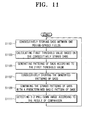
- Figure 11 is a flowchart showing a 3:2 pull-down image detecting method performed by the 3:2 pull-down main detection unit of Figure 3;
- Figure 12 is a flowchart showing a 3:2 pull-down image detecting method performed by the 3:2 pull-down sub-detection unit of Figure 3;
- Figure 13 is a flowchart showing a 2:2 pull-down image detecting method performed by the 2:2 pull-down main detection unit of Figure 3;
- Figure 14 is a flowchart showing a 2:2 pull-down image detecting method performed by the 2:2 pull-down sub-detection unit of Figure 3;
- Figures 15A to 15F are views showing examples of a bad-edit occurring in the 3:2 pull-down image to explain a bad-edit detecting method performed by the bad-edit detection unit of Figure 3; and
- Figures 16A to 16D are views showing examples of a bad-edit occurring in the 2:2 pull-down image to explain a bad-edit detecting method performed by the bad-edit detection unit of Figure 3.
-
- Referring to Figure 3, the video signal detecting apparatus includes a summed absolute difference (SAD) calculation unit 100, a pull-down
image detection unit 300, and a pull-downsequence decision unit 390. - The SAD calculation unit 100 includes a previous
field storage unit 103 for storing a previous field (n-1) which is input immediately before a currently-input video signal, a currentfield storage unit 105 for storing a currently-input field (n), and a nextfield storage unit 107 for storing a next field (n+1) which follows the current field (n). The SAD calculation unit 100 obtains pixel values with respect to the fields (n-1), (n), (n+1) stored in the previousfield storage unit 103, the currentfield storage unit 105, and the nextfield storage unit 107, respectively, and calculates a difference of the pixel values between the fields, i.e., calculates summed absolute differences (SADs). - The pull-down
image detection unit 300 includes a 3:2 pull-downmain detection unit 310, a 3:2 pull-downsub detection unit 330, a 2:2 pull-downmain detection unit 350, and a 2:2 pull-down sub-detection unit 370. The 3:2 pull-downmain detection unit 310 detects a 3:2 pull-down image based on a SAD between fields spaced from each other by one period. The 3:2 pull-downsub detection unit 330 detects a 3:2 pull-down image based on an absolute change amount (or absolute difference) with respect to the SAD between the fields spaced from each other by one period. Also, the 2:2 pull-downmain detection unit 350 detects a 2:2 pull-down image based on a SAD between consecutive fields. The 2:2 pull-down sub-detection unit 370 detects a 2:2 pull-down image based on an absolute difference with respect to the SAD between the consecutive fields. - The pull-down
sequence decision unit 390 includes a stillimage determining unit 393, a bad-edit detection unit 395, and adecision unit 397. The stillimage determining unit 393 determines if an input video signal is a still image based on the SADs and the absolute differences between the SADs calculated by the SAD calculation unit 100. The bad-edit detection unit 395 detects whether there occurs a bad-edit in the pull-down image detected by the 3:2 pull-downmain detection unit 310, the 3:2 pull-down sub-detection unit 330, the 2:2 pull-downmain detection unit 350, and the 2:2 pull-downsub detection unit 370, respectively. Thedecision unit 397 decides whether the video signal is a pull-down image or not based on the result of detecting the pull-down image by the pull-downimage unit 300, the result of determining the still image by the stillimage determining unit 393, and the result of detecting the occurrence of the bad-edit by the bad-edit judgment unit 395, respectively. - Referring to Figure 4, the 3:2 pull-down
main detection unit 310 includes aSAD calculation unit 313, aSAD storage unit 315, a first thresholdvalue calculation unit 317, a firstpattern generation unit 319, a firstpattern storage unit 321, and a firstpattern comparison unit 323. - The
SAD calculation unit 313 calculates a SAD between fields of the video signal which are spaced from each other by one period. In other words, the SAD calculation unit calculates a SAD between a previous field (n-1) of the input video signal and a next field (n+1). The calculation of SAD between the previous field (n-1) and the next field (n+1) by theSAD calculation unit 313 is repeatedly performed with respect to the fields of the consecutively input video signals. TheSAD storage unit 315 consecutively stores the SADs calculated by theSAD calculation unit 313. In order to consecutively store the calculated SADs, theSAD storage unit 315 is implemented by a predetermined number of FIFO (First-In First-Out) buffers. The first thresholdvalue calculation unit 317 calculates a first threshold value using the stored SADs. The firstpattern generation unit 319 generates patterns of the SADs according to the calculated first threshold value. The firstpattern storage unit 321 consecutively stores the patterns of the SADs generated by the firstpattern generation unit 319. In order to consecutively store the SAD patterns generated by the firstpattern generation unit 319, the firstpattern storage unit 321 is implemented by a predetermined number of FIFO buffers. The firstpattern comparison unit 323 compares the pattern of the SAD stored in the firstpattern storage unit 321 with a predetermined basic pattern of the SAD. - Also, the first threshold
value calculation unit 317 includes a first minimumvalue detection unit 317a and a first maximumvalue detection unit 317b (see Figure 5). The first minimumvalue detection unit 317a detects a minimum value of the continuous 5 SADs stored in theSAD storage unit 315. The first maximumvalue detection unit 317b detects a maximum value of 5 continuous SADs. In this case, since the SAD with respect to the fields of the 3:2 pull-down image has a minimum value once every 5 periods, the first minimumvalue detection unit 317a detects a minimum value once every 5 periods and thus can be implemented to reduce a load to the operations. - Also, the
sub-detection unit 330 includes an absolutedifference calculation unit 333, an absolutedifference storage unit 335, a second thresholdvalue calculation unit 337, a secondpattern generation unit 339, a secondpattern storage unit 341, and a secondpattern comparison unit 343. - The absolute
difference calculation unit 333 calculates an absolute difference between the SADs calculated by theSAD calculation unit 313. The absolutedifference storage unit 335 consecutively stores the calculated absolute differences. The second thresholdvalue calculation unit 337 calculates a second threshold value using the stored absolute differences. The secondpattern generation unit 339 generates patterns of the absolute differences according to the calculated second threshold value. The secondpattern storage unit 341 consecutively stores the patterns of the absolute differences generated by the secondpattern generation unit 339. In an exemplary embodiment, the absolutedifference storage unit 335 and the secondpattern storage unit 341 are implemented by FIFO buffers in the same manner as theSAD storage unit 315 and the firstpattern storage unit 321. - The second
pattern comparison unit 343 compares the pattern of the absolute difference stored in the secondpattern storage unit 341 with a predetermined basic absolute difference pattern. Also, the second thresholdvalue calculation unit 337 includes a second minimumvalue detection unit 337a and a second maximumvalue detection unit 337b (see Figure 6). The second minimumvalue detection unit 337a detects a minimum value of 5 continuous absolute differences stored in the absolutedifference storage unit 335. The second maximumvalue detection unit 337b detects a maximum value of the 5 continuous absolute differences. In an exemplary embodiment, the secondpattern storage unit 341 is implemented so that the absolute differences between the SADs stored in the firstpattern storage unit 321 are consecutively stored in the secondpattern storage unit 341. In this embodiment, the first thresholdvalue calculation unit 317 of the 3:2 pull-downmain detection unit 310 and the second thresholdvalue calculation unit 337 of the 3:2 pull-down sub-detection unit 330 detect the maximum value and the minimum value with respect to the 5 consecutive values only. This is because the basic pattern of the SADs and the absolute change amounts with respect to the 3:2 pull-down image has the 5 repeated consecutive values. However, this should not be considered as limiting because other numbers of values may be calculated. For instance, the first thresholdvalue calculation unit 317 of the 3:2 pull-downmain detection unit 310 and the second thresholdvalue calculation unit 337 of the 3:2 pull-downsub detection unit 330 may detect a minimum value and a maximum value from more than 5 consecutive values. - Figure 7 is a block diagram showing the 2:2 pull-down main detection unit and the 2:2 pull-down sub detection unit of FIG 3. Referring to Figure 7, the 2:2 pull-down
main detection unit 350 includes aSAD calculation unit 353, aSAD storage unit 355, a first thresholdvalue calculation unit 357, a firstpattern generation unit 359, a firstpattern storage unit 361, and a firstpattern comparison unit 363. - The
SAD calculation unit 353 calculates a SAD between consecutive fields of a video signal. In other words, theSAD calculation unit 353 calculates a SAD between a previous field (n-1) and a current field (n) with respect to a video signal. TheSAD storage unit 355 consecutively stores the SADs calculated by theSAD calculation unit 353. In order to consecutively store the calculated SADs, theSAD storage unit 355 is implemented as a predetermined number of FIFO buffers. The first thresholdvalue calculation unit 357 calculates a first threshold value using the stored SADs. The firstpattern generation unit 359 generates patterns of the SADs according to the calculated first threshold value. The firstpattern storage unit 361 consecutively stores the patterns of the SADs generated by the firstpattern generation unit 359. In order to consecutively store the SAD patterns generated by the firstpattern generation unit 359, the firstpattern storage unit 361 is implemented by a predetermined number of FIFO buffers. The firstpattern comparison unit 363 compares the pattern of the SAD stored in the firstpattern storage unit 361 with a predetermined basic pattern of the SAD. - Also, the first threshold
value calculation unit 357 includes a first minimumvalue detection unit 357a and a first maximumvalue detection unit 357b (see Figure 8). - The first minimum
value detection unit 357a detects a minimum value of the SADs with respect to a specified section of the SADs stored in theSAD storage unit 355. The first maximumvalue detection unit 357b detects a maximum value of the SADs with respect to the specified section. In this case, since the 2:2 pull-down sequence has the minimum value of the SADs between two fields of the same frame and has the maximum value of the SADs between consecutive fields of two adjacent frames, the first minimumvalue detection unit 357a and the first maximumvalue detection unit 357b can be implemented to detect the minimum value and the maximum value with respect to the SADs between the spaced fields. In an exemplary embodiment, the first minimumvalue detection unit 357a and the first maximumvalue detection unit 357b are implemented so that the first minimumvalue detection unit 357a detects the SAD between the fields of the same frame, and the first maximumvalue detection unit 357b detects the SAD between the fields of the adjacent frames. - Also, the
sub-detection unit 370 includes an absolutedifference calculation unit 373, an absolutedifference storage unit 375, a second thresholdvalue calculation unit 377, a secondpattern generation unit 379, a secondpattern storage unit 381, and a secondpattern comparison unit 383. The absolutedifference calculation unit 373 calculates an absolute difference between the SADs calculated by theSAD calculation unit 353. The absolutedifference storage unit 375 consecutively stores the calculated absolute differences. The second thresholdvalue calculation unit 377 calculates a second threshold value using the stored absolute differences. The secondpattern generation unit 379 generates patterns of the absolute differences according to the calculated second threshold value. The secondpattern storage unit 381 consecutively stores the patterns of the absolute differences generated by the secondpattern generation unit 379. In an exemplary embodiment, the absolutedifference storage unit 375 and the secondpattern storage unit 381 are implemented by FIFO buffers in the same manner as theSAD storage unit 355 and the firstpattern storage unit 361. - The second
pattern comparison unit 383 compares the pattern of the absolute difference stored in the secondpattern storage unit 381 with a predetermined basic pattern of the absolute difference. Also, the second threshold value calculation unit 387 includes a second minimumvalue detection unit 377a and a second maximumvalue detection unit 377b (see Figure 9) The second minimumvalue detection unit 377a detects a minimum value of the absolute differences with respect to a specified section of the absolute differences stored in the absolutedifference storage unit 375. The second maximumvalue detection unit 377b detects a maximum value of the absolute differences with respect to the specified section. In an exemplary embodiment, the secondpattern storage unit 381 is implemented so that the absolute differences between the SADs stored in the firstpattern storage unit 361 are consecutively stored in the secondpattern storage unit 381. - With reference to the drawings, the operation of the video signal detecting apparatus according to the present invention will be described in greater detail hereinbelow.
- Referring to Figure 10, the SAD calculation unit 100 obtains pixel values of fields stored in the previous field storage unit, the current field storage unit, and the next field storage unit and calculates differences of the pixel values between the fields, i.e., SAD between the previous field (n-1) and the current field (n), SAD between the current field (n) and the next field (n+1), and SAD between the previous field (n-1) and the next field (n+1) (S1010). The pull-down
image detection unit 300 detects a pull-down image with respect to an input video signal based on the calculated SADs (S1020). The pull-down image detection process performed by the pull-downimage detection unit 300 is divided into a 3:2 pull-down image detection process and a 2:2 pull-down image detection process. - The still
image determining unit 393 determines whether the input video signal is a still image based on the calculated SADs and the absolute differences between the SADs (S1030). For example, if it is defined that the difference of pixel values between the previous field (n-1) and the current field (n) is SAD1 and the difference of pixel values between the current field (n) and the next field (n+1) is SAD2, the absolute difference between the SADs is an absolute difference value of pixel values between the SAD1 and SAD2. - The bad-
edit detection unit 395 detects whether there occurs a bad-edit in an editing process with respect to the input video signal (S1040). The detection by the bad-edit detection unit 395 will be described in detail later. - The pull-down
sequence decision unit 390 decides the video signal as a pull-down image according to the combination of the result of detecting a pull-down image by the 3:2 pull-downmain detection unit 310, the 3:2 pull-down sub-detection unit 330, the 2:2 pull-downmain detection unit 350, and the 2:2 pull-down sub-detection unit 370 of the pull-downimage detection unit 300, the result of detecting a still image by the stillimage determining unit 393, and the result of detecting the occurrence of the bad-edit by the bad-edit detection unit 395, respectively (S1050). The method of detecting a pull-down image of a video signal performed by the pull-downsequence decision unit 390 will be described later. - Referring to Figure 11, the
SAD calculation unit 313 calculates a SAD between one period-spaced fields, i.e., a SAD between the previous field (n-1) and the next field (n+1). TheSAD storage unit 315 consecutively stores the SADs calculated by the SAD calculation unit 313 (S1101). The first thresholdvalue calculation unit 317 calculates a first threshold value by using the SADs consecutively stored in theSAD storage unit 315. The first minimumvalue detection unit 317a of the firstthreshold calculation unit 317 detects a minimum value of 5 continuous SADs stored in theSAD storage unit 315. Since a 3:2 pull-down image has one same field for 5 fields, the first minimumvalue detection unit 317a may be implemented so as to detect the minimum value only once for 5 fields. Also, the first maximumvalue detection unit 317b of the first thresholdvalue calculation unit 317 detects a maximum value of 5 continuous SADs stored in theSAD storage unit 315. The first thresholdvalue calculation unit 317 calculates the first threshold value based on the minimum value and the maximum value of the SADs detected by the first minimumvalue detection unit 317a and the first maximumvalue detection unit 317b, and the calculation of the first threshold value is performed in accordance with the following equation. - Here, T1 denotes the first threshold value of a pull-down image field, a and b are certain values ensuring a + b = 1, MIN denotes the minimum value of the 5 continuous SADs, and MAX denotes the maximum value of the continuous 5 SADs.
- The first
pattern generation unit 319 generates patterns of the SADs stored in theSAD storage unit 315 according to the first threshold value calculated by the first threshold value calculation unit 317 (step S1105). The firstpattern generation unit 319 compares the SAD with the first threshold value calculated by the first thresholdvalue calculation unit 317, and generates '1' if the SAD is larger than the first threshold value. Otherwise, the firstpattern generation unit 319 generates '0'. - The first
pattern storage unit 321 consecutively stores the patterns of the SADs generated by the first pattern generation unit 309 (S1107). The firstpattern comparison unit 323 compares the pattern of the SAD stored in the firstpattern storage unit 321 with the predetermined basic pattern of the SAD (step S1109). Here, the basic pattern of the SAD means the basic pattern of the SAD of the 3:2 pull-down image, and may take the form of five possible patterns. The five types of the basic pattern of the SAD are 0111101111, 1011110111, 1101111011, 1110111101, and 1111011110. The 3:2 pull-downmain detection unit 310 detects the 3:2 pull-down image according to a result of comparison by the first pattern comparison unit 323 (step S1111). In other words, if the pattern of the SAD stored in the firstpattern storage unit 321 is identical to the basic pattern of the SAD, the 3:2 pull-downmain detection unit 310 decides the input video signal to be a 3:2 pull-down image. This process of detecting the 3:2 pull-down image is repeatedly performed with respect to the input image signal. In the case that the picture is abruptly changed (for instance with a scene cut), the 3:2 pull-down image is still detected by adaptively changing the threshold value, thus properly cop ing with the changed picture. - Referring to Figure 12, the absolute
difference calculation unit 333 calculates an absolute difference between SADs calculated by theSAD calculation unit 313 of the 3:2 pull-downmain detection unit 310 between one period-spaced fields. In other words, if it is defined that the difference of pixel values between the previous field (n-1) and the next field (n+1) is SAD3 and the difference of pixel values between the current field n and the next field (n+2) is SAD4, the absolutedifference calculation unit 333 calculates an absolute difference value between SAD3 and SAD4. The absolutedifference storage unit 335 consecutively stores the absolute differences calculated by the absolute difference calculation unit 333 (S1201). The second thresholdvalue calculation unit 337 calculates a second threshold value by using the absolute difference stored in the absolute difference storage unit 335 (S1203). The second minimumvalue detection unit 337a of the second thresholdvalue calculation unit 337 detects a minimum value with respect to 5 continuous absolute differences from the absolute differences stored in the absolutedifference storage unit 335. Also, the second thresholdvalue calculation unit 337 detects a maximum value with respect to the 5 continuous absolute differences from the absolute differences stored in the absolutedifference storage unit 335. The second thresholdvalue calculation unit 337 calculates a second threshold value based on the minimum value and the maximum value of the absolute differences detected by the second minimumvalue detection unit 337a and the second maximumvalue detection unit 337b. The calculation of the second threshold value is performed by the following equation. - Here, T2 denotes the second threshold value with respect to the field of the 3:2 pull-down image, a' and b' are certain values ensuring a' + b' = 1, MIN' denotes the minimum value of the 5 continuous absolute differences, and MAX' denotes the maximum value of the 5 continuous absolute differences.
- The second
pattern generation unit 339 generates patterns of the absolute differences stored in the absolutedifference storage unit 335 according to the second threshold value calculated by the second threshold value calculation unit 337 (step S1205). In this case, the secondpattern generation unit 339 compares the absolute difference with the second threshold value calculated by the second thresholdvalue calculation unit 337, and generates '1' if the absolute difference is larger than the second threshold value. Otherwise, the secondpattern generation unit 359 generates '0'. - The second
pattern storage unit 341 consecutively stores the patterns of the absolute differences generated by the second pattern generation unit 339 (step S1207). The secondpattern comparison unit 343 compares the pattern of the absolute difference stored in the secondpattern storage unit 341 with the predetermined basic pattern of the absolute difference (step S1209). The basic pattern of the absolute difference means the basic pattern of the absolute difference of the 3:2 pull-down image, and may take the form of five possible patterns. The five types of the basic pattern of the absolute change amount are 1000110001, 1100011000, 0110001100, 0011000110, and 0001100011. The 3:2 pull-downsub detection unit 330 detects a 3:2 pull-down image according to a result of comparison by the secondpattern comparison unit 343. In other words, if the pattern of the absolute difference stored in the secondpattern storage unit 341 is identical to the basic pattern, the 3:2 pull-down detection unit 330 decides that the input image signal is a 3:2 pull-down image. - Referring to Figure 13, the
SAD calculation unit 353 calculates SADs between consecutive fields, i.e., a SAD between the previous field (n-1) and the current field (n) and a SAD between the current field (n) and the next field (n+1). TheSAD storage unit 355 consecutively stores the SADs calculated by the SAD calculation unit 353 (S1301). The first thresholdvalue calculation unit 357 calculates a first threshold value by using the SADs consecutively stored in the SAD storage unit 355 (S1303). In this case, the first minimumvalue detection unit 357a of the first thresholdvalue calculation unit 357 detects a minimum value of the SADs with respect to a specified section of the SADs stored in theSAD storage unit 355. The first maximumvalue detection unit 357b of the first thresholdvalue calculation unit 357 detect a maximum value of the SADs with respect to the specified section of the SADs stored in theSAD storage unit 355. Since it is generally the case that the SAD between the fields of the same frame has a small value, the first minimumvalue detection unit 357a may be implemented so as to detect the minimum value by searching for only the SAD between the fields of the same frame. Also, since it is generally the case that the SAD between the fields of the adjacent frames is changed (which may mean they are large), the first maximumvalue detection unit 357b may be implemented so as to detect the maximum value by searching for only the SAD between the fields of the adjacent frames. - The first threshold
value calculation unit 357 calculates the first threshold value based on the minimum value and the maximum value of the SADs detected by the first minimumvalue detection unit 357a and the first maximumvalue detection unit 357b. The calculation of the first threshold value is performed by the following equation. - Here, T3 denotes the first threshold value with respect to the field of the 2:2 pull-down image, c and d are certain values ensuring c + d = 1, MIN denotes the minimum value of the SADs in a specified section, and MAX denotes the maximum value of the SADs in the specified section.
- The first
pattern generation unit 359 generates patterns of the SADs stored in theSAD storage unit 355 according to the first threshold value calculated by the first threshold value calculation unit 357 (step S1305). In this case, the firstpattern generation unit 359 compares the SAD with the first threshold value calculated by the first thresholdvalue calculation unit 357, and generates '1' if the SAD is larger than the first threshold value. Otherwise, the first pattern generation unit 309 generates '0'. - The first
pattern storage unit 361 consecutively stores the patterns of the SADs generated by the first pattern generation unit 359 (step S1307). The firstpattern comparison unit 363 compares the pattern of the SAD stored in the firstpattern storage unit 361 with the predetermined basic pattern of the SAD (step S1309). Here, the basic pattern of the SAD means the basic pattern of the SAD of the 2:2 pull-down image, and may take the form of two combinations of basic pattern. The two types of the basic pattern of the SAD are 0101010101 and 1010101010. The 2:2 pull-downmain detection unit 350 detects the 2:2 pull-down image according to a result of comparison by the first pattern comparison unit 363 (step S1311). In other words, if the pattern of the SAD stored in the firstpattern storage unit 361 is identical to the basic pattern of the SAD, the 2:2 pull-downmain detection unit 350 decides that the input image signal is a 2:2 pull-down image. The process of detecting the 2:2 pull-down image is repeatedly performed with respect to the input image signal. In the case that the picture is abruptly changed (for example, a scene change), the 2:2 pull-down image is detected by adaptively changing the threshold value. This means that it can properly cope with the changed picture. - Referring to Figure 14, the absolute
difference calculation unit 373 of the 2:2 pull-down sub-detection unit 370 calculates the absolute difference between the SADs calculated by the SAD calculation unit of the 2:2 pull-downmain detection unit 350. That is, the absolutedifference calculation unit 373 calculates an absolute difference between SADs calculated between the previous field (n-1) and the current field (n) and between the current field (n) and the next field (n+1). The absolutedifference storage unit 375 consecutively stores the absolute differences calculated by the absolute difference calculation unit 373 (S1401). The second thresholdvalue calculation unit 377 calculates a second threshold value by using the absolute differences consecutively stored in the absolute difference storage unit 375 (S1403). In this case, the second minimumvalue detection unit 377a detects the minimum value of the absolute differences with respect to a specified section of the absolute differences stored in the absolutedifference storage unit 375. Also, the second maximumvalue detection unit 377b of the second thresholdvalue calculation unit 377 detects the maximum value of the absolute differences with respect to the specified section of the absolute differences stored in the absolutedifference storage unit 375. - The second threshold
value calculation unit 377 calculates the second threshold value based on the minimum value and the maximum value of the absolute differences detected by the second minimumvalue detection unit 377a and the second maximumvalue detection unit 377b. The calculation of the second threshold value is in accordance with the following equation. - Here, T4 denotes the second threshold value with respect to the field of the 2:2 pull-down image, c' and d' are certain values ensuring c' + d' = 1, MIN' denotes the minimum value of the absolute differences in a specified section, and MAX' denotes the maximum value of the absolute differences in the specified section.
- The second
pattern generation unit 379 generates patterns of the absolute differences stored in the absolutedifference storage unit 375 according to the second threshold value calculated by the second threshold value calculation unit 377 (step S1405). In this case, the secondpattern generation unit 379 compares the absolute difference with the second threshold value calculated by the second thresholdvalue calculation unit 377, and generates '1' if the absolute difference is larger than the second threshold value. Otherwise, the secondpattern generation unit 359 generates '0'. In the drawing, '+' is marked instead of '1', and '-' instead of '0'. - The second
pattern storage unit 381 consecutively stores the patterns of the absolute differences generated by the second pattern generation unit 379 (step S1407). The secondpattern comparison unit 383 compares the pattern of the absolute difference stored in the secondpattern storage unit 381 with the predetermined basic pattern of the absolute difference (step S1409). Here, the basic pattern of the absolute difference means the basic pattern of the absolute difference of the 2:2 pull-down image, and may take the form of two combinations. The two types of the basic pattern of the absolute change amount are -+-+-+-+-+ and +-+-+-+-+-. - The
sub-detection unit 370 detects the 2:2 pull-down image according to a result of comparison by the second pattern comparison unit 383 (step S1411). In other words, if the pattern of the absolute difference stored in the secondpattern storage unit 381 is identical to the basic pattern of the absolute difference, the 2:2 pull-down sub-detection unit 370 decides that the input image signal is the 2:2 pull-down image. - Figures 15A to 15F show examples of bad-edit occurring in the 3:2 pull-down image, to explain a bad-edit detection method of the bad-edit detection unit of Figure 3.
- If a normal image signal of 3:2 pull-down image, i.e., having no bad-edit, is input, the SAD in the 3:2 pull-down
main detection unit 310 appears in the pattern of 0111101111. Meanwhile, the SAD in the 2:2 pull-downmain detection unit 350 appears in the patterns of OXOXOXOXOX or XOXOXOXOXO. The pattern of SAD in the 3:2 pull-downmain detection unit 310 and the pattern of SAD in the 2:2 pull-downmain detection unit 350 are shown differently for the convenience of explanation. - If there occurs a bad-edit in which a field is omitted from the frame A, the pattern of SAD in the 3:2 pull-down
main detection unit 310 becomes 1. Also, all of the patterns of the SADs in the 2:2 pull-downmain detection unit 350 become 'x'. In other words, the pattern of SAD between the current field C and the next field N and the pattern of SAD between the current field C and the previous field P all become 'x'. With respect to the bottom field of the frame B, the pattern of SAD between the current field C and the next field N becomes 'x' and the pattern of SAD of the current field C and the previous field P becomes 'o', while the pattern of SAD between the previous field P and the next field N becomes 1. These patterns deviate from the basic pattern of the SAD, and this means that there occurs a bad-edit in the 3:2 pull-down image. Several examples of the bad-edit occurrences are illustrated Figures 15B to 15F. - Referring to Figure 16, in the normal 2:2 pull-down image signal without the bad-edit, the pattern of SAD between the current field C and the next field N and the pattern of SAD between the current field C and the previous field N appear alternately (see Figure 16A).
- If there occurs a bad-edit in which the bottom field is omitted from the frame C, the pattern of SAD between the current field C and the next field N and the pattern of SAD between the current field C and the previous field P all become 'x'. These patterns deviate from the basic pattern of the SAD of the 2:2 pull-down image, and this means that there occurs a bad-edit in the 2:2 pull-down image. Several examples of the bad-edit occurrences are illustrated in Figures 16B to 16D.
- As described above, the bad-
edit detection unit 395 detects whether a bad-edit has occurred in the 3:2 pull-down image or the 2:2 pull-down image by searching the patterns of SADs and the patterns of the absolute differences, which are detected by the 3:2 pull-downmain detection unit 310, 3:2 pull-down sub-detection unit 330, 2:2 pull-downmain detection unit 350 and the 2:2 pull-down sub-detection unit 370, respectively. - The still
image determining unit 393 determines whether the input image signal is a still image based on the SAD and the absolute difference. For example, if the presently calculated SAD and the SAD calculated one field before are very small in comparison to the previous SAD and the absolute difference between the presently calculated SAD and the SAD calculated one field before is very small in comparison to the previous absolute difference, the present input image is close to a still image. The pattern of the SAD and the pattern of the absolute difference stored in the firstpattern storage unit 321 and the secondpattern storage unit 381 are as follows.
SAD_pattern[n-1] = 0
SAD_pattern[n] = 0
|Δ SAD|_pattern[n-1] =0 - The
decision unit 397 decides whether the input image signal is the 3:2 pull-down sequence or the 2:2 pull-down sequence by combining results of detecting the 3:2 pull-down image by the 3:2 pull-downmain detection unit 310, the 3:2 pull-down sub-detection unit 330, the 2:2 pull-downmain detection unit 350, and the 2:2 pull-down sub-detection unit 370, a result of determining whether the image signal is the still image by the stillimage determining unit 390, and a result of detecting whether there occurs a bad-edit by the bad-edit detection unit 395. Several examples of deciding the pull-down sequence by thedecision unit 390 are shown in Table 1 below.Decision Previous Flag Still Flag Bad-edit Flag 3:2 Main 3:2 Sub 2:2 Main 2:2 Sub Count 0 0 X X 1 1 X X count < ε 1 X X X 1 1 X X count = ε 0 0 X X 1 0 1 0 X 1 1 X X 1 0 1 0 X 1 1 0 X 0 1 1 1 X 1 1 0 1 0 0 0 0 X - If it is determined that the image signal is the 3:2 pull-down image by the 3:2 pull-down
main detection unit 310 and the 3:2 pull-down sub-detection unit 330, and the 3:2 pull-down image does not continue for a predetermined time, thedecision unit 397 decides that the image signal is not actually the pull-down sequence irrespective of the previous flag, the still flag, and the bad-edit flag. However, if the 3:2 pull-down image continues for a predetermined time, thedecision unit 397 decides the image signal to be the 3:2 pull-down sequence in accordance with the result of detecting the 3:2 pull-down image by the 3:2 pull-downmain detection unit 310 and the 3:2 pull-down sub-detection unit 330. - If the 3:2 pull-down
main detection unit 310 and the 2:2 pull-down main-detection unit 350 detect the 3:2 pull-down image and the 2:2 pull-down image respectively, where the previous flag is "0', thedecision unit 397 will decide the image signal to be the pull-down image whilst maintaining the previous flag. - If the 3:2 pull-down
main detection unit 310, the 3:2 pull-down sub-detection unit 330, the 2:2 pull-downmain detection unit 350, and the 2:2 pull-down sub-detection unit 370 do not detect the pull-down image and the bad-edit detection unit 395 detects the bad-edit where the previous flag is "1", thedecision unit 397 decides the image signal to be the pull-down sequence and maintains the previous flag. Here, the fact that the previous flag is "0" means that the 3:2 pull-down image is not decided with respect to the previous image signal. - Consequently, the image signal detecting apparatus according to the present invention can accurately detect the pull-down image by detecting the 3:2 pull-down image and the 2:2 pull-down image using the SAD and the absolute change amount. Also, the apparatus can prevent the displayed image from appearing unnatural by reducing the frequency of on/off operations of the pull-down image flag.
- Also, as described above, since the image signal detecting apparatus detects the bad-edit by the bad-edit detection unit, and detects the image signal according to the detect result, compensation with respect to the image signal is achieved.
Claims (23)
- A method of detecting a bad-edit portion of a television signal, characterised by:generating a difference signal indicative of a difference between two fields;generating a telecine portion indication signal in accordance with the difference signal; andgenerating a bad-edit indication signal indicative of a bad-edit in the frame generated in accordance with the difference signal.
- A method according to claim 1, comprising:generating an absolute difference signal indicative of the magnitude of the difference between two difference signals; andgenerating the bad-edit indication signal in accordance with the absolute difference signal.
- A method according to claim 2, comprising:comparing a pattern of generated absolute difference signals over a period with at least one predetermined pattern; andgenerating the telecine portion indication signal in accordance with the comparison of the pattern.
- A method according to any one of claims 1-3, comprising:comparing a pattern of generated difference signals over a period with at least one predetermined pattern; andgenerating the telecine portion indication signal in accordance with the comparison of the pattern.
- An apparatus for detecting a bad-edit portion of a television signal, characterised by:means (300) for generating a difference signal indicative of a difference between two fields and;means (397) for generating a telecine portion indication signal in accordance with the difference signal; andmeans (395) for generating a bad-edit indication signal indicative of a bad-edit in the frame generated in accordance with the difference signal.
- An apparatus according to claim 5, comprising:means (370) for generating an absolute difference signal indicative of the magnitude of the difference between two difference signals; andmeans (395) for generating the bad-edit indication signal in accordance with the absolute difference signal.
- An apparatus according to claim 6, comprising:means (343) for comparing a pattern of generated absolute difference signals over a period with at least one predetermined pattern; andmeans (395) for generating the telecine portion indication signal in accordance with the comparison of the pattern.
- An apparatus according to any one of claims 5-7, comprising:means (323) for comparing a pattern of generated difference signals over a period with at least one predetermined pattern; andmeans (395) for generating the telecine portion indication signal in accordance with the comparison of the pattern.
- A television comprising:display means for displaying a picture; andan apparatus according to any one of claims 5-8.
- An image signal detecting apparatus, comprising:a SAD calculation unit for calculating summed absolute differences (SADs) among a current field (n), a previous field (n-1), and a next field (n+1) with respect to consecutively input image signals with 'n' being n=1, 2, 3,...;a pull-down image detection unit for detecting a pull-down image based on the calculated SADs;a still image determining unit for determining whether the input image signal is a still image or not based on the calculated SADs and absolute change amounts among the SADs;a bad-edit detection unit for detecting a bad-edit in the detected pull-down image; anda decision unit for deciding whether the input image signal is the pull-down image or not based on the result of detecting the pull-down image, the result of determining whether the input image signal is a still image by the still image judgment unit, and the result of detecting the occurrence of the bad-edit.
- The image signal detecting apparatus of claim 10, wherein the pull-down image detection unit comprises:a 3:2 pull-down image detection unit for detecting a 3:2 pull-down image; anda 2:2 pull-down image detection unit for detecting a 2:2 pull-down image.
- The image signal detecting apparatus of claim 11, wherein the 3:2 pull-down image detection unit comprises:a main detection unit for detecting the 3:2 pull-down image based on a SAD between fields spaced from each other by 1 period; anda sub detection unit for detecting the 3:2 pull-down image based on an absolute change amount with respect to the SAD between the 1 period-spaced fields.
- The image signal detecting apparatus of claim 12, wherein the 3:2 pull-down image detection unit detects the 3:2 pull-down image by generating patterns of the SADs between the 1 period-spaced fields and patterns of the absolute change amounts, and comparing the patterns of the SADs and the patterns of the absolute change amounts with a basic pattern of the 3:2 pull-down image.
- The image signal detecting apparatus of claim 11, wherein the 2:2 pull-down image detection unit comprises:a main detection unit for detecting the 2:2 pull-down image based on a SAD between consecutive fields; anda sub-detection unit for detecting the 2:2 pull-down image based on an absolute change amount with respect to the SAD between the consecutive fields.
- The image signal detecting apparatus of claim 14, wherein the 2:2 pull-down image detection unit detects the 2:2 pull-down image by generating patterns of the SADs between the consecutive fields and patterns of the absolute change amounts, and comparing the patterns of the SADs and the patterns of the absolute change amounts with a basic pattern of the 2:2 pull-down image.
- An image signal detecting method comprising:a SAD calculating step of calculating SADs among a current field (n), a previous field (n-1), and a next field (n+1) with respect to consecutively input image signals with 'n' being n=1, 2,3,...;a pull-down image detection step of detecting a pull-down image based on the calculated SADs;a still image judgment step of judging whether the input image signal is a still image based on the calculated SADs and absolute change amounts among the SADs;a bad-edit detection step of detecting a bad-edit in the detected pull-down image; anda pull-down image decision step of deciding whether the input image signal is the pull-down image or not based on the result of detecting the pull-down image, the result of judging whether the input image signal is a still image by the still image judgment step, and the result of detecting the occurrence of the bad-edit.
- The image signal detecting method of claim 16, wherein the pull-down image detection step comprises:a 3:2 pull-down image detection step of detecting a 3:2 pull-down image; anda 2:2 pull-down image detection step of detecting a 2:2 pull-down image.
- The image signal detecting method of claim 17, wherein the 3:2 pull-down image detection step comprises:a main detection step of detecting the 3:2 pull-down image based on a SAD between fields spaced from each other by 1 period; anda sub-detection step of detecting the 3:2 pull-down image based on an absolute change amount with respect to the SAD between the 1 period-spaced fields.
- The image signal detecting method of claim 17, wherein the 2:2 pull-down image detection step comprises:a main detection step of detecting the 2:2 pull-down image based on a SAD between consecutive fields; anda sub-detection step of detecting the 2:2 pull-down image based on an absolute change amount with respect to the SAD between the consecutive fields.
- The image signal detecting method of 18, wherein the main detection step comprises:consecutively storing the SADs between the 1 period-spaced fields;calculating a first threshold value using the consecutively stored SADs;generating patterns of the SADs according to the calculated first threshold value;consecutively storing the patterns of the SADs; andcomparing the stored patterns of the SADs with a predetermined basic pattern of the SAD, andthe main detection step detects the 3:2 pull-down image according to the result of the comparison by the SAD pattern comparison step.
- The image signal detecting method of claim 18, wherein the sub-detection step comprises:wherein the sub detection step detects the 3:2 pull-down image according to the result of the comparison by the absolute change amount pattern comparison step.consecutively storing absolute change amounts with respect to the SADs between the 1 period-spaced fields;calculating a second threshold value using the consecutively stored absolute change amounts;generating patterns of the absolute change amounts according to the calculated second threshold value;consecutively storing the patterns of the absolute change amounts; andcomparing the patterns of the stored absolute change amounts with a predetermined basic pattern of the absolute change amounts,
- The image signal detecting method of 19, wherein the main detection step comprises:wherein the main detection step detects the 2:2 pull-down image according to the result of the comparison by the SAD pattern comparison step.consecutively storing the SADs between consecutive fields;calculating a first threshold value using the consecutively stored SADs;generating patterns of the SADs according to the calculated first threshold value;consecutively storing the patterns of the SADs; andcomparing the stored patterns of the SADs with a predetermined basic pattern of the SAD,
- The image signal detecting method of claim 19, wherein the sub-detection step comprises:wherein the sub-detection step detects the 2:2 pull-down image according to the result of the comparison by the absolute change amount pattern comparison step.consecutively storing absolute change amounts with respect to the SADs between the consecutive fields;calculating a second threshold value using the consecutively-stored absolute change amounts;generating patterns of the absolute change amount according to the calculated second threshold value;consecutively storing the patterns of the absolute change amounts; andcomparing the patterns of the stored absolute change amounts with a predetermined basic pattern of the absolute change amount,
Applications Claiming Priority (2)
| Application Number | Priority Date | Filing Date | Title |
|---|---|---|---|
| KR1020030049909A KR20050011069A (en) | 2003-07-21 | 2003-07-21 | Video signal detecting apparatus and a method for removing comb by bad-edit |
| KR2003049909 | 2003-07-21 |
Publications (2)
| Publication Number | Publication Date |
|---|---|
| EP1501298A1 true EP1501298A1 (en) | 2005-01-26 |
| EP1501298B1 EP1501298B1 (en) | 2006-08-02 |
Family
ID=36915021
Family Applications (1)
| Application Number | Title | Priority Date | Filing Date |
|---|---|---|---|
| EP20040102871 Expired - Lifetime EP1501298B1 (en) | 2003-07-21 | 2004-06-22 | Method and apparatus of identifying a telecine portion and bad-edits in a video sequence |
Country Status (6)
| Country | Link |
|---|---|
| US (1) | US20050018086A1 (en) |
| EP (1) | EP1501298B1 (en) |
| JP (1) | JP2005045808A (en) |
| KR (1) | KR20050011069A (en) |
| CN (1) | CN100450194C (en) |
| DE (1) | DE602004001722T2 (en) |
Cited By (2)
| Publication number | Priority date | Publication date | Assignee | Title |
|---|---|---|---|---|
| WO2008083249A1 (en) | 2006-12-27 | 2008-07-10 | Intel Corporation | A method and system for telecine detection and restoration |
| EP1990991A1 (en) * | 2007-05-09 | 2008-11-12 | British Telecommunications Public Limited Company | Video signal analysis |
Families Citing this family (12)
| Publication number | Priority date | Publication date | Assignee | Title |
|---|---|---|---|---|
| KR20050011067A (en) * | 2003-07-21 | 2005-01-29 | 삼성전자주식회사 | Apparatus and a method for detecting 2:2 pull-down sequence |
| KR20050011068A (en) * | 2003-07-21 | 2005-01-29 | 삼성전자주식회사 | Apparatus and a method for detecting film mode |
| US7460180B2 (en) * | 2004-06-16 | 2008-12-02 | Realtek Semiconductor Corp. | Method for false color suppression |
| TWI257811B (en) * | 2004-08-16 | 2006-07-01 | Realtek Semiconductor Corp | De-interlacing method |
| US7280159B2 (en) * | 2004-06-16 | 2007-10-09 | Realtek Semiconductor Corp. | Method and apparatus for cross color and/or cross luminance suppression |
| CN100352261C (en) * | 2005-06-09 | 2007-11-28 | 西安交通大学 | Detection method of 3:2 pull-down film source video |
| US7551232B2 (en) * | 2005-11-14 | 2009-06-23 | Lsi Corporation | Noise adaptive 3D composite noise reduction |
| US20070296855A1 (en) * | 2006-06-22 | 2007-12-27 | Yunwei Jia | Video processing using region-based statistical measurements |
| KR20080068464A (en) * | 2007-01-19 | 2008-07-23 | 삼성전자주식회사 | Apparatus and method for estimating an image signal noise, and apparatus and method for image signal conversion using thereof |
| CN101087439B (en) * | 2007-07-03 | 2010-09-08 | 华为技术有限公司 | A method, device and display for detecting TV and film signals |
| WO2009155979A1 (en) * | 2008-06-26 | 2009-12-30 | Telefonaktiebolaget Lm Ericsson (Publ) | Detecting repetition in digital video |
| JP5206313B2 (en) * | 2008-10-27 | 2013-06-12 | 富士通株式会社 | COMBING NOISE DETECTION DEVICE AND COMBING NOISE DETECTION METHOD |
Citations (2)
| Publication number | Priority date | Publication date | Assignee | Title |
|---|---|---|---|---|
| WO1997039577A1 (en) * | 1996-04-12 | 1997-10-23 | Snell & Wilcox Limited | Processing of video signals prior to compression |
| US6509933B1 (en) * | 1999-05-25 | 2003-01-21 | Pioneer Corporation | Video signal converting apparatus |
Family Cites Families (20)
| Publication number | Priority date | Publication date | Assignee | Title |
|---|---|---|---|---|
| KR0137702B1 (en) * | 1994-12-13 | 1998-05-15 | 양승택 | Film mode image signal detection apparatus |
| KR960028124A (en) * | 1994-12-30 | 1996-07-22 | 이몬 제이. 월 | Method and apparatus for identifying video fields generated by film sources |
| US5563651A (en) * | 1994-12-30 | 1996-10-08 | Thomson Consumer Electronics, Inc. | Method and apparatus for identifying video fields produced by film sources employing 2-2 and 3-2 pull down sequences |
| US5864368A (en) * | 1995-02-28 | 1999-01-26 | Sony Corporation | Picture signal editing and encoding method and apparatus, signal recording medium and picture signal decoding method and apparatus |
| JP3903498B2 (en) * | 1996-07-25 | 2007-04-11 | 三菱電機株式会社 | Video signal conversion method and video signal converter |
| KR100436649B1 (en) * | 1996-12-20 | 2004-09-08 | 소니 일렉트로닉스 인코포레이티드 | Method and apparuatus for changing phase of video program material taken from 24 frame per second film |
| JP3523026B2 (en) * | 1997-09-04 | 2004-04-26 | 三菱電機株式会社 | Image signal processing device |
| JPH11261961A (en) * | 1998-03-10 | 1999-09-24 | Toshiba Corp | Moving image processor |
| BE1012172A5 (en) * | 1998-09-15 | 2000-06-06 | Barco Naanloze Vennootschap | Method and apparatus for video processing. |
| US6392712B1 (en) * | 2000-03-31 | 2002-05-21 | Intel Corporation | Synchronizing interlaced and progressive video signals |
| US6867814B2 (en) * | 2000-04-18 | 2005-03-15 | Silicon Image, Inc. | Method, system and article of manufacture for identifying the source type and quality level of a video sequence |
| US6771795B1 (en) * | 2000-09-07 | 2004-08-03 | Sarnoff Corporation | Spatio-temporal channel for image watermarks or data |
| US6839094B2 (en) * | 2000-12-14 | 2005-01-04 | Rgb Systems, Inc. | Method and apparatus for eliminating motion artifacts from video |
| US7202907B2 (en) * | 2002-04-09 | 2007-04-10 | Zoran Corporation | 2:2 and 3:2 pull-down detection techniques |
| KR100902315B1 (en) * | 2002-07-25 | 2009-06-12 | 삼성전자주식회사 | Apparatus and method for deinterlacing |
| KR20040054032A (en) * | 2002-12-16 | 2004-06-25 | 삼성전자주식회사 | Format detection apparatus and method of image signal |
| US7050088B2 (en) * | 2003-01-06 | 2006-05-23 | Silicon Integrated Systems Corp. | Method for 3:2 pull-down film source detection |
| US7075581B1 (en) * | 2003-06-03 | 2006-07-11 | Zoran Corporation | Interlaced-to-progressive scan conversion based on film source detection |
| KR20050011068A (en) * | 2003-07-21 | 2005-01-29 | 삼성전자주식회사 | Apparatus and a method for detecting film mode |
| KR20050011067A (en) * | 2003-07-21 | 2005-01-29 | 삼성전자주식회사 | Apparatus and a method for detecting 2:2 pull-down sequence |
-
2003
- 2003-07-21 KR KR1020030049909A patent/KR20050011069A/en not_active Application Discontinuation
-
2004
- 2004-06-18 CN CNB2004100593569A patent/CN100450194C/en not_active Expired - Fee Related
- 2004-06-21 US US10/871,373 patent/US20050018086A1/en not_active Abandoned
- 2004-06-22 DE DE200460001722 patent/DE602004001722T2/en not_active Expired - Fee Related
- 2004-06-22 EP EP20040102871 patent/EP1501298B1/en not_active Expired - Lifetime
- 2004-07-21 JP JP2004213370A patent/JP2005045808A/en active Pending
Patent Citations (2)
| Publication number | Priority date | Publication date | Assignee | Title |
|---|---|---|---|---|
| WO1997039577A1 (en) * | 1996-04-12 | 1997-10-23 | Snell & Wilcox Limited | Processing of video signals prior to compression |
| US6509933B1 (en) * | 1999-05-25 | 2003-01-21 | Pioneer Corporation | Video signal converting apparatus |
Cited By (7)
| Publication number | Priority date | Publication date | Assignee | Title |
|---|---|---|---|---|
| WO2008083249A1 (en) | 2006-12-27 | 2008-07-10 | Intel Corporation | A method and system for telecine detection and restoration |
| EP2098071A1 (en) * | 2006-12-27 | 2009-09-09 | Intel Corporation | A method and system for telecine detection and restoration |
| EP2098071A4 (en) * | 2006-12-27 | 2012-03-07 | Intel Corp | A method and system for telecine detection and restoration |
| US8957961B2 (en) | 2006-12-27 | 2015-02-17 | Intel Corporation | Method and sytem for telecine detection and restoration |
| EP1990991A1 (en) * | 2007-05-09 | 2008-11-12 | British Telecommunications Public Limited Company | Video signal analysis |
| WO2008139135A1 (en) * | 2007-05-09 | 2008-11-20 | British Telecommunications Public Limited Company | Video signal analysis |
| CN101690177B (en) * | 2007-05-09 | 2012-02-15 | 英国电讯有限公司 | Video signal analysis |
Also Published As
| Publication number | Publication date |
|---|---|
| EP1501298B1 (en) | 2006-08-02 |
| JP2005045808A (en) | 2005-02-17 |
| KR20050011069A (en) | 2005-01-29 |
| DE602004001722D1 (en) | 2006-09-14 |
| US20050018086A1 (en) | 2005-01-27 |
| CN100450194C (en) | 2009-01-07 |
| DE602004001722T2 (en) | 2007-08-09 |
| CN1578480A (en) | 2005-02-09 |
Similar Documents
| Publication | Publication Date | Title |
|---|---|---|
| US7075581B1 (en) | Interlaced-to-progressive scan conversion based on film source detection | |
| US7170562B2 (en) | Apparatus and method for deinterlace video signal | |
| US6473460B1 (en) | Method and apparatus for calculating motion vectors | |
| KR101462455B1 (en) | Source-adaptive video deinterlacer | |
| JP4633108B2 (en) | Film source video detection | |
| CA1282165C (en) | Progressive scan display system employing line and frame memories | |
| US7515204B1 (en) | Motion object video on film detection and adaptive de-interlace method based on fuzzy logic | |
| EP1501298B1 (en) | Method and apparatus of identifying a telecine portion and bad-edits in a video sequence | |
| EP1501299B1 (en) | An apparatus for detecting a telecine signal | |
| KR100403364B1 (en) | Apparatus and method for deinterlace of video signal | |
| US10440318B2 (en) | Motion adaptive de-interlacing and advanced film mode detection | |
| EP1501297A1 (en) | A method and apparatus for detecting a telecine portion of a television signal | |
| US7443448B2 (en) | Apparatus to suppress artifacts of an image signal and method thereof | |
| JP2007274411A (en) | Device and method for detecting pull-down signal, and device and method for converting sequential scanning | |
| US8203650B2 (en) | Pull-down signal detecting apparatus, pull-down signal detecting method, and video-signal converting apparatus | |
| US20040189877A1 (en) | Apparatus for detecting a common frame in an interlaced image | |
| EP1418754B1 (en) | Progressive conversion of interlaced video based on coded bitstream analysis | |
| JP2002204433A (en) | Video signal processing circuit | |
| KR100987770B1 (en) | IPC system for minimizing picture breaks at the time of scene change between fields of interlaced video signals | |
| KR20030073653A (en) | Conversion method for scanning mode of television |
Legal Events
| Date | Code | Title | Description |
|---|---|---|---|
| PUAI | Public reference made under article 153(3) epc to a published international application that has entered the european phase |
Free format text: ORIGINAL CODE: 0009012 |
|
| AK | Designated contracting states |
Kind code of ref document: A1 Designated state(s): AT BE BG CH CY CZ DE DK EE ES FI FR GB GR HU IE IT LI LU MC NL PL PT RO SE SI SK TR |
|
| AX | Request for extension of the european patent |
Extension state: AL HR LT LV MK |
|
| 17P | Request for examination filed |
Effective date: 20050308 |
|
| 17Q | First examination report despatched |
Effective date: 20050506 |
|
| AKX | Designation fees paid |
Designated state(s): DE FR GB IT NL |
|
| GRAP | Despatch of communication of intention to grant a patent |
Free format text: ORIGINAL CODE: EPIDOSNIGR1 |
|
| GRAS | Grant fee paid |
Free format text: ORIGINAL CODE: EPIDOSNIGR3 |
|
| GRAA | (expected) grant |
Free format text: ORIGINAL CODE: 0009210 |
|
| AK | Designated contracting states |
Kind code of ref document: B1 Designated state(s): DE FR GB IT NL |
|
| PG25 | Lapsed in a contracting state [announced via postgrant information from national office to epo] |
Ref country code: IT Free format text: LAPSE BECAUSE OF FAILURE TO SUBMIT A TRANSLATION OF THE DESCRIPTION OR TO PAY THE FEE WITHIN THE PRESCRIBED TIME-LIMIT;WARNING: LAPSES OF ITALIAN PATENTS WITH EFFECTIVE DATE BEFORE 2007 MAY HAVE OCCURRED AT ANY TIME BEFORE 2007. THE CORRECT EFFECTIVE DATE MAY BE DIFFERENT FROM THE ONE RECORDED. Effective date: 20060802 |
|
| REG | Reference to a national code |
Ref country code: GB Ref legal event code: FG4D |
|
| REF | Corresponds to: |
Ref document number: 602004001722 Country of ref document: DE Date of ref document: 20060914 Kind code of ref document: P |
|
| ET | Fr: translation filed | ||
| PLBE | No opposition filed within time limit |
Free format text: ORIGINAL CODE: 0009261 |
|
| STAA | Information on the status of an ep patent application or granted ep patent |
Free format text: STATUS: NO OPPOSITION FILED WITHIN TIME LIMIT |
|
| 26N | No opposition filed |
Effective date: 20070503 |
|
| PGFP | Annual fee paid to national office [announced via postgrant information from national office to epo] |
Ref country code: IT Payment date: 20080624 Year of fee payment: 5 |
|
| PGRI | Patent reinstated in contracting state [announced from national office to epo] |
Ref country code: IT Effective date: 20080801 |
|
| PGFP | Annual fee paid to national office [announced via postgrant information from national office to epo] |
Ref country code: DE Payment date: 20080626 Year of fee payment: 5 Ref country code: NL Payment date: 20080603 Year of fee payment: 5 |
|
| PGFP | Annual fee paid to national office [announced via postgrant information from national office to epo] |
Ref country code: FR Payment date: 20080617 Year of fee payment: 5 |
|
| PGFP | Annual fee paid to national office [announced via postgrant information from national office to epo] |
Ref country code: GB Payment date: 20080625 Year of fee payment: 5 |
|
| GBPC | Gb: european patent ceased through non-payment of renewal fee |
Effective date: 20090622 |
|
| NLV4 | Nl: lapsed or anulled due to non-payment of the annual fee |
Effective date: 20100101 |
|
| REG | Reference to a national code |
Ref country code: FR Ref legal event code: ST Effective date: 20100226 |
|
| PG25 | Lapsed in a contracting state [announced via postgrant information from national office to epo] |
Ref country code: FR Free format text: LAPSE BECAUSE OF NON-PAYMENT OF DUE FEES Effective date: 20090630 |
|
| PG25 | Lapsed in a contracting state [announced via postgrant information from national office to epo] |
Ref country code: GB Free format text: LAPSE BECAUSE OF NON-PAYMENT OF DUE FEES Effective date: 20090622 |
|
| PG25 | Lapsed in a contracting state [announced via postgrant information from national office to epo] |
Ref country code: DE Free format text: LAPSE BECAUSE OF NON-PAYMENT OF DUE FEES Effective date: 20100101 |
|
| PG25 | Lapsed in a contracting state [announced via postgrant information from national office to epo] |
Ref country code: NL Free format text: LAPSE BECAUSE OF NON-PAYMENT OF DUE FEES Effective date: 20100101 |
|
| PG25 | Lapsed in a contracting state [announced via postgrant information from national office to epo] |
Ref country code: IT Free format text: LAPSE BECAUSE OF NON-PAYMENT OF DUE FEES Effective date: 20090622 |