EP1501250A2 - Verfahren zur drahtlosen Datenübertragung zwischen einer Basisstation und einem Transponder - Google Patents
Verfahren zur drahtlosen Datenübertragung zwischen einer Basisstation und einem Transponder Download PDFInfo
- Publication number
- EP1501250A2 EP1501250A2 EP04017298A EP04017298A EP1501250A2 EP 1501250 A2 EP1501250 A2 EP 1501250A2 EP 04017298 A EP04017298 A EP 04017298A EP 04017298 A EP04017298 A EP 04017298A EP 1501250 A2 EP1501250 A2 EP 1501250A2
- Authority
- EP
- European Patent Office
- Prior art keywords
- symbol
- transponder
- data
- parameter
- base station
- Prior art date
- Legal status (The legal status is an assumption and is not a legal conclusion. Google has not performed a legal analysis and makes no representation as to the accuracy of the status listed.)
- Withdrawn
Links
Images

Classifications
-
- H—ELECTRICITY
- H04—ELECTRIC COMMUNICATION TECHNIQUE
- H04L—TRANSMISSION OF DIGITAL INFORMATION, e.g. TELEGRAPHIC COMMUNICATION
- H04L1/00—Arrangements for detecting or preventing errors in the information received
- H04L1/0001—Systems modifying transmission characteristics according to link quality, e.g. power backoff
- H04L1/0002—Systems modifying transmission characteristics according to link quality, e.g. power backoff by adapting the transmission rate
-
- H—ELECTRICITY
- H04—ELECTRIC COMMUNICATION TECHNIQUE
- H04L—TRANSMISSION OF DIGITAL INFORMATION, e.g. TELEGRAPHIC COMMUNICATION
- H04L25/00—Baseband systems
- H04L25/02—Details ; arrangements for supplying electrical power along data transmission lines
- H04L25/0262—Arrangements for detecting the data rate of an incoming signal
Definitions
- the invention relates to a method for wireless data transmission between a base station and one, in particular passive, Transponder according to the preamble of claim 1.
- Such transmission method between one or more base stations or readers and one or more transponders find, for example in contactless identification systems or so-called Radio Frequency Identification (RFID) systems Use.
- RFID Radio Frequency Identification
- On the transponder can also be sensors, for example for temperature measurement, be integrated.
- Such transponders are also called remote sensors designated.
- the transponders or their transmitting and receiving devices have usually not via an active transmitter for data transmission to the base station.
- Such inactive systems are considered passive Systems, if they do not have their own energy supply, and referred to as semi-passive systems when they have their own Have energy supply. Passive transponders take these too their energy needed to be emitted by the base station electromagnetic field.
- the base station electromagnetic Carrier waves emitted by the transmitting and receiving device of the transponder corresponding to those to the base station modulated and reflected data transmitted by a modulation method become.
- the typical modulation methods for this are the Amplitude modulation, phase modulation and amplitude shift Keying (ASK) subcarrier modulation, where the frequency or the phase angle of the subcarrier is changed.
- ASK amplitude shift Keying
- German patent application 102 04 347 and DE 101 38 217 A1 are methods for wireless data transmission between a base station and a transponder described in which data packets transmitting a header, a data section comprising payload data to be transmitted and an end portion.
- the payload data to be transmitted are encoded using symbols and transmit that are in the header of the data packet.
- One Symbol serves to define or interpret the value of a Character.
- Such a symbol usually becomes with the help of a period of time between two consecutive field gaps, so-called "notches", shown in the head section.
- Such a field gap can in an amplitude modulation, for example by suppression or attenuation of the carrier signal or in a double sideband modulation generated by switching the phase position of the carrier signal become.
- the transponder decodes received data packets based on the symbols contained in the header, or the symbols associated time periods by being used to determine the value of a character whose duration compares with the durations of the symbols.
- the data transmission is done alternatively asynchronous.
- the transmission rate in a certain range to adapt to the transmission conditions.
- the area of Transmission rate is limited, inter alia, by the fact that the Transponder or a transponder responsible for this coding / decoding unit different, to the symbols or signs corresponding time durations no longer dissolve, i. no longer distinguish can.
- a higher temporal resolution usually goes with it a higher power consumption of the transponder, for example the clock frequency of a time determination used Counter or the charging current of a functionally corresponding analog RC stage in the coding / decoding unit must be increased.
- the supply can serve the transponder, the achievable range decreases with increasing Power consumption.
- Which determines the coding or decoding Parameter or the coding / decoding unit is consequently conventionally statically configured so that a sufficient A compromise between high temporal resolving power and consequent high achievable transmission rate on the one hand and low power consumption on the other.
- the invention is the technical problem of providing a Method for data transmission of the type mentioned, based a data transmission between the base station and the Transponders with a relatively long range over a wide transmission rate range with optimized power requirements and can be realized with relatively little effort.
- the invention solves this problem by providing a method with the features of claim 1.
- the period of at least a symbol in the header section and depending on the determined period of a coding and / or decoding mode determining parameter can dynamically adapt the encoding or decoding properties of the transponder to prevailing transmission conditions. For example, with a large Distance between the base station and the transponder suitable choice of the duration of a symbol in the header section of the Coding and / or decoding mode determining parameters be set such that by a coding / decoding unit caused power consumption is low, causing a large transmission range can be achieved. If, however, sufficient Power is available in the transponder, the parameter can and thereby setting the encoding / decoding unit be that a high data rate is achievable. The transmission rate range is thus compared to a method in which the coding or decoding is carried out with constant settings, clearly increased.
- the method according to claim 2 determines the Parameter the temporal resolution of coding and / or decoding.
- the temporal resolution is a effective control of the power consumption of the transponder possible.
- Also possible are a determination of the frequency and / or amplitude resolution of the transponder by the parameter or a Switching between different coding or decoding methods.
- the parameter a charging current of an RC circuit used to determine the durations the symbols serves.
- a capacitor of RC circuit with a defined charging current during the duration of a certain symbol charged via a resistor of the RC circuit and the obtained voltage value is stored in a memory circuit become.
- the parameter a clock frequency of a counter circuit used to determine the durations the symbols serves.
- the control of the clock frequency of the counter circuit depending on the duration of a symbol in the header section ensures, on the one hand, the clock frequency of the counter circuit is set so that the temporal resolution is sufficient to to safely encode or decode all the characters, and on the other hand the clock frequency is minimized so that the power consumption of the transponder is minimal in terms of data transfer rate.
- the parameter depending on the determined duration of the first symbol set in the head section.
- the clock frequency decreases before the receipt of a first data packet a predefinable Minimum value that increases upon receipt of the first data packet when a counter value associated with the determined period of time of the symbol the counter circuit is less than or equal to an adjustable Threshold is, and is maintained if at the time of the Symbols associated counter value is greater than the adjustable limit.
- a counter value associated with the determined period of time of the symbol the counter circuit is less than or equal to an adjustable Threshold is, and is maintained if at the time of the Symbols associated counter value is greater than the adjustable limit.
- the data transfer rate can be adjusted accordingly increase. Is the power consumption too high in this case For example, a reset of the transponder can be done, making this no longer participates in the data transfer. Because the data transfer basically starts with low power consumption, is the base station able to address transponders that are far from her are located away. The base station can with the help of the duration of the Symbols control whether a transponder in their far field with low Data transmission rate participates in a communication or not.
- the at least another section is a data section whose data is using coded at least one further symbol of the header and be transmitted.
- FIG. 1 shows a schematic block diagram of an RFID system ST with a base station BS and a passive transponder TR.
- the base station BS and the transponder TR become wireless transmit bidirectional data packets DP.
- the base station BS emits electromagnetic carrier waves for data transmission from the transponder TR to the base station BS corresponding to the to the base station BS to be transmitted data packets DP modulated and reflected.
- the transponder TR takes the power required for its supply P the electromagnetic emitted by the base station BS Field.
- the transponder TR includes, among other, not shown circuit parts a modulator / demodulator unit MD, for example a Receiver Signal Strength Indicator (RSSI) circuit for signal recovery may include an encoding / decoding unit coupled thereto KD and one with the coding / decoding unit KD coupled control unit ST. Received in the transponder TR Input signals are in the modulator / demodulator unit MD demodulated and signals to be transmitted are modulated accordingly. A coding or decoding of data packets DP takes place in the Encoding / decoding unit KD instead.
- the control unit ST is used inter alia for controlling the coding / decoding unit KD and comprises a memory SP, the for storing values determined in the time recording unit ZE and reference values. If the time recording unit ZE as digital Counter circuit DZS is realized, the clock frequency f is the Counter circuit DZS provided by the control unit ST. If the time detection unit ZE is designed as an RC circuit RCS is whose charge current I predetermined by the control unit ST. The clock frequency f or the charge current I is the coding or decoding mode determining parameters, since it is the temporal resolving power the time recording unit ZE.
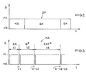
- Fig. 2 is a schematic diagram of one of the base station the data packet DP transmitted from the transponder at the output the modulator / demodulator unit MD with a head section KA, to which a data section DA with user data to be transmitted and an end portion EA connects.
- the head portion KA of Fig. 2 is shown in Fig. 3 in more detail.
- three symbols ZA, 0 * and EOT * are included.
- the symbols ZA, O * and EOT * are generated by successive field gaps or so-called "notches" of the carrier signal emitted by the base station BS, which are shown in FIG. 3 as short pulses.
- the first symbol ZA has a duration t1
- the second symbol 0 * has a duration t2
- the third symbol EOT * has a duration t3, the time periods t1 to t3 being determined by the time detection unit ZE of FIG.
- time recording unit ZE is implemented as a digital counter circuit DZS
- a respective counter value associated with the time periods t1 to t3 is stored in the memory SP of the control unit ST.
- time detection unit ZE is implemented as an RC circuit RCS, a voltage value obtained is correspondingly stored in the memory SP.
- the clock frequency f or the charging current I of the time recording unit ZE is determined by the control unit ST after the start of the transponder TR initialized with a minimum value, so that there is a minimum power consumption of the transponder TR results. This allows a start of the Transponders TR also in the far field of the base station BS.
- the increase can be single-stage or multi-level, for example proportional to the difference between the determined and deposited value.
- the clock frequency f or the charging current I can be Consequently, realize a large transmission rate range, while simultaneously by the low-power start of the transponder TR high Transmission ranges are realizable.
- the base station To transmit the payload data in the data section DA, the base station generates successive field gaps whose time interval corresponds to the characters to be transmitted.
- the transponder or its time recording unit ZE measures the distance of these field gaps with the time resolution set on the basis of the time t1 and compares the measured times with the times t2 and t3 of the symbols 0 * and EOT * .
- the symbol 0 * or its associated time duration t2 serves to encode or decode the binary characters "0" and "1", respectively, from which the user data to be transmitted in the data section DA are constructed.
- the symbol EOT * is used to identify the end of a data packet DP and is transmitted in the end section EA of the data packet DP, for which purpose arbitrary waveforms derived from t3 can be used.
- a binary character in the data section DA whose time duration is smaller than the time duration t2 associated with the symbol 0 * is interpreted as a "0" in the transponder TR.
- a character whose time duration is greater than t2 and less than the time period t3 associated with the symbol EOT * is interpreted as a "1". If the time interval between two successive field gaps is greater than t3, the transponder TR recognizes the end of a data packet.
- Data transmission from the transponder to the base station can also be done with the temporal resolution set on the basis of the time t1, for example according to the German patent application 102 04 347 described method.
- the decoding determining parameter is in the illustrated embodiment the temporal resolution of coding or decoding, however, it is alternatively possible depending on the character representation information further the coding and / or decoding mode set determining parameters, such as the type the coding between different coding variants to switch.
Landscapes
- Engineering & Computer Science (AREA)
- Computer Networks & Wireless Communication (AREA)
- Signal Processing (AREA)
- Quality & Reliability (AREA)
- Power Engineering (AREA)
- Mobile Radio Communication Systems (AREA)
- Near-Field Transmission Systems (AREA)
Abstract
Description
- Fig. 1
- ein schematisches Blockschaltbild eines RFID-Systems mit einer Basisstation und einem Transponder,
- Fig. 2
- ein schematisches Diagramm eines Datenpaketes mit einem Kopfabschnitt, einem Datenabschnitt und einem Endabschnitt und
- Fig. 3
- ein schematisches Diagramm des Kopfabschnitts von Fig. 2.
Claims (8)
- Verfahren zur drahtlosen Datenübertragung zwischen einer Basisstation (BS) und einem, insbesondere passiven, Transponder (TR), bei demdadurch gekennzeichnet, dasszu übertragende Datenpakete (DP) auf elektromagnetische Trägerwellen aufmoduliert werden unddie Datenpakete (DP) einen Kopfabschnitt (KA) mit mindestens einem Symbol (ZA, 0*, EOT*) und mindestens einen weiteren Abschnitt (DA) umfassen,im Transponder (TR) die Zeitdauer (t1) von wenigstens einem Symbol (ZA) im Kopfabschnitt (KA) ermittelt wird undin Abhängigkeit von der ermittelten Zeitdauer (t1) ein die Kodierungs- und/oder Dekodierungs-Betriebsart bestimmender Parameter (f, I) eingestellt wird.
- Verfahren nach Anspruch 1, dadurch gekennzeichnet, dass der Parameter (f, l) die zeitliche Auflösung der Kodierung und/oder der Dekodierung bestimmt.
- Verfahren nach einem der vorhergehenden Ansprüche, dadurch gekennzeichnet, dass der Parameter ein Ladestrom (I) einer RC-Schaltung (RCS) ist, die zur Ermittlung der Zeitdauern (t1, t2, t3) des oder der Symbole (ZA, 0*, EOT*) dient.
- Verfahren nach Anspruch 1 oder 2, dadurch gekennzeichnet, dass der Parameter eine Taktfrequenz (f) einer Zählerschaltung (DZS) ist, die zur Ermittlung der Zeitdauern (t1, t2, t3) des oder der Symbole (ZA, 0*, EOT*) dient.
- Verfahren nach einem der vorhergehenden Ansprüche, dadurch gekennzeichnet, dass der Parameter (f, l) in Abhängigkeit von der ermittelten Zeitdauer (t1) des ersten Symbols (ZA) im Kopfabschnitt (KA) eingestellt wird.
- Verfahren nach Anspruch 3 oder 5, dadurch gekennzeichnet, dass der Ladestrom (I) vor dem Empfang eines ersten Datenpakets (DP) einen vorgebbaren Minimalwert einnimmt, der bei Empfang des ersten Datenpakets (DP) erhöht wird, wenn ein zur ermittelten Zeitdauer (t1) des Symbols (ZA) gehöriger Spannungswert der RC-Schaltung (RCS) kleiner als oder gleich groß wie ein einstellbarer Grenzwert ist, und beibehalten wird, wenn der zu der Zeitdauer (t1) des Symbols (ZA) gehörige Spannungswert größer als der einstellbare Grenzwert ist.
- Verfahren nach Anspruch 4 oder 5, dadurch gekennzeichnet, dass die Taktfrequenz (f) vor dem Empfang eines ersten Datenpakets (DP) einen vorgebbaren Minimalwert einnimmt, der bei Empfang des ersten Datenpakets (DP) erhöht wird; wenn ein zur ermittelten Zeitdauer (t1) des Symbols (ZA) gehöriger Zählerwert der Zählerschaltung (DZS) kleiner als oder gleich groß wie ein einstellbarer Grenzwert ist, und beibehalten wird, wenn der zu der Zeitdauer (t1) des Symbols (ZA) gehörige Zählerwert größer als der einstellbare Grenzwert ist.
- Verfahren nach einem der vorhergehenden Ansprüche, dadurch gekennzeichnet, dass der mindestens eine weitere Abschnitt ein Datenabschnitt (DA) ist, dessen Daten mit Hilfe mindestens eines weiteren Symbols (0*, EOT*) des Kopfabschnitts (KA) kodiert und übertragen werden.
Applications Claiming Priority (2)
| Application Number | Priority Date | Filing Date | Title |
|---|---|---|---|
| DE10335009A DE10335009A1 (de) | 2003-07-23 | 2003-07-23 | Verfahren zur drahtlosen Datenübertragung zwischen einer Basisstation und einem Transponder |
| DE10335009 | 2003-07-23 |
Publications (2)
| Publication Number | Publication Date |
|---|---|
| EP1501250A2 true EP1501250A2 (de) | 2005-01-26 |
| EP1501250A3 EP1501250A3 (de) | 2009-04-15 |
Family
ID=33483096
Family Applications (1)
| Application Number | Title | Priority Date | Filing Date |
|---|---|---|---|
| EP04017298A Withdrawn EP1501250A3 (de) | 2003-07-23 | 2004-07-22 | Verfahren zur drahtlosen Datenübertragung zwischen einer Basisstation und einem Transponder |
Country Status (4)
| Country | Link |
|---|---|
| US (1) | US7376391B2 (de) |
| EP (1) | EP1501250A3 (de) |
| CN (1) | CN100365942C (de) |
| DE (1) | DE10335009A1 (de) |
Cited By (2)
| Publication number | Priority date | Publication date | Assignee | Title |
|---|---|---|---|---|
| EP1587023A1 (de) * | 2004-04-14 | 2005-10-19 | ATMEL Germany GmbH | Verfahren zur Datenkommunikation zwischen einer Basisstation und einem Transponder |
| CN101223537A (zh) * | 2005-07-12 | 2008-07-16 | 英特尔公司 | 能够嵌入接收机信号强度指示的射频识别标签 |
Families Citing this family (14)
| Publication number | Priority date | Publication date | Assignee | Title |
|---|---|---|---|---|
| DE10335003A1 (de) * | 2003-07-23 | 2005-02-10 | Atmel Germany Gmbh | Verfahren zur drahtlosen Datenübertragung zwischen einer Basisstation und einem Transponder |
| DE102004013885B4 (de) * | 2004-03-16 | 2012-08-30 | Atmel Automotive Gmbh | Verfahren sowie Modulationssteuereinrichtung zur drahtlosen Datenübertragung |
| DE102005009765B3 (de) * | 2005-03-03 | 2006-06-14 | Atmel Germany Gmbh | Selektionsverfahren für eine Datenkommunikation zwischen Basisstation und Transponder |
| US20070177694A1 (en) * | 2006-01-17 | 2007-08-02 | Symbol Technologies, Inc. | Method and apparatus for signal processing in RFID receivers |
| DE102006007262B3 (de) | 2006-02-10 | 2007-05-10 | Atmel Germany Gmbh | Verfahren zur drahtlosen Datenübertragung zwischen einer Basisstation und einem Transponder mittels induktiver Kopplung |
| DE102006057602B3 (de) * | 2006-11-27 | 2008-04-10 | Atmel Germany Gmbh | Verfahren zur drahtlosen Datenübertragung zwischen einer Basisstation und einem passiven Transponder sowie passiver Transponder |
| US9064196B1 (en) * | 2008-03-13 | 2015-06-23 | Impinj, Inc. | RFID tag dynamically adjusting clock frequency |
| US8154402B2 (en) * | 2009-03-12 | 2012-04-10 | Raytheon Company | Wireless temperature sensor network |
| CN102484580A (zh) * | 2009-05-28 | 2012-05-30 | Kovio股份有限公司 | 用于校验来自无线装置的代码的方法和系统 |
| WO2013025311A1 (en) * | 2011-08-12 | 2013-02-21 | Rambus Inc. | Temporal redundancy |
| US10566843B2 (en) * | 2014-07-15 | 2020-02-18 | Qorvo Us, Inc. | Wireless charging circuit |
| EP3462276A4 (de) * | 2017-08-04 | 2019-08-21 | Shenzhen Goodix Technology Co., Ltd. | Timing-verfahren, taktvorrichtung und endgerätevorrichtung |
| CN110753255B (zh) * | 2018-07-24 | 2022-07-29 | 扬智科技股份有限公司 | 传输串流接收装置及其时钟频率设定方法 |
| CN113014522B (zh) * | 2020-12-30 | 2022-10-25 | 南斗六星系统集成有限公司 | 一种无线数据的解码方法及系统 |
Family Cites Families (14)
| Publication number | Priority date | Publication date | Assignee | Title |
|---|---|---|---|---|
| JPH0983583A (ja) * | 1995-09-12 | 1997-03-28 | Sharp Corp | Fsk通信装置 |
| US5838873A (en) * | 1996-05-31 | 1998-11-17 | Thomson Consumer Electronics, Inc. | Packetized data formats for digital data storage media |
| US5754651A (en) * | 1996-05-31 | 1998-05-19 | Thomson Consumer Electronics, Inc. | Processing and storage of digital data and program specific information |
| DE19646747C1 (de) * | 1996-11-01 | 1998-08-13 | Nanotron Ges Fuer Mikrotechnik | Verfahren zur drahtlosen Übertragung einer einem Signal aufgeprägten Nachricht |
| DE19744781C2 (de) * | 1997-10-10 | 2000-03-02 | Anatoli Stobbe | Verfahren zur Datenübertragung zwischen einem Schreib-Lesegerät und einem Transponder sowie Vorrichtung zur Durchführung des Verfahrens |
| EP1026627A1 (de) * | 1999-01-29 | 2000-08-09 | Siemens Aktiengesellschaft | Kontaktloses Datenübertragungssystem und Verfahren zur kontaktlosen Datenübertragung |
| JP4884631B2 (ja) | 2000-01-20 | 2012-02-29 | ノーテル・ネットワークス・リミテッド | 可変速度パケット・データ・アプリケーションでのソフト組合せを備えたハイブリッドarq方式 |
| US6650705B1 (en) * | 2000-05-26 | 2003-11-18 | Mitsubishi Electric Research Laboratories Inc. | Method for encoding and transcoding multiple video objects with variable temporal resolution |
| US7099266B2 (en) * | 2001-03-26 | 2006-08-29 | Victor Company Of Japan, Limited | Orthogonal frequency division multiplexed signal transmitting apparatus, orthogonal frequency division multiplexed signal receiving apparatus, and orthogonal frequency division multiplexed signal transmitting/receiving system |
| DE10138217A1 (de) * | 2001-08-03 | 2003-03-20 | Atmel Germany Gmbh | Verfahren zur Übertragung von Daten |
| DE10138218B4 (de) * | 2001-08-03 | 2004-01-22 | Atmel Germany Gmbh | Verfahren zur Übertragung von Daten |
| DE10204347A1 (de) | 2002-02-01 | 2003-08-14 | Atmel Germany Gmbh | Verfahren zur Übertragung von Daten |
| EP1394719B1 (de) * | 2002-09-02 | 2007-05-30 | EM Microelectronic-Marin SA | Anpassung der Sende- und Empfangseigenschaften eines RFID Lesers in Abhängigkeit vom elektromagnetischen Umgebungsrauschen |
| DE10335003A1 (de) * | 2003-07-23 | 2005-02-10 | Atmel Germany Gmbh | Verfahren zur drahtlosen Datenübertragung zwischen einer Basisstation und einem Transponder |
-
2003
- 2003-07-23 DE DE10335009A patent/DE10335009A1/de not_active Withdrawn
-
2004
- 2004-07-21 US US10/896,670 patent/US7376391B2/en not_active Expired - Fee Related
- 2004-07-22 EP EP04017298A patent/EP1501250A3/de not_active Withdrawn
- 2004-07-22 CN CNB2004100544685A patent/CN100365942C/zh not_active Expired - Fee Related
Cited By (4)
| Publication number | Priority date | Publication date | Assignee | Title |
|---|---|---|---|---|
| EP1587023A1 (de) * | 2004-04-14 | 2005-10-19 | ATMEL Germany GmbH | Verfahren zur Datenkommunikation zwischen einer Basisstation und einem Transponder |
| US8254841B2 (en) | 2004-04-14 | 2012-08-28 | Atmel Corporation | Method and apparatus for data communication between a base station and a transponder |
| CN101223537A (zh) * | 2005-07-12 | 2008-07-16 | 英特尔公司 | 能够嵌入接收机信号强度指示的射频识别标签 |
| CN101223537B (zh) * | 2005-07-12 | 2014-12-10 | 英特尔公司 | 能够嵌入接收机信号强度指示的射频识别标签 |
Also Published As
| Publication number | Publication date |
|---|---|
| CN1578177A (zh) | 2005-02-09 |
| DE10335009A1 (de) | 2005-02-10 |
| EP1501250A3 (de) | 2009-04-15 |
| CN100365942C (zh) | 2008-01-30 |
| US20050018639A1 (en) | 2005-01-27 |
| US7376391B2 (en) | 2008-05-20 |
Similar Documents
| Publication | Publication Date | Title |
|---|---|---|
| EP1508870B1 (de) | Verfahren zur drahtlosen Datenübertragung zwischen einer Basisstation und einem Transponder | |
| EP1501250A2 (de) | Verfahren zur drahtlosen Datenübertragung zwischen einer Basisstation und einem Transponder | |
| DE3780508T2 (de) | Hf-system zur automatischen fernablesung von instrumenten. | |
| WO2003015333A2 (de) | Verfahren zur übertragung von daten | |
| EP1738297B1 (de) | Verfahren zum auswählen eines oder mehrerer transponder | |
| EP1026627A1 (de) | Kontaktloses Datenübertragungssystem und Verfahren zur kontaktlosen Datenübertragung | |
| EP1587023B1 (de) | Verfahren zur Datenkommunikation zwischen einer Basisstation und einem Transponder | |
| DE102004013885B4 (de) | Verfahren sowie Modulationssteuereinrichtung zur drahtlosen Datenübertragung | |
| EP1675033A1 (de) | Verfahren zur drahtlosen Datenübertragung | |
| DE102004013837B4 (de) | Verfahren zur drahtlosen Datenübertragung | |
| DE102004006446B4 (de) | Verfahren und Schaltungsanordnung zur drahtlosen Datenübertragung | |
| WO2003065286A1 (de) | Verfahren zur übertragung von daten zwischen einer basisstation und einem transponder | |
| DE102005009765B3 (de) | Selektionsverfahren für eine Datenkommunikation zwischen Basisstation und Transponder | |
| WO2008064824A1 (de) | Verfahren zur drahtlosen datenübertragung zwischen einer basisstation und einem passiven transponder sowie passiver transponder | |
| DE102014117791B4 (de) | Passiver Leser zur Identifikation mit Hilfe elektromagnetischer Wellen (RFID), passives RFID-Etikett und Übertragungs- und Empfangsverfahren mittels erweiterter Pulsintervallcodierung (PIE) | |
| EP1587022B1 (de) | Verfahren zur drahtlosen Datenübertragung | |
| AT401127B (de) | Kontaktloses datenübertragungssystem | |
| DE4445285A1 (de) | Codeantwortsystem, welches eine Änderung des Reflexionsgrades einer gesendeten elektromagnetischen Welle verwendet | |
| EP1818853A2 (de) | Verfahren zur drahtlosen Datenübertragung zwischen einer Basisstation und einem Transponder mittels induktiver Kopplung | |
| DE102004019311B3 (de) | Verfahren sowie Vorrichtung zur drahtlosen Datenübertragung | |
| EP1735735A1 (de) | Verfahren und vorrichtung zum erkennen von funktionszuständen in rfid- oder remote-sensor-systemen | |
| DE19948765A1 (de) | Verfahren zur Signalübertragung in einem Bussystem zwischen einer Zentraleinheit und einer Anzahl von Modulen durch Veränderung der Stromaufnahme eines Moduls aufgelagert auf eine Versorgungsgleichspannung | |
| DE102004018542A1 (de) | Verfahren zur Datenkommunikation zwischen einer Basisstation und einem Transponder | |
| DE102008053097A1 (de) | Transpondereinheit | |
| DE102004018556A1 (de) | Verfahren zur Datenkommunikation zwischen einer Basisstation und einem Transponder |
Legal Events
| Date | Code | Title | Description |
|---|---|---|---|
| PUAI | Public reference made under article 153(3) epc to a published international application that has entered the european phase |
Free format text: ORIGINAL CODE: 0009012 |
|
| AK | Designated contracting states |
Kind code of ref document: A2 Designated state(s): AT BE BG CH CY CZ DE DK EE ES FI FR GB GR HU IE IT LI LU MC NL PL PT RO SE SI SK TR |
|
| AX | Request for extension of the european patent |
Extension state: AL HR LT LV MK |
|
| PUAL | Search report despatched |
Free format text: ORIGINAL CODE: 0009013 |
|
| STAA | Information on the status of an ep patent application or granted ep patent |
Free format text: STATUS: THE APPLICATION HAS BEEN WITHDRAWN |
|
| AK | Designated contracting states |
Kind code of ref document: A3 Designated state(s): AT BE BG CH CY CZ DE DK EE ES FI FR GB GR HU IE IT LI LU MC NL PL PT RO SE SI SK TR |
|
| AX | Request for extension of the european patent |
Extension state: AL HR LT LV MK |
|
| RIC1 | Information provided on ipc code assigned before grant |
Ipc: H04L 25/02 20060101ALI20090309BHEP Ipc: H04B 1/59 20060101ALI20090309BHEP Ipc: H04L 1/00 20060101AFI20090309BHEP |
|
| 18W | Application withdrawn |
Effective date: 20090403 |