EP1501207A1 - Method for regulating the transmit power in a radio system - Google Patents
Method for regulating the transmit power in a radio system Download PDFInfo
- Publication number
- EP1501207A1 EP1501207A1 EP04025574A EP04025574A EP1501207A1 EP 1501207 A1 EP1501207 A1 EP 1501207A1 EP 04025574 A EP04025574 A EP 04025574A EP 04025574 A EP04025574 A EP 04025574A EP 1501207 A1 EP1501207 A1 EP 1501207A1
- Authority
- EP
- European Patent Office
- Prior art keywords
- transmitter
- power control
- transmission power
- transmission
- power
- Prior art date
- Legal status (The legal status is an assumption and is not a legal conclusion. Google has not performed a legal analysis and makes no representation as to the accuracy of the status listed.)
- Granted
Links
Images


Classifications
-
- H—ELECTRICITY
- H04—ELECTRIC COMMUNICATION TECHNIQUE
- H04W—WIRELESS COMMUNICATION NETWORKS
- H04W52/00—Power management, e.g. TPC [Transmission Power Control], power saving or power classes
- H04W52/04—TPC
- H04W52/18—TPC being performed according to specific parameters
- H04W52/22—TPC being performed according to specific parameters taking into account previous information or commands
- H04W52/228—TPC being performed according to specific parameters taking into account previous information or commands using past power values or information
-
- H—ELECTRICITY
- H04—ELECTRIC COMMUNICATION TECHNIQUE
- H04W—WIRELESS COMMUNICATION NETWORKS
- H04W52/00—Power management, e.g. TPC [Transmission Power Control], power saving or power classes
- H04W52/04—TPC
- H04W52/18—TPC being performed according to specific parameters
- H04W52/22—TPC being performed according to specific parameters taking into account previous information or commands
- H04W52/221—TPC being performed according to specific parameters taking into account previous information or commands using past power control commands
-
- H—ELECTRICITY
- H04—ELECTRIC COMMUNICATION TECHNIQUE
- H04W—WIRELESS COMMUNICATION NETWORKS
- H04W52/00—Power management, e.g. TPC [Transmission Power Control], power saving or power classes
- H04W52/04—TPC
- H04W52/30—TPC using constraints in the total amount of available transmission power
- H04W52/36—TPC using constraints in the total amount of available transmission power with a discrete range or set of values, e.g. step size, ramping or offsets
- H04W52/362—Aspects of the step size
-
- H—ELECTRICITY
- H04—ELECTRIC COMMUNICATION TECHNIQUE
- H04W—WIRELESS COMMUNICATION NETWORKS
- H04W52/00—Power management, e.g. TPC [Transmission Power Control], power saving or power classes
- H04W52/04—TPC
- H04W52/30—TPC using constraints in the total amount of available transmission power
- H04W52/36—TPC using constraints in the total amount of available transmission power with a discrete range or set of values, e.g. step size, ramping or offsets
- H04W52/367—Power values between minimum and maximum limits, e.g. dynamic range
-
- H—ELECTRICITY
- H04—ELECTRIC COMMUNICATION TECHNIQUE
- H04W—WIRELESS COMMUNICATION NETWORKS
- H04W52/00—Power management, e.g. TPC [Transmission Power Control], power saving or power classes
- H04W52/04—TPC
- H04W52/38—TPC being performed in particular situations
- H04W52/44—TPC being performed in particular situations in connection with interruption of transmission
Definitions
- the present invention relates to a method of control the transmission power in a radio system, in particular in one Mobile radio system.
- a transmitter transmits for example, a mobile station, a particular transmission signal, which is also referred to as a pilot signal to the Receiver, for example a base station.
- the pilot signal includes one or more pilot bits, which of the Base station are evaluated, depending on which the signal transmission ratio received by the respective transmission channel (Signal to Interference Ratio, SIR) to determine which is compared with a setpoint.
- SIR Signal to Interference Ratio
- FIG. 3 the Communication between a mobile station MS and a Base station BS of a mobile radio system, for example a UMTS mobile radio system, shown.
- the mobile station MS transmits over the directed from the mobile station to the base station Transmission channel, which acts as an "uplink" transmission channel is referred to, the previously described pilot signal, which is evaluated by the base station BS.
- the base station BS then generates power control commands via the directed from the base station to the mobile station Transmission channel acting as a "downlink" transmission channel is sent to the mobile station MS.
- Power control commands merely provide information which instruct the mobile station (MS) to increase its transmit power by one amount to increase or decrease or even to leave unchanged.
- the Power control command thus comprise only one bit, which instructs the mobile station MS, depending on its value, its transmission power to increase by the aforementioned value or to decrease.
- the communication between the mobile station MS and the Base station BS is in the form of a frame and Time slot structure, in particular in each time slot a new pilot signal is sent from the mobile station MS. Accordingly, the base station BS in each Timeslot a new power control command to the Mobile station MS sent on the during the previous time slot transmitted pilot signal is based.
- Time slots are present in which no Information transfer takes place.
- transmission gap a transmission gap which among other things for neighboring channel observations, in preparation can be used by handover operations or the like.
- the base station BS Occurs in the uplink and / or downlink channel such Transmission gap, the base station BS is missing to the Generation of power control commands required Pilot signal of the mobile station MS or the mobile station MS of the corresponding power control command of the base station BS.
- a transmission gap in the uplink and / or Downlink transmission channel is thus used to control the Transmission power of the mobile station MS serving closed Circuit disrupted, so during such a Transmission gap no power control commands sent can be.
- the estimated value ⁇ i which describes the expected transmission power change after a transmission gap, can be determined using the following recursive equations, where TPC i denotes the power control command received in time slot No.
- ⁇ i-1 ⁇ i
- the estimated value ⁇ i is to be recalculated by the mobile station MS continuously in all time slots in which both an uplink pilot signal and a downlink power control command are transmitted.
- the estimated value ⁇ i is also calculated in the first time slot of an uplink transmission gap if a downlink power control command has been transmitted in the corresponding time slot.
- the value ⁇ i-1 is set to 0 whenever the control channel of the mobile station Ms assigned to the uplink channel is initiated or activated.
- ⁇ i-1 is reset to zero at the end of the first time slot after each uplink transmission gap and at the end of the first time slot after each downlink transmission gap.
- the estimate for ⁇ i is set to 0 at the end of the first time slot after each uplink transmission gap.
- K denotes a parameter which has the value "0". If scaling should be performed, while the parameter k has the value "1", if none Scaling applied and the transmit power in the usual way and way to be determined.
- the scaling to be performed by the mobile station MS can be chosen such that in the vicinity of the minimum Transmission power Pmin power control commands, which a further reduction of the transmission power of the mobile station Result, basically with a certain factor, for example, with 1/4, multiplied and thus attenuated while power control commands, which are a Increase the transmission power without scaling be applied.
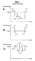
- FIG. 5A A corresponding course of the transmission power is shown in FIG. 5A shown.
- the mobile station MS is already close to the minimum Transmission power limit Pmin.
- receives the Mobile station a power control command, which the Reduced transmission power, reducing the minimum Transmit power limit Pmin would be exceeded.
- the Mobile station MS applies the aforementioned scaling and multiplies each subsequent power control command, which results in a reduction of the transmission power, with the factor 1/4, so these power control commands be weakened.
- the mobile station MS receives a Power control command, which increases the transmission power entails.
- those power control commands which to a Transmission power below the minimum transmission power limit Pmin would put in the ⁇ -formulas by putting the Parameter k to "0" does not affect the tendency of Power control commands come in while Power control commands, which jump the Transmission power up or above the minimum Transmit power limit Pmin addition, in the Estimate ⁇ .
- Power control commands which jump the Transmission power up or above the minimum Transmit power limit Pmin addition, in the Estimate ⁇ .
- a similar problem can also be at the maximum Transmission power limit Pmax occur, with the scaling For example, may be selected such that at a Power control command, which is to exceed the maximum transmission power limit Pmax would cause this Power control command is reduced such that only with the amount of the maximum transmission power Pmax is sent. When a power control command occurs, which falls below the maximum transmission line limit would result in no scaling.
- FIG. 5C A corresponding transmission power curve is shown in FIG. 5C shown.
- enter Power control command on which the transmission power of Mobile station MS decreases, no scaling is applied (k 1), and this power control command becomes full implemented so that the maximum transmission power limit significantly is fallen short of.
- the present invention is therefore based on the object an improved method for controlling the transmission power in a radio system, in particular a mobile radio system, to propose, thus avoiding the aforementioned problems and also in the range of transmission power limits an exact and realistic control of the transmission power is possible.
- the present invention is particularly suitable for UMTS mobile radio systems, where after occurrence of a transmission gap an estimated value for the transmission power control is determined.
- the present invention is on any radio systems applicable, in which in the field of Transmit power limits Scaling method for use come.
- FIG. 1 shows a transmission power curve according to a scaling method according to the invention, wherein the transmission power curve shown in FIG. 1 corresponds to the transmission power curve shown in FIG. 5A.
- the mobile station MS whose transmission power is to be regulated is already close to the minimum transmission power limit Pmin.
- the mobile station MS receives a power control command, which would fall below the minimum transmission power limit Pmin.
- FIG. 2 which corresponds to the transmission profile shown in FIG. 5C.
Abstract
Description
Die vorliegende Erfindung betrifft ein Verfahren zur Regelung der Sendeleistung in einem Funksystem, insbesondere in einem Mobilfunksystem.The present invention relates to a method of control the transmission power in a radio system, in particular in one Mobile radio system.
In Mobilfunksystemen, beispielsweise gemäß dem UMTS-Mobilfunkstandard ("Universal Mobile Telecommunication System"), ist eine kontinuierliche Regelung der Sendeleistung der Basisstationen und der Mobilstationen vorgesehen. Dabei erfolgt die Regelung der Sendeleistung insbesondere in Form eines geschlossenen Regelkreises ("Closed Loop Power Control"). Zu diesem Zweck überträgt ein Sender, beispielsweise eine Mobilstation, ein bestimmtes Sendesignal, welches auch als Pilotsignal bezeichnet wird, an den Empfänger, beispielsweise eine Basisstation. Das Pilotsignal umfasst dabei ein oder mehrere Pilotbits, welche von der Basisstation ausgewertet werden, um davon abhängig das auf dem jeweiligen Übertragungskanal empfangene Signal-Interferenz-Verhältnis ("Signal to Interference Ratio", SIR) zu bestimmen, welches mit einem Sollwert verglichen wird. Die Basisstation sendet daraufhin einen Leistungsregelungsbefehl an die Mobilstation, welcher abhängig von dem Vergleichsergebnis eine Erhöhung oder Erniedrigung der Sendeleistung der Mobilstation zum Ziel hat.In mobile radio systems, for example according to the UMTS mobile radio standard (Universal Mobile Telecommunication System "), is a continuous control of the transmission power the base stations and the mobile stations provided. there the control of the transmission power takes place in particular in the form a closed loop ("closed loop power Control "). For this purpose, a transmitter transmits for example, a mobile station, a particular transmission signal, which is also referred to as a pilot signal to the Receiver, for example a base station. The pilot signal includes one or more pilot bits, which of the Base station are evaluated, depending on which the signal transmission ratio received by the respective transmission channel (Signal to Interference Ratio, SIR) to determine which is compared with a setpoint. The Base station then sends a power control command to the mobile station, which depends on the Comparison result an increase or decrease in the Transmission power of the mobile station has to the destination.
Zur Verdeutlichung dieses Vorgangs ist in Figur 3 die Kommunikation zwischen einer Mobilstation MS und einer Basisstation BS eines Mobilfunksystems, beispielsweise eines UMTS-Mobilfunksystems, dargestellt. Nachfolgend wird davon ausgegangen, dass die Sendeleistung der Mobilstation MS geregelt werden soll. Die Mobilstation MS überträgt über den von der Mobilstation zu der Basisstation gerichteten Übertragungskanal, welcher als "Uplink"-Übertragungskanal bezeichnet wird, das zuvor beschriebene Pilotsignal, welches von der Basisstation BS ausgewertet wird. Die Basisstation BS erzeugt daraufhin Leistungsregelungsbefehle, welche über den von der Basisstation zu der Mobilstation gerichteten Übertragungskanal, der als "Downlink"-Übertragungskanal bezeichnet wird, an die Mobilstation MS gesendet werden. In der Regel handelt es sich bei diesen Leistungsregelungsbefehlen lediglich um Informationen, welche die Mobilstation (MS) anweisen, ihre Sendeleistung um einen vorgegebenen Betrag zu erhöhen bzw. zu erniedrigen oder auch unverändert zu lassen. Im Prinzip kann der Leistungsregelungsbefehl somit lediglich ein Bit umfassen, welches abhängig von seinem Wert die Mobilstation MS anweist, seine Sendeleistung um den zuvor erwähnten Wert zu erhöhen bzw. zu erniedrigen.To illustrate this process is in Figure 3 the Communication between a mobile station MS and a Base station BS of a mobile radio system, for example a UMTS mobile radio system, shown. Below is from it assumed that the transmission power of the mobile station MS should be regulated. The mobile station MS transmits over the directed from the mobile station to the base station Transmission channel, which acts as an "uplink" transmission channel is referred to, the previously described pilot signal, which is evaluated by the base station BS. The base station BS then generates power control commands via the directed from the base station to the mobile station Transmission channel acting as a "downlink" transmission channel is sent to the mobile station MS. In usually these are Power control commands merely provide information which instruct the mobile station (MS) to increase its transmit power by one amount to increase or decrease or even to leave unchanged. In principle, the Power control command thus comprise only one bit, which instructs the mobile station MS, depending on its value, its transmission power to increase by the aforementioned value or to decrease.
Die Kommunikation zwischen der Mobilstation MS und der Basisstation BS erfolgt in Form einer Rahmen- und Zeitschlitzstruktur, wobei insbesondere in jedem Zeitschlitz ein neues Pilotsignal von der Mobilstation MS gesendet wird. Entsprechend wird von der Basisstation BS in jedem Zeitschlitz ein neuer Leistungsregelungsbefehl an die Mobilstation MS gesendet, welcher auf dem während des vorhergehenden Zeitschlitzes gesendeten Pilotsignal beruht.The communication between the mobile station MS and the Base station BS is in the form of a frame and Time slot structure, in particular in each time slot a new pilot signal is sent from the mobile station MS. Accordingly, the base station BS in each Timeslot a new power control command to the Mobile station MS sent on the during the previous time slot transmitted pilot signal is based.
Für den UMTS-Mobilfunkstandard ist ein sogenannter "Compressed Mode" definiert, welcher vorsieht, dass die über den Uplink- und/oder Downlink-Übertragungskanal zu übertragenden Informationen in komprimierter Form übertragen werden. Dies hat zur Folge, dass in einem im "Compressed Mode" gesendeten komprimierten Rahmen ein oder mehrere Zeitschlitze vorhanden sind, in denen keine Informationsübertragung stattfindet. Diese Zeitschlitze bilden eine Übertragungslücke ("Transmission Gap"), welche unter anderem für Nachbarkanalbeobachtungen, zur Vorbereitung von Handover-Vorgängen oder dergleichen genutzt werden kann. For the UMTS mobile radio standard is a so-called Defined "Compressed Mode", which provides that over the uplink and / or downlink transmission channel transmit transmitted information in compressed form become. This has the consequence that in a "Compressed Mode "compressed one or more compressed frames Time slots are present in which no Information transfer takes place. These timeslots form a transmission gap ("transmission gap") which among other things for neighboring channel observations, in preparation can be used by handover operations or the like.
Tritt im Uplink- und/oder Downlink-Kanal eine derartige Übertragungslücke auf, fehlt der Basisstation BS das zur Erzeugung der Leistungsregelungsbefehle erforderliche Pilotsignal der Mobilstation MS oder der Mobilstation MS der entsprechende Leistungsregelungsbefehl der Basisstation BS. Durch eine derartige Übertragungslücke im Uplink- und/oder Downlink-Übertragungskanal wird somit der zur Regelung der Sendeleistung der Mobilstation MS dienende geschlossene Regelkreis gestört, so dass während einer derartigen Übertragungslücke keine Leistungsregelungsbefehle gesendet werden können.Occurs in the uplink and / or downlink channel such Transmission gap, the base station BS is missing to the Generation of power control commands required Pilot signal of the mobile station MS or the mobile station MS of the corresponding power control command of the base station BS. Through such a transmission gap in the uplink and / or Downlink transmission channel is thus used to control the Transmission power of the mobile station MS serving closed Circuit disrupted, so during such a Transmission gap no power control commands sent can be.
Die obige Beschreibung ist selbstverständlich im Prinzip auch auf eine Regelung der Sendeleistung der Basisstation BS anwendbar, wobei jedoch die vorliegende Erfindung nachfolgend - ohne Einschränkung der Allgemeinheit - anhand einer Regelung der Sendeleistung der Mobilstation MS beschrieben wird.The above description is of course also in principle to a regulation of the transmission power of the base station BS applicable, but the present invention below - without restriction of the general public - by means of a Regulation of the transmission power of the mobile station MS described becomes.
Um das zuvor mit dem Auftreten einer Übertragungslücke
verbundenen Problem bei der Sendeleistungsregelung zu lösen,
wurde bezüglich des UMTS-Mobilfunkstandards vorgeschlagen,
anhand der in der Vergangenheit erzeugten
Leistungsregelungsbefehle einen Schätzwert für den in Zukunft
zu erwartenden Leistungsregelungsbefehl zu erzeugen, so dass
dieser Schätzwert nach dem Auftreten einer Übertragungslücke
der Regelung der Sendeleistung zu Grunde gelegt werden kann.
Dabei kann der Schätzwert δi, welcher die zu erwartende
Sendeleistungsänderung nach einer Übertragungslücke
beschreibt, insbesondere mit Hilfe der folgenden rekursiven
Gleichungen ermittelt werden, wobei TPCi den im Zeitschlitz
Nr. i empfangenen Leistungsregelungsbefehl und ΔTPC die zur
Einstellung der Sendeleistung zur Verfügung stehende
Schrittweite bezeichnet. δi-1 bezeichnet den für den
vorhergehenden Zeitschlitz i-1 ermittelten Schätzwert:
Bei der Regelung der Sendeleistung einer Mobilstation (Vergleiche Figur 3) soll der Schätzwert δi von der Mobilstation MS kontinuierlich in allen Zeitschlitzen neu berechnet werden, in denen sowohl ein Uplink-Pilotsignal als auch ein Downlink-Leistungsregelungsbefehl übertragen wird. Zudem wird der Schätzwert δi auch in dem ersten Zeitschlitz einer Uplink-Übertragungslücke berechnet, falls in dem entsprechenden Zeitschlitz ein Downlink-Leistungsregelungsbefehl übertragen worden ist. Der Wert δi-1 wird immer dann auf 0 gesetzt, wenn der dem Uplink-Kanal zugeordnete Steuerkanal der Mobilstation Ms initiiert oder aktiviert wird. Des Weiteren wird δi-1 am Ende des ersten Zeitschlitzes nach jeder Uplink-Übertragungslücke und am Ende des ersten Zeitschlitzes nach jeder Downlink-Übertragungslücke auf Null zurückgesetzt. Der Schätzwert für δi wird jeweils am Ende des ersten Zeitschlitzes nach jeder Uplink-Übertragungslücke auf 0 gesetzt.In the regulation of the transmission power of a mobile station (compare FIG. 3), the estimated value δ i is to be recalculated by the mobile station MS continuously in all time slots in which both an uplink pilot signal and a downlink power control command are transmitted. In addition, the estimated value δ i is also calculated in the first time slot of an uplink transmission gap if a downlink power control command has been transmitted in the corresponding time slot. The value δ i-1 is set to 0 whenever the control channel of the mobile station Ms assigned to the uplink channel is initiated or activated. Furthermore, δ i-1 is reset to zero at the end of the first time slot after each uplink transmission gap and at the end of the first time slot after each downlink transmission gap. The estimate for δ i is set to 0 at the end of the first time slot after each uplink transmission gap.
Ein mit den obigen Formeln bzw. der zuvor beschriebenen
Vorgehensweise verbundenes Problem tritt jedoch auf, wenn
sich die von der Mobilstation MS emittierte Sendeleistung
nahe einer vorgegebenen maximalen Sendeleistung Pmax bzw.
minimalen Sendeleistung Pmin befindet. Es wurde für UMTS-Mobilfunksysteme
vorgeschlagen, in der Nähe derartiger
Sendeleistungsgrenzwerte eine Skalierung durchzuführen, um
ein deutliches Unterschreiten der vorgegebenen minimalen
Sendeleistung Pmin bzw. ein deutliches Überschreiten der
vorgegebenen maximalen Sendeleistung Pmax zu verhindern.
Durch diese Skalierung wird die obige Formel (1) durch
folgende Formel ersetzt:
Dabei bezeichnet k einen Parameter, welcher den Wert "0" annimmt, wenn eine Skalierung durchgeführt werden soll, während der Parameter k den Wert "1" besitzt, wenn keine Skalierung angewendet und die Sendeleistung auf übliche Art und Weise ermittelt werden soll.K denotes a parameter which has the value "0". assumes that scaling should be performed, while the parameter k has the value "1", if none Scaling applied and the transmit power in the usual way and way to be determined.
Der Parameter k wird herkömmlicherweise immer dann auf k=0 gesetzt, wenn die von der Mobilstation MS emittierte Sendeleistung auf Grund vorhergegangener Leistungsregelungsbefehle die vorgegebene maximale Sendeleistung Pmax überschreiten bzw. die vorgegebene minimale Sendeleistung Pmin unterschreiten würde. In anderen Fällen wird k=1 verwendet.The parameter k is conventionally always set to k = 0 set when emitted by the mobile station MS Transmission power based on previous Power control commands the predetermined maximum Transmitting power Pmax exceed or the default minimum transmission power Pmin would fall below. In other Cases k = 1 is used.
Die von der Mobilstation MS durchzuführende Skalierung kann derart gewählt sein, dass in der Nähe der minimalen Sendeleistung Pmin Leistungsregelungsbefehle, welche eine weitere Verringerung der Sendeleistung der Mobilstation zur Folge haben, grundsätzlich mit einem bestimmten Faktor, beispielsweise mit 1/4, multipliziert und somit abgeschwächt werden, während Leistungsregelungsbefehle, welche eine Erhöhung der Sendeleistung zur Folge haben, ohne Skalierung angewendet werden.The scaling to be performed by the mobile station MS can be chosen such that in the vicinity of the minimum Transmission power Pmin power control commands, which a further reduction of the transmission power of the mobile station Result, basically with a certain factor, for example, with 1/4, multiplied and thus attenuated while power control commands, which are a Increase the transmission power without scaling be applied.
Ein entsprechender Verlauf der Sendeleistung ist in Figur 5A
dargestellt. Wie aus Figur 5A ersichtlich ist, befindet sich
die Mobilstation MS bereits nahe der minimalen
Sendeleistungsgrenze Pmin. Anschließend erhält die
Mobilstation einen Leistungsregelungsbefehl, welcher die
Sendeleistung verringert, wodurch die minimale
Sendeleistungsgrenze Pmin unterschritten werden würde. Die
Mobilstation MS wendet die zuvor erwähnte Skalierung an und
multipliziert jeden nachfolgenden Leistungsregelungsbefehl,
welcher eine Verringerung der Sendeleistung zur Folge hat,
mit dem Faktor 1/4, so dass diese Leistungsregelungsbefehle
abgeschwächt werden. Da für diese Leistungsregelungsbefehle
die Skalierung angewendet wird, besitzt der Parameter k den
Wert k=0. Am Ende des in Figur 5A gezeigten
Sendeleistungsverlaufs empfängt die Mobilstation MS einen
Leistungsregelungsbefehl, der eine Erhöhung der Sendeleistung
zur Folge hat. Dieser Leistungsregelungsbefehl wird ohne
Skalierung umgesetzt, so dass für diesen
Leistungsregelungsbefehl der Parameter k=1 beträgt.
Betrachtet man den zuvor erläuterten Sendeleistungsverlauf
hinsichtlich der zuvor beschriebenen δ-Formel, so würden
diejenigen Leistungsregelungsbefehle, welche zu einer
Sendeleistung unterhalb der minimalen Sendeleistungsgrenze
Pmin führen würden, in der δ-Formeln durch setzen des
Parameter k zu "0" nicht in die Tendenz der
Leistungsregelungsbefehle eingehen, während
Leistungsregelungsbefehle, welche einen Sprung der
Sendeleistung nach oben bzw. über die minimale
Sendeleistungsgrenze Pmin hinaus zur Folge haben, in den
Schätzwert δ eingehen. Würde sich der in Figur 5A gezeigte
Verlauf der Sendeleistung genau in der Art mehrfach
hintereinander wiederholen, so würde als Tendenz der
Sendeleistungsbefehle in der δ-Formel eine deutliche Erhöhung
der Sendeleistung berücksichtigt werden, was jedoch nicht der
Realität entspricht.A corresponding course of the transmission power is shown in FIG. 5A
shown. As can be seen from FIG. 5A, is located
the mobile station MS is already close to the minimum
Transmission power limit Pmin. Then receives the
Mobile station, a power control command, which the
Reduced transmission power, reducing the minimum
Transmit power limit Pmin would be exceeded. The
Mobile station MS applies the aforementioned scaling and
multiplies each subsequent power control command,
which results in a reduction of the transmission power,
with the
Bei Anwendung des zuvor beschriebenen Skalierungsverfahrens steht es der Mobilstation MS frei, ob es ein Unterschreiten der minimalen Sendeleistungsgrenze Pmin zulässt oder nicht. Sollte die Mobilstation MS ein Unterschreiten der minimalen Sendeleistungsgrenze Pmin nicht unterstützen, kann sich bei Anwendung des herkömmlichen Skalierungsverfahrens ein Sendeleistungsverlauf ergeben, wie er in Figur 5B gezeigt ist. Bei den in Figur 5B gezeigten Beispiel wird grundsätzlich bei Erreichen der minimalen Sendeleistungsgrenze Pmin die Skalierung derartig aktiviert, dass mit dem Wert der minimalen Sendeleistungsgrenze Pmin gesendet wird. Bei Erreichen der minimalen Sendeleistungsgrenze Pmin wird wiederum der Parameter auf k=0 gesetzt. Ansonsten gilt wiederum das bereits anhand Figur 5A erläuterte Prinzip. When using the previously described scaling method it is the mobile station MS free, if it falls below the minimum transmission power limit Pmin allows or not. Should the mobile station MS fall below the minimum Transmission power limit Pmin does not support, can at Application of the conventional scaling method Transmission power curve result, as shown in Figure 5B is. In the example shown in FIG. 5B basically when reaching the minimum Transmit power limit Pmin activates the scaling in this way, that with the value of the minimum transmission power limit Pmin is sent. Upon reaching the minimum Transmission power limit Pmin is again the parameter on k = 0 set. Otherwise, the same applies again with reference to FIG 5A explained principle.
Ein ähnliches Problem kann auch an der maximalen Sendeleistungsgrenze Pmax auftreten, wobei die Skalierung beispielsweise derart gewählt sein kann, dass bei einem Leistungsregelungsbefehl, welcher zum Überschreiten der maximalen Sendeleistungsgrenze Pmax führen würde, dieser Leistungsregelungsbefehl derart reduziert wird, dass lediglich mit dem Betrag der maximalen Sendeleistung Pmax gesendet wird. Bei Auftreten eines Leistungsregelungsbefehls, welcher zum Unterschreiten der maximalen Sendeleitsungsgrenze führen würde, wird hingegen keine Skalierung angewendet.A similar problem can also be at the maximum Transmission power limit Pmax occur, with the scaling For example, may be selected such that at a Power control command, which is to exceed the maximum transmission power limit Pmax would cause this Power control command is reduced such that only with the amount of the maximum transmission power Pmax is sent. When a power control command occurs, which falls below the maximum transmission line limit would result in no scaling.
Ein entsprechender Sendeleistungsverlauf ist in Figur 5C dargestellt. Wie aus Figur 5C ersichtlich ist, wird ein Leistungsregelungsbefehl, welcher zum Überschreiten der maximalen Sendeleistungsgrenze Pmax führen würde, dem Skalierungsprozess unterworfen, d.h. der Parameter k wird zu k=0 gesetzt, und der Leistungsregelungsbefehl wird derart reduziert, dass nur mit dem Wert der maximalen Sendeleistung Pmax gesendet wird. Tritt hingegen ein Leistungsregelungsbefehl auf, welcher die Sendeleistung der Mobilstation MS verringert, wird keine Skalierung angewendet (k=1), und dieser Leistungsregelungsbefehl wird voll umgesetzt, so dass die maximale Sendeleistungsgrenze deutlich unterschritten wird.A corresponding transmission power curve is shown in FIG. 5C shown. As can be seen in Figure 5C, a Power control command, which is to exceed the maximum transmission power limit Pmax, the Subject to scaling process, i. the parameter k becomes too k = 0, and the power control command becomes so reduces that only with the value of the maximum transmit power Pmax is sent. On the other hand, enter Power control command on which the transmission power of Mobile station MS decreases, no scaling is applied (k = 1), and this power control command becomes full implemented so that the maximum transmission power limit significantly is fallen short of.
Analog zu den hinsichtlich der minimalen Sendeleistungsgrenze Pmin in Figur 5A und 5B gezeigten Beispielen tritt auch bei dem hinsichtlich der maximalen Sendeleistungsgrenze Pmax in Figur 5C gezeigten Beispiel das Problem auf, dass bei mehrmaliger Wiederholung sich als Tendenz ein Leistungsregelungsverhalten abzeichnen würde, welches nicht der Realität entspricht. Insbesondere würde bei dem in Figur 5C gezeigten Beispiel als Tendenz der Leistungsreglungsbefehle eine Verringerung der Sendeleistung berücksichtigt werden, welche nicht der Realität entspricht. Analogous to the ones regarding the minimum transmission power limit Pmin shown in Figs. 5A and 5B also occurs in terms of the maximum transmission power limit Pmax in FIG. 5C shows the problem that at repeated repetition as a tendency Power control behavior would sign which would not corresponds to reality. In particular, in the case of FIG 5C as a tendency of the Power control commands a reduction in transmission power be considered, which does not correspond to reality.
Der vorliegenden Erfindung liegt daher die Aufgabe zu Grunde, ein verbessertes Verfahren zur Regelung der Sendeleistung in einem Funksystem, insbesondere einem Mobilfunksystem, vorzuschlagen, womit die zuvor erwähnten Probleme vermieden werden können und auch im Bereich der Sendeleistungsgrenzen eine exakte und realistische Regelung der Sendeleistung möglich ist.The present invention is therefore based on the object an improved method for controlling the transmission power in a radio system, in particular a mobile radio system, to propose, thus avoiding the aforementioned problems and also in the range of transmission power limits an exact and realistic control of the transmission power is possible.
Diese Aufgabe wird erfindungsgemäß durch ein Verfahren mit
dem Merkmalen des Anspruches 1 gelöst. Die Unteransprüche
definieren jeweils bevorzugte und vorteilhafte
Ausführungsformen der vorliegenden Erfindung.This object is achieved by a method with
the features of
Erfindungsgemäß wird im Gegensatz zu dem zuvor an Hand Figur 5 beschriebenen Stand der Technik vorgeschlagen, für Leistungsregelungsbefehle, welche zum Überschreiten bzw. Erreichen der maximalen Sendeleistungsgrenze bzw. zum Unterschreiten bzw. Erreichen der minimalen Sendeleistungsgrenze führen würden, den Parameter k auf k=1 zusetzen. Bei Anwendung des zuvor beschriebenen Verfahrens zum Schätzen des Leistungsregelungswerts nach Auftreten der Übertragungslücke würde dies bedeuten, dass Leistungsregelungsbefehle, welche zum Überschreiten bzw. Erreichen der maximalen Sendeleistungsgrenze bzw. zum Unterschreiten bzw. Erreichen der minimalen Sendeleistungsgrenze führen würden, in der Eingangs erläuterten δ-Formel (3) berücksichtigt werden, da für diese Leistungsregelungsbefehle der Parameter auf den Wert k=1 gesetzt ist. Wie nachfolgend noch näher erläutert wird, kann durch diese Maßnahme bei Anwendung eines Skalierungsverfahrens an den Sendeleistungsgrenzen eine unerwünschte bzw. unbeabsichtigte Erniedrigung des Schätzwerts δi an der minimalen Sendeleistungsgrenze bzw. eine unbeabsichtigte Erhöhung des Schätzwerts δi an der maximalen Sendeleistungsgrenze, d.h. eine nicht der Realität entsprechende Schätzung des vergangenen Sendeleistungsregelungsverhaltens, vermieden werden. According to the invention, in contrast to the prior art described above with reference to FIG. 5, the parameter k is set to k = 1 for power control commands which would lead to exceeding or reaching the maximum transmission power limit or falling below the minimum transmission power limit , Using the method described above for estimating the power control value after the occurrence of the transmission gap, this would mean that power control commands that would lead to exceeding the maximum transmission power limit or to falling below the minimum transmission power limit, in the δ-formula explained at the beginning (3), because for these power control commands the parameter is set to the value k = 1. As will be explained in more detail below, by applying a scaling method to the transmission power limits, an unwanted or unintentional reduction of the estimated value δ i at the minimum transmission power limit or an unintentional increase of the estimated value δ i at the maximum transmission power limit, ie one of the transmission power limits Reality corresponding estimate of past transmission power control behavior, be avoided.
Die vorliegende Erfindung eignet sich insbesondere für UMTS-Mobilfunksysteme, wo nach Auftreten einer Übertragungslücke ein Schätzwert für die Sendeleistungsregelung ermittelt wird. Grundsätzlich ist die vorliegende Erfindung jedoch auf beliebige Funksysteme anwendbar, bei denen im Bereich der Sendeleistungsgrenzen Skalierungsverfahren zur Anwendung kommen.The present invention is particularly suitable for UMTS mobile radio systems, where after occurrence of a transmission gap an estimated value for the transmission power control is determined. In principle, however, the present invention is on any radio systems applicable, in which in the field of Transmit power limits Scaling method for use come.
Die vorliegende Erfindung wird nachfolgend anhand von
Beispielen näher unter Bezugnahme auf die beigefügte
Zeichnung erläutert.
In Figur 1 ist ein Sendeleistungsverlauf nach einem
erfindungsgemäßen Skalierungsverfahren dargestellt, wobei der
in Figur 1 gezeigte Sendeleistungsverlauf dem in Figur 5A
gezeigten Sendeleistungsverlauf entspricht. Analog zu Figur
5A befindet sich die Mobilstation MS, deren Sendeleistung zu
regeln ist, bereits nahe an der minimalen
Sendeleistungsgrenze Pmin. Die Mobilstation MS erhält einen
Leistungsregelungsbefehl, wodurch die minimale
Sendeleistungsgrenze Pmin unterschritten werden würde. Im
Gegensatz zu Figur 5A wird gemäß Figur 1 für diesen
Leistungsregelungsbefehl der Parameter k auf k=1 gesetzt, so
dass der Leistungsregelungsbefehl gemäß der zuvor
beschriebenen δ-Formel (3) zur Berechnung des Schätzwerts δi
für die Sendeleistungsregelung, welcher nach dem Auftreten
einer Übertragungslücke zwischen der Mobilstation MS und der
Basisstation BS zur Einstellung der Sendeleistung verwendet
werden kann, berücksichtigt wird. Ansonsten erfolgt die
Skalierung bzw. die Regelung der Sendeleistung wie zuvor
anhand Figur 5A beschrieben, d.h. die nachfolgenden
Leistungsregelungsbefehle, welche eine weitere Erniedrigung
der Sendeleistung zur Folge haben, werden beispielsweise mit
dem Faktor 1/4 multipliziert und somit abgeschwächt, wobei
diese Befehle in der Formel (3) durch k=0 nicht
berücksichtigt werden. Empfängt die Mobilstation MS einen
Leistungsregelungsbefehl, welcher eine Erhöhung der
Sendeleistung zur Folge hat, wird grundsätzlich keine
Skalierung angewendet und k auf k=1 gesetzt, so dass diese
Leistungsregelungsbefehle wiederum in der δ-Formel (3) zur
Berechnung des Schätzwerts δi berücksichtigt werden.FIG. 1 shows a transmission power curve according to a scaling method according to the invention, wherein the transmission power curve shown in FIG. 1 corresponds to the transmission power curve shown in FIG. 5A. Analogous to FIG. 5A, the mobile station MS whose transmission power is to be regulated is already close to the minimum transmission power limit Pmin. The mobile station MS receives a power control command, which would fall below the minimum transmission power limit Pmin. In contrast to FIG. 5A, according to FIG. 1, the parameter k is set to k = 1 for this power control command, so that the power control command according to the previously described δ-formula (3) is used to calculate the estimate δ i for the transmission power control Transmission gap between the mobile station MS and the base station BS can be used to adjust the transmission power is taken into account. Otherwise, the scaling or the control of the transmission power as described above with reference to FIG 5A, ie the subsequent power control commands, which have a further reduction of the transmission power result, for example multiplied by the
Erfindungsgemäß wird auch an der oberen Sendeleistungsgrenze Pmax ein Leistungsregelungsbefehl, welcher zum Überschreiten bzw. Erreichen dieser Sendeleistungsgrenze Pmax führen würde, in der δ-Formel (3) berücksichtigt und k=1 gesetzt. Dies sei nachfolgend beispielhaft anhand des in Figur 2 gezeigten Sendeverlaufs verdeutlicht, welcher dem in Figur 5C gezeigten Sendeverlauf entspricht. Wie aus Figur 2 ersichtlich ist, wird im Gegensatz zu dem in Figur 5C gezeigten Beispiel für jeden Leistungsregelungsbefehl, welcher ein Überschreiten oder Erreichen der oberen Sendeleistungsgrenze Pmax zur Folge hat, der Parameter k auf k=1 gesetzt, so dass der entsprechende Leistungsregelungsbefehl in die Berechnung des Schätzwerts δi gemäß der zuvor beschriebenen Formel (3) eingeht. Ansonsten erfolgt die Berechnung des Sendeleistungsregelungsschätzwerts δi wie zuvor anhand Figur 5C beschrieben und für Leistungsregelungsbefehle, welche eine Verringerung der Sendeleistung zur Folge haben, wird ebenfalls k=1 gesetzt.According to the invention, a power control command which would lead to exceeding or reaching this transmission power limit Pmax is also taken into account in the δ-formula (3) and k = 1 at the upper transmission power limit Pmax. This is illustrated below by way of example with reference to the transmission profile shown in FIG. 2, which corresponds to the transmission profile shown in FIG. 5C. As can be seen from FIG. 2, in contrast to the example shown in FIG. 5C, for each power control command which results in exceeding or reaching the upper transmission power limit Pmax, the parameter k is set to k = 1, so that the corresponding power control command enters the Calculation of the estimated value δ i according to the formula (3) described above received. Otherwise, the calculation of the transmit power control estimate δ i is as previously described with reference to FIG. 5C, and for power control commands resulting in a reduction of transmit power, k = 1 is also set.
Ein dem in Figur 2 gezeigten Verlauf entsprechender Sendeleistungsverlauf kann selbstverständlich analog zu Figur 5B auch bei Begrenzung auf den minimalen Sendeleistungsgrenzwert Pmin erhalten werden, wobei für Leistungsregelungsbefehle, welche zum Erreichen bzw. Unterschreiten von Pmin führen würden, k=1 gesetzt wird.A corresponding to the course shown in Figure 2 Transmission power curve can of course be analogous to FIG 5B even if limited to the minimum Transmission power limit Pmin are obtained, where for Power control commands, which are to achieve or Falling below Pmin, k = 1 is set.
Insgesamt wird somit erfindungsgemäß vorgeschlagen, Leistungsregelungsbefehle, welche zum Überschreiten oder Erreichen der maximalen Sendeleistung Pmax bzw. zum Unterschreiten oder Erreichen der minimalen Sendeleistung Pmin führen würden, in der obigen δ-Formel (3) zu berücksichtigen, indem für diese Leistungsregelungsbefehle der Parameter entsprechend auf k=1 gesetzt wird.Overall, the invention thus proposes Power control commands which are to exceed or Reaching the maximum transmission power Pmax or Fall below or reach the minimum transmission power Pmin in the above δ-formula (3) take into account by using these power control commands the parameter is set to k = 1 accordingly.
Die Auswirkung der vorliegenden Erfindung soll nachfolgend näher anhand der in Figur 4A und 4B gezeigten Signalverläufe verdeutlicht werden, wobei jeweils der gemäß der δ-Formel (3) berechnete Schätzwert δ über der Zeit bzw. über der Anzahl der Zeitschlitze aufgetragen ist. Die Kennlinie (a) bezeichnet jeweils den sich bei Anwendung des erfindungsgemäßen Verfahren einstellenden Verlauf für den Schätzwert δ, während die Kennlinie (b) den sich bei Anwendung des herkömmlichen Verfahrens (vgl. Figur 5) einstellenden Verlauf des Schätzwerts δ bezeichnet. Es wurde jeweils das Verhalten der δ-Formel (3) für den Fall eines unendlich fortgesetzten Sendeleistungsverlaufs gemäß den Darstellungen von Figur 2 bzw. Figur 5C betrachtet, wobei δ zu Beginn mit 5 dBm vorbelegt ist und ΔTPC=2dB gilt.The effect of the present invention will be described below in more detail with reference to the waveforms shown in Figures 4A and 4B be clarified, in each case according to the δ-formula (3) calculated estimate δ over time or over the number the time slots is applied. The characteristic (a) each referred to when using the inventive method adjusting course for the Estimated value δ, while the characteristic (b) at Application of the conventional method (see FIG. indicative course of the estimated value δ. It was the behavior of the δ-formula (3) in the case of one infinitely continued transmission power curve according to Representations of Figure 2 and Figure 5C considered, where δ is initially preset at 5 dBm and ΔTPC = 2dB.
In Übereinstimmung mit dem erfindungsgemäßen Verfahren gehen auch Leistungsregelungsbefehle in die obige δ-Formel (3) bzw. in die Berechnung des Sendeleistungswerts δ ein, welche zum Überschreiten bzw. Erreichen der oberen Sendeleistungsgrenze Pmax führen würden. In der Darstellung von Figur 4B wird in jedem vierten Zeitschlitz der maximale Sendeleistungsgrenzwert Pmax entweder erreicht oder wieder verlassen. Aus Figur 4B ist ersichtlich, dass der Fehler bzw. die Abweichung der Kennlinie (b) von der erfindungsgemäßen Kennlinie (a) ca. 4 dB beträgt.Go in accordance with the method of the invention Also power control commands in the above δ-formula (3) or in the calculation of the transmission power value δ, which for Exceeding or reaching the upper transmission power limit Pmax would lead. In the illustration of FIG. 4B, FIG every fourth time slot the maximum Transmission power limit Pmax either reached or again leave. From FIG. 4B it can be seen that the error or the deviation of the characteristic (b) from the invention Characteristic curve (a) is approx. 4 dB.
Sollte sich jedoch die Frequenz des Erreichens bzw. Verlassens der maximalen Sendeleistungsgrenze Pmax erhöhen, würde sich für die Kennlinie (b) ein größerer Fehler ergeben, was aus der Darstellung von Figur 4A deutlich wird.However, should the frequency of reaching or Leaving the maximum transmission power limit Pmax increase, would result in a larger error for characteristic (b), which is clear from the illustration of Figure 4A.
Die zuvor anhand Figur 5 erläuterten Probleme, welche mit der
Formel (3) verbunden sind, könnten alternativ beispielsweise
gelöst werden, indem die δ-Formel (3) wie folgt modifiziert
wird:
D.h., es wird für die δ-Formel nicht die befohlene Sendeleistungsänderung, sondern die tatsächlich durchgeführte Sendungsleistungsänderung verwendet.That is, it is not the commanded one for the δ-formula Transmission power change, but the actually performed Broadcast power change used.
Claims (5)
wobei von einem Sender (MS) ein Sendesignal gesendet wird,
wobei von einem Empfänger (BS) das Sendesignal des Senders (MS) empfangen und ausgewertet wird, um davon abhängig einen Leistungsregelungsbefehl zur Regelung der Sendeleistung des Senders (MS) zu erzeugen und an den Sender (MS) zu übertragen, und
wobei die Sendeleistung des Senders (MS) nach Auftreten einer Übertragungslücke in dem zwischen dem Sender (MS) und dem Empfänger (BS) oder zwischen dem Empfänger (BS) und dem Sender (MS) definierten Übertragungskanal gemäß einem Schätzwert (δ) eingestellt wird, welcher in der Vergangenheit für den Sender (MS) erzeugte Leistungsregelungsbefehle berücksichtigt, wobei die Ermittlung des Schätzwerts (δ) in Abhängigkeit von einem Parameter erfolgt, welcher angibt, ob der jeweilige Leistungsregelungsbefehl bei der Ermittlung des Schätzwerts (δ) berücksichtigt werden soll oder nicht,
dadurch gekennzeichnet, dass der für die Ermittlung des Schätzwerts (δ) verwendete Parameter für einen Leistungsregelungsbefehl, welcher ein Erreichen oder Über- bzw. Unterschreiten des vorgegebenen Grenzwerts (Pmax, Pmin) durch die Sendeleistung des Senders (MS) zur Folge haben würde, auf einen Wert gesetzt wird, welcher eine Berücksichtigung dieses Leistungsregelungsbefehls bei der Ermittlung des Schätzwerts (δ) zur Folge hat.Method for regulating the transmission power in a radio system,
wherein a transmission signal is transmitted by a transmitter (MS),
wherein from a receiver (BS), the transmission signal of the transmitter (MS) is received and evaluated to be dependent on a power control command for controlling the transmission power of the transmitter (MS) to generate and transmit to the transmitter (MS), and
wherein the transmission power of the transmitter (MS) is adjusted according to an estimated value (δ) after a transmission gap has occurred in the transmission channel defined between the transmitter (MS) and the receiver (BS) or between the receiver (BS) and the transmitter (MS), which takes into account power control commands generated in the past for the transmitter (MS), the determination of the estimated value (δ) being dependent on a parameter indicating whether or not the respective power control command should be taken into account in determining the estimated value (δ),
characterized in that the parameter used for the determination of the estimated value (δ) for a power control command which would result in reaching or exceeding or exceeding the predetermined limit value (Pmax, Pmin) by the transmission power of the transmitter (MS) a value is set, which has a consideration of this power control command in the determination of the estimated value (δ) result.
dadurch gekennzeichnet, dass der Schätzwert δi zum Zeitpunkt i gemäß folgender rekursiver Formel berechnet wird:
wobei der Parameter k für einen Leistungsregelungsbefehl, welcher ein Erreichen oder Über- bzw. Unterschreiten des vorgegebenen Grenzwerts (Pmax, Pmin) durch die Sendeleistung des Senders (MS) zur Folge haben würde, auf k=1 gesetzt wird.Method according to claim 1,
characterized in that the estimated value δ i at time i is calculated according to the following recursive formula:
wherein the parameter k is set to k = 1 for a power control command which would result in reaching or exceeding the predetermined limit (Pmax, Pmin) by the transmission power of the transmitter (MS).
dadurch gekennzeichnet, dass das Funksystem ein Mobilfunksystem, insbesondere ein UMTS-Mobilfunksystem, ist.Method according to claim 1 or 2,
characterized in that the radio system is a mobile radio system, in particular a UMTS mobile radio system.
dadurch gekennzeichnet, dass der Schätzwert (δ) ein Leistungsregelungsschätzwert ist,
wobei die Sendeleistungsregulierung des Senders (MS) nach Auftreten einer Übertragungslücke gemäß dem Leistungsregelungsschätzwert eingestellt wird.Method according to one of the preceding claims,
characterized in that the estimate (δ) is a power control estimate,
wherein the transmission power regulation of the transmitter (MS) is adjusted after occurrence of a transmission gap according to the power control estimation value.
wobei die Sendevorrichtung (MS) derart ausgestaltet ist, dass sie von einer anderen Sendevorrichtung (BS) des Funksystems gesendete Leistungsregelungsbefehle empfängt und zur Regelung der eigenen Sendeleistung verwendet, und
wobei die Sendevorrichtung (MS) derart ausgestaltet ist, dass sie ihre Sendeleistungsregulierung nach Auftreten einer Übertragungslücke in dem zwischen dem Sender (MS) und dem Empfänger (BS) oder zwischen dem Empfänger (BS) und dem Sender (MS) definierten Übertragungskanal gemäß einem Schätzwert (δ) neu justiert, welcher in der Vergangenheit für den Sender (MS) erzeugte Leistungsregelungsbefehle berücksichtigt, wobei in dem Sender (MS) die Ermittlung des Schätzwerts (δ) in Abhängigkeit von einem Parameter (k) erfolgt, welcher für jeden Leistungsregelungsbefehl angibt, ob der entsprechende Leistungsregelungsbefehl bei der Ermittlung des Schätzwerts (δ) berücksichtigt werden soll oder nicht,
dadurch gekennzeichnet, dass die Sendevorrichtung (MS) zur Durchführung eines Verfahrens nach einem der Ansprüche 1-4 ausgestaltet ist.Transmitter for a radio system,
the transmitting device (MS) being designed to receive power control commands sent by another transmitting device (BS) of the radio system and to control its own transmission power, and
wherein the transmitting device (MS) is adapted to adjust its transmission power regulation upon occurrence of a transmission gap in the transmission channel defined between the transmitter (MS) and the receiver (BS) or between the receiver (BS) and the transmitter (MS) according to an estimate (δ) newly adjusted, which takes into account power control commands generated in the past for the transmitter (MS), wherein in the transmitter (MS) the determination of the estimated value (δ) takes place in dependence on a parameter (k) which indicates for each power control command, whether or not the corresponding power control command should be taken into account when determining the estimated value (δ),
characterized in that the transmitting device (MS) is designed to carry out a method according to one of claims 1-4.
Applications Claiming Priority (3)
| Application Number | Priority Date | Filing Date | Title |
|---|---|---|---|
| DE10040228A DE10040228A1 (en) | 2000-08-17 | 2000-08-17 | Method for regulating the transmission power in a radio system |
| DE10040228 | 2000-08-17 | ||
| EP01962618A EP1307975B1 (en) | 2000-08-17 | 2001-08-08 | Method for regulating the transmission power in a radio communications system |
Related Parent Applications (2)
| Application Number | Title | Priority Date | Filing Date |
|---|---|---|---|
| EP01962618A Division EP1307975B1 (en) | 2000-08-17 | 2001-08-08 | Method for regulating the transmission power in a radio communications system |
| EP01962618A Division-Into EP1307975B1 (en) | 2000-08-17 | 2001-08-08 | Method for regulating the transmission power in a radio communications system |
Publications (2)
| Publication Number | Publication Date |
|---|---|
| EP1501207A1 true EP1501207A1 (en) | 2005-01-26 |
| EP1501207B1 EP1501207B1 (en) | 2017-03-22 |
Family
ID=7652752
Family Applications (2)
| Application Number | Title | Priority Date | Filing Date |
|---|---|---|---|
| EP04025574.7A Expired - Lifetime EP1501207B1 (en) | 2000-08-17 | 2001-08-08 | Method for regulating the transmit power in a radio system |
| EP01962618A Expired - Lifetime EP1307975B1 (en) | 2000-08-17 | 2001-08-08 | Method for regulating the transmission power in a radio communications system |
Family Applications After (1)
| Application Number | Title | Priority Date | Filing Date |
|---|---|---|---|
| EP01962618A Expired - Lifetime EP1307975B1 (en) | 2000-08-17 | 2001-08-08 | Method for regulating the transmission power in a radio communications system |
Country Status (7)
| Country | Link |
|---|---|
| US (1) | US7062288B2 (en) |
| EP (2) | EP1501207B1 (en) |
| JP (1) | JP3709188B2 (en) |
| KR (1) | KR100564211B1 (en) |
| CN (1) | CN1230998C (en) |
| DE (2) | DE10040228A1 (en) |
| WO (1) | WO2002015431A2 (en) |
Families Citing this family (30)
| Publication number | Priority date | Publication date | Assignee | Title |
|---|---|---|---|---|
| US6829468B2 (en) | 2001-03-05 | 2004-12-07 | Lucent Technologies Inc. | Reverse-link power control overshoot considering mobile station transmission limitations |
| DE10306170A1 (en) * | 2003-02-13 | 2004-09-02 | Siemens Ag | Method for setting the transmission powers of two channels of a connection, station and communication system |
| AU2005202512B8 (en) * | 2004-06-09 | 2008-06-05 | Samsung Electronics Co., Ltd. | Method and apparatus for data transmission in a mobile telecommunication system supporting enhanced uplink service |
| US8452316B2 (en) | 2004-06-18 | 2013-05-28 | Qualcomm Incorporated | Power control for a wireless communication system utilizing orthogonal multiplexing |
| US7197692B2 (en) | 2004-06-18 | 2007-03-27 | Qualcomm Incorporated | Robust erasure detection and erasure-rate-based closed loop power control |
| US8897828B2 (en) * | 2004-08-12 | 2014-11-25 | Intellectual Ventures Holding 81 Llc | Power control in a wireless communication system |
| TWI454080B (en) * | 2004-09-09 | 2014-09-21 | Qualcomm Inc | Apparatus, system, and method for managing transmission power in a wireless communication system |
| US7899480B2 (en) * | 2004-09-09 | 2011-03-01 | Qualcomm Incorporated | Apparatus, system, and method for managing transmission power in a wireless communication system |
| US8848574B2 (en) * | 2005-03-15 | 2014-09-30 | Qualcomm Incorporated | Interference control in a wireless communication system |
| US8942639B2 (en) | 2005-03-15 | 2015-01-27 | Qualcomm Incorporated | Interference control in a wireless communication system |
| JP5430938B2 (en) | 2005-10-27 | 2014-03-05 | クゥアルコム・インコーポレイテッド | Method and apparatus for estimating reverse link loading in a wireless communication system |
| US7808956B2 (en) * | 2006-03-31 | 2010-10-05 | Motorola, Inc. | Dynamic, adaptive power control for a half-duplex wireless communication system |
| US20080045260A1 (en) * | 2006-08-15 | 2008-02-21 | Tarik Muharemovic | Power Settings for the Sounding Reference signal and the Scheduled Transmission in Multi-Channel Scheduled Systems |
| US8670777B2 (en) | 2006-09-08 | 2014-03-11 | Qualcomm Incorporated | Method and apparatus for fast other sector interference (OSI) adjustment |
| US20080117849A1 (en) * | 2006-09-08 | 2008-05-22 | Qualcomm Incorporated | Method and apparatus for interaction of fast other sector interference (osi) with slow osi |
| KR20100091172A (en) * | 2007-10-11 | 2010-08-18 | 넥스티비티 인코포레이티드 | Repeater for use in a cdma link |
| US20090219916A1 (en) * | 2008-02-29 | 2009-09-03 | Motorola, Inc. | Method to scan for critical transmissions while transmitting on a conventional time division multiple access channel |
| US9094918B2 (en) * | 2012-06-18 | 2015-07-28 | Qualcomm Incorporated | Apparatus and methods for efficient power control for tune away mode in a DSDS device |
| JP6014421B2 (en) * | 2012-08-30 | 2016-10-25 | 株式会社Nttドコモ | Base station and transmission power control method |
| US9871544B2 (en) | 2013-05-29 | 2018-01-16 | Microsoft Technology Licensing, Llc | Specific absorption rate mitigation |
| US10893488B2 (en) | 2013-06-14 | 2021-01-12 | Microsoft Technology Licensing, Llc | Radio frequency (RF) power back-off optimization for specific absorption rate (SAR) compliance |
| US9813997B2 (en) | 2014-01-10 | 2017-11-07 | Microsoft Technology Licensing, Llc | Antenna coupling for sensing and dynamic transmission |
| US10044095B2 (en) | 2014-01-10 | 2018-08-07 | Microsoft Technology Licensing, Llc | Radiating structure with integrated proximity sensing |
| US9769769B2 (en) | 2014-06-30 | 2017-09-19 | Microsoft Technology Licensing, Llc | Detecting proximity using antenna feedback |
| US9785174B2 (en) * | 2014-10-03 | 2017-10-10 | Microsoft Technology Licensing, Llc | Predictive transmission power control for back-off |
| US9871545B2 (en) | 2014-12-05 | 2018-01-16 | Microsoft Technology Licensing, Llc | Selective specific absorption rate adjustment |
| US10044459B2 (en) * | 2015-11-04 | 2018-08-07 | Qualcomm Incorporated | Uplink control signaling on a shared communication medium |
| US10013038B2 (en) | 2016-01-05 | 2018-07-03 | Microsoft Technology Licensing, Llc | Dynamic antenna power control for multi-context device |
| US10461406B2 (en) | 2017-01-23 | 2019-10-29 | Microsoft Technology Licensing, Llc | Loop antenna with integrated proximity sensing |
| US10224974B2 (en) | 2017-03-31 | 2019-03-05 | Microsoft Technology Licensing, Llc | Proximity-independent SAR mitigation |
Citations (3)
| Publication number | Priority date | Publication date | Assignee | Title |
|---|---|---|---|---|
| EP0926842A2 (en) * | 1997-12-27 | 1999-06-30 | Sony Corporation | Transmission power control method, base station apparatus and communication terminal |
| DE19821519A1 (en) * | 1998-05-13 | 1999-11-18 | Siemens Ag | Indoor operation method for wireless telecommunication unit |
| WO2000022757A2 (en) * | 1998-10-09 | 2000-04-20 | Siemens Aktiengesellschaft | Method and radio communication system for regulating power between a base station and a subscriber station |
Family Cites Families (1)
| Publication number | Priority date | Publication date | Assignee | Title |
|---|---|---|---|---|
| DE69924722T2 (en) * | 1999-08-23 | 2006-03-09 | Alcatel | A method of enhancing the performance of a mobile radio communication system using a power control algorithm |
-
2000
- 2000-08-17 DE DE10040228A patent/DE10040228A1/en not_active Withdrawn
-
2001
- 2001-08-08 CN CNB018139582A patent/CN1230998C/en not_active Expired - Lifetime
- 2001-08-08 JP JP2002520437A patent/JP3709188B2/en not_active Expired - Lifetime
- 2001-08-08 DE DE50104982T patent/DE50104982D1/en not_active Expired - Lifetime
- 2001-08-08 US US10/362,245 patent/US7062288B2/en not_active Expired - Lifetime
- 2001-08-08 EP EP04025574.7A patent/EP1501207B1/en not_active Expired - Lifetime
- 2001-08-08 WO PCT/DE2001/003029 patent/WO2002015431A2/en active IP Right Grant
- 2001-08-08 EP EP01962618A patent/EP1307975B1/en not_active Expired - Lifetime
- 2001-08-08 KR KR1020037002299A patent/KR100564211B1/en active IP Right Grant
Patent Citations (3)
| Publication number | Priority date | Publication date | Assignee | Title |
|---|---|---|---|---|
| EP0926842A2 (en) * | 1997-12-27 | 1999-06-30 | Sony Corporation | Transmission power control method, base station apparatus and communication terminal |
| DE19821519A1 (en) * | 1998-05-13 | 1999-11-18 | Siemens Ag | Indoor operation method for wireless telecommunication unit |
| WO2000022757A2 (en) * | 1998-10-09 | 2000-04-20 | Siemens Aktiengesellschaft | Method and radio communication system for regulating power between a base station and a subscriber station |
Also Published As
| Publication number | Publication date |
|---|---|
| JP2004507150A (en) | 2004-03-04 |
| EP1307975A2 (en) | 2003-05-07 |
| JP3709188B2 (en) | 2005-10-19 |
| CN1230998C (en) | 2005-12-07 |
| WO2002015431A2 (en) | 2002-02-21 |
| DE50104982D1 (en) | 2005-02-03 |
| US20030186718A1 (en) | 2003-10-02 |
| EP1501207B1 (en) | 2017-03-22 |
| DE10040228A1 (en) | 2002-02-28 |
| KR100564211B1 (en) | 2006-03-28 |
| KR20030027954A (en) | 2003-04-07 |
| WO2002015431A3 (en) | 2002-05-23 |
| CN1446412A (en) | 2003-10-01 |
| US7062288B2 (en) | 2006-06-13 |
| EP1307975B1 (en) | 2004-12-29 |
Similar Documents
| Publication | Publication Date | Title |
|---|---|---|
| EP1307975B1 (en) | Method for regulating the transmission power in a radio communications system | |
| DE19725438B4 (en) | Control of transmission performance in wireless packet data transmission | |
| DE69934577T2 (en) | Radio communication system | |
| EP1247352B1 (en) | Power control in mobile radio telephone systems when transmission is interrupted | |
| DE69919747T2 (en) | A method of enhancing the performance of a mobile radio communication system using a power control algorithm | |
| DE69826898T2 (en) | METHOD FOR TRAFFIC LOAD CONTROL IN A TELECOMMUNICATIONS NETWORK | |
| DE69915811T2 (en) | Method for improving the performance of a mobile radio communication system while determining the convergence of the power control loop | |
| DE60002688T2 (en) | COMBINED PERFORMANCE CONTROL WITH CLOSED / OPEN LOOP IN A TIME-DUPLEX COMMUNICATION SYSTEM | |
| DE69837325T2 (en) | Method and device for transmission power control in a communication system | |
| DE60132848T2 (en) | Method for transmission power control in a mobile radio communication system | |
| DE602004000811T2 (en) | Method and apparatus for increased efficiency of a power amplifier in radio transmission systems with high power factor factors | |
| DE69735320T3 (en) | Transmission power control for the downlink of a mobile communication system with site diversity | |
| DE69728745T2 (en) | SIGNAL TRANSMISSION PROCESS, MOBILE TERMINAL, AND BASE STATION DEVICE FOR MOBILE CDMA COMMUNICATION SYSTEM | |
| EP1188256B9 (en) | Method for adjusting transmission power in a radio system and corresponding radio system | |
| DE69909574T2 (en) | METHOD AND DEVICE FOR CONTROLLING TRANSMITTER POWER FROM AN INTERRUPTED FRAME | |
| DE69924722T2 (en) | A method of enhancing the performance of a mobile radio communication system using a power control algorithm | |
| DE69919519T2 (en) | A method for improving the performance of a mobile radio communication system using a power control algorithm | |
| DE69934209T2 (en) | A method for improving the characteristics of a mobile radio communication system using a power control algorithm | |
| EP1864397B1 (en) | Method for scaling an e-dch channel | |
| EP1383235B1 (en) | Method and apparatus for operating a transmission amplifier | |
| DE69937069T2 (en) | METHOD FOR REGULATING TRANSMISSION PERFORMANCE FOR A COMMUNICATION SYSTEM | |
| EP1058407A1 (en) | Transmit power correction in a mobile communication system | |
| DE60317807T2 (en) | A method for improving the performance of a mobile radio communication system using a power control algorithm | |
| EP1310050B1 (en) | Method for controlling transmitting power in a radio system | |
| EP1320946B1 (en) | Method for controlling the transmitting power in a radio system and a corresponding transmitting device |
Legal Events
| Date | Code | Title | Description |
|---|---|---|---|
| PUAI | Public reference made under article 153(3) epc to a published international application that has entered the european phase |
Free format text: ORIGINAL CODE: 0009012 |
|
| AC | Divisional application: reference to earlier application |
Ref document number: 1307975 Country of ref document: EP Kind code of ref document: P |
|
| AK | Designated contracting states |
Kind code of ref document: A1 Designated state(s): DE FR GB |
|
| 17P | Request for examination filed |
Effective date: 20050209 |
|
| AKX | Designation fees paid |
Designated state(s): DE FR GB |
|
| 17Q | First examination report despatched |
Effective date: 20071018 |
|
| RAP1 | Party data changed (applicant data changed or rights of an application transferred) |
Owner name: SIEMENS AKTIENGESELLSCHAFT |
|
| RAP1 | Party data changed (applicant data changed or rights of an application transferred) |
Owner name: SIEMENS AKTIENGESELLSCHAFT |
|
| GRAP | Despatch of communication of intention to grant a patent |
Free format text: ORIGINAL CODE: EPIDOSNIGR1 |
|
| INTG | Intention to grant announced |
Effective date: 20161018 |
|
| GRAS | Grant fee paid |
Free format text: ORIGINAL CODE: EPIDOSNIGR3 |
|
| GRAA | (expected) grant |
Free format text: ORIGINAL CODE: 0009210 |
|
| AC | Divisional application: reference to earlier application |
Ref document number: 1307975 Country of ref document: EP Kind code of ref document: P |
|
| AK | Designated contracting states |
Kind code of ref document: B1 Designated state(s): DE FR GB |
|
| REG | Reference to a national code |
Ref country code: GB Ref legal event code: FG4D Free format text: NOT ENGLISH |
|
| REG | Reference to a national code |
Ref country code: DE Ref legal event code: R096 Ref document number: 50116616 Country of ref document: DE |
|
| REG | Reference to a national code |
Ref country code: FR Ref legal event code: PLFP Year of fee payment: 17 |
|
| RAP2 | Party data changed (patent owner data changed or rights of a patent transferred) |
Owner name: SIEMENS AKTIENGESELLSCHAFT |
|
| REG | Reference to a national code |
Ref country code: DE Ref legal event code: R097 Ref document number: 50116616 Country of ref document: DE |
|
| PLBE | No opposition filed within time limit |
Free format text: ORIGINAL CODE: 0009261 |
|
| STAA | Information on the status of an ep patent application or granted ep patent |
Free format text: STATUS: NO OPPOSITION FILED WITHIN TIME LIMIT |
|
| 26N | No opposition filed |
Effective date: 20180102 |
|
| REG | Reference to a national code |
Ref country code: FR Ref legal event code: PLFP Year of fee payment: 18 |
|
| PGFP | Annual fee paid to national office [announced via postgrant information from national office to epo] |
Ref country code: GB Payment date: 20200916 Year of fee payment: 20 Ref country code: FR Payment date: 20200813 Year of fee payment: 20 |
|
| PGFP | Annual fee paid to national office [announced via postgrant information from national office to epo] |
Ref country code: DE Payment date: 20201019 Year of fee payment: 20 |
|
| REG | Reference to a national code |
Ref country code: DE Ref legal event code: R071 Ref document number: 50116616 Country of ref document: DE |
|
| REG | Reference to a national code |
Ref country code: GB Ref legal event code: PE20 Expiry date: 20210807 |
|
| PG25 | Lapsed in a contracting state [announced via postgrant information from national office to epo] |
Ref country code: GB Free format text: LAPSE BECAUSE OF EXPIRATION OF PROTECTION Effective date: 20210807 |