EP1501206A1 - Access method and connection system by means of optical fiber using dwdm/scm hybrid techniques between base stations and remote antennas in a radiocommunication system - Google Patents
Access method and connection system by means of optical fiber using dwdm/scm hybrid techniques between base stations and remote antennas in a radiocommunication system Download PDFInfo
- Publication number
- EP1501206A1 EP1501206A1 EP03720572A EP03720572A EP1501206A1 EP 1501206 A1 EP1501206 A1 EP 1501206A1 EP 03720572 A EP03720572 A EP 03720572A EP 03720572 A EP03720572 A EP 03720572A EP 1501206 A1 EP1501206 A1 EP 1501206A1
- Authority
- EP
- European Patent Office
- Prior art keywords
- optical fibre
- base stations
- scm
- dwdm
- remote antennas
- Prior art date
- Legal status (The legal status is an assumption and is not a legal conclusion. Google has not performed a legal analysis and makes no representation as to the accuracy of the status listed.)
- Withdrawn
Links
- 239000013307 optical fiber Substances 0.000 title claims abstract description 84
- 238000010237 hybrid technique Methods 0.000 title claims abstract description 29
- 238000000034 method Methods 0.000 title claims description 15
- 230000003287 optical effect Effects 0.000 claims description 33
- 230000005540 biological transmission Effects 0.000 claims description 9
- 238000004891 communication Methods 0.000 description 13
- 239000000969 carrier Substances 0.000 description 8
- 230000007246 mechanism Effects 0.000 description 7
- 230000011664 signaling Effects 0.000 description 7
- 230000010267 cellular communication Effects 0.000 description 6
- 239000000835 fiber Substances 0.000 description 5
- 238000006243 chemical reaction Methods 0.000 description 4
- 230000001413 cellular effect Effects 0.000 description 3
- 238000010348 incorporation Methods 0.000 description 3
- 238000012544 monitoring process Methods 0.000 description 3
- 230000006978 adaptation Effects 0.000 description 2
- 239000000284 extract Substances 0.000 description 2
- 238000000605 extraction Methods 0.000 description 2
- 238000005259 measurement Methods 0.000 description 2
- 238000011084 recovery Methods 0.000 description 2
- 230000008878 coupling Effects 0.000 description 1
- 238000010168 coupling process Methods 0.000 description 1
- 238000005859 coupling reaction Methods 0.000 description 1
- 238000010295 mobile communication Methods 0.000 description 1
- 230000001105 regulatory effect Effects 0.000 description 1
- 238000012360 testing method Methods 0.000 description 1
Images


Classifications
-
- H—ELECTRICITY
- H04—ELECTRIC COMMUNICATION TECHNIQUE
- H04J—MULTIPLEX COMMUNICATION
- H04J14/00—Optical multiplex systems
- H04J14/02—Wavelength-division multiplex systems
- H04J14/0287—Protection in WDM systems
- H04J14/0289—Optical multiplex section protection
- H04J14/029—Dedicated protection at the optical multiplex section (1+1)
-
- H—ELECTRICITY
- H04—ELECTRIC COMMUNICATION TECHNIQUE
- H04B—TRANSMISSION
- H04B10/00—Transmission systems employing electromagnetic waves other than radio-waves, e.g. infrared, visible or ultraviolet light, or employing corpuscular radiation, e.g. quantum communication
- H04B10/25—Arrangements specific to fibre transmission
- H04B10/2575—Radio-over-fibre, e.g. radio frequency signal modulated onto an optical carrier
- H04B10/25752—Optical arrangements for wireless networks
- H04B10/25753—Distribution optical network, e.g. between a base station and a plurality of remote units
- H04B10/25756—Bus network topology
-
- H—ELECTRICITY
- H04—ELECTRIC COMMUNICATION TECHNIQUE
- H04J—MULTIPLEX COMMUNICATION
- H04J14/00—Optical multiplex systems
- H04J14/02—Wavelength-division multiplex systems
- H04J14/0298—Wavelength-division multiplex systems with sub-carrier multiplexing [SCM]
-
- H—ELECTRICITY
- H04—ELECTRIC COMMUNICATION TECHNIQUE
- H04J—MULTIPLEX COMMUNICATION
- H04J14/00—Optical multiplex systems
- H04J14/02—Wavelength-division multiplex systems
- H04J14/0278—WDM optical network architectures
- H04J14/0283—WDM ring architectures
Definitions
- This invention describes an optical fibre connection system using DWDM/SCM hybrid techniques between base stations and remote antennas in a radiocommunications system, as well as access method.
- the object of this invention is to provide a system of transparent connection between base stations and remote antennas for a radiocommunications system by optical fibre networks in point to multipoint structure with 1+1 protection mechanisms.
- the field of application is that of telecommunications in general, and more specifically in the cellular communications systems such as GSM, DCS and UMTS.
- radio over fibre The technique of radio over fibre (ROF) is known for the connection between base stations and remote antennas in cellular communications.
- the output radiofrequency signal of a base station modulates a laser source, the resulting light signal being transmitted through an optical fibre to a remote antenna where a photodiode transforms said optical signal once more into an electrical radiofrequency signal before being transmitted by the remote antenna.
- the radiofrequency signal received by a remote antenna is transmitted to the base station by means of an optical fibre, for which an electro-optical conversion is necessary.
- ROF systems which use SCM multiplexing in the downlink direction and TDMA techniques in the uplink direction.
- Systems are also known which use two different optical carriers to separate the uplink and the downlink directions.
- DWDM/SCM hybrid techniques is not known in the state of the art for the connection over optical fibre between base stations and remote antennas in a radiocommunications system, such as is an object of the proposed invention.
- the present invention discloses the architecture of the optical fibre connection system using DWDM/SCM hybrid techniques between base stations and remote antennas in a radiocommunications system, and which is constituted by a base station, one or several remote antennas, a base station transponder and one or several remote antenna transponders.
- the present system is configured so that the DWDM technique is used in the uplink direction from the remote antennas to the base stations and the SCM in the downlink direction from the base stations to the remote antennas.
- a complete system includes typically the presence of several base stations and associated transponders, remote antennas and associated transponders, and remote radio terminals.
- the base station will communicate with the remote antennas through a connection via optical fibre, using the base station transponders and remote antenna to carry out the necessary electro-optical conversions.
- the transponders are interconnected forming an optical fibre network in ring configuration.
- the base station will be in charge of transmitting and receiving all the communication channels in accordance with the selected radiocommunications standard (for example GSM, DCS, UMTS).
- the selected radiocommunications standard for example GSM, DCS, UMTS.
- the remote antenna is the physical device for transmission and reception of the radio signal through which the terminals will be connected to the rest of the radiofrequency communications system.
- Figure 1 shows the entities involved in the architecture of the optical fibre connection system using DWDM/SCM hybrid techniques between base stations and remote antennas in a radiocommunications system: base station (1), remote antenna (2), base station transponder (3) and remote antenna transponder (4).
- One or several remote antennas (2) can be present with their corresponding associated antenna transponders (3).
- a complete system includes typically the presence of several base stations (1) and associated transponders (3), remote antennas (2) and associated transponders (4), and remote radio terminals.
- base stations (1) and associated transponders (3) remote antennas (2) and associated transponders (4), and remote radio terminals.
- remote antennas (2) and associated transponders (4) remote radio terminals.
- the base station (1) will communicate with the remote antennas (2) through a connection via optical fibre.
- the electro-optical conversion is necessary between electrical signals coming from the base stations and remote antennas, and the optical signals used in the optical fibres, which is carried out by the base station transponders (3) and the remote antenna transponders (4).
- the transponders (3 and 4) are interconnected forming an optical fibre network in ring configuration.
- the base station (1) will be in charge of transmitting and receiving all the communication channels in accordance with the selected radiocommunications standard (for example GSM, DCS, UMTS).
- the base station (1) communicates with the base station transponder (3) to which it is linked via coaxial cable (A) by means of electrical communication at radiofrequency.
- the remote antenna (2) is the physical device for transmitting and receiving the radio signal through which the terminals will be connected to the rest of the radiofrequency communications system.
- the remote antenna (2) communicates with the remote antenna transponder (4) to which it is linked via coaxial cable (or optical fibre) (B) by means of electrical communication at radiofrequency.
- the purpose of the base station transponder (3) is the adaptation of the electrical signals of the interface with the associated base station (1) and the optical signals in the optical fibre interfaces (C) used by the network of transponders (3 and 4).
- the purpose of the remote antenna transponder (4) is the adaptation of the signals of the interface with the remote antenna (2) and the optical signals in the optical fibre interfaces (C) used by the network of transponders (3 and 4).
- Figure 2 shows the entities involved in the architecture of the electro-optical transponder module (3) near to the base station: signalling channel generator (5), band-pass filters (6), amplifiers (7), reference frequency generator (8), protection circuits (9), converters or mixers (10), carrier synthesizers (11), channel mixer or adder (12), laser transmitter (13), optical receiver amplifier (14), WDM wavelength demultiplexer (15), photodetectors (16), receiver amplifiers (17), signal separators (18) and control module (19).
- the base station transponder (3) comprises a group of frequency converter chains (10) which translate each of the assigned radiofrequency channels (for example GSM, DCS, UMTS) to the channel assigned in the optical fibre transmission.
- the assigned radiofrequency channels for example GSM, DCS, UMTS
- Each of the channels will be located on a different sub-carrier (11), and all of them will form the carrier which modulates the laser transmission (13).
- each remote antenna (2) In the uplink connection to the base station (1), the different channels coming from each remote antenna (2) are separated in the wavelength demultiplexer (15). Each channel is photodetected (16) and amplified (17), a radiofrequency signal being obtained which is a replica of that sent by the corresponding remote antenna (2).
- each reception channel extracts a telemetry signal coming from the remote antenna transponder (4) which contains information on transmission alarms.
- the control module (19) carries out, among other functions, the monitoring of the frequencies of the sub-carriers employed, information of the signalling channel and information on alarms. This circuit communicates with the exterior through a monitoring interface.
- FIG 3 shows the entities involved in the architecture of the electro-optical transponder module near to the remote antenna: the uplink connection optical amplifier (20), the downlink connection optical amplifier (21), the uplink connection coupler (22), the downlink connection coupler (23), photodetector (24), receiver amplifier (25), reception filter for signalling channel (26), the signalling channel receiver (27), reception filter for the reference clock recovery circuit (28), reference clock recovery circuit (29), intermediate frequency mixer (30), intermediate frequency filter (31), secondary mixer (32), secondary filter (34), frequency synthesizers (33), channel mixer or adder (35 and 36), antenna laser transmitters (37 and 38), antenna photodetector (39), amplifier (40), laser transmitter (41) and control module (42).
- the remote antenna transponder connects the two optical fibres (C) of the transponder ring to the remote antenna module through also, for example, another optical fibre interface.
- the signal coming from the base station (1) through the downlink connection of the optical fibre ring is inserted in an optical coupler (23) from which the input signal to the remote antenna transponder (4) is extracted. This signal is photodetected (24) and amplified (25).
- the radiofrequency carriers are translated into the required bands through the mixer assembly (30 and 32), filters (31 and 34) and synthesizers (33). All these bands modulate a laser transmitter which is applied to the interface with the remote antenna (2).
- the control circuit (42) extracts its instructions from the signalling channel (27), and the reference clock signal is extracted by the reference clock extractor circuit (29).
- the optical signal is translated transparently from the remote antenna interface (for example 1300 nm) to the interface with the optical fibre ring of the transponder network (for example 1500 nm).
- the use of amplifiers in the optical fibre ring network of the transponders is necessary to avoid an excessive loss of power in the signal transmitted through the optical fibres.
- amplifiers For GSM signals it is necessary to use amplifiers every fifteen remote antenna transponders (4).
- the coupling factor in the transponder couplers can be different between the different transponder groups.
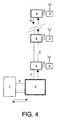
- Figure 4 shows the physical connection between the entities of the proposed optical fibre connection system described in figure 1.
- the topology of the optical fibre layout is a ring.
- the connections correspond to a group of two fibres as is detailed in figure 4, since the return from the uplink or downlink connection need not go back to the base station transponder, since communication with any transponder is possible.
- figure 4 shows the simplest case in which the return from the uplink and the downlink connection need not be to the base station transponder, this can be of interest in various situations, forming a true optical fibre ring.
- the ring configuration is useful for the purpose of monitoring the optical transmission quality.
- the signal sent by the transponder of the base station (3) will return again to said transponder after having passed through all the remote antenna transponders and the entire optical fibre downlink ring.
- a signal, a reference carrier could have been injected for quality tests. In any case, from the analysis of the received signal the quality of the operation of the amplifiers and the signal losses in the fibre system can be checked.
- the ring configuration allows incorporation of protection mechanisms against failures, such as the physical breaking of the fibre ring or a fault in any intermediate optical amplifier.
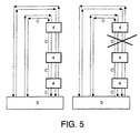
- Figure 5 shows the 1+1 protection mechanism between the entities of the proposed optical fibre connection system described in figure 1.
- All the transponders transmit simultaneously over two different optical fibres and in opposing directions, both for the uplink connection and the downlink.
- the receivers receive from a single optical fibre termed the main optical fibre, but at the same time they monitor the quality of the signal received via the other optical fibre termed the standby optical fibre. In the event of detecting a failure in reception from the main optical fibre, changeover to the standby takes place in reception.
Landscapes
- Engineering & Computer Science (AREA)
- Computer Networks & Wireless Communication (AREA)
- Signal Processing (AREA)
- Physics & Mathematics (AREA)
- Electromagnetism (AREA)
- Mobile Radio Communication Systems (AREA)
- Optical Communication System (AREA)
- Small-Scale Networks (AREA)
Abstract
- one or several base stations.
- one or several remote antennas.
- one or several base station transponders.
- one or several remote antenna transponders.
Description
- This invention describes an optical fibre connection system using DWDM/SCM hybrid techniques between base stations and remote antennas in a radiocommunications system, as well as access method.
- The object of this invention is to provide a system of transparent connection between base stations and remote antennas for a radiocommunications system by optical fibre networks in point to multipoint structure with 1+1 protection mechanisms.
- The field of application is that of telecommunications in general, and more specifically in the cellular communications systems such as GSM, DCS and UMTS.
- The technique of radio over fibre (ROF) is known for the connection between base stations and remote antennas in cellular communications. In it, the output radiofrequency signal of a base station modulates a laser source, the resulting light signal being transmitted through an optical fibre to a remote antenna where a photodiode transforms said optical signal once more into an electrical radiofrequency signal before being transmitted by the remote antenna. In like fashion, the radiofrequency signal received by a remote antenna is transmitted to the base station by means of an optical fibre, for which an electro-optical conversion is necessary.
- Various systems of the radio-over-fibre type are known, which are characterised by the number of optical fibres employed, the number of carriers transmitted by the fibre, the maximum length of the optical fibres used, etc. Various multinational companies market these ROF systems for cellular applications.
- ROF systems are known which use SCM multiplexing in the downlink direction and TDMA techniques in the uplink direction. Systems are also known which use two different optical carriers to separate the uplink and the downlink directions.
Using DWDM/SCM hybrid techniques is not known in the state of the art for the connection over optical fibre between base stations and remote antennas in a radiocommunications system, such as is an object of the proposed invention. - The present invention discloses the architecture of the optical fibre connection system using DWDM/SCM hybrid techniques between base stations and remote antennas in a radiocommunications system, and which is constituted by a base station, one or several remote antennas, a base station transponder and one or several remote antenna transponders.
- Specifically, the present system is configured so that the DWDM technique is used in the uplink direction from the remote antennas to the base stations and the SCM in the downlink direction from the base stations to the remote antennas.
- A complete system includes typically the presence of several base stations and associated transponders, remote antennas and associated transponders, and remote radio terminals.
- The base station will communicate with the remote antennas through a connection via optical fibre, using the base station transponders and remote antenna to carry out the necessary electro-optical conversions. The transponders are interconnected forming an optical fibre network in ring configuration.
- The base station will be in charge of transmitting and receiving all the communication channels in accordance with the selected radiocommunications standard (for example GSM, DCS, UMTS).
- The remote antenna is the physical device for transmission and reception of the radio signal through which the terminals will be connected to the rest of the radiofrequency communications system.
- Among the main characteristics of the optical fibre connection system using DWDM/SCM hybrid techniques between base stations and remote antennas in a radiocommunications system, are:
- The radiofrequency interfaces of one or several base stations are connected to a network element termed base station transponder, which constitutes the head-end node of an optical fibre network.
- The radiofrequency interface of each remote antenna is connected to a network element termed remote antenna transponder, which constitutes an element of the optical fibre network.
- All the transponders are elements of an optical fibre network in ring configuration, through which they are interconnected. Although the optical fibre network in ring configuration is that preferred in the proposed invention, the invention is also applicable to other topologies such as tree networks or ring-tree hybrid networks.
- The optical fibre network allows incorporation of a 1+1 protection mechanism, which maintains the integrity of the communication through the optical fibre network in the event of a breakage or fault in some point of said network.
- In the downlink direction from the base stations to the remote antennas, the signal of the base station is constituted as a group of carriers separated in frequency, which signal modulates a single optical carrier in the base station transponder (for example in the window of 1550 nm).
- In the uplink direction from the remote antennas to the base station, each antenna signal is modulated by the associated transponder on a single different carrier for each transponder.
- Just as in any optical fibre network, optical amplifiers will be used if necessary to compensate for the signal losses in the transmission through the optical fibre network, both in the uplink direction and in the downlink.
- The extraction of signals in the remote transponders is carried out by means of a passive optical coupler.
- In the downlink direction a signalling channel is transmitted on a previously specified carrier. This channel informs each remote transponder of the carriers assigned to the associated remote antenna.
- It is possible to reuse or share the optical fibre network with other services foreign to the system described by means of wave division multiplexers which separate the optical bands used by each system.
-
- Figure 1 shows the architecture of the optical fibre connection system using DWDM/SCM hybrid techniques between base stations and remote antennas in a cellular communications system.
- Figure 2 shows the architecture of the electro-optical transponder module near to the base station.
- Figure 3 shows the architecture of the module electro-optical transponder near to the remote antenna.
- Figure 4 shows the physical connection between the entities of the proposed optical fibre connection system.
- Figure 5 shows the 1+1 protection mechanism between the entities of the proposed optical fibre connection system.
-
- Figure 1 shows the entities involved in the architecture of the optical fibre connection system using DWDM/SCM hybrid techniques between base stations and remote antennas in a radiocommunications system: base station (1), remote antenna (2), base station transponder (3) and remote antenna transponder (4).
- One or several remote antennas (2) can be present with their corresponding associated antenna transponders (3). A complete system includes typically the presence of several base stations (1) and associated transponders (3), remote antennas (2) and associated transponders (4), and remote radio terminals. In figure 1 all the elements mentioned are not detailed, this not being considered necessary from the point of view of describing the invention.
- The base station (1) will communicate with the remote antennas (2) through a connection via optical fibre. For this the electro-optical conversion is necessary between electrical signals coming from the base stations and remote antennas, and the optical signals used in the optical fibres, which is carried out by the base station transponders (3) and the remote antenna transponders (4). The transponders (3 and 4) are interconnected forming an optical fibre network in ring configuration.
- The base station (1) will be in charge of transmitting and receiving all the communication channels in accordance with the selected radiocommunications standard (for example GSM, DCS, UMTS). The base station (1) communicates with the base station transponder (3) to which it is linked via coaxial cable (A) by means of electrical communication at radiofrequency.
The remote antenna (2) is the physical device for transmitting and receiving the radio signal through which the terminals will be connected to the rest of the radiofrequency communications system. The remote antenna (2) communicates with the remote antenna transponder (4) to which it is linked via coaxial cable (or optical fibre) (B) by means of electrical communication at radiofrequency. - The purpose of the base station transponder (3) is the adaptation of the electrical signals of the interface with the associated base station (1) and the optical signals in the optical fibre interfaces (C) used by the network of transponders (3 and 4).
- The purpose of the remote antenna transponder (4) is the adaptation of the signals of the interface with the remote antenna (2) and the optical signals in the optical fibre interfaces (C) used by the network of transponders (3 and 4).
- Among the main characteristics of the optical fibre connection system using DWDM/SCM hybrid techniques between base stations and remote antennas in a radiocommunications system, are:
- The radiofrequency interfaces of one or several base stations (1) are connected to a network element termed base station transponder (3), which constitutes the head-end node of an optical fibre network.
- The radiofrequency interface of each remote antenna (2) is connected to a network element termed remote antenna transponder (4), which constitutes an element of the optical fibre network.
- All the transponders (3 and 4) are elements of an optical fibre network in ring configuration, through which they are interconnected. Although the optical fibre network in ring configuration is that preferred in the proposed invention, the invention is also applicable to other topologies such as tree networks or ring-tree hybrid networks.
- The optical fibre network allows the incorporation of a 1+1 protection mechanism, which maintains the integrity of the communication through the optical fibre network in the event of a breakage or fault in some point of said network.
- In the downlink direction from the base station to the remote antennas, the signal of the base station is constituted as a group of carriers separated in frequency, which modulates a single optical carrier in the base station transponder (for example in the window of 1550 nm).
- In the uplink direction from the remote antennas to the base station, each antenna signal is modulated by the associated transponder on a single different carrier for each transponder.
- Just as in any optical fibre network, optical amplifiers will be used if necessary to compensate for the signal losses in the transmission through the optical fibre network, both in the uplink direction and in the downlink.
- The extraction of signals in the remote transponders (4) is carried out by means of a passive optical coupler.
- In the downlink direction a signalling channel is transmitted on a previously specified carrier. This channel informs each remote transponder (4) of the carriers assigned to the associated remote antenna (2).
- It is possible to reuse or share the optical fibre network with other services foreign to the system described by means of wave division multiplexers which separate the optical bands used by each system.
- In figure 1, the letters A to C denote the interfaces between the various entities. These interfaces are:
- A- Interface between the base station (1) and the base station transponder (3). This interface is via coaxial cable by means of electrical communication at radiofrequency. The radiofrequency signal will be constituted by the group of communications to or from all the remote antennas (4).
- B- Interface between the remote antenna (2) and the remote antenna transponder (4). This interface is via coaxial cable (or optical fibre) by means of electrical communication at radiofrequency. The radiofrequency signal will be constituted only by the communication assigned to the remote antenna (4).
- C- Optical fibre interface between all the transponder elements (3 and 4) of the optical network. It can be in a ring, linear, tree-shaped or any other. It can have 1+1 protection mechanisms incorporated.
-
- Figure 2 shows the entities involved in the architecture of the electro-optical transponder module (3) near to the base station: signalling channel generator (5), band-pass filters (6), amplifiers (7), reference frequency generator (8), protection circuits (9), converters or mixers (10), carrier synthesizers (11), channel mixer or adder (12), laser transmitter (13), optical receiver amplifier (14), WDM wavelength demultiplexer (15), photodetectors (16), receiver amplifiers (17), signal separators (18) and control module (19).
- In the downlink connection to the remote antennas (2), the base station transponder (3) comprises a group of frequency converter chains (10) which translate each of the assigned radiofrequency channels (for example GSM, DCS, UMTS) to the channel assigned in the optical fibre transmission. Each of the channels will be located on a different sub-carrier (11), and all of them will form the carrier which modulates the laser transmission (13).
- In the uplink connection to the base station (1), the different channels coming from each remote antenna (2) are separated in the wavelength demultiplexer (15). Each channel is photodetected (16) and amplified (17), a radiofrequency signal being obtained which is a replica of that sent by the corresponding remote antenna (2).
- Although it is not indicated in the figure, each reception channel extracts a telemetry signal coming from the remote antenna transponder (4) which contains information on transmission alarms.
- The control module (19) carries out, among other functions, the monitoring of the frequencies of the sub-carriers employed, information of the signalling channel and information on alarms. This circuit communicates with the exterior through a monitoring interface.
- Figure 3 shows the entities involved in the architecture of the electro-optical transponder module near to the remote antenna: the uplink connection optical amplifier (20), the downlink connection optical amplifier (21), the uplink connection coupler (22), the downlink connection coupler (23), photodetector (24), receiver amplifier (25), reception filter for signalling channel (26), the signalling channel receiver (27), reception filter for the reference clock recovery circuit (28), reference clock recovery circuit (29), intermediate frequency mixer (30), intermediate frequency filter (31), secondary mixer (32), secondary filter (34), frequency synthesizers (33), channel mixer or adder (35 and 36), antenna laser transmitters (37 and 38), antenna photodetector (39), amplifier (40), laser transmitter (41) and control module (42).
- The remote antenna transponder connects the two optical fibres (C) of the transponder ring to the remote antenna module through also, for example, another optical fibre interface.
- The signal coming from the base station (1) through the downlink connection of the optical fibre ring is inserted in an optical coupler (23) from which the input signal to the remote antenna transponder (4) is extracted. This signal is photodetected (24) and amplified (25). The radiofrequency carriers are translated into the required bands through the mixer assembly (30 and 32), filters (31 and 34) and synthesizers (33). All these bands modulate a laser transmitter which is applied to the interface with the remote antenna (2).
- The control circuit (42) extracts its instructions from the signalling channel (27), and the reference clock signal is extracted by the reference clock extractor circuit (29).
- In the uplink direction to the base station (1), the situation is similar except in this case frequency conversions are not necessary. The optical signal is translated transparently from the remote antenna interface (for example 1300 nm) to the interface with the optical fibre ring of the transponder network (for example 1500 nm).
- The use of amplifiers in the optical fibre ring network of the transponders, is necessary to avoid an excessive loss of power in the signal transmitted through the optical fibres. By way of example, for GSM signals it is necessary to use amplifiers every fifteen remote antenna transponders (4). Also, in the uplink direction, to prevent the signals coming from the remote antennas having very different power levels, the coupling factor in the transponder couplers can be different between the different transponder groups.
- Figure 4 shows the physical connection between the entities of the proposed optical fibre connection system described in figure 1.
- Just as has been described in figure 1, the topology of the optical fibre layout is a ring. However, from the physical point of view, the connections correspond to a group of two fibres as is detailed in figure 4, since the return from the uplink or downlink connection need not go back to the base station transponder, since communication with any transponder is possible.
- Although figure 4 shows the simplest case in which the return from the uplink and the downlink connection need not be to the base station transponder, this can be of interest in various situations, forming a true optical fibre ring.
- In the first place the ring configuration is useful for the purpose of monitoring the optical transmission quality. In the downlink connection, the signal sent by the transponder of the base station (3) will return again to said transponder after having passed through all the remote antenna transponders and the entire optical fibre downlink ring. In the uplink connection a signal, a reference carrier, could have been injected for quality tests. In any case, from the analysis of the received signal the quality of the operation of the amplifiers and the signal losses in the fibre system can be checked.
- In the second place the ring configuration allows incorporation of protection mechanisms against failures, such as the physical breaking of the fibre ring or a fault in any intermediate optical amplifier.
- Figure 5 shows the 1+1 protection mechanism between the entities of the proposed optical fibre connection system described in figure 1.
- All the transponders transmit simultaneously over two different optical fibres and in opposing directions, both for the uplink connection and the downlink. The receivers receive from a single optical fibre termed the main optical fibre, but at the same time they monitor the quality of the signal received via the other optical fibre termed the standby optical fibre. In the event of detecting a failure in reception from the main optical fibre, changeover to the standby takes place in reception.
-
- DCS
- Digital Cellular System of mobile telecommunications which uses the 1800 MHz frequency band.
- DWDM
- Dense Wavelength Division Multiplexing.
- GSM
- Radiofrequency cellular communications system standardized and regulated by ETSI (Global System for Mobile communication).
- MHz
- Megahertz. Electric frequency unit of measurement.
- Nm
- Nanometre(s). Wavelength unit of measurement.
- ROF
- Radio over fibre.
- SCM
- Sub-Carrier Multiplexing.
- TDMA
- Time division multiple access. System employed to separate the different user data channels as for example in the GSM cellular communication system.
- UMTS
- Cellular universal mobile telecommunications system. Third generation cellular communications system.
- WDM
- Wavelength Division Multiplexing.
Claims (16)
- Optical fibre connection system using DWDM/SCM hybrid techniques between base stations and remote antennas in a radiocommunications system characterised by using DWDM in the uplink direction from the remote antennas to the base stations and SCM in the downlink direction from the base stations to the remote antennas.
- Optical fibre connection system using DWDM/SCM hybrid techniques between base stations and remote antennas in a radiocommunications system according to claim 1 characterised by having base stations for radiocommunications.
- Optical fibre connection system using DWDM/SCM hybrid techniques between base stations and remote antennas in a radiocommunications system according to claims 1 and 2 characterised by having transponders which match the optical interfaces with the optical fibre network using DWDM/SCM hybrid techniques to the electrical interfaces with the base stations.
- Optical fibre connection system using DWDM/SCM hybrid techniques between base stations and remote antennas in a radiocommunications system according to claim 1 characterised by having remote antennas for radiocommunications.
- Optical fibre connection system using DWDM/SCM hybrid techniques between base stations and remote antennas in a radiocommunications system according to claims 1 and 4 characterised by having transponders which match the optical interfaces with the optical fibre network using DWDM/SCM hybrid techniques to the electrical interfaces with the remote antennas.
- Optical fibre connection system using DWDM/SCM hybrid techniques between base stations and remote antennas in a radiocommunications system according to claims 1 to 5 characterised by using 1+1 protection techniques in the optical fibre links between the base stations and the remote antennas.
- Optical fibre connection system using DWDM/SCM hybrid techniques between base stations and remote antennas in a radiocommunications system according to claims 1 to 5 characterised by using optical amplifiers or regenerators in the optical fibre network which allow compensation for the signal attenuation suffered in transmission.
- Optical fibre connection system using DWDM/SCM hybrid techniques between base stations and remote antennas in a radiocommunications system according to claims 1 to 5 characterised by reusing or sharing the optical fibre network with services different to the proposed system.
- Access method of the optical fibre connection system using DWDM/SCM hybrid techniques between base stations and remote antennas in a radiocommunications system characterised by using DWDM in the uplink direction from the remote antennas to the base stations and SCM in the downlink direction from the base stations to the remote antennas.
- Access method of the optical fibre connection system using DWDM/SCM hybrid techniques between base stations and remote antennas in a radiocommunications system according to claim 9 characterised by having base stations for radiocommunications.
- Access method of the optical fibre connection system using DWDM/SCM hybrid techniques between base stations and remote antennas in a radiocommunications system according to claim 9 characterised by having transponders which match the optical interfaces with the optical fibre network using DWDM/SCM hybrid techniques to the electrical interfaces with the base stations.
- Access method of the optical fibre connection system using DWDM/SCM hybrid techniques between base stations and remote antennas in a radiocommunications system according to claims 9 and 10 characterised by having remote antennas for radiocommunications.
- Access method of the optical fibre connection system using DWDM/SCM hybrid techniques between base stations and remote antennas in a radiocommunications system according to claims 9, 10 and 12 characterised by having transponders which match the optical interfaces with the optical fibre network using DWDM/SCM hybrid techniques to the electrical interfaces with the remote antennas.
- Access method of the optical fibre connection system using DWDM/SCM hybrid techniques between base stations and remote antennas in a radiocommunications system according to claims 9 to 13 characterised by using 1+1 protection techniques in the optical fibre connections between the base stations and the remote antennas.
- Access method of the optical fibre connection system using DWDM/SCM hybrid techniques between base stations and remote antennas in a radiocommunications system according to claims 9 to 13 characterised by using optical amplifiers or regenerators in the optical fibre network which allow compensation for the signal attenuation suffered in transmission.
- Access method of the optical fibre connection system using DWDM/SCM hybrid techniques between base stations and remote antennas in a radiocommunications system according to claims 9 to 13 characterised by reusing or sharing the optical fibre network with services different to the proposed system.
Applications Claiming Priority (3)
| Application Number | Priority Date | Filing Date | Title |
|---|---|---|---|
| ES200200860A ES2198206B2 (en) | 2002-04-12 | 2002-04-12 | CONNECTION SYSTEM THROUGH OPTICAL FIBER USING DWDM / SCM HYBRID TECHNIQUES BETWEEN BASE STATIONS AND REMOTE AERIALS IN A RADIOCOMMUNICATION SYSTEM, AS WELL AS ACCESS METHOD. |
| ES200200860 | 2002-04-12 | ||
| PCT/ES2003/000168 WO2003088518A1 (en) | 2002-04-12 | 2003-04-11 | Access method and connection system by means of optical fiber using dwdm/scm hybrid techniques between base stations and remote antennas in a radiocommunication system |
Publications (1)
| Publication Number | Publication Date |
|---|---|
| EP1501206A1 true EP1501206A1 (en) | 2005-01-26 |
Family
ID=29225790
Family Applications (1)
| Application Number | Title | Priority Date | Filing Date |
|---|---|---|---|
| EP03720572A Withdrawn EP1501206A1 (en) | 2002-04-12 | 2003-04-11 | Access method and connection system by means of optical fiber using dwdm/scm hybrid techniques between base stations and remote antennas in a radiocommunication system |
Country Status (9)
| Country | Link |
|---|---|
| EP (1) | EP1501206A1 (en) |
| AR (1) | AR039621A1 (en) |
| AU (1) | AU2003224163A1 (en) |
| ES (1) | ES2198206B2 (en) |
| GT (1) | GT200300085A (en) |
| MA (1) | MA27462A1 (en) |
| MX (1) | MXPA04010689A (en) |
| PE (1) | PE20040020A1 (en) |
| WO (1) | WO2003088518A1 (en) |
Cited By (55)
| Publication number | Priority date | Publication date | Assignee | Title |
|---|---|---|---|---|
| WO2007142805A2 (en) | 2006-05-19 | 2007-12-13 | Corning Cable Systems Llc | Fiber optic cable and fiber optic cable assembly for wireless access |
| CN100379305C (en) * | 2005-10-21 | 2008-04-02 | 芯通科技(成都)有限公司 | Ring connection method and intermediate frequency interface structure of wireless communication base station/transceiver |
| US7590354B2 (en) | 2006-06-16 | 2009-09-15 | Corning Cable Systems Llc | Redundant transponder array for a radio-over-fiber optical fiber cable |
| US7627250B2 (en) | 2006-08-16 | 2009-12-01 | Corning Cable Systems Llc | Radio-over-fiber transponder with a dual-band patch antenna system |
| CN101197746B (en) * | 2007-12-26 | 2010-06-16 | 中兴通讯股份有限公司 | Base station ring-shaped network method in GSM system |
| US7787823B2 (en) | 2006-09-15 | 2010-08-31 | Corning Cable Systems Llc | Radio-over-fiber (RoF) optical fiber cable system with transponder diversity and RoF wireless picocellular system using same |
| US7848654B2 (en) | 2006-09-28 | 2010-12-07 | Corning Cable Systems Llc | Radio-over-fiber (RoF) wireless picocellular system with combined picocells |
| US8111998B2 (en) | 2007-02-06 | 2012-02-07 | Corning Cable Systems Llc | Transponder systems and methods for radio-over-fiber (RoF) wireless picocellular systems |
| US8175459B2 (en) | 2007-10-12 | 2012-05-08 | Corning Cable Systems Llc | Hybrid wireless/wired RoF transponder and hybrid RoF communication system using same |
| US8275265B2 (en) | 2010-02-15 | 2012-09-25 | Corning Cable Systems Llc | Dynamic cell bonding (DCB) for radio-over-fiber (RoF)-based networks and communication systems and related methods |
| EP2611048A1 (en) * | 2011-12-30 | 2013-07-03 | Nokia Siemens Networks Oy | Multi-channel transmitter for coherent udwdm networks and method for generating a multi-channel signal |
| US8548330B2 (en) | 2009-07-31 | 2013-10-01 | Corning Cable Systems Llc | Sectorization in distributed antenna systems, and related components and methods |
| US8644844B2 (en) | 2007-12-20 | 2014-02-04 | Corning Mobileaccess Ltd. | Extending outdoor location based services and applications into enclosed areas |
| US8867919B2 (en) | 2007-07-24 | 2014-10-21 | Corning Cable Systems Llc | Multi-port accumulator for radio-over-fiber (RoF) wireless picocellular systems |
| US8873585B2 (en) | 2006-12-19 | 2014-10-28 | Corning Optical Communications Wireless Ltd | Distributed antenna system for MIMO technologies |
| US9037143B2 (en) | 2010-08-16 | 2015-05-19 | Corning Optical Communications LLC | Remote antenna clusters and related systems, components, and methods supporting digital data signal propagation between remote antenna units |
| US9042732B2 (en) | 2010-05-02 | 2015-05-26 | Corning Optical Communications LLC | Providing digital data services in optical fiber-based distributed radio frequency (RF) communication systems, and related components and methods |
| US9112611B2 (en) | 2009-02-03 | 2015-08-18 | Corning Optical Communications LLC | Optical fiber-based distributed antenna systems, components, and related methods for calibration thereof |
| US9178635B2 (en) | 2014-01-03 | 2015-11-03 | Corning Optical Communications Wireless Ltd | Separation of communication signal sub-bands in distributed antenna systems (DASs) to reduce interference |
| US9184843B2 (en) | 2011-04-29 | 2015-11-10 | Corning Optical Communications LLC | Determining propagation delay of communications in distributed antenna systems, and related components, systems, and methods |
| US9219879B2 (en) | 2009-11-13 | 2015-12-22 | Corning Optical Communications LLC | Radio-over-fiber (ROF) system for protocol-independent wired and/or wireless communication |
| US9240835B2 (en) | 2011-04-29 | 2016-01-19 | Corning Optical Communications LLC | Systems, methods, and devices for increasing radio frequency (RF) power in distributed antenna systems |
| US9247543B2 (en) | 2013-07-23 | 2016-01-26 | Corning Optical Communications Wireless Ltd | Monitoring non-supported wireless spectrum within coverage areas of distributed antenna systems (DASs) |
| US9258052B2 (en) | 2012-03-30 | 2016-02-09 | Corning Optical Communications LLC | Reducing location-dependent interference in distributed antenna systems operating in multiple-input, multiple-output (MIMO) configuration, and related components, systems, and methods |
| US9325429B2 (en) | 2011-02-21 | 2016-04-26 | Corning Optical Communications LLC | Providing digital data services as electrical signals and radio-frequency (RF) communications over optical fiber in distributed communications systems, and related components and methods |
| US9357551B2 (en) | 2014-05-30 | 2016-05-31 | Corning Optical Communications Wireless Ltd | Systems and methods for simultaneous sampling of serial digital data streams from multiple analog-to-digital converters (ADCS), including in distributed antenna systems |
| US9385810B2 (en) | 2013-09-30 | 2016-07-05 | Corning Optical Communications Wireless Ltd | Connection mapping in distributed communication systems |
| US9420542B2 (en) | 2014-09-25 | 2016-08-16 | Corning Optical Communications Wireless Ltd | System-wide uplink band gain control in a distributed antenna system (DAS), based on per band gain control of remote uplink paths in remote units |
| US9455784B2 (en) | 2012-10-31 | 2016-09-27 | Corning Optical Communications Wireless Ltd | Deployable wireless infrastructures and methods of deploying wireless infrastructures |
| US9525488B2 (en) | 2010-05-02 | 2016-12-20 | Corning Optical Communications LLC | Digital data services and/or power distribution in optical fiber-based distributed communications systems providing digital data and radio frequency (RF) communications services, and related components and methods |
| US9525472B2 (en) | 2014-07-30 | 2016-12-20 | Corning Incorporated | Reducing location-dependent destructive interference in distributed antenna systems (DASS) operating in multiple-input, multiple-output (MIMO) configuration, and related components, systems, and methods |
| US9531452B2 (en) | 2012-11-29 | 2016-12-27 | Corning Optical Communications LLC | Hybrid intra-cell / inter-cell remote unit antenna bonding in multiple-input, multiple-output (MIMO) distributed antenna systems (DASs) |
| US9602210B2 (en) | 2014-09-24 | 2017-03-21 | Corning Optical Communications Wireless Ltd | Flexible head-end chassis supporting automatic identification and interconnection of radio interface modules and optical interface modules in an optical fiber-based distributed antenna system (DAS) |
| US9621293B2 (en) | 2012-08-07 | 2017-04-11 | Corning Optical Communications Wireless Ltd | Distribution of time-division multiplexed (TDM) management services in a distributed antenna system, and related components, systems, and methods |
| US9647758B2 (en) | 2012-11-30 | 2017-05-09 | Corning Optical Communications Wireless Ltd | Cabling connectivity monitoring and verification |
| US9661781B2 (en) | 2013-07-31 | 2017-05-23 | Corning Optical Communications Wireless Ltd | Remote units for distributed communication systems and related installation methods and apparatuses |
| US9673904B2 (en) | 2009-02-03 | 2017-06-06 | Corning Optical Communications LLC | Optical fiber-based distributed antenna systems, components, and related methods for calibration thereof |
| US9681313B2 (en) | 2015-04-15 | 2017-06-13 | Corning Optical Communications Wireless Ltd | Optimizing remote antenna unit performance using an alternative data channel |
| US9715157B2 (en) | 2013-06-12 | 2017-07-25 | Corning Optical Communications Wireless Ltd | Voltage controlled optical directional coupler |
| US9729267B2 (en) | 2014-12-11 | 2017-08-08 | Corning Optical Communications Wireless Ltd | Multiplexing two separate optical links with the same wavelength using asymmetric combining and splitting |
| US9730228B2 (en) | 2014-08-29 | 2017-08-08 | Corning Optical Communications Wireless Ltd | Individualized gain control of remote uplink band paths in a remote unit in a distributed antenna system (DAS), based on combined uplink power level in the remote unit |
| US9775123B2 (en) | 2014-03-28 | 2017-09-26 | Corning Optical Communications Wireless Ltd. | Individualized gain control of uplink paths in remote units in a distributed antenna system (DAS) based on individual remote unit contribution to combined uplink power |
| US9807700B2 (en) | 2015-02-19 | 2017-10-31 | Corning Optical Communications Wireless Ltd | Offsetting unwanted downlink interference signals in an uplink path in a distributed antenna system (DAS) |
| US9948349B2 (en) | 2015-07-17 | 2018-04-17 | Corning Optical Communications Wireless Ltd | IOT automation and data collection system |
| US9974074B2 (en) | 2013-06-12 | 2018-05-15 | Corning Optical Communications Wireless Ltd | Time-division duplexing (TDD) in distributed communications systems, including distributed antenna systems (DASs) |
| US10096909B2 (en) | 2014-11-03 | 2018-10-09 | Corning Optical Communications Wireless Ltd. | Multi-band monopole planar antennas configured to facilitate improved radio frequency (RF) isolation in multiple-input multiple-output (MIMO) antenna arrangement |
| US10110308B2 (en) | 2014-12-18 | 2018-10-23 | Corning Optical Communications Wireless Ltd | Digital interface modules (DIMs) for flexibly distributing digital and/or analog communications signals in wide-area analog distributed antenna systems (DASs) |
| US10128951B2 (en) | 2009-02-03 | 2018-11-13 | Corning Optical Communications LLC | Optical fiber-based distributed antenna systems, components, and related methods for monitoring and configuring thereof |
| US10136200B2 (en) | 2012-04-25 | 2018-11-20 | Corning Optical Communications LLC | Distributed antenna system architectures |
| US10135533B2 (en) | 2014-11-13 | 2018-11-20 | Corning Optical Communications Wireless Ltd | Analog distributed antenna systems (DASS) supporting distribution of digital communications signals interfaced from a digital signal source and analog radio frequency (RF) communications signals |
| US10187151B2 (en) | 2014-12-18 | 2019-01-22 | Corning Optical Communications Wireless Ltd | Digital-analog interface modules (DAIMs) for flexibly distributing digital and/or analog communications signals in wide-area analog distributed antenna systems (DASs) |
| US10236924B2 (en) | 2016-03-31 | 2019-03-19 | Corning Optical Communications Wireless Ltd | Reducing out-of-channel noise in a wireless distribution system (WDS) |
| US10560214B2 (en) | 2015-09-28 | 2020-02-11 | Corning Optical Communications LLC | Downlink and uplink communication path switching in a time-division duplex (TDD) distributed antenna system (DAS) |
| US10659163B2 (en) | 2014-09-25 | 2020-05-19 | Corning Optical Communications LLC | Supporting analog remote antenna units (RAUs) in digital distributed antenna systems (DASs) using analog RAU digital adaptors |
| US11178609B2 (en) | 2010-10-13 | 2021-11-16 | Corning Optical Communications LLC | Power management for remote antenna units in distributed antenna systems |
Families Citing this family (3)
| Publication number | Priority date | Publication date | Assignee | Title |
|---|---|---|---|---|
| ES2239490B1 (en) * | 2002-12-02 | 2006-12-01 | Angel Iglesias, S.A. | RADIO FREQUENCY SIGNAL TRANSMISSION SYSTEM THROUGH OPTICAL FIBER IN CASCADA. |
| CN100370716C (en) * | 2004-02-23 | 2008-02-20 | 华为技术有限公司 | Distributed Base Station Ring Networking System and Its Data Interaction Method |
| CN100525236C (en) | 2005-12-19 | 2009-08-05 | 华为技术有限公司 | Optic network and radio communication network interconnection system and its communication method |
Family Cites Families (5)
| Publication number | Priority date | Publication date | Assignee | Title |
|---|---|---|---|---|
| DE4019224A1 (en) * | 1990-06-15 | 1991-12-19 | Standard Elektrik Lorenz Ag | RADIO NEWS TRANSMISSION SYSTEM, IN PARTICULAR CELLULAR MOBILE RADIO SYSTEM |
| EP0762674A3 (en) * | 1995-09-08 | 2001-03-21 | Siemens Aktiengesellschaft | Method and circuit to transmit received signals from an antenna to a base station of a radio system |
| KR100376298B1 (en) * | 1999-09-13 | 2003-03-17 | 가부시끼가이샤 도시바 | Radio communication system |
| US6490727B1 (en) * | 1999-10-07 | 2002-12-03 | Harmonic, Inc. | Distributed termination system for two-way hybrid networks |
| GB2370170B (en) * | 2000-12-15 | 2003-01-29 | Ntl Group Ltd | Signal transmission systems |
-
2002
- 2002-04-12 ES ES200200860A patent/ES2198206B2/en not_active Expired - Fee Related
-
2003
- 2003-04-08 AR ARP030101228A patent/AR039621A1/en active IP Right Grant
- 2003-04-09 PE PE2003000360A patent/PE20040020A1/en not_active Application Discontinuation
- 2003-04-10 GT GT200300085A patent/GT200300085A/en unknown
- 2003-04-11 AU AU2003224163A patent/AU2003224163A1/en not_active Abandoned
- 2003-04-11 MX MXPA04010689A patent/MXPA04010689A/en active IP Right Grant
- 2003-04-11 EP EP03720572A patent/EP1501206A1/en not_active Withdrawn
- 2003-04-11 WO PCT/ES2003/000168 patent/WO2003088518A1/en not_active Ceased
-
2004
- 2004-11-08 MA MA27937A patent/MA27462A1/en unknown
Non-Patent Citations (1)
| Title |
|---|
| See references of WO03088518A1 * |
Cited By (100)
| Publication number | Priority date | Publication date | Assignee | Title |
|---|---|---|---|---|
| CN100379305C (en) * | 2005-10-21 | 2008-04-02 | 芯通科技(成都)有限公司 | Ring connection method and intermediate frequency interface structure of wireless communication base station/transceiver |
| WO2007142805A2 (en) | 2006-05-19 | 2007-12-13 | Corning Cable Systems Llc | Fiber optic cable and fiber optic cable assembly for wireless access |
| WO2007142805A3 (en) * | 2006-05-19 | 2008-03-06 | Corning Cable Sys Llc | Fiber optic cable and fiber optic cable assembly for wireless access |
| JP2009537964A (en) * | 2006-05-19 | 2009-10-29 | コーニング ケーブル システムズ リミテッド ライアビリティ カンパニー | Fiber optic cable and fiber optic cable assembly for wireless access |
| US8472767B2 (en) | 2006-05-19 | 2013-06-25 | Corning Cable Systems Llc | Fiber optic cable and fiber optic cable assembly for wireless access |
| US7590354B2 (en) | 2006-06-16 | 2009-09-15 | Corning Cable Systems Llc | Redundant transponder array for a radio-over-fiber optical fiber cable |
| US7627250B2 (en) | 2006-08-16 | 2009-12-01 | Corning Cable Systems Llc | Radio-over-fiber transponder with a dual-band patch antenna system |
| US7787823B2 (en) | 2006-09-15 | 2010-08-31 | Corning Cable Systems Llc | Radio-over-fiber (RoF) optical fiber cable system with transponder diversity and RoF wireless picocellular system using same |
| US7848654B2 (en) | 2006-09-28 | 2010-12-07 | Corning Cable Systems Llc | Radio-over-fiber (RoF) wireless picocellular system with combined picocells |
| US9130613B2 (en) | 2006-12-19 | 2015-09-08 | Corning Optical Communications Wireless Ltd | Distributed antenna system for MIMO technologies |
| US8873585B2 (en) | 2006-12-19 | 2014-10-28 | Corning Optical Communications Wireless Ltd | Distributed antenna system for MIMO technologies |
| US8111998B2 (en) | 2007-02-06 | 2012-02-07 | Corning Cable Systems Llc | Transponder systems and methods for radio-over-fiber (RoF) wireless picocellular systems |
| US8867919B2 (en) | 2007-07-24 | 2014-10-21 | Corning Cable Systems Llc | Multi-port accumulator for radio-over-fiber (RoF) wireless picocellular systems |
| US8175459B2 (en) | 2007-10-12 | 2012-05-08 | Corning Cable Systems Llc | Hybrid wireless/wired RoF transponder and hybrid RoF communication system using same |
| US8718478B2 (en) | 2007-10-12 | 2014-05-06 | Corning Cable Systems Llc | Hybrid wireless/wired RoF transponder and hybrid RoF communication system using same |
| US8644844B2 (en) | 2007-12-20 | 2014-02-04 | Corning Mobileaccess Ltd. | Extending outdoor location based services and applications into enclosed areas |
| CN101197746B (en) * | 2007-12-26 | 2010-06-16 | 中兴通讯股份有限公司 | Base station ring-shaped network method in GSM system |
| US10128951B2 (en) | 2009-02-03 | 2018-11-13 | Corning Optical Communications LLC | Optical fiber-based distributed antenna systems, components, and related methods for monitoring and configuring thereof |
| US9900097B2 (en) | 2009-02-03 | 2018-02-20 | Corning Optical Communications LLC | Optical fiber-based distributed antenna systems, components, and related methods for calibration thereof |
| US9673904B2 (en) | 2009-02-03 | 2017-06-06 | Corning Optical Communications LLC | Optical fiber-based distributed antenna systems, components, and related methods for calibration thereof |
| US9112611B2 (en) | 2009-02-03 | 2015-08-18 | Corning Optical Communications LLC | Optical fiber-based distributed antenna systems, components, and related methods for calibration thereof |
| US10153841B2 (en) | 2009-02-03 | 2018-12-11 | Corning Optical Communications LLC | Optical fiber-based distributed antenna systems, components, and related methods for calibration thereof |
| US8548330B2 (en) | 2009-07-31 | 2013-10-01 | Corning Cable Systems Llc | Sectorization in distributed antenna systems, and related components and methods |
| US9485022B2 (en) | 2009-11-13 | 2016-11-01 | Corning Optical Communications LLC | Radio-over-fiber (ROF) system for protocol-independent wired and/or wireless communication |
| US9219879B2 (en) | 2009-11-13 | 2015-12-22 | Corning Optical Communications LLC | Radio-over-fiber (ROF) system for protocol-independent wired and/or wireless communication |
| US9729238B2 (en) | 2009-11-13 | 2017-08-08 | Corning Optical Communications LLC | Radio-over-fiber (ROF) system for protocol-independent wired and/or wireless communication |
| US8275265B2 (en) | 2010-02-15 | 2012-09-25 | Corning Cable Systems Llc | Dynamic cell bonding (DCB) for radio-over-fiber (RoF)-based networks and communication systems and related methods |
| US8831428B2 (en) | 2010-02-15 | 2014-09-09 | Corning Optical Communications LLC | Dynamic cell bonding (DCB) for radio-over-fiber (RoF)-based networks and communication systems and related methods |
| US9319138B2 (en) | 2010-02-15 | 2016-04-19 | Corning Optical Communications LLC | Dynamic cell bonding (DCB) for radio-over-fiber (RoF)-based networks and communication systems and related methods |
| US9042732B2 (en) | 2010-05-02 | 2015-05-26 | Corning Optical Communications LLC | Providing digital data services in optical fiber-based distributed radio frequency (RF) communication systems, and related components and methods |
| US9853732B2 (en) | 2010-05-02 | 2017-12-26 | Corning Optical Communications LLC | Digital data services and/or power distribution in optical fiber-based distributed communications systems providing digital data and radio frequency (RF) communications services, and related components and methods |
| US9525488B2 (en) | 2010-05-02 | 2016-12-20 | Corning Optical Communications LLC | Digital data services and/or power distribution in optical fiber-based distributed communications systems providing digital data and radio frequency (RF) communications services, and related components and methods |
| US9270374B2 (en) | 2010-05-02 | 2016-02-23 | Corning Optical Communications LLC | Providing digital data services in optical fiber-based distributed radio frequency (RF) communications systems, and related components and methods |
| US9037143B2 (en) | 2010-08-16 | 2015-05-19 | Corning Optical Communications LLC | Remote antenna clusters and related systems, components, and methods supporting digital data signal propagation between remote antenna units |
| US10014944B2 (en) | 2010-08-16 | 2018-07-03 | Corning Optical Communications LLC | Remote antenna clusters and related systems, components, and methods supporting digital data signal propagation between remote antenna units |
| US11224014B2 (en) | 2010-10-13 | 2022-01-11 | Corning Optical Communications LLC | Power management for remote antenna units in distributed antenna systems |
| US11671914B2 (en) | 2010-10-13 | 2023-06-06 | Corning Optical Communications LLC | Power management for remote antenna units in distributed antenna systems |
| US11178609B2 (en) | 2010-10-13 | 2021-11-16 | Corning Optical Communications LLC | Power management for remote antenna units in distributed antenna systems |
| US11212745B2 (en) | 2010-10-13 | 2021-12-28 | Corning Optical Communications LLC | Power management for remote antenna units in distributed antenna systems |
| US8913892B2 (en) | 2010-10-28 | 2014-12-16 | Coring Optical Communications LLC | Sectorization in distributed antenna systems, and related components and methods |
| US9325429B2 (en) | 2011-02-21 | 2016-04-26 | Corning Optical Communications LLC | Providing digital data services as electrical signals and radio-frequency (RF) communications over optical fiber in distributed communications systems, and related components and methods |
| US10205538B2 (en) | 2011-02-21 | 2019-02-12 | Corning Optical Communications LLC | Providing digital data services as electrical signals and radio-frequency (RF) communications over optical fiber in distributed communications systems, and related components and methods |
| US9813164B2 (en) | 2011-02-21 | 2017-11-07 | Corning Optical Communications LLC | Providing digital data services as electrical signals and radio-frequency (RF) communications over optical fiber in distributed communications systems, and related components and methods |
| US10148347B2 (en) | 2011-04-29 | 2018-12-04 | Corning Optical Communications LLC | Systems, methods, and devices for increasing radio frequency (RF) power in distributed antenna systems |
| US9240835B2 (en) | 2011-04-29 | 2016-01-19 | Corning Optical Communications LLC | Systems, methods, and devices for increasing radio frequency (RF) power in distributed antenna systems |
| US9184843B2 (en) | 2011-04-29 | 2015-11-10 | Corning Optical Communications LLC | Determining propagation delay of communications in distributed antenna systems, and related components, systems, and methods |
| US9369222B2 (en) | 2011-04-29 | 2016-06-14 | Corning Optical Communications LLC | Determining propagation delay of communications in distributed antenna systems, and related components, systems, and methods |
| US9806797B2 (en) | 2011-04-29 | 2017-10-31 | Corning Optical Communications LLC | Systems, methods, and devices for increasing radio frequency (RF) power in distributed antenna systems |
| US9807722B2 (en) | 2011-04-29 | 2017-10-31 | Corning Optical Communications LLC | Determining propagation delay of communications in distributed antenna systems, and related components, systems, and methods |
| EP2611048A1 (en) * | 2011-12-30 | 2013-07-03 | Nokia Siemens Networks Oy | Multi-channel transmitter for coherent udwdm networks and method for generating a multi-channel signal |
| US9258052B2 (en) | 2012-03-30 | 2016-02-09 | Corning Optical Communications LLC | Reducing location-dependent interference in distributed antenna systems operating in multiple-input, multiple-output (MIMO) configuration, and related components, systems, and methods |
| US9813127B2 (en) | 2012-03-30 | 2017-11-07 | Corning Optical Communications LLC | Reducing location-dependent interference in distributed antenna systems operating in multiple-input, multiple-output (MIMO) configuration, and related components, systems, and methods |
| US10136200B2 (en) | 2012-04-25 | 2018-11-20 | Corning Optical Communications LLC | Distributed antenna system architectures |
| US10349156B2 (en) | 2012-04-25 | 2019-07-09 | Corning Optical Communications LLC | Distributed antenna system architectures |
| US9973968B2 (en) | 2012-08-07 | 2018-05-15 | Corning Optical Communications Wireless Ltd | Distribution of time-division multiplexed (TDM) management services in a distributed antenna system, and related components, systems, and methods |
| US9621293B2 (en) | 2012-08-07 | 2017-04-11 | Corning Optical Communications Wireless Ltd | Distribution of time-division multiplexed (TDM) management services in a distributed antenna system, and related components, systems, and methods |
| US9455784B2 (en) | 2012-10-31 | 2016-09-27 | Corning Optical Communications Wireless Ltd | Deployable wireless infrastructures and methods of deploying wireless infrastructures |
| US9531452B2 (en) | 2012-11-29 | 2016-12-27 | Corning Optical Communications LLC | Hybrid intra-cell / inter-cell remote unit antenna bonding in multiple-input, multiple-output (MIMO) distributed antenna systems (DASs) |
| US10361782B2 (en) | 2012-11-30 | 2019-07-23 | Corning Optical Communications LLC | Cabling connectivity monitoring and verification |
| US9647758B2 (en) | 2012-11-30 | 2017-05-09 | Corning Optical Communications Wireless Ltd | Cabling connectivity monitoring and verification |
| US11792776B2 (en) | 2013-06-12 | 2023-10-17 | Corning Optical Communications LLC | Time-division duplexing (TDD) in distributed communications systems, including distributed antenna systems (DASs) |
| US9715157B2 (en) | 2013-06-12 | 2017-07-25 | Corning Optical Communications Wireless Ltd | Voltage controlled optical directional coupler |
| US11291001B2 (en) | 2013-06-12 | 2022-03-29 | Corning Optical Communications LLC | Time-division duplexing (TDD) in distributed communications systems, including distributed antenna systems (DASs) |
| US9974074B2 (en) | 2013-06-12 | 2018-05-15 | Corning Optical Communications Wireless Ltd | Time-division duplexing (TDD) in distributed communications systems, including distributed antenna systems (DASs) |
| US10292056B2 (en) | 2013-07-23 | 2019-05-14 | Corning Optical Communications LLC | Monitoring non-supported wireless spectrum within coverage areas of distributed antenna systems (DASs) |
| US9247543B2 (en) | 2013-07-23 | 2016-01-26 | Corning Optical Communications Wireless Ltd | Monitoring non-supported wireless spectrum within coverage areas of distributed antenna systems (DASs) |
| US9526020B2 (en) | 2013-07-23 | 2016-12-20 | Corning Optical Communications Wireless Ltd | Monitoring non-supported wireless spectrum within coverage areas of distributed antenna systems (DASs) |
| US9967754B2 (en) | 2013-07-23 | 2018-05-08 | Corning Optical Communications Wireless Ltd | Monitoring non-supported wireless spectrum within coverage areas of distributed antenna systems (DASs) |
| US9661781B2 (en) | 2013-07-31 | 2017-05-23 | Corning Optical Communications Wireless Ltd | Remote units for distributed communication systems and related installation methods and apparatuses |
| US9385810B2 (en) | 2013-09-30 | 2016-07-05 | Corning Optical Communications Wireless Ltd | Connection mapping in distributed communication systems |
| US9178635B2 (en) | 2014-01-03 | 2015-11-03 | Corning Optical Communications Wireless Ltd | Separation of communication signal sub-bands in distributed antenna systems (DASs) to reduce interference |
| US9775123B2 (en) | 2014-03-28 | 2017-09-26 | Corning Optical Communications Wireless Ltd. | Individualized gain control of uplink paths in remote units in a distributed antenna system (DAS) based on individual remote unit contribution to combined uplink power |
| US9357551B2 (en) | 2014-05-30 | 2016-05-31 | Corning Optical Communications Wireless Ltd | Systems and methods for simultaneous sampling of serial digital data streams from multiple analog-to-digital converters (ADCS), including in distributed antenna systems |
| US9807772B2 (en) | 2014-05-30 | 2017-10-31 | Corning Optical Communications Wireless Ltd. | Systems and methods for simultaneous sampling of serial digital data streams from multiple analog-to-digital converters (ADCs), including in distributed antenna systems |
| US9525472B2 (en) | 2014-07-30 | 2016-12-20 | Corning Incorporated | Reducing location-dependent destructive interference in distributed antenna systems (DASS) operating in multiple-input, multiple-output (MIMO) configuration, and related components, systems, and methods |
| US10256879B2 (en) | 2014-07-30 | 2019-04-09 | Corning Incorporated | Reducing location-dependent destructive interference in distributed antenna systems (DASS) operating in multiple-input, multiple-output (MIMO) configuration, and related components, systems, and methods |
| US9929786B2 (en) | 2014-07-30 | 2018-03-27 | Corning Incorporated | Reducing location-dependent destructive interference in distributed antenna systems (DASS) operating in multiple-input, multiple-output (MIMO) configuration, and related components, systems, and methods |
| US9730228B2 (en) | 2014-08-29 | 2017-08-08 | Corning Optical Communications Wireless Ltd | Individualized gain control of remote uplink band paths in a remote unit in a distributed antenna system (DAS), based on combined uplink power level in the remote unit |
| US10397929B2 (en) | 2014-08-29 | 2019-08-27 | Corning Optical Communications LLC | Individualized gain control of remote uplink band paths in a remote unit in a distributed antenna system (DAS), based on combined uplink power level in the remote unit |
| US9929810B2 (en) | 2014-09-24 | 2018-03-27 | Corning Optical Communications Wireless Ltd | Flexible head-end chassis supporting automatic identification and interconnection of radio interface modules and optical interface modules in an optical fiber-based distributed antenna system (DAS) |
| US9602210B2 (en) | 2014-09-24 | 2017-03-21 | Corning Optical Communications Wireless Ltd | Flexible head-end chassis supporting automatic identification and interconnection of radio interface modules and optical interface modules in an optical fiber-based distributed antenna system (DAS) |
| US10659163B2 (en) | 2014-09-25 | 2020-05-19 | Corning Optical Communications LLC | Supporting analog remote antenna units (RAUs) in digital distributed antenna systems (DASs) using analog RAU digital adaptors |
| US9420542B2 (en) | 2014-09-25 | 2016-08-16 | Corning Optical Communications Wireless Ltd | System-wide uplink band gain control in a distributed antenna system (DAS), based on per band gain control of remote uplink paths in remote units |
| US9788279B2 (en) | 2014-09-25 | 2017-10-10 | Corning Optical Communications Wireless Ltd | System-wide uplink band gain control in a distributed antenna system (DAS), based on per-band gain control of remote uplink paths in remote units |
| US10096909B2 (en) | 2014-11-03 | 2018-10-09 | Corning Optical Communications Wireless Ltd. | Multi-band monopole planar antennas configured to facilitate improved radio frequency (RF) isolation in multiple-input multiple-output (MIMO) antenna arrangement |
| US10135533B2 (en) | 2014-11-13 | 2018-11-20 | Corning Optical Communications Wireless Ltd | Analog distributed antenna systems (DASS) supporting distribution of digital communications signals interfaced from a digital signal source and analog radio frequency (RF) communications signals |
| US10523326B2 (en) | 2014-11-13 | 2019-12-31 | Corning Optical Communications LLC | Analog distributed antenna systems (DASS) supporting distribution of digital communications signals interfaced from a digital signal source and analog radio frequency (RF) communications signals |
| US10135561B2 (en) | 2014-12-11 | 2018-11-20 | Corning Optical Communications Wireless Ltd | Multiplexing two separate optical links with the same wavelength using asymmetric combining and splitting |
| US9729267B2 (en) | 2014-12-11 | 2017-08-08 | Corning Optical Communications Wireless Ltd | Multiplexing two separate optical links with the same wavelength using asymmetric combining and splitting |
| US10361783B2 (en) | 2014-12-18 | 2019-07-23 | Corning Optical Communications LLC | Digital interface modules (DIMs) for flexibly distributing digital and/or analog communications signals in wide-area analog distributed antenna systems (DASs) |
| US10523327B2 (en) | 2014-12-18 | 2019-12-31 | Corning Optical Communications LLC | Digital-analog interface modules (DAIMs) for flexibly distributing digital and/or analog communications signals in wide-area analog distributed antenna systems (DASs) |
| US10110308B2 (en) | 2014-12-18 | 2018-10-23 | Corning Optical Communications Wireless Ltd | Digital interface modules (DIMs) for flexibly distributing digital and/or analog communications signals in wide-area analog distributed antenna systems (DASs) |
| US10187151B2 (en) | 2014-12-18 | 2019-01-22 | Corning Optical Communications Wireless Ltd | Digital-analog interface modules (DAIMs) for flexibly distributing digital and/or analog communications signals in wide-area analog distributed antenna systems (DASs) |
| US10292114B2 (en) | 2015-02-19 | 2019-05-14 | Corning Optical Communications LLC | Offsetting unwanted downlink interference signals in an uplink path in a distributed antenna system (DAS) |
| US9807700B2 (en) | 2015-02-19 | 2017-10-31 | Corning Optical Communications Wireless Ltd | Offsetting unwanted downlink interference signals in an uplink path in a distributed antenna system (DAS) |
| US10009094B2 (en) | 2015-04-15 | 2018-06-26 | Corning Optical Communications Wireless Ltd | Optimizing remote antenna unit performance using an alternative data channel |
| US9681313B2 (en) | 2015-04-15 | 2017-06-13 | Corning Optical Communications Wireless Ltd | Optimizing remote antenna unit performance using an alternative data channel |
| US9948349B2 (en) | 2015-07-17 | 2018-04-17 | Corning Optical Communications Wireless Ltd | IOT automation and data collection system |
| US10560214B2 (en) | 2015-09-28 | 2020-02-11 | Corning Optical Communications LLC | Downlink and uplink communication path switching in a time-division duplex (TDD) distributed antenna system (DAS) |
| US10236924B2 (en) | 2016-03-31 | 2019-03-19 | Corning Optical Communications Wireless Ltd | Reducing out-of-channel noise in a wireless distribution system (WDS) |
Also Published As
| Publication number | Publication date |
|---|---|
| MA27462A1 (en) | 2005-08-01 |
| MXPA04010689A (en) | 2005-06-08 |
| AR039621A1 (en) | 2005-03-02 |
| ES2198206A1 (en) | 2004-01-16 |
| ES2198206B2 (en) | 2004-09-16 |
| AU2003224163A1 (en) | 2003-10-27 |
| PE20040020A1 (en) | 2004-03-01 |
| GT200300085A (en) | 2007-09-19 |
| WO2003088518A1 (en) | 2003-10-23 |
Similar Documents
| Publication | Publication Date | Title |
|---|---|---|
| EP1501206A1 (en) | Access method and connection system by means of optical fiber using dwdm/scm hybrid techniques between base stations and remote antennas in a radiocommunication system | |
| EP1438797B1 (en) | Integration of a fiber optic fixed access and a fibre optic radio access network | |
| EP2180614B1 (en) | Optical line terminal, passive optical network and radio frequency signal transmission method | |
| US7127176B2 (en) | Optical transmission system of radio signal over optical fiber link | |
| EP1173034B1 (en) | Mobile communication network system using digital optical link | |
| EP0993124B1 (en) | Radio signal transmitter in two frequency bands with and without power limitation | |
| US7539419B2 (en) | Optical transmission system for radio access and high frequency optical transmitter | |
| CN101346006B (en) | Radio frequency passive optical network with broadband wireless and optical transmission amalgamation access | |
| US20030161637A1 (en) | Bi-directional optical transmission system, and master and slave stations used therefor | |
| US20060045524A1 (en) | Optical access network of wavelength division method and passive optical network using the same | |
| EP0717521A2 (en) | Optical network with subcarrier multiplexing | |
| MXPA00005133A (en) | Novel module for radio transmission over optical fibre. | |
| EP0720314A1 (en) | One-dimensional optical data arrays implemented within optical networks | |
| WO2015024453A1 (en) | Ftth network based optical fiber, and wireless hybrid access system and hybrid access method | |
| JPH0832523A (en) | Interterminal communication provision system of communication network | |
| EP2273699A1 (en) | A method for bidirectional transmission of signals, and a transceiver therefor | |
| US10044462B2 (en) | Optical ring network | |
| JPH04213230A (en) | cellular vehicle radio system | |
| JPH06311116A (en) | Bidirectional optical fiber transmission system | |
| JP2001251252A (en) | Optical access network, trunk node device and branch node device | |
| CN1863026B (en) | WDM terminal apparatus using multi-wavelength laser | |
| CN101094038B (en) | Millimeter wave generation and wavelength reuse method and system in optical fiber wireless communication system | |
| KR20010065411A (en) | In-line repeating system using optic transponders | |
| KR20020068919A (en) | Loopback system using mach-zehnder modulator | |
| JP2005086782A (en) | Composite modulation method, separation method of composite modulated optical signal, and composite modulation type radio base station |
Legal Events
| Date | Code | Title | Description |
|---|---|---|---|
| PUAI | Public reference made under article 153(3) epc to a published international application that has entered the european phase |
Free format text: ORIGINAL CODE: 0009012 |
|
| 17P | Request for examination filed |
Effective date: 20041108 |
|
| AK | Designated contracting states |
Kind code of ref document: A1 Designated state(s): AT BE BG CH CY CZ DE DK EE ES FI FR GB GR HU IE IT LI LU MC NL PT RO SE SI SK TR |
|
| AX | Request for extension of the european patent |
Extension state: AL LT LV MK |
|
| RIN1 | Information on inventor provided before grant (corrected) |
Inventor name: WARZANSKYJ GARCIA, WSEWOLOD,TELEFONICA, S.A. Inventor name: CUCALA GARCIA, LUIS,TELEFONICA, S.A. |
|
| 17Q | First examination report despatched |
Effective date: 20070405 |
|
| STAA | Information on the status of an ep patent application or granted ep patent |
Free format text: STATUS: THE APPLICATION IS DEEMED TO BE WITHDRAWN |
|
| 18D | Application deemed to be withdrawn |
Effective date: 20080318 |