EP1501157A2 - Connecting box for a solar panel and solar panel - Google Patents
Connecting box for a solar panel and solar panel Download PDFInfo
- Publication number
- EP1501157A2 EP1501157A2 EP04015561A EP04015561A EP1501157A2 EP 1501157 A2 EP1501157 A2 EP 1501157A2 EP 04015561 A EP04015561 A EP 04015561A EP 04015561 A EP04015561 A EP 04015561A EP 1501157 A2 EP1501157 A2 EP 1501157A2
- Authority
- EP
- European Patent Office
- Prior art keywords
- contact
- solar panel
- connecting box
- region
- contacts
- Prior art date
- Legal status (The legal status is an assumption and is not a legal conclusion. Google has not performed a legal analysis and makes no representation as to the accuracy of the status listed.)
- Granted
Links
Images


Classifications
-
- H—ELECTRICITY
- H01—ELECTRIC ELEMENTS
- H01R—ELECTRICALLY-CONDUCTIVE CONNECTIONS; STRUCTURAL ASSOCIATIONS OF A PLURALITY OF MUTUALLY-INSULATED ELECTRICAL CONNECTING ELEMENTS; COUPLING DEVICES; CURRENT COLLECTORS
- H01R13/00—Details of coupling devices of the kinds covered by groups H01R12/70 or H01R24/00 - H01R33/00
- H01R13/02—Contact members
- H01R13/10—Sockets for co-operation with pins or blades
- H01R13/11—Resilient sockets
- H01R13/112—Resilient sockets forked sockets having two legs
-
- H—ELECTRICITY
- H01—ELECTRIC ELEMENTS
- H01R—ELECTRICALLY-CONDUCTIVE CONNECTIONS; STRUCTURAL ASSOCIATIONS OF A PLURALITY OF MUTUALLY-INSULATED ELECTRICAL CONNECTING ELEMENTS; COUPLING DEVICES; CURRENT COLLECTORS
- H01R13/00—Details of coupling devices of the kinds covered by groups H01R12/70 or H01R24/00 - H01R33/00
- H01R13/62—Means for facilitating engagement or disengagement of coupling parts or for holding them in engagement
- H01R13/629—Additional means for facilitating engagement or disengagement of coupling parts, e.g. aligning or guiding means, levers, gas pressure electrical locking indicators, manufacturing tolerances
-
- H—ELECTRICITY
- H02—GENERATION; CONVERSION OR DISTRIBUTION OF ELECTRIC POWER
- H02S—GENERATION OF ELECTRIC POWER BY CONVERSION OF INFRARED RADIATION, VISIBLE LIGHT OR ULTRAVIOLET LIGHT, e.g. USING PHOTOVOLTAIC [PV] MODULES
- H02S40/00—Components or accessories in combination with PV modules, not provided for in groups H02S10/00 - H02S30/00
- H02S40/30—Electrical components
- H02S40/34—Electrical components comprising specially adapted electrical connection means to be structurally associated with the PV module, e.g. junction boxes
-
- Y—GENERAL TAGGING OF NEW TECHNOLOGICAL DEVELOPMENTS; GENERAL TAGGING OF CROSS-SECTIONAL TECHNOLOGIES SPANNING OVER SEVERAL SECTIONS OF THE IPC; TECHNICAL SUBJECTS COVERED BY FORMER USPC CROSS-REFERENCE ART COLLECTIONS [XRACs] AND DIGESTS
- Y02—TECHNOLOGIES OR APPLICATIONS FOR MITIGATION OR ADAPTATION AGAINST CLIMATE CHANGE
- Y02E—REDUCTION OF GREENHOUSE GAS [GHG] EMISSIONS, RELATED TO ENERGY GENERATION, TRANSMISSION OR DISTRIBUTION
- Y02E10/00—Energy generation through renewable energy sources
- Y02E10/50—Photovoltaic [PV] energy
Definitions
- the invention relates to a connecting box for a solar panel according to the preamble of claim 1 and to a solar panel according to the preamble of claim 7.
- Solar panels have a large number of solar cells which are used to obtain power from sunlight.
- the electric voltage generated by the solar cells is conveyed via electric lines, for example to a rectifier, for feeding into the alternating voltage network or to a battery.
- a connecting box is provided for conveying and for electrical contacting of the lines of the solar panel.
- a corresponding connecting box is known from European patent application EP 1 102 354 A2.
- the connecting box has a housing, in the base board of which is provided an opening for introducing the electric lines of the solar panel. Electrical contacts for contacting the electric lines are provided in the connecting box. The electrical contacts are in turn connected to terminal pins which are arranged in a side wall of the housing and are used for connecting electric lines. The connected electric lines lead to the rectifier or to the battery.
- Conductor rails comprising a contact region for detachable connection of a foil conductor of the solar panel are provided in the housing as the electrical contacts.
- the contact region comprises a metal clamping spring to which the foil contact can be securely clamped.
- the clamping spring is opened in a clamping region by means of tool, then the foil contact is introduced into the clamping spring and the tool then removed from the clamping spring, so the clamping spring recoils into the starting position and in the process securely clamps the foil contact.
- the object of the invention consists in providing a connecting box and a solar panel with which simple contacting between the connecting box and the solar panel is possible.
- the object of the invention is achieved by the connecting box according to claim 1 and by the solar panel according to claim 7.
- connecting box is the fact that it can be contacted with the electrical terminals of the solar panel via an automatic assembling operation. It is also thus possible to mechanically fasten the connecting box to the solar panel and, at the same time, to electrically contact it with the lines of the solar panel. Simple and inexpensive production of a module, consisting of connecting box and solar panel, is thus possible.
- the solar panel has the advantage that a connecting box can be connected to the electric lines of the solar panel via an automatic assembling operation. This advantage is achieved in that the solar panel comprises fixed electrical contacts which can be inserted in a mechanical operation in a contact of the connecting box.
- the contact of the connecting box comprises a spring contact with an insertion region for automatic feeding of the electrical contacts of the solar panel.
- the insertion region of the spring contact tapers in the direction of a contact region.
- the contact is preferably formed by two spring contacts. The spacing between the two spring contacts in the contact region is smaller than the diameter of the contacts of the solar panel to be contacted. Secure and simple contacting of the electrical contacts of the solar panel is possible as a result of a conically tapering insertion region.
- the insertion region in a plane perpendicular to an insertion direction, comprises an opening region of up to 90°.
- the insertion region is preferably oriented in the direction of the base of the connecting box and a back region of the connecting box. It is thus possible to place the contacts of the connecting box directly from above onto the contacts of the solar panel or from the side onto the contacts of the solar panel. A combination of a vertical and a lateral push-on direction is also possible. Greater flexibility in the assembly of the connecting box is therefore provided.
- the connecting box has, in front of the contacts thereof, a receiving space which allows insertion of the contacts of the solar panel into the connecting box and subsequent lateral movement of the connecting box in the direction of the contacts of the solar panel. Sufficient space is thus provided in the connecting box for a secure assembly process even in the lateral direction.
- the connecting box comprises a peripheral flat sealing face on the lower side with which gluing of the connecting box to the solar panel is possible.
- the gluing technique provides secure and reliable holding, which is also water-tight, of the connecting box on the solar panel.
- gluing technology is suitable for mechanical assembling.
- the receiving space of the connecting box is limited by a housing part which is substantially rectangular in cross-section.
- the rectangular shape of the housing part merges into the circular shape of the lid region of the connecting box.
- the combination of the rectangular shape for the receiving region and of the circular region for receiving the electrical terminals provides an optimum shape.
- the spring arms of a contact are formed on opposing sides of a wiring board and are arranged substantially perpendicularly to the wiring board.
- the spring arms extend starting from side regions of the wiring board in the direction of the centre of the wiring board and extend beyond the end of the wiring board.
- the spring arms are preferably bent inwardly, approximately in the central region of the wiring board, and the wiring board comprises bent side walls over virtually the entire length at the sides, to reinforce the wiring board.
- the spring arms, the wiring board and spring contacts are constructed in one piece for electrically connecting the further lines.
- the connecting box comprises, in a side wall, openings for feeding an electrical cable.
- the opening is preferably formed by a cylindrical sleeve.
- a thread on which the threaded sleeve with an annular stop face can be screwed, is formed on the outer side of the sleeve.
- a flexible sealing sleeve is introduced into the sleeve and is pressed against the stop face by screwing on of the threaded nut. The internal diameter of the sealing sleeve is reduced in the process and a cable guided through the sealing sleeve is sealed with respect to the connecting box.
- the connecting box comprises a connecting plug and/or a port which have electrical contacts which are electrically connected to the electrical contacts of the connecting box.
- the solar panel comprises a connection board with fixed contacts which are electrically connected to the electric lines of the solar panel.
- the fixed contacts are suitable for automatic assembling of the solar panel with the connecting box.
- Solar panels conventionally comprise foil conductors as electric lines which, however, are not suitable for automatic assembling.
- by attaching the connecting elements with the fixed contacts automatic assembling with a connecting box is possible. In automatic assembling the connecting box is placed with the electrical contacts on the fixed contacts of the connection board.
- the connecting element comprises holding pins in which a respective fixed contact is held.
- the holding pins provide the advantage that the fixed contacts have a spacing from the connection board and are therefore more easily accessible for an automated assembling operation.
- the connecting element comprises an electrical holding and contact device suitable for holding and contacting an electrical component with the two fixed contacts.
- the holding and contacting device is preferably used for electrically connecting a diode.
- Fig. 1 shows essential components of a connecting box 1.
- the connecting box 1 comprises a base board 2 on which a circular side wall 3 is provided. An opening for feeding electric lines of a solar panel is introduced into the base board 2.
- Holding device 5 for receiving contact elements 10 are provided on the base board 2.
- Cable openings 6 for feeding a cable are introduced into the side wall 3.
- the cable opening 6 is surrounded by a sleeve with a thread onto which a sleeve nut 9 can be screwed.
- a sealing sleeve 7 is introduced into the cable opening 6.
- the sealing sleeve 7 has a through-aperture for passage of the cable and is manufactured from a resilient material.
- a snap ring 8 is arranged between the sealing sleeve 7 and an abutment region of the sleeve nut 9.
- the contact elements 10 are substantially composed of a rectangular contact board 13 on which, at one end, a spring terminal 11 for contacting an electric line is provided.
- the contact board 13 has, on both longitudinal sides, upwardly bent side edges 14 which merge in a back region, associated with the spring terminal 11, with a holding board 31.
- the holding board 31 extends perpendicularly to the contact board 13 beyond the lateral edges 14.
- Two spring arms 12 extend beyond the contact board 13 at one side of the holding board 31 arranged opposite the spring terminal 11.
- the spring arms 12 are bent in the direction toward the centre of the contact board 13.
- the two spring arms of a contact elements 10 are at an acute angle to one another and have a minimum spacing in a contact region 19 arranged in front of the contact board 13.
- the spring arms 12 can preferably also touch in the contact region 19.
- the contact region 19 is used to contact a fixed contact of a solar panel and is arranged perpendicular to the base board 2.
- the contact region 19 has a front receiving region 17 and lower receiving region 18.
- two spring arms 12 are bent outwards, starting from the contact region 19, so a front receiving region 17 tapering in the direction of the contact region 19 is formed, as shown in Fig. 2.
- the two spring arms 12 are also arranged at an acute angle to one another in the lower receiving region 18 in the direction of the contact region 19, so a lower receiving region 18 tapering from the bottom is also formed, as shown in Fig. 2. Automatic insertion of a fixed contact of a solar panel into the contact region 19 from below and from the front is thus possible.
- a sealing groove 52 in which a sealing ring 15 is inserted, is introduced into the peripheral side wall 3.
- a removable lid 16 which covers the connecting box 1 and seals against moisture, is placed on the side wall 3 in the assembled state.
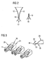
- Fig. 2 shows two cross-sections through the contact region 19 of a contact element 10.
- the left-hand diagram shows a cross-section in the longitudinal direction of the spring arms 12 and the right-hand diagram shows a cross-section perpendicular to the longitudinal direction of the spring arms 12 through the contact region 19.
- the tapering front receiving region 17 can clearly be seen in the left-hand diagram.
- the lower receiving region 18 also has a tapering form, as can be seen in the right-hand diagram.
- the lower receiving region 18 merges in a flowing manner into the front receiving region 17, so a tapering receiving region is also formed in the transition region between the front and the lower receiving region 17, 18.
- the contact element 10 can thus be placed by a placement operation vertically from above onto the solar panel, in which the fixed contact of the solar panel is inserted into the contact region 19 through the lower receiving region 18, and also by a lateral pushing-on operation in which the fixed contact of the solar panel is inserted into the contact region 19 via the front receiving region 17, in an automatic contacting operation.
- any placement direction which is located between a vertical and a lateral placement direction is possible.
- Fig. 3 shows, in a perspective view, three second contact elements 20 which can be inserted into the holding devices 5 of the connecting box 1 instead of the contact elements 10.
- the second contact elements 20 also have spring terminals 11 which are formed in one piece with further contact terminals 21.
- the further contact terminals 21 have a third receiving region 36 arranged opposite the spring terminals 11.
- Fig. 3 shows, on the right-hand side, a cross-section through the further contact terminal 21 of a second contact element 20.
- the further contact terminal 21 comprises a spring contact 32 limiting a second contact region 35 with a second contact board 33.
- a third receiving region 36 tapering in the insertion direction is formed in the direction of the second contact region 35 between the spring contact 32 and the second contact board 33.
- the spring contact 32 is resiliently held and has, preferably in the second contact region 35, a fixed spacing from the fixed second contact board 32.
- the second contact element 20 is also suitable for contacting in an automatic placement operation owing to the tapering third receiving region 36.
- the second contact region 35 is arranged parallel to the base board 2.
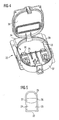
- Fig. 4 shows a second connecting box 22 providing a further embodiment of a connecting box.
- the second connecting box 22 comprises a second base board 25 and a second peripheral side wall 37.
- the other side wall 37 delimits a lid opening 27.
- a second lid 38 is held on the second side wall 37.
- the second base board 25 covers a front region of the second connecting box 22 and extends right up over the centre of the lid opening 27.
- the second base board 25 has a second opening 39 extending up to a back edge region of the sealing face 26.
- the second side wall 37 merges, in a back region, into a housing wall 24 guided up to a back side wall.
- the housing wall 24 delimits a receiving space 23 formed behind the lid opening 27.
- the receiving region 23 is used, during the automatic assembly operation, to receive the fixed contacts of the solar panel and allows a subsequent lateral displacement of the second connecting box 22 with respect to the fixed contacts.
- the fixed contacts of the solar panel located in the receiving space 23 are pushed in the direction of the second contact elements 20 during the lateral displacement.
- the formation of a receiving space 23 is also possible in the embodiment of the connecting box 1 of Fig. 1.
- Fig. 5 shows a view from below of the second connecting box 22.
- the second base board 25, ending in a region located beneath the lid opening 27, is arranged in the front region.
- the receiving space 23 covered by the housing wall 24 is formed in the back region.
- the second connecting box, of which the peripheral sealing face 26 is covered by an adhesive is guided until just over the surface of the solar panel, wherein the fixed contacts of the solar panel are located in the receiving space 23.
- the fixed contacts are then inserted into the contact regions of the contact elements 10 or of the second contact elements 20 by a lateral movement.
- the second connecting box with the sealing face 26 is then placed on the surface of the solar panel. Once the glue has dried, the second connecting box 22 is rigidly connected to the solar panel.
- the second connecting box 22 comprises, on the second base board 25, contact elements 10 or second contact elements 20. In the illustrated embodiment the second connecting box 22 does not have any terminals for electric lines.
- the second connecting box 22 can also have cable openings 6 corresponding to the connecting box of Fig. 1, depending on the embodiment.
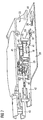
- Fig. 6 shows a cross-section through a third connecting box 40 and a solar panel 28 with fixed contacts 41.
- the solar panel 28 comprises solar cells 44 generating an electrical voltage from sunlight which is tapped by foil lines 29.
- the foil lines 29 are soldered to solder tongues 30.
- the solder tongues 30 are guided to a connection board 53.
- the connection board 53 is fastened to the solar panel 28, preferably glued.
- the connection board 53 comprises pins 45 which are formed on the upper side of the connection board 53 and have a fixed length. Fixed contacts 41 are led out at one contact side in the pins 45.
- the fixed contacts 41 are electrically connected to the solder tongues 30.
- the connection board 53 and the pins 45 are preferably injected from a plastics material.
- the fixed contacts 41 are constructed in the form of contact tongues arranged parallel to the solar panel 28 or parallel to the arrangement of spring contacts 32 and the second contact boards 33 of the second contact elements 20.
- the third connecting box 40 comprises a receiving space 23 formed in front of the second base board 25 and the second contact elements 20. No base board 25 is provided below the receiving space 23.
- the connection board 53 is introduced into the receiving space 23 and then the fixed contacts 41 are inserted into the second contact regions 35 of the second contact elements 20 by a lateral movement of the third connecting box 40.
- the third connecting box 40 is then placed with the peripheral sealing face, covered with adhesive, on the solar panel 28. Automatic contacting and assembling of the solar panel 28 is possible as the solar panel 28 has a connection board 53 with fixed electrical contacts 41 which are contacted by the foil lines 29 which tap the voltage generated by the solar panel 28.
- the third connecting box 40 comprises a contact connector 42 and a contact socket 43 formed on a side wall of the third connecting box 40.
- the contact connector 42 and the contact socket 43 comprise a pin contact 46 which is electrically connected to the second contact element 20 via a second spring terminal 47.
- Fig. 7 shows the third connecting box 40 which, however, in the illustrated embodiment comprises first contact elements 10 instead of the second contact elements 20.
- the first contact elements 10 have, in contrast to the second contact elements 20, receiving regions 17, 18 in the contact regions 19 which are formed substantially perpendicularly to the second base board 25.
- the first contact elements 10 are suitable for contacting fixed contacts 41 of the solar panel 28 using an automated assembling operation, which contacts are arranged perpendicularly to the solar panel 28.
- the solar panel 28 comprises a connection board 53 and pins 45 comprising fixed contacts on one contact side.
- the contacts 41 are arranged perpendicularly to the solar panel 28 and inserted in the contact regions 19 of the contact elements 10.
- the third connecting box 40 is assembled on the solar panel 28.
- the form of the contact elements 10 provides the advantage that the fixed contacts 41 can be contacted by a vertical placement movement of the third connecting box 40.
- the fixed contacts 41 are inserted into the contact region 19 of the contact elements 10 via the lower receiving region 18. Therefore, it is not necessary to provide a receiving space 23 when using contact elements 10.
- Owing to the formation of the front receiving region 17 it is, however, also possible to contact the contact elements 10 via a laterally directed movement of the third connecting box 40 with the fixed contacts 41 of the solar panel 28, the fixed contacts 41 being inserted into the contact region 19 of the contact elements 10 via the front receiving region 17.
- directions of movement during assembly are also possible which comprise a combination of a vertical and a lateral movement operation.
- a movement of the third connecting box 40, for example at an angle of 45° to the solar panel 28, can also be advantageous in automatic assembling and contacting, depending on the position of the solar panel, the construction of the connection board 53 and the pins 46 and the embodiment of the receiving space 23.
- Fig. 8 shows a fourth connecting box 48 and a solar panel 28.
- Solar cells 44 which generate an electric voltage from sunlight and convey it via two foil conductors 29, are arranged on the solar panel 28.
- the foil conductors 29 are soldered to contact tongues 30 guided to the connection board 53.
- the connection board 53 is fastened to the upper side of the solar panel 28.
- the connection board 53 comprises two pins 45 which have contacts 41 fixed to one contact side.
- the fixed contacts 41 are electrically connected to the solder tongues 30.
- the fourth connecting box 48 comprises a base panel in which an opening 4 for feeding the contacts 41 is formed.
- the fourth connecting box 48 comprises a peripheral side wall 3 delimiting a lid opening.
- a fourth lid 49 for closing the fourth connecting box 48 is also provided. Cable openings 6 are introduced into the side wall 3.
- the fourth connecting box 48 is also suitable for an automatic assembling operation. However, in this embodiment the electrical contact between the fixed contacts 41 and the conductors of the cable 50 has to be carried out by manual contacting.
- the fourth connecting box 48 is preferably securely glued via a peripheral sealing face to the solar panel.
- a contact and holding device 54 comprising two contact and holding arms which are each electrically connected to one of the two fixed contacts 41, is preferably provided on the connection board 53.
- the contact and holding arms are preferably constructed in the form of insulation piercing connecting devices.
- the insulation piercing connecting devices are used for holding and contacting a diode with the two fixed contacts 41.
Landscapes
- Photovoltaic Devices (AREA)
Abstract
Description
Claims (12)
- Connecting box (1, 22, 40) for a solar panel (28) comprising a housing (2, 3, 16, 25, 24, 37, 38, 49) comprising contact elements (10, 20) for electrically connecting to contacts (41) of the solar panel (28), the housing (2, 3, 16, 25, 24, 37, 38, 49) comprising an opening for introducing the contacts (41) of the solar panel (28), characterised in that the contact elements (10, 20) comprise a tapered receiving region (17, 18, 36) to which a contact region (19, 35) adjoins, so automatic introduction of a contact (41) of the solar panel (28) via the receiving region (17, 18, 36) into the contact region (19, 35) of the contact elements (10, 20) is possible.
- Connecting box according to claim 1, characterised in that the contact element (10, 20) comprises two spring contacts (12, 32, 33), in that the two spring contacts (12, 32, 33) have a spacing in the contact region (19, 35) which is smaller than the width of a contact to be contacted.
- Connecting box according to either claim 1 or claim 2, characterised in that the receiving region (17, 18) extends over an angular range of up to 90°.
- Connecting box according to any one of claims 1 to 3, characterised in that a base board (2, 25) comprises a larger opening (4, 39) in the longitudinal direction of the contact elements than is necessary for receiving contacts (41), in that, in the region of the opening (4, 39), the housing comprises a receiving space (23) for insertion of the contact (41), in that the receiving space (23) is laterally offset with respect to a lid opening (27).
- Connecting box according to any one of claims 1 to 4, characterised in that the connecting box (1, 22, 40) comprises a flat, peripheral sealing face (26) on the lower side for gluing the connecting box (1, 22, 40) to the solar panel (28).
- Connecting box according to either claim 4 or claim 5, characterised in that, in the region of the receiving space (23), in the cross-section perpendicular to the base board, the housing has a partially rectangular shape.
- Solar panel comprising a solar cell (44), comprising electric lines (29) for conveying the voltage generated by the solar cell (44), characterised in that a connecting element (53) is fastened to the solar panel (28), in that the connecting element (53) comprises fixed contacts (41), and in that the fixed contacts (41) are connected to the lines (29) of the solar cell (44).
- Solar panel of claim 7, characterised in that the connecting element (53) comprises at least one contact holder (45), in that a fixed contact (41) is held in the contact holder (45).
- Solar panel according to either claim 7 or claim 8, characterised in that the connecting element (53) comprises a board on which the fixed contact (41) and the contact holder (45) are fastened, and in that the board is fastened to the solar panel (28) by a glued joint.
- Solar panel according to either claim 8 or claim 9, characterised in that the connecting element (53) comprises at least one contact tongue (30) which is electrically connected to the fixed contact (41) and to the electric line (29) of the solar cell (44).
- Solar panel according to any one of claims 7 to 10, characterised in that the connecting element (53) comprises a contact and holding device with two contact and holding arms (54), in that a respective contact and holding arm (54) is electrically connected to a fixed contact (41), and in that the contact and holding device is used to securely fix an electrical component, in particular a diode.
- Solar panel according to claim 7, comprising a connecting box according to claim 1.
Applications Claiming Priority (2)
| Application Number | Priority Date | Filing Date | Title |
|---|---|---|---|
| DE20311183U | 2003-07-21 | ||
| DE20311183U DE20311183U1 (en) | 2003-07-21 | 2003-07-21 | Junction box for a solar panel and solar panel |
Publications (4)
| Publication Number | Publication Date |
|---|---|
| EP1501157A2 true EP1501157A2 (en) | 2005-01-26 |
| EP1501157A3 EP1501157A3 (en) | 2007-03-14 |
| EP1501157B1 EP1501157B1 (en) | 2009-04-15 |
| EP1501157B2 EP1501157B2 (en) | 2016-04-20 |
Family
ID=32695308
Family Applications (1)
| Application Number | Title | Priority Date | Filing Date |
|---|---|---|---|
| EP04015561.6A Expired - Lifetime EP1501157B2 (en) | 2003-07-21 | 2004-07-02 | Connecting box for a solar panel and solar panel |
Country Status (7)
| Country | Link |
|---|---|
| US (1) | US7097516B2 (en) |
| EP (1) | EP1501157B2 (en) |
| JP (1) | JP2005045256A (en) |
| CN (1) | CN100409488C (en) |
| AT (1) | ATE429047T1 (en) |
| DE (2) | DE20311183U1 (en) |
| ES (1) | ES2323422T5 (en) |
Cited By (6)
| Publication number | Priority date | Publication date | Assignee | Title |
|---|---|---|---|---|
| EP1727240A1 (en) | 2005-05-25 | 2006-11-29 | Günther Spelsberg GmbH & Co. KG | Electrical terminal box |
| EP1729348A2 (en) | 2005-06-03 | 2006-12-06 | Günther Spelsberg GmbH & Co. KG | Junction box for a solar cell modul |
| EP2058867A2 (en) | 2007-11-12 | 2009-05-13 | Multi-Holding AG | Junction box for a photovoltaic solar panel |
| WO2009074335A1 (en) | 2007-12-13 | 2009-06-18 | Yamaichi Electronics Deutschland Gmbh | Junction box, system, method, and use |
| WO2010042166A3 (en) * | 2008-10-10 | 2010-09-10 | Tyco Electronics Corporation | Connecting box for a solar panel |
| US20110220187A1 (en) * | 2010-03-15 | 2011-09-15 | Feng Wang | Junction Module for A Building Integrated Photovoltaic System |
Families Citing this family (157)
| Publication number | Priority date | Publication date | Assignee | Title |
|---|---|---|---|---|
| DE102004025627A1 (en) * | 2004-05-25 | 2005-12-22 | Tyco Electronics Amp Gmbh | Solar module with connection element |
| US7628659B2 (en) * | 2004-06-28 | 2009-12-08 | Dt Search & Designs Llc | Enhanced cable for field data distribution system |
| US7238063B2 (en) * | 2004-06-28 | 2007-07-03 | Alvin Dean Thompson | Field communication and computer data distribution system |
| EP1836735B1 (en) * | 2005-01-14 | 2010-10-20 | Multi-Holding AG | Connection box for a solar panel |
| DE102005025632B4 (en) * | 2005-06-03 | 2015-09-17 | Te Connectivity Germany Gmbh | Connecting device for connecting electrical foil conductors |
| JP4741928B2 (en) * | 2005-10-20 | 2011-08-10 | 行田電線株式会社 | Terminal box for solar cell module |
| US11881814B2 (en) | 2005-12-05 | 2024-01-23 | Solaredge Technologies Ltd. | Testing of a photovoltaic panel |
| US10693415B2 (en) | 2007-12-05 | 2020-06-23 | Solaredge Technologies Ltd. | Testing of a photovoltaic panel |
| JP5252316B2 (en) * | 2006-04-13 | 2013-07-31 | ワイドミュラー インターフェース ゲゼルシャフト ミット ベシュレンクテル ハフツング ウント コンパニー コマンディートゲゼルシャフト | Electrical connection device for flat conductors |
| WO2007136569A2 (en) * | 2006-05-15 | 2007-11-29 | Antaya Technologies Corporation | Electrical connector assembly |
| EP2038976A1 (en) * | 2006-06-29 | 2009-03-25 | Huber & Suhner Ag | Connection box |
| US7291036B1 (en) * | 2006-11-08 | 2007-11-06 | Tyco Electronics Corporation | Photovoltaic connection system |
| US20080110490A1 (en) * | 2006-11-15 | 2008-05-15 | Tyco Electronics Corporation | Photovoltaic connection system |
| JP2010510686A (en) * | 2006-11-21 | 2010-04-02 | ビーピー・コーポレーション・ノース・アメリカ・インコーポレーテッド | Cable connector for solar cell module and installation method thereof |
| US20080115911A1 (en) * | 2006-11-22 | 2008-05-22 | Tyco Electronics Corporation | Heat dissipation system for solarlok photovoltaic interconnection system |
| US8618692B2 (en) | 2007-12-04 | 2013-12-31 | Solaredge Technologies Ltd. | Distributed power system using direct current power sources |
| US11309832B2 (en) | 2006-12-06 | 2022-04-19 | Solaredge Technologies Ltd. | Distributed power harvesting systems using DC power sources |
| US8384243B2 (en) | 2007-12-04 | 2013-02-26 | Solaredge Technologies Ltd. | Distributed power harvesting systems using DC power sources |
| US8816535B2 (en) | 2007-10-10 | 2014-08-26 | Solaredge Technologies, Ltd. | System and method for protection during inverter shutdown in distributed power installations |
| US11687112B2 (en) | 2006-12-06 | 2023-06-27 | Solaredge Technologies Ltd. | Distributed power harvesting systems using DC power sources |
| US11888387B2 (en) | 2006-12-06 | 2024-01-30 | Solaredge Technologies Ltd. | Safety mechanisms, wake up and shutdown methods in distributed power installations |
| US12316274B2 (en) | 2006-12-06 | 2025-05-27 | Solaredge Technologies Ltd. | Pairing of components in a direct current distributed power generation system |
| US8963369B2 (en) | 2007-12-04 | 2015-02-24 | Solaredge Technologies Ltd. | Distributed power harvesting systems using DC power sources |
| US9088178B2 (en) | 2006-12-06 | 2015-07-21 | Solaredge Technologies Ltd | Distributed power harvesting systems using DC power sources |
| US8473250B2 (en) | 2006-12-06 | 2013-06-25 | Solaredge, Ltd. | Monitoring of distributed power harvesting systems using DC power sources |
| US11855231B2 (en) | 2006-12-06 | 2023-12-26 | Solaredge Technologies Ltd. | Distributed power harvesting systems using DC power sources |
| US8013472B2 (en) | 2006-12-06 | 2011-09-06 | Solaredge, Ltd. | Method for distributed power harvesting using DC power sources |
| US11296650B2 (en) | 2006-12-06 | 2022-04-05 | Solaredge Technologies Ltd. | System and method for protection during inverter shutdown in distributed power installations |
| US8947194B2 (en) | 2009-05-26 | 2015-02-03 | Solaredge Technologies Ltd. | Theft detection and prevention in a power generation system |
| US11735910B2 (en) | 2006-12-06 | 2023-08-22 | Solaredge Technologies Ltd. | Distributed power system using direct current power sources |
| US11569659B2 (en) | 2006-12-06 | 2023-01-31 | Solaredge Technologies Ltd. | Distributed power harvesting systems using DC power sources |
| US9112379B2 (en) | 2006-12-06 | 2015-08-18 | Solaredge Technologies Ltd. | Pairing of components in a direct current distributed power generation system |
| US8319483B2 (en) | 2007-08-06 | 2012-11-27 | Solaredge Technologies Ltd. | Digital average input current control in power converter |
| US8319471B2 (en) | 2006-12-06 | 2012-11-27 | Solaredge, Ltd. | Battery power delivery module |
| US9130401B2 (en) | 2006-12-06 | 2015-09-08 | Solaredge Technologies Ltd. | Distributed power harvesting systems using DC power sources |
| US8531055B2 (en) | 2006-12-06 | 2013-09-10 | Solaredge Ltd. | Safety mechanisms, wake up and shutdown methods in distributed power installations |
| US7387537B1 (en) * | 2007-01-03 | 2008-06-17 | Tyco Electronics Corporation | Connector system for solar cell roofing tiles |
| DE102007006433A1 (en) * | 2007-02-05 | 2008-08-07 | Phoenix Contact Gmbh & Co. Kg | Connection box for electrically connecting solar module, has clamp spring passing from one position into another position during attachment of housing upper part on housing lower part, so that connection line is automatically contactable |
| WO2008095668A1 (en) * | 2007-02-05 | 2008-08-14 | Phoenix Contact Gmbh & Co. Kg | Junction box and connecting box for a solar module |
| CN101606294B (en) * | 2007-02-05 | 2013-01-02 | 菲尼克斯电气公司 | Junction box and connecting box for a solar module |
| US7762832B2 (en) | 2007-02-12 | 2010-07-27 | Minnick Jamie J | Systems for providing electrical interconnection between solar modules |
| EP1976026A3 (en) * | 2007-03-28 | 2009-09-09 | Günther Spelsberg GmbH & Co. KG | Junction box |
| DE202007005126U1 (en) | 2007-04-04 | 2008-08-14 | Weidmüller Interface GmbH & Co. KG | Electrical connection device for contacts, in particular blade contacts |
| US7614919B2 (en) * | 2007-05-09 | 2009-11-10 | Tyco Electronics Corporation | Bussing connector |
| US20080283118A1 (en) * | 2007-05-17 | 2008-11-20 | Larankelo, Inc. | Photovoltaic ac inverter mount and interconnect |
| DE102007023210B3 (en) * | 2007-05-18 | 2008-09-18 | Anton Gensler Gmbh | Electrical connection device for photovoltaic modules |
| DE102007032603A1 (en) | 2007-07-11 | 2009-01-15 | Weidmüller Interface GmbH & Co. KG | Terminal contact and method for laminating objects provided with electrical connection contacts |
| DE102007043178A1 (en) * | 2007-09-11 | 2009-03-12 | Yamaichi Electronics Deutschland Gmbh | Junction box, solar panel, contact device and procedure |
| US20090084426A1 (en) * | 2007-09-28 | 2009-04-02 | Enphase Energy, Inc. | Universal interface for a photovoltaic module |
| US8222533B2 (en) * | 2007-10-02 | 2012-07-17 | Tyco Electronics Corporation | Low profile photovoltaic (LPPV) box |
| US7625238B2 (en) * | 2007-10-31 | 2009-12-01 | Tyco Electronics Corporation | Low profile photovoltaic edge connector |
| US9291696B2 (en) | 2007-12-05 | 2016-03-22 | Solaredge Technologies Ltd. | Photovoltaic system power tracking method |
| WO2009072077A1 (en) | 2007-12-05 | 2009-06-11 | Meir Adest | Testing of a photovoltaic panel |
| US11264947B2 (en) | 2007-12-05 | 2022-03-01 | Solaredge Technologies Ltd. | Testing of a photovoltaic panel |
| US8049523B2 (en) | 2007-12-05 | 2011-11-01 | Solaredge Technologies Ltd. | Current sensing on a MOSFET |
| WO2009073867A1 (en) | 2007-12-05 | 2009-06-11 | Solaredge, Ltd. | Parallel connected inverters |
| US7641522B2 (en) * | 2007-12-11 | 2010-01-05 | Lasen Development Llc | Electrical-connection device, particularly for photovoltaic-cell solar panels |
| DE102008003448B4 (en) | 2008-01-08 | 2017-01-05 | Yamaichi Electronics Deutschland Gmbh | Junction box, use, solar panel, contact element, and procedure |
| DE102008022297B4 (en) * | 2008-03-13 | 2011-04-14 | Fpe Fischer Gmbh | Connection box for solar modules and method for mounting them on the modules |
| EP2272161B1 (en) | 2008-03-24 | 2014-06-25 | Solaredge Technologies Ltd. | Switch mode converter including auxiliary commutation circuit for zero current switching |
| JP2009246039A (en) * | 2008-03-28 | 2009-10-22 | Mitsubishi Electric Corp | Terminal box device for use in solar battery module |
| EP2279529A2 (en) * | 2008-04-16 | 2011-02-02 | Molex Incorporated | Solar panel junction box |
| DE102008022055B4 (en) * | 2008-05-03 | 2010-01-21 | Lumberg Connect Gmbh | Junction box for a solar module |
| DE102008022049B4 (en) * | 2008-05-03 | 2010-07-15 | Lumberg Connect Gmbh | Connection box for connecting a solar module |
| DE102008022050B3 (en) * | 2008-05-03 | 2009-02-26 | Lumberg Connect Gmbh | Connection box for solar module, has base part with two holders, where one holder for contacting section of supply cable maintains contacting section in parallel plane at position displaced by angle, and holders form bracket cross |
| EP2294669B8 (en) | 2008-05-05 | 2016-12-07 | Solaredge Technologies Ltd. | Direct current power combiner |
| DE102008022908B4 (en) * | 2008-05-09 | 2014-11-27 | Yamaichi Electronics Deutschland Gmbh | Junction box, uses a junction box and procedures |
| DE102008028462A1 (en) * | 2008-06-14 | 2009-12-17 | Kostal Industrie Elektrik Gmbh | Electrical connection and connection box for a solar cell module |
| CN201260137Y (en) * | 2008-07-18 | 2009-06-17 | 泰科电子(上海)有限公司 | Photovoltaic integrated wiring box for building |
| US7591690B1 (en) | 2008-08-07 | 2009-09-22 | Hong Tai Electric Industrial Co., Ltd. | Connecting device for solar panel |
| DE202008011245U1 (en) | 2008-08-22 | 2008-10-16 | HONG TAI ELECTRIC INDUSTRIAL CO., LTD., Lujhu | Improved connection of solar power plate |
| DE202009004930U1 (en) | 2008-09-22 | 2010-03-04 | Weidmüller Interface GmbH & Co. KG | Electrical connection device for flat conductors |
| DE102008048443A1 (en) * | 2008-09-23 | 2010-04-08 | Tyco Electronics Amp Gmbh | Connecting device for connecting an electrical conductor to a solar module assembly and solar module assembly with such a connection device |
| DE102008052348B4 (en) * | 2008-10-20 | 2016-12-29 | Te Connectivity Germany Gmbh | Connecting device for connecting an electrical conductor with a solar module, and solar module with such a connection device |
| DE102008061268B4 (en) * | 2008-12-10 | 2017-02-23 | Phoenix Contact Gmbh & Co. Kg | Contact terminal and connector with contact terminal |
| DE102008062034B4 (en) * | 2008-12-12 | 2010-08-12 | Tyco Electronics Amp Gmbh | Connecting device for connection to a solar module and solar module with such a connection device |
| DE102009004100A1 (en) * | 2009-01-08 | 2010-07-15 | Yamaichi Electronics Deutschland Gmbh | Solar panel for generating electrical energy from sunlight, has electrical conductors sectionally arranged in recess and electrically connected by diode, and cover element fixed at connection side element and covering recess and diode |
| US8435056B2 (en) * | 2009-04-16 | 2013-05-07 | Enphase Energy, Inc. | Apparatus for coupling power generated by a photovoltaic module to an output |
| KR101024619B1 (en) * | 2009-04-24 | 2011-03-25 | 커넥스일렉트로닉스(주) | Smart Junction Box for Solar Module |
| US8303349B2 (en) * | 2009-05-22 | 2012-11-06 | Solaredge Technologies Ltd. | Dual compressive connector |
| CN102422429B (en) | 2009-05-22 | 2014-08-06 | 太阳能安吉科技有限公司 | Electrically isolated heat dissipating junction box |
| US8690110B2 (en) | 2009-05-25 | 2014-04-08 | Solaredge Technologies Ltd. | Bracket for connection of a junction box to photovoltaic panels |
| US7862383B2 (en) * | 2009-06-03 | 2011-01-04 | Tyco Electronics Corporation | Electrical connector for a solar module assembly |
| JP2011018463A (en) * | 2009-07-07 | 2011-01-27 | Kitani Denki Kk | Fastening connection fixing structure of cable in photovoltaic power generation system |
| JP5063657B2 (en) * | 2009-10-07 | 2012-10-31 | 日本航空電子工業株式会社 | Contact and connection device having the same |
| US12418177B2 (en) | 2009-10-24 | 2025-09-16 | Solaredge Technologies Ltd. | Distributed power system using direct current power sources |
| US8710699B2 (en) | 2009-12-01 | 2014-04-29 | Solaredge Technologies Ltd. | Dual use photovoltaic system |
| DE102009058118A1 (en) * | 2009-12-12 | 2011-06-16 | Lumberg Connect Gmbh | Junction box for solar modules |
| US8766696B2 (en) | 2010-01-27 | 2014-07-01 | Solaredge Technologies Ltd. | Fast voltage level shifter circuit |
| DE102010007093A1 (en) * | 2010-02-06 | 2011-08-11 | KOSTAL Industrie Elektrik GmbH, 58507 | Electrical device with a passage of a cable through a housing wall |
| DE102010002565B8 (en) * | 2010-03-04 | 2012-03-22 | Tyco Electronics Amp Gmbh | Connecting device for a solar module |
| CN102208783B (en) * | 2010-03-31 | 2014-04-02 | 富士康(昆山)电脑接插件有限公司 | Junction box |
| DE102010029714A1 (en) * | 2010-04-08 | 2011-10-13 | Tyco Electronics Amp Gmbh | Electrical spring clamp, punched grid, busbar and electrical connection device |
| US8113890B2 (en) * | 2010-05-04 | 2012-02-14 | Tyco Electronics Corporation | Solar module connector and method of use |
| CN102906884B (en) * | 2010-05-20 | 2015-09-02 | 行田电线株式会社 | Solar module terminal box |
| CN201754409U (en) * | 2010-06-30 | 2011-03-02 | 比亚迪股份有限公司 | Solar battery terminal box |
| CN101976970B (en) * | 2010-07-30 | 2012-10-10 | 苏州固锝新能源科技有限公司 | Photovoltaic assembly junction box |
| US20120033392A1 (en) * | 2010-08-09 | 2012-02-09 | Tyco Electronics Corporation | Modular Junction Box for a Photovoltaic Module |
| US8723031B2 (en) * | 2010-08-30 | 2014-05-13 | Hosiden Corporation | Terminal box |
| US8388358B2 (en) * | 2010-09-28 | 2013-03-05 | Tyco Electronics Corporation | Contact rail for a junction box |
| CA2752914C (en) * | 2010-09-29 | 2019-06-04 | Hosiden Corporation | Terminal box, output cable connection arrangement for solar cell module terminal box and fixation arrangement for the output cable |
| US8471144B2 (en) * | 2010-10-06 | 2013-06-25 | Solarworld Ag | Adapter box for protection of the electrical connection of a photovoltaic module |
| US10673229B2 (en) | 2010-11-09 | 2020-06-02 | Solaredge Technologies Ltd. | Arc detection and prevention in a power generation system |
| GB2485527B (en) | 2010-11-09 | 2012-12-19 | Solaredge Technologies Ltd | Arc detection and prevention in a power generation system |
| US10673222B2 (en) | 2010-11-09 | 2020-06-02 | Solaredge Technologies Ltd. | Arc detection and prevention in a power generation system |
| US10230310B2 (en) | 2016-04-05 | 2019-03-12 | Solaredge Technologies Ltd | Safety switch for photovoltaic systems |
| GB2486408A (en) | 2010-12-09 | 2012-06-20 | Solaredge Technologies Ltd | Disconnection of a string carrying direct current |
| WO2012083049A1 (en) | 2010-12-17 | 2012-06-21 | First Solar, Inc | Electrical connection system |
| GB2483317B (en) | 2011-01-12 | 2012-08-22 | Solaredge Technologies Ltd | Serially connected inverters |
| DE102011009717A1 (en) * | 2011-01-29 | 2012-08-02 | Kostal Industrie Elektrik Gmbh | Electrical connection and junction box for a solar cell module and method for establishing an electrical connection |
| DE102011005282A1 (en) * | 2011-03-09 | 2012-09-13 | Robert Bosch Gmbh | Junction box and solar cell arrangement |
| CN102738276B (en) * | 2011-04-14 | 2015-08-05 | 乐清市信达利实业有限公司 | Terminal box |
| GB2490499A (en) * | 2011-05-03 | 2012-11-07 | Solaredge Technologies Ltd | Junction box assembly for electrical connections to photovoltaic panels |
| US8748743B2 (en) * | 2011-07-05 | 2014-06-10 | Hon Hai Precision Industry Co., Ltd. | Junction box improved locking portion |
| TWM422759U (en) * | 2011-07-11 | 2012-02-11 | Ampower Technology Co Ltd | Cooling structure for junction box |
| EP2735021A4 (en) | 2011-07-18 | 2015-03-11 | Enphase Energy Inc | ELASTIC ASSEMBLY ASSEMBLY FOR PHOTOVOLTAIC MODULES |
| CN202259353U (en) * | 2011-08-15 | 2012-05-30 | 泰科电子(上海)有限公司 | Junction box |
| US8570005B2 (en) | 2011-09-12 | 2013-10-29 | Solaredge Technologies Ltd. | Direct current link circuit |
| CA2849766A1 (en) | 2011-09-23 | 2013-03-28 | Dt Search & Designs Llc | Stackable cable reel with field data distribution system |
| US8829343B1 (en) | 2011-09-26 | 2014-09-09 | Dt Search And Designs, Llc | Cable connector seal kit with torque limiting spacers |
| US9728664B2 (en) | 2011-09-30 | 2017-08-08 | Saint-Gobain Glass France | Solar module with connection socket, and method for producing the same |
| CN102306672B (en) * | 2011-09-30 | 2013-04-17 | 苏州固锝新能源科技有限公司 | Modular junction box |
| JP5729648B2 (en) * | 2011-10-13 | 2015-06-03 | ホシデン株式会社 | Terminal box for solar cell module |
| CN103187646B (en) * | 2011-12-28 | 2015-05-27 | 富泰华工业(深圳)有限公司 | Power supply bolt structure |
| GB2498365A (en) | 2012-01-11 | 2013-07-17 | Solaredge Technologies Ltd | Photovoltaic module |
| US9853565B2 (en) | 2012-01-30 | 2017-12-26 | Solaredge Technologies Ltd. | Maximized power in a photovoltaic distributed power system |
| GB2498791A (en) | 2012-01-30 | 2013-07-31 | Solaredge Technologies Ltd | Photovoltaic panel circuitry |
| GB2498790A (en) | 2012-01-30 | 2013-07-31 | Solaredge Technologies Ltd | Maximising power in a photovoltaic distributed power system |
| GB2499991A (en) | 2012-03-05 | 2013-09-11 | Solaredge Technologies Ltd | DC link circuit for photovoltaic array |
| CN104488159B (en) | 2012-05-25 | 2018-03-23 | 太阳能安吉科技有限公司 | Circuits for interconnected DC power supplies |
| US10115841B2 (en) | 2012-06-04 | 2018-10-30 | Solaredge Technologies Ltd. | Integrated photovoltaic panel circuitry |
| US20140120786A1 (en) | 2012-11-01 | 2014-05-01 | Avx Corporation | Single element wire to board connector |
| US8721376B1 (en) * | 2012-11-01 | 2014-05-13 | Avx Corporation | Single element wire to board connector |
| USD734653S1 (en) | 2012-11-09 | 2015-07-21 | Enphase Energy, Inc. | AC module mounting bracket |
| US9941813B2 (en) | 2013-03-14 | 2018-04-10 | Solaredge Technologies Ltd. | High frequency multi-level inverter |
| US9548619B2 (en) | 2013-03-14 | 2017-01-17 | Solaredge Technologies Ltd. | Method and apparatus for storing and depleting energy |
| EP2779251B1 (en) | 2013-03-15 | 2019-02-27 | Solaredge Technologies Ltd. | Bypass mechanism |
| CN103326184B (en) * | 2013-06-19 | 2015-12-02 | 欧姆龙(上海)有限公司 | Can the lid of closed/open relative to the main body of electronic equipment |
| EP3087672B1 (en) * | 2013-12-23 | 2020-02-12 | TE Connectivity India Private Limited | Housing for solar panel electric connection |
| EP3087671A1 (en) * | 2013-12-23 | 2016-11-02 | TE Connectivity India Private Limited | Housing for solar panel electric connection |
| US9196973B2 (en) * | 2014-03-06 | 2015-11-24 | Chicony Power Technology Co., Ltd. | Solar junction box and wire connecting structure thereof |
| US9318974B2 (en) | 2014-03-26 | 2016-04-19 | Solaredge Technologies Ltd. | Multi-level inverter with flying capacitor topology |
| TWI511394B (en) * | 2014-06-10 | 2015-12-01 | Tarn Yu Entpr Co Ltd | Activation of electrical connectors |
| US9391386B2 (en) | 2014-10-06 | 2016-07-12 | Avx Corporation | Caged poke home contact |
| US9496697B1 (en) | 2015-10-16 | 2016-11-15 | Imagineering Plus Plus Llc | Roof top junction box |
| US11177663B2 (en) | 2016-04-05 | 2021-11-16 | Solaredge Technologies Ltd. | Chain of power devices |
| US11018623B2 (en) | 2016-04-05 | 2021-05-25 | Solaredge Technologies Ltd. | Safety switch for photovoltaic systems |
| US12057807B2 (en) | 2016-04-05 | 2024-08-06 | Solaredge Technologies Ltd. | Chain of power devices |
| DE102017104782A1 (en) * | 2017-03-07 | 2018-09-13 | Sma Solar Technology Ag | Solar module, connection system and solar module system |
| US10320096B2 (en) | 2017-06-01 | 2019-06-11 | Avx Corporation | Flexing poke home contact |
| CN207977486U (en) * | 2018-01-23 | 2018-10-16 | 泰科电子(上海)有限公司 | Conducting terminal and connector assembly |
| US11515693B2 (en) | 2018-04-26 | 2022-11-29 | Easy Solar Products, Llc | Groove indicated junction box |
| JP2020161233A (en) * | 2019-03-25 | 2020-10-01 | 矢崎総業株式会社 | connector |
| KR102471357B1 (en) | 2020-07-31 | 2022-11-25 | 신선숙 | Easy interl ocking solar junction box for easy connection of solar module's busbar |
| US11205918B1 (en) * | 2021-04-27 | 2021-12-21 | Walter Corporation LLC | Apparatus and method for battery charging and power generation |
| KR102827865B1 (en) | 2021-11-23 | 2025-07-01 | 신선숙 | Junction box for high-efficiency ultra-small bifacial photovoltaic module |
| US11848548B1 (en) * | 2023-02-27 | 2023-12-19 | Sunrun Inc. | Enclosure assembly with housing |
Family Cites Families (21)
| Publication number | Priority date | Publication date | Assignee | Title |
|---|---|---|---|---|
| US2290303A (en) † | 1940-07-19 | 1942-07-21 | Stop Motion Devices Corp | Electric stop mechanism for knitting machines |
| US4310211A (en) * | 1979-12-26 | 1982-01-12 | Amp Incorporated | High current contact system for solar modules |
| US4283106A (en) * | 1980-02-01 | 1981-08-11 | Amp Incorporated | Symmetrical connector for solar panel arrays |
| DE3136603C2 (en) † | 1981-09-15 | 1983-11-17 | Vaudeha-Elektro GmbH, 5880 Lüdenscheid | Electrical connector |
| US4460232A (en) * | 1982-05-24 | 1984-07-17 | Amp, Incorporated | Junction box for solar modules |
| JPH0454149U (en) * | 1990-09-17 | 1992-05-08 | ||
| EP0521189A1 (en) * | 1991-07-05 | 1993-01-07 | Siemens Solar GmbH | Electrical terminal for a solar module |
| US5513075A (en) * | 1992-05-08 | 1996-04-30 | The Whitaker Corporation | Module for electrically connecting conductor wires to circuits of flat surfaces such as solar panels |
| DE19535960C2 (en) * | 1995-09-27 | 1997-07-17 | Siemens Ag | Contact spring with contact opening |
| JP3012183B2 (en) † | 1995-12-08 | 2000-02-21 | 日本アンテナ株式会社 | Coaxial connector with built-in termination |
| DE19610958C2 (en) * | 1996-03-20 | 1999-02-04 | Weidmueller Interface | Multipole connector with spring-cage connections |
| AU5046398A (en) * | 1996-11-30 | 1998-06-29 | Atlantis Solar Systeme Ag | Clamping device for connecting electrical connections of solar elements |
| JP3459754B2 (en) * | 1997-06-24 | 2003-10-27 | キヤノン株式会社 | Terminal box for solar cell module, method of connecting the same, and solar cell module |
| JP3624720B2 (en) * | 1998-10-29 | 2005-03-02 | 住友電装株式会社 | Terminal box device for solar cell module |
| WO2000030216A1 (en) * | 1998-11-17 | 2000-05-25 | Utilux Pty. Limited | Solar panel cable connector |
| DE19910532B4 (en) † | 1998-12-04 | 2007-05-31 | Scheuten Solar Technology Gmbh | Photovoltaic solar module in plate form |
| US6582249B1 (en) * | 1999-11-17 | 2003-06-24 | Tyco Electronics Amp Gmbh | Apparatus for contacting foil conductors, in particular of a solar module |
| EP1102354B1 (en) * | 1999-11-17 | 2008-05-28 | Tyco Electronics AMP GmbH | Apparatus for contacting foil conductors, in particular of a solar module |
| ATE556184T1 (en) † | 2000-03-28 | 2012-05-15 | Kaneka Corp | SOLAR CELL MODULE AND ROOF EQUIPPED WITH GENERATOR FUNCTION FOR USE THEREOF |
| JP3744458B2 (en) * | 2002-04-10 | 2006-02-08 | 住友電装株式会社 | Terminal box device for solar cell module |
| CN2534693Y (en) * | 2002-04-18 | 2003-02-05 | 上海太阳能科技有限公司 | Electric connector for solar cell assembly |
-
2003
- 2003-07-21 DE DE20311183U patent/DE20311183U1/en not_active Expired - Lifetime
-
2004
- 2004-07-02 DE DE602004020553T patent/DE602004020553D1/en not_active Expired - Lifetime
- 2004-07-02 EP EP04015561.6A patent/EP1501157B2/en not_active Expired - Lifetime
- 2004-07-02 ES ES04015561.6T patent/ES2323422T5/en not_active Expired - Lifetime
- 2004-07-02 AT AT04015561T patent/ATE429047T1/en not_active IP Right Cessation
- 2004-07-21 JP JP2004212907A patent/JP2005045256A/en active Pending
- 2004-07-21 US US10/895,609 patent/US7097516B2/en not_active Expired - Lifetime
- 2004-07-21 CN CNB2004100549049A patent/CN100409488C/en not_active Expired - Lifetime
Cited By (15)
| Publication number | Priority date | Publication date | Assignee | Title |
|---|---|---|---|---|
| EP1727240A1 (en) | 2005-05-25 | 2006-11-29 | Günther Spelsberg GmbH & Co. KG | Electrical terminal box |
| EP1729348A2 (en) | 2005-06-03 | 2006-12-06 | Günther Spelsberg GmbH & Co. KG | Junction box for a solar cell modul |
| EP1729348A3 (en) * | 2005-06-03 | 2008-12-31 | Günther Spelsberg GmbH & Co. KG | Junction box for a solar cell modul |
| EP2058867A3 (en) * | 2007-11-12 | 2009-07-22 | Multi-Holding AG | Junction box for a photovoltaic solar panel |
| WO2009062326A3 (en) * | 2007-11-12 | 2009-07-09 | Applied Materials Inc | Junction box for a photovoltaic solar panel |
| EP2058867A2 (en) | 2007-11-12 | 2009-05-13 | Multi-Holding AG | Junction box for a photovoltaic solar panel |
| US8500462B2 (en) | 2007-11-12 | 2013-08-06 | Applied Materials, Inc. | Junction box for a photovoltaic solar panel |
| EP2637218A1 (en) | 2007-11-12 | 2013-09-11 | Applied Materials, Inc. | Solder element for a junction box and method for producing a solder element |
| EP2637219A2 (en) | 2007-11-12 | 2013-09-11 | Applied Materials, Inc. | Junction box for a photovoltaic solar panel |
| EP2637219A3 (en) * | 2007-11-12 | 2014-01-15 | Applied Materials, Inc. | Junction box for a photovoltaic solar panel |
| US9059350B2 (en) | 2007-11-12 | 2015-06-16 | Applied Materials, Inc. | Junction box for a photovoltaic solar panel |
| WO2009074335A1 (en) | 2007-12-13 | 2009-06-18 | Yamaichi Electronics Deutschland Gmbh | Junction box, system, method, and use |
| WO2010042166A3 (en) * | 2008-10-10 | 2010-09-10 | Tyco Electronics Corporation | Connecting box for a solar panel |
| US7914298B2 (en) | 2008-10-10 | 2011-03-29 | Tyco Electronics Corporation | Solar box and two position solar connectors |
| US20110220187A1 (en) * | 2010-03-15 | 2011-09-15 | Feng Wang | Junction Module for A Building Integrated Photovoltaic System |
Also Published As
| Publication number | Publication date |
|---|---|
| EP1501157A3 (en) | 2007-03-14 |
| EP1501157B2 (en) | 2016-04-20 |
| DE602004020553D1 (en) | 2009-05-28 |
| ES2323422T5 (en) | 2016-09-05 |
| US20050054244A1 (en) | 2005-03-10 |
| JP2005045256A (en) | 2005-02-17 |
| CN1577980A (en) | 2005-02-09 |
| DE20311183U1 (en) | 2004-07-08 |
| ATE429047T1 (en) | 2009-05-15 |
| CN100409488C (en) | 2008-08-06 |
| ES2323422T3 (en) | 2009-07-15 |
| EP1501157B1 (en) | 2009-04-15 |
| US7097516B2 (en) | 2006-08-29 |
Similar Documents
| Publication | Publication Date | Title |
|---|---|---|
| EP1501157B1 (en) | Connecting box for a solar panel and solar panel | |
| EP1501133B1 (en) | Connecting box for connecting to a solar panel | |
| US6582249B1 (en) | Apparatus for contacting foil conductors, in particular of a solar module | |
| US8075326B2 (en) | Junction box and contact element for photovoltaic modules | |
| US20100218802A1 (en) | Junction box, solar panel, contact device, and method | |
| US8523586B2 (en) | Terminating and connecting device | |
| US8439712B2 (en) | Electrical connector for power cable | |
| US9077092B2 (en) | Electric spring terminal unit and electric connecting device | |
| CN105706305B (en) | Bridge module for special-shaped mounting rail | |
| CN101685949A (en) | Electric connection device for flat conductors | |
| US8192233B2 (en) | Connector assembly for a photovoltaic module | |
| US7927132B1 (en) | Junction box and conductive terminals therein | |
| US20090275231A1 (en) | Slide clip | |
| CN102439734A (en) | Connecting terminal, terminal connecting structure and terminal box | |
| US20050230140A1 (en) | Terminal box for a solar battery module, a rectifying-device unit and a method of assembling it | |
| EP1102354B1 (en) | Apparatus for contacting foil conductors, in particular of a solar module | |
| US9136626B2 (en) | Electrical connection system | |
| CN217720004U (en) | Direct-insertion type wiring terminal | |
| JPH07142104A (en) | Grounding terminal device for electric apparatus | |
| CN218448622U (en) | High-efficient waterproof solar energy wiring base of combination formula | |
| CN103672474B (en) | Light emitting module and the lighting device including the light emitting module | |
| JPS61104572A (en) | Coaxial cable connector | |
| JPS62123680A (en) | Connecting appliance for attaching to equipment | |
| JPH02106883A (en) | Electric connector |
Legal Events
| Date | Code | Title | Description |
|---|---|---|---|
| PUAI | Public reference made under article 153(3) epc to a published international application that has entered the european phase |
Free format text: ORIGINAL CODE: 0009012 |
|
| AK | Designated contracting states |
Kind code of ref document: A2 Designated state(s): AT BE BG CH CY CZ DE DK EE ES FI FR GB GR HU IE IT LI LU MC NL PL PT RO SE SI SK TR |
|
| AX | Request for extension of the european patent |
Extension state: AL HR LT LV MK |
|
| PUAL | Search report despatched |
Free format text: ORIGINAL CODE: 0009013 |
|
| AK | Designated contracting states |
Kind code of ref document: A3 Designated state(s): AT BE BG CH CY CZ DE DK EE ES FI FR GB GR HU IE IT LI LU MC NL PL PT RO SE SI SK TR |
|
| AX | Request for extension of the european patent |
Extension state: AL HR LT LV MK |
|
| 17P | Request for examination filed |
Effective date: 20070906 |
|
| AKX | Designation fees paid |
Designated state(s): AT BE BG CH CY CZ DE DK EE ES FI FR GB GR HU IE IT LI LU MC NL PL PT RO SE SI SK TR |
|
| 17Q | First examination report despatched |
Effective date: 20080617 |
|
| GRAP | Despatch of communication of intention to grant a patent |
Free format text: ORIGINAL CODE: EPIDOSNIGR1 |
|
| GRAS | Grant fee paid |
Free format text: ORIGINAL CODE: EPIDOSNIGR3 |
|
| GRAA | (expected) grant |
Free format text: ORIGINAL CODE: 0009210 |
|
| AK | Designated contracting states |
Kind code of ref document: B1 Designated state(s): AT BE BG CH CY CZ DE DK EE ES FI FR GB GR HU IE IT LI LU MC NL PL PT RO SE SI SK TR |
|
| REG | Reference to a national code |
Ref country code: CH Ref legal event code: EP Ref country code: GB Ref legal event code: FG4D |
|
| REG | Reference to a national code |
Ref country code: IE Ref legal event code: FG4D |
|
| REF | Corresponds to: |
Ref document number: 602004020553 Country of ref document: DE Date of ref document: 20090528 Kind code of ref document: P |
|
| REG | Reference to a national code |
Ref country code: GR Ref legal event code: EP Ref document number: 20090401272 Country of ref document: GR |
|
| REG | Reference to a national code |
Ref country code: SE Ref legal event code: TRGR |
|
| REG | Reference to a national code |
Ref country code: ES Ref legal event code: FG2A Ref document number: 2323422 Country of ref document: ES Kind code of ref document: T3 |
|
| PG25 | Lapsed in a contracting state [announced via postgrant information from national office to epo] |
Ref country code: AT Free format text: LAPSE BECAUSE OF FAILURE TO SUBMIT A TRANSLATION OF THE DESCRIPTION OR TO PAY THE FEE WITHIN THE PRESCRIBED TIME-LIMIT Effective date: 20090415 Ref country code: PT Free format text: LAPSE BECAUSE OF FAILURE TO SUBMIT A TRANSLATION OF THE DESCRIPTION OR TO PAY THE FEE WITHIN THE PRESCRIBED TIME-LIMIT Effective date: 20090915 Ref country code: FI Free format text: LAPSE BECAUSE OF FAILURE TO SUBMIT A TRANSLATION OF THE DESCRIPTION OR TO PAY THE FEE WITHIN THE PRESCRIBED TIME-LIMIT Effective date: 20090415 |
|
| PG25 | Lapsed in a contracting state [announced via postgrant information from national office to epo] |
Ref country code: SI Free format text: LAPSE BECAUSE OF FAILURE TO SUBMIT A TRANSLATION OF THE DESCRIPTION OR TO PAY THE FEE WITHIN THE PRESCRIBED TIME-LIMIT Effective date: 20090415 Ref country code: PL Free format text: LAPSE BECAUSE OF FAILURE TO SUBMIT A TRANSLATION OF THE DESCRIPTION OR TO PAY THE FEE WITHIN THE PRESCRIBED TIME-LIMIT Effective date: 20090415 |
|
| REG | Reference to a national code |
Ref country code: HU Ref legal event code: AG4A Ref document number: E006120 Country of ref document: HU |
|
| PLBI | Opposition filed |
Free format text: ORIGINAL CODE: 0009260 |
|
| PLBI | Opposition filed |
Free format text: ORIGINAL CODE: 0009260 |
|
| PG25 | Lapsed in a contracting state [announced via postgrant information from national office to epo] |
Ref country code: CZ Free format text: LAPSE BECAUSE OF FAILURE TO SUBMIT A TRANSLATION OF THE DESCRIPTION OR TO PAY THE FEE WITHIN THE PRESCRIBED TIME-LIMIT Effective date: 20090415 Ref country code: RO Free format text: LAPSE BECAUSE OF FAILURE TO SUBMIT A TRANSLATION OF THE DESCRIPTION OR TO PAY THE FEE WITHIN THE PRESCRIBED TIME-LIMIT Effective date: 20090415 Ref country code: EE Free format text: LAPSE BECAUSE OF FAILURE TO SUBMIT A TRANSLATION OF THE DESCRIPTION OR TO PAY THE FEE WITHIN THE PRESCRIBED TIME-LIMIT Effective date: 20090415 Ref country code: DK Free format text: LAPSE BECAUSE OF FAILURE TO SUBMIT A TRANSLATION OF THE DESCRIPTION OR TO PAY THE FEE WITHIN THE PRESCRIBED TIME-LIMIT Effective date: 20090415 |
|
| 26 | Opposition filed |
Opponent name: WEIDMUELLER INTERFACE GMBH & CO. KG Effective date: 20100111 |
|
| PLAX | Notice of opposition and request to file observation + time limit sent |
Free format text: ORIGINAL CODE: EPIDOSNOBS2 |
|
| 26 | Opposition filed |
Opponent name: GUENTHER SPELSBERG GMBH & CO. KG Effective date: 20100114 Opponent name: WEIDMUELLER INTERFACE GMBH & CO. KG Effective date: 20100111 |
|
| PG25 | Lapsed in a contracting state [announced via postgrant information from national office to epo] |
Ref country code: BE Free format text: LAPSE BECAUSE OF FAILURE TO SUBMIT A TRANSLATION OF THE DESCRIPTION OR TO PAY THE FEE WITHIN THE PRESCRIBED TIME-LIMIT Effective date: 20090415 Ref country code: MC Free format text: LAPSE BECAUSE OF NON-PAYMENT OF DUE FEES Effective date: 20090731 Ref country code: SK Free format text: LAPSE BECAUSE OF FAILURE TO SUBMIT A TRANSLATION OF THE DESCRIPTION OR TO PAY THE FEE WITHIN THE PRESCRIBED TIME-LIMIT Effective date: 20090415 |
|
| REG | Reference to a national code |
Ref country code: CH Ref legal event code: PL |
|
| GBPC | Gb: european patent ceased through non-payment of renewal fee |
Effective date: 20090715 |
|
| PG25 | Lapsed in a contracting state [announced via postgrant information from national office to epo] |
Ref country code: BG Free format text: LAPSE BECAUSE OF FAILURE TO SUBMIT A TRANSLATION OF THE DESCRIPTION OR TO PAY THE FEE WITHIN THE PRESCRIBED TIME-LIMIT Effective date: 20090715 |
|
| NLR1 | Nl: opposition has been filed with the epo |
Opponent name: WEIDMUELLER INTERFACE GMBH & CO. KG |
|
| PG25 | Lapsed in a contracting state [announced via postgrant information from national office to epo] |
Ref country code: LI Free format text: LAPSE BECAUSE OF NON-PAYMENT OF DUE FEES Effective date: 20090731 Ref country code: CH Free format text: LAPSE BECAUSE OF NON-PAYMENT OF DUE FEES Effective date: 20090731 |
|
| PG25 | Lapsed in a contracting state [announced via postgrant information from national office to epo] |
Ref country code: GB Free format text: LAPSE BECAUSE OF NON-PAYMENT OF DUE FEES Effective date: 20090715 |
|
| PLAF | Information modified related to communication of a notice of opposition and request to file observations + time limit |
Free format text: ORIGINAL CODE: EPIDOSCOBS2 |
|
| PG25 | Lapsed in a contracting state [announced via postgrant information from national office to epo] |
Ref country code: IE Free format text: LAPSE BECAUSE OF NON-PAYMENT OF DUE FEES Effective date: 20090702 |
|
| PLBB | Reply of patent proprietor to notice(s) of opposition received |
Free format text: ORIGINAL CODE: EPIDOSNOBS3 |
|
| PG25 | Lapsed in a contracting state [announced via postgrant information from national office to epo] |
Ref country code: LU Free format text: LAPSE BECAUSE OF NON-PAYMENT OF DUE FEES Effective date: 20090702 |
|
| APBM | Appeal reference recorded |
Free format text: ORIGINAL CODE: EPIDOSNREFNO |
|
| APBP | Date of receipt of notice of appeal recorded |
Free format text: ORIGINAL CODE: EPIDOSNNOA2O |
|
| APAH | Appeal reference modified |
Free format text: ORIGINAL CODE: EPIDOSCREFNO |
|
| PG25 | Lapsed in a contracting state [announced via postgrant information from national office to epo] |
Ref country code: TR Free format text: LAPSE BECAUSE OF FAILURE TO SUBMIT A TRANSLATION OF THE DESCRIPTION OR TO PAY THE FEE WITHIN THE PRESCRIBED TIME-LIMIT Effective date: 20090415 |
|
| PG25 | Lapsed in a contracting state [announced via postgrant information from national office to epo] |
Ref country code: CY Free format text: LAPSE BECAUSE OF FAILURE TO SUBMIT A TRANSLATION OF THE DESCRIPTION OR TO PAY THE FEE WITHIN THE PRESCRIBED TIME-LIMIT Effective date: 20090415 |
|
| APBQ | Date of receipt of statement of grounds of appeal recorded |
Free format text: ORIGINAL CODE: EPIDOSNNOA3O |
|
| REG | Reference to a national code |
Ref country code: FR Ref legal event code: PLFP Year of fee payment: 12 |
|
| REG | Reference to a national code |
Ref country code: DE Ref legal event code: R082 Ref document number: 602004020553 Country of ref document: DE Representative=s name: WILHELM & BECK, DE Ref country code: DE Ref legal event code: R081 Ref document number: 602004020553 Country of ref document: DE Owner name: TE CONNECTIVITY GERMANY GMBH, DE Free format text: FORMER OWNER: TYCO ELECTRONICS AMP GMBH, 64625 BENSHEIM, DE |
|
| RAP2 | Party data changed (patent owner data changed or rights of a patent transferred) |
Owner name: TE CONNECTIVITY GERMANY GMBH |
|
| APBU | Appeal procedure closed |
Free format text: ORIGINAL CODE: EPIDOSNNOA9O |
|
| REG | Reference to a national code |
Ref country code: FR Ref legal event code: CD Owner name: TE CONNECTIVITY GERMANY GMBH Effective date: 20151027 |
|
| REG | Reference to a national code |
Ref country code: NL Ref legal event code: HC Owner name: TE CONNECTIVITY GERMANY GMBH; DE Free format text: DETAILS ASSIGNMENT: VERANDERING VAN EIGENAAR(S), VERANDERING VAN NAAM VAN DE EIGENAAR(S); FORMER OWNER NAME: TYCO ELECTRONICS AMP GMBH Effective date: 20150930 |
|
| PUAH | Patent maintained in amended form |
Free format text: ORIGINAL CODE: 0009272 |
|
| STAA | Information on the status of an ep patent application or granted ep patent |
Free format text: STATUS: PATENT MAINTAINED AS AMENDED |
|
| 27A | Patent maintained in amended form |
Effective date: 20160420 |
|
| AK | Designated contracting states |
Kind code of ref document: B2 Designated state(s): AT BE BG CH CY CZ DE DK EE ES FI FR GB GR HU IE IT LI LU MC NL PL PT RO SE SI SK TR |
|
| REG | Reference to a national code |
Ref country code: DE Ref legal event code: R102 Ref document number: 602004020553 Country of ref document: DE |
|
| REG | Reference to a national code |
Ref country code: FR Ref legal event code: PLFP Year of fee payment: 13 |
|
| REG | Reference to a national code |
Ref country code: SE Ref legal event code: RPEO |
|
| REG | Reference to a national code |
Ref country code: NL Ref legal event code: FP |
|
| REG | Reference to a national code |
Ref country code: ES Ref legal event code: DC2A Ref document number: 2323422 Country of ref document: ES Kind code of ref document: T5 Effective date: 20160905 |
|
| REG | Reference to a national code |
Ref country code: GR Ref legal event code: EP Ref document number: 20160401679 Country of ref document: GR Effective date: 20170117 |
|
| REG | Reference to a national code |
Ref country code: FR Ref legal event code: PLFP Year of fee payment: 14 |
|
| REG | Reference to a national code |
Ref country code: FR Ref legal event code: PLFP Year of fee payment: 15 |
|
| PGFP | Annual fee paid to national office [announced via postgrant information from national office to epo] |
Ref country code: FR Payment date: 20200611 Year of fee payment: 17 Ref country code: GR Payment date: 20200610 Year of fee payment: 17 |
|
| PGFP | Annual fee paid to national office [announced via postgrant information from national office to epo] |
Ref country code: NL Payment date: 20200615 Year of fee payment: 17 |
|
| PGFP | Annual fee paid to national office [announced via postgrant information from national office to epo] |
Ref country code: IT Payment date: 20200610 Year of fee payment: 17 Ref country code: HU Payment date: 20200614 Year of fee payment: 17 Ref country code: SE Payment date: 20200710 Year of fee payment: 17 |
|
| REG | Reference to a national code |
Ref country code: NL Ref legal event code: MM Effective date: 20210801 |
|
| PG25 | Lapsed in a contracting state [announced via postgrant information from national office to epo] |
Ref country code: HU Free format text: LAPSE BECAUSE OF NON-PAYMENT OF DUE FEES Effective date: 20210703 |
|
| PG25 | Lapsed in a contracting state [announced via postgrant information from national office to epo] |
Ref country code: SE Free format text: LAPSE BECAUSE OF NON-PAYMENT OF DUE FEES Effective date: 20210703 Ref country code: NL Free format text: LAPSE BECAUSE OF NON-PAYMENT OF DUE FEES Effective date: 20210801 Ref country code: GR Free format text: LAPSE BECAUSE OF NON-PAYMENT OF DUE FEES Effective date: 20220207 Ref country code: FR Free format text: LAPSE BECAUSE OF NON-PAYMENT OF DUE FEES Effective date: 20210731 |
|
| PG25 | Lapsed in a contracting state [announced via postgrant information from national office to epo] |
Ref country code: IT Free format text: LAPSE BECAUSE OF NON-PAYMENT OF DUE FEES Effective date: 20210702 |
|
| PGFP | Annual fee paid to national office [announced via postgrant information from national office to epo] |
Ref country code: ES Payment date: 20230810 Year of fee payment: 20 |
|
| PGFP | Annual fee paid to national office [announced via postgrant information from national office to epo] |
Ref country code: DE Payment date: 20230531 Year of fee payment: 20 |
|
| REG | Reference to a national code |
Ref country code: DE Ref legal event code: R071 Ref document number: 602004020553 Country of ref document: DE |
|
| REG | Reference to a national code |
Ref country code: ES Ref legal event code: FD2A Effective date: 20240729 |
|
| PG25 | Lapsed in a contracting state [announced via postgrant information from national office to epo] |
Ref country code: ES Free format text: LAPSE BECAUSE OF EXPIRATION OF PROTECTION Effective date: 20240703 |
|
| PG25 | Lapsed in a contracting state [announced via postgrant information from national office to epo] |
Ref country code: ES Free format text: LAPSE BECAUSE OF EXPIRATION OF PROTECTION Effective date: 20240703 |