EP1500941A1 - Method for finding disconnection of conductive wires formed on plate glass and apparatus therefor - Google Patents
Method for finding disconnection of conductive wires formed on plate glass and apparatus therefor Download PDFInfo
- Publication number
- EP1500941A1 EP1500941A1 EP03016807A EP03016807A EP1500941A1 EP 1500941 A1 EP1500941 A1 EP 1500941A1 EP 03016807 A EP03016807 A EP 03016807A EP 03016807 A EP03016807 A EP 03016807A EP 1500941 A1 EP1500941 A1 EP 1500941A1
- Authority
- EP
- European Patent Office
- Prior art keywords
- conductive wire
- image
- disconnection
- temperature distribution
- conductive wires
- Prior art date
- Legal status (The legal status is an assumption and is not a legal conclusion. Google has not performed a legal analysis and makes no representation as to the accuracy of the status listed.)
- Withdrawn
Links
Images


Classifications
-
- G—PHYSICS
- G01—MEASURING; TESTING
- G01J—MEASUREMENT OF INTENSITY, VELOCITY, SPECTRAL CONTENT, POLARISATION, PHASE OR PULSE CHARACTERISTICS OF INFRARED, VISIBLE OR ULTRAVIOLET LIGHT; COLORIMETRY; RADIATION PYROMETRY
- G01J5/00—Radiation pyrometry, e.g. infrared or optical thermometry
-
- G—PHYSICS
- G01—MEASURING; TESTING
- G01J—MEASUREMENT OF INTENSITY, VELOCITY, SPECTRAL CONTENT, POLARISATION, PHASE OR PULSE CHARACTERISTICS OF INFRARED, VISIBLE OR ULTRAVIOLET LIGHT; COLORIMETRY; RADIATION PYROMETRY
- G01J5/00—Radiation pyrometry, e.g. infrared or optical thermometry
- G01J5/0096—Radiation pyrometry, e.g. infrared or optical thermometry for measuring wires, electrical contacts or electronic systems
-
- G—PHYSICS
- G01—MEASURING; TESTING
- G01R—MEASURING ELECTRIC VARIABLES; MEASURING MAGNETIC VARIABLES
- G01R31/00—Arrangements for testing electric properties; Arrangements for locating electric faults; Arrangements for electrical testing characterised by what is being tested not provided for elsewhere
- G01R31/50—Testing of electric apparatus, lines, cables or components for short-circuits, continuity, leakage current or incorrect line connections
- G01R31/52—Testing for short-circuits, leakage current or ground faults
-
- G—PHYSICS
- G01—MEASURING; TESTING
- G01R—MEASURING ELECTRIC VARIABLES; MEASURING MAGNETIC VARIABLES
- G01R31/00—Arrangements for testing electric properties; Arrangements for locating electric faults; Arrangements for electrical testing characterised by what is being tested not provided for elsewhere
- G01R31/50—Testing of electric apparatus, lines, cables or components for short-circuits, continuity, leakage current or incorrect line connections
- G01R31/54—Testing for continuity
-
- G—PHYSICS
- G01—MEASURING; TESTING
- G01R—MEASURING ELECTRIC VARIABLES; MEASURING MAGNETIC VARIABLES
- G01R31/00—Arrangements for testing electric properties; Arrangements for locating electric faults; Arrangements for electrical testing characterised by what is being tested not provided for elsewhere
- G01R31/50—Testing of electric apparatus, lines, cables or components for short-circuits, continuity, leakage current or incorrect line connections
- G01R31/58—Testing of lines, cables or conductors
-
- G—PHYSICS
- G01—MEASURING; TESTING
- G01J—MEASUREMENT OF INTENSITY, VELOCITY, SPECTRAL CONTENT, POLARISATION, PHASE OR PULSE CHARACTERISTICS OF INFRARED, VISIBLE OR ULTRAVIOLET LIGHT; COLORIMETRY; RADIATION PYROMETRY
- G01J5/00—Radiation pyrometry, e.g. infrared or optical thermometry
- G01J2005/0077—Imaging
-
- G—PHYSICS
- G01—MEASURING; TESTING
- G01R—MEASURING ELECTRIC VARIABLES; MEASURING MAGNETIC VARIABLES
- G01R31/00—Arrangements for testing electric properties; Arrangements for locating electric faults; Arrangements for electrical testing characterised by what is being tested not provided for elsewhere
- G01R31/005—Testing of electric installations on transport means
- G01R31/006—Testing of electric installations on transport means on road vehicles, e.g. automobiles or trucks
-
- G—PHYSICS
- G01—MEASURING; TESTING
- G01R—MEASURING ELECTRIC VARIABLES; MEASURING MAGNETIC VARIABLES
- G01R31/00—Arrangements for testing electric properties; Arrangements for locating electric faults; Arrangements for electrical testing characterised by what is being tested not provided for elsewhere
- G01R31/28—Testing of electronic circuits, e.g. by signal tracer
- G01R31/302—Contactless testing
- G01R31/308—Contactless testing using non-ionising electromagnetic radiation, e.g. optical radiation
Definitions
- the present invention relates to a method for finding the existence or nonexistence of disconnection (breaking) of conductive wires in antifogging glass or antenna glass used in vehicular windows and the like.
- a conductive paste is printed on a plate glass by screen printing or the like to form conductive wires thereon.
- conductive wires are used for heating plate glass by applying electricity to the conductive wires to provide antifogging property and are used as an antenna for telecommunication.
- These functions of conductive wires may be impaired by disconnection of the conductive wires. Therefore, it is necessary before shipping to inspect conductive wires to see if they have disconnection or not.
- Japanese Patent Application Publication No. 6-249905 discloses a method for finding disconnection of conductive wires in an antifogging glass.
- electromagnetic energy generated by applying a voltage to the conductive wires is detected by a detecting head.
- a conductive wire position detecting sensor is provided for outputting a detection signal when the detecting head is above the conductive wires.
- the detecting head, together with the sensor, is moved along the surface of the antifogging glass.
- the output signals from the detecting head and the sensor are input into a computer to judge whether or not there is disconnection.
- a method for finding disconnection of a conductive wire formed on a plate glass includes the steps of:
- an apparatus for finding disconnection of a conductive wire formed on a plate glass comprising:
- a method of the present invention for finding the existence or nonexistence of disconnection of a conductive wire(s) formed on a plate glass is described in detail, as follows.
- Conductive wires can be formed on a plate glass to have a certain predetermined pattern by applying a conductive paste to the plate glass through screen printing or the like.
- the resulting conductive wires can serve as heating wires of an antifogging glass for providing antifogging property or as antenna wires of an antenna glass.
- Fig. 1 shows an exemplary apparatus according to the present invention, which is capable of finding the existence or nonexistence of disconnection of conductive wires 2 formed on an antifogging glass 1 of Fig. 2.
- the apparatus has a power source for applying a voltage to the conductive wires 2.
- the power source may be a voltage stabilizer or constant voltage device 5 (preferably of direct current) for controlling the amount of heat generation from the conductive wires or the temperature of the conductive wires upon applying a voltage to the conductive wires.
- conductive wires (heating wires) 2 of an antifogging glass 1 are connected to bus bars 3. Therefore, it is possible to apply a voltage to the conductive wires 2 by using feeding terminals 4 of the bus bars 3 or by bringing feeding probes into contact with the bus bars 3.
- the conductive wire is an antenna wire 12 formed on a plate glass (antenna glass) 13
- the feeding terminal is often provided only at an end or another position of the antenna wire 12.
- the voltage to be applied to the conductive wire 2 may be adjusted to a value that is appropriate for resistance of the conductive wire 2. If the conductive wire 2 is a heating wire for antifogging glass, the voltage may be from 10V to 50V.
- the infrared image sensor of the present invention may be an infrared camera or thermo-tracer.
- the infrared image sensor may contain an infrared detecting device and an optical system for image formation.
- the above-mentioned judgement with respect to disconnection can be made by checking only the temperature distribution image taken by an infrared image sensor.
- it is possible to easily conduct the judgement by comparing the temperature distribution image with an image data showing the pattern (distribution) of conductive wires.
- This image data may be a first image data obtained by drafting the pattern of the conductive wires, for example, by computer-aided design (CAD).
- the first image data (digital data) obtained by CAD is suitable, since it can be processed in an image processor.
- the image data may be a second image data obtained, prior to the voltage application, by imaging thermal radiation from the surface of the conductive wire by an infrared image sensor or digital camera.
- An image itself (taken by an infrared image sensor or digital camera prior to the voltage application) may be compared with the temperature distribution image (taken by an infrared image sensor under the voltage application) for judging whether or not a conductive wire has disconnection.
- the above binarization may be conducted for a part or the entirety of the image in accordance with the range necessary for the disconnection inspection. For example, in case that all of the heating wires 2 are parallel with each other, it suffices that only the image of a rectangular portion 10 (covering all the heating wires 2 as shown in Fig. 3) is subjected to the binarization.
- a data representing the pattern of the conductive wires is an image (digital) data obtained by CAD, an infrared image sensor or digital camera
- image data can be used in the above-mentioned superimposition and subtraction.
- a data representing the pattern of the conductive wires is a data (analogue data) obtained by drafting the pattern on paper or the like
- the image of the pattern of heating wires 2 of an antifogging glass 1 was taken by an infrared image sensor (i.e., an infrared camera of Nippon Avionics Co., Ltd.) 7 of Fig. 1.
- an infrared image sensor i.e., an infrared camera of Nippon Avionics Co., Ltd.
- a voltage of 20V was applied by connecting a voltage stabilizer (constant voltage device) 5 to feeding terminals 4 of an antifogging glass 1 through feeding wires 6.
- a voltage stabilizer constant voltage device
- the image of the pattern of the heating wires 2 was taken by the infrared camera 7.
- This image taken by the infrared camera 7 was shown in a monitor 8 and compared with the image prior to the voltage application to find the existence or nonexistence of disconnection of the heating wires.
- Example 2 The two images (prior to and under the voltage application) obtained in Example 1 were subjected to a binarization by an image processor 9 made by Yokogawa MAT Corporation, thereby obtaining two image data showing only the heating wires. These two image data were subjected a subtraction, and the result was shown in the monitor 8. In fact, each image remaining after the subtraction was judged as representing one heating wire having disconnection. This judgement was conducted automatically.
- Example 2 The same steps as those of Examples 1 and 2 were conducted sequentially, except in that the infrared camera of Example 1 was replaced with a thermo-tracer made by NEC san-ei Instruments Co. With this, it was possible to find the existence or nonexistence of disconnection of the conductive wires (heating wires) 2.
Landscapes
- Physics & Mathematics (AREA)
- General Physics & Mathematics (AREA)
- Spectroscopy & Molecular Physics (AREA)
- Investigating Or Analyzing Materials Using Thermal Means (AREA)
- Radiation Pyrometers (AREA)
- Surface Heating Bodies (AREA)
Abstract
The invention relates to a method for finding disconnection of a
conductive wire formed on a plate glass. This method includes the steps of
(a) applying a voltage to the conductive wire; and (b) imaging thermal
radiation from a surface of the conductive wire by an infrared image sensor,
while the step (a) is conducted, thereby producing a temperature
distribution image. An apparatus for conducting the method includes (a) a
power source for applying a voltage to the conductive wire; and (b) an
infrared image sensor for imaging thermal radiation from a surface of the
conductive wire, thereby producing a temperature distribution image.
Description
- The present invention relates to a method for finding the existence or nonexistence of disconnection (breaking) of conductive wires in antifogging glass or antenna glass used in vehicular windows and the like.
- A conductive paste is printed on a plate glass by screen printing or the like to form conductive wires thereon. In vehicular plate glass, such conductive wires are used for heating plate glass by applying electricity to the conductive wires to provide antifogging property and are used as an antenna for telecommunication. These functions of conductive wires may be impaired by disconnection of the conductive wires. Therefore, it is necessary before shipping to inspect conductive wires to see if they have disconnection or not.
- Japanese Patent Application Publication No. 6-249905 discloses a method for finding disconnection of conductive wires in an antifogging glass. In this method, electromagnetic energy generated by applying a voltage to the conductive wires is detected by a detecting head. Furthermore, a conductive wire position detecting sensor is provided for outputting a detection signal when the detecting head is above the conductive wires.
The detecting head, together with the sensor, is moved along the surface of the antifogging glass. The output signals from the detecting head and the sensor are input into a computer to judge whether or not there is disconnection. - Hitherto, finding disconnection of conductive wires has been conducted by moving a sensor along the surface of antifogging glasses in the mass production of antifogging glasses, as disclosed in Japanese Patent Application Publication No. 6-249905. However, the productivity is not so good, since it is necessary to change the manner of moving the sensor for a different type of antifogging glass. Furthermore, it may be difficult to distinguish a first conductive wire having disconnection from a second conductive wire having no disconnection, if the first and second conductive wires are close to each other. Still furthermore, the movement and the position of the sensor may be limited in the case of an antifogging glass having a small curvature (steep curve). With this, the accuracy for finding disconnection may be lowered.
- It is therefore an object of the present invention to provide a method for efficiently finding disconnection of conductive wires formed on a plate glass.
- According to the present invention, there is provided a method for finding disconnection of a conductive wire formed on a plate glass. This method includes the steps of:
- (a) applying a voltage to the conductive wire; and
- (b) imaging thermal radiation from a surface of the conductive wire by an infrared image sensor, while the step (a) is conducted, thereby producing a temperature distribution image.
-
- According to the present invention, there is provided an apparatus for finding disconnection of a conductive wire formed on a plate glass, the apparatus comprising:
- a power source for applying a voltage to the conductive wire; and
- an infrared image sensor for imaging thermal radiation from a surface of the conductive wire, thereby producing a temperature distribution image.
-
-
- Fig. 1 is a schematic view showing an apparatus for finding disconnection of conductive wires formed on an antifogging glass;
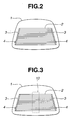
- Fig. 2 is a plan view showing the antifogging glass;
- Fig. 3 is a view similar to Fig. 2, but showing an area for conducting a binarization with a dotted line; and
- Fig. 4 is a schematic view showing a condition in which a voltage is applied to a conductive wire as antenna.
-
- A method of the present invention for finding the existence or nonexistence of disconnection of a conductive wire(s) formed on a plate glass is described in detail, as follows.
- Conductive wires can be formed on a plate glass to have a certain predetermined pattern by applying a conductive paste to the plate glass through screen printing or the like. The resulting conductive wires can serve as heating wires of an antifogging glass for providing antifogging property or as antenna wires of an antenna glass.
- Fig. 1 shows an exemplary apparatus according to the present invention, which is capable of finding the existence or nonexistence of disconnection of
conductive wires 2 formed on anantifogging glass 1 of Fig. 2. - The apparatus has a power source for applying a voltage to the
conductive wires 2. As is seen from Fig. 1, the power source may be a voltage stabilizer or constant voltage device 5 (preferably of direct current) for controlling the amount of heat generation from the conductive wires or the temperature of the conductive wires upon applying a voltage to the conductive wires. - In case that a conductive wire has no disconnection, heat is generated from the conductive wire by applying a voltage thereto. In contrast, in case that a conductive wire has disconnection, no heat is generated. Thus, it is possible by the present invention to find the existence or nonexistence of disconnection of a conductive wire(s) by imaging thermal radiation from the surface of the conductive wire(s) by an infrared image sensor to produce a temperature distribution image. In other words, if no heat generation has been found at a position in the temperature distribution image, which corresponds to the position of a conductive wire, this conductive wire can be judged as having disconnection. In contrast, if a certain predetermined heat generation has been found at such position, the conductive wire can be judged as having no disconnection. This judgement can easily be conducted by comparing the temperature distribution image of a plate glass with an image data showing the pattern of conductive wires of the plate glass, as described hereinafter.
- As is seen from Fig. 2, conductive wires (heating wires) 2 of an
antifogging glass 1 are connected tobus bars 3. Therefore, it is possible to apply a voltage to theconductive wires 2 by usingfeeding terminals 4 of thebus bars 3 or by bringing feeding probes into contact with thebus bars 3. - As is seen from Fig. 4, in case that the conductive wire is an
antenna wire 12 formed on a plate glass (antenna glass) 13, the feeding terminal is often provided only at an end or another position of theantenna wire 12.
In this case, it is possible to apply a voltage to theantenna wire 12 by using at least two probes 11 (three probes in Fig. 4). - The voltage to be applied to the
conductive wire 2 may be adjusted to a value that is appropriate for resistance of theconductive wire 2. If theconductive wire 2 is a heating wire for antifogging glass, the voltage may be from 10V to 50V. - The infrared image sensor of the present invention may be an infrared camera or thermo-tracer. The infrared image sensor may contain an infrared detecting device and an optical system for image formation.
- The above-mentioned judgement with respect to disconnection can be made by checking only the temperature distribution image taken by an infrared image sensor. However, as the number of conductive wires increases in an area of a certain size to have a complicated pattern, it may be difficult to judge whether a first case, in which heat generation is not shown at a particular position of the temperature distribution image due to disconnection of a conductive wire, or a second case, in which heat generation is not shown due to nonexistence of a conductive wire, is true. Thus, it is possible to easily conduct the judgement by comparing the temperature distribution image with an image data showing the pattern (distribution) of conductive wires. This image data may be a first image data obtained by drafting the pattern of the conductive wires, for example, by computer-aided design (CAD). The first image data (digital data) obtained by CAD is suitable, since it can be processed in an image processor. The image data may be a second image data obtained, prior to the voltage application, by imaging thermal radiation from the surface of the conductive wire by an infrared image sensor or digital camera.
- An image itself (taken by an infrared image sensor or digital camera prior to the voltage application) may be compared with the temperature distribution image (taken by an infrared image sensor under the voltage application) for judging whether or not a conductive wire has disconnection. However, it is preferable to subject both of these images to a binarization by an image processor in order to distinguish the image of the conductive wires from the image of other parts of a plate glass.
- The above binarization may be conducted for a part or the entirety of the image in accordance with the range necessary for the disconnection inspection. For example, in case that all of the
heating wires 2 are parallel with each other, it suffices that only the image of a rectangular portion 10 (covering all theheating wires 2 as shown in Fig. 3) is subjected to the binarization. - It is possible to easily compare the temperature distribution image (taken under the voltage application) with a data representing the pattern of the conductive wires by superimposing the temperature distribution image on this data to have these on the same screen. Furthermore, it is possible to conduct a subtraction by an image processor between the temperature distribution image and the data, thereby clearly showing only conductive wires having disconnection on the screen. In this way, it is possible by the present invention to automatically find the existence or nonexistence of disconnection of conductive wires.
- In case that a data representing the pattern of the conductive wires is an image (digital) data obtained by CAD, an infrared image sensor or digital camera, such image data can be used in the above-mentioned superimposition and subtraction. Even in case that a data representing the pattern of the conductive wires is a data (analogue data) obtained by drafting the pattern on paper or the like, it is preferable to convert such analogue data to an image data (digital data) by using a digital camera or the like.
- The following nonlimitative Example is illustrative of the present invention.
- Prior to the voltage application, the image of the pattern of
heating wires 2 of an antifogging glass 1 (shown in Fig. 2) was taken by an infrared image sensor (i.e., an infrared camera of Nippon Avionics Co., Ltd.) 7 of Fig. 1. - Then, a voltage of 20V was applied by connecting a voltage stabilizer (constant voltage device) 5 to
feeding terminals 4 of anantifogging glass 1 throughfeeding wires 6. Under this condition, the image of the pattern of theheating wires 2 was taken by theinfrared camera 7. This image taken by theinfrared camera 7 was shown in amonitor 8 and compared with the image prior to the voltage application to find the existence or nonexistence of disconnection of the heating wires. - The two images (prior to and under the voltage application) obtained in Example 1 were subjected to a binarization by an
image processor 9 made by Yokogawa MAT Corporation, thereby obtaining two image data showing only the heating wires. These two image data were subjected a subtraction, and the result was shown in themonitor 8. In fact, each image remaining after the subtraction was judged as representing one heating wire having disconnection. This judgement was conducted automatically. - The same steps as those of Examples 1 and 2 were conducted sequentially, except in that the infrared camera of Example 1 was replaced with a thermo-tracer made by NEC san-ei Instruments Co. With this, it was possible to find the existence or nonexistence of disconnection of the conductive wires (heating wires) 2.
- The entire contents of Japanese Patent Application No. 2002-015206 (filed January 24, 2002), which is a basic Japanese application of the present application, are incorporated herein by reference.
Claims (9)
- A method for finding disconnection of a conductive wire formed on a plate glass, the method comprising the steps of:(a) applying a voltage to the conductive wire; and(b) imaging thermal radiation from a surface of the conductive wire by an infrared image sensor, while the step (a) is conducted, thereby producing a temperature distribution image.
- A method according to claim 1, wherein the temperature distribution image is subjected to a binarization by an image processor.
- A method according to claim 1 or 2, wherein the temperature distribution image is compared with a data representing a pattern of the conductive wire.
- A method according to claim 3, wherein the data is a first image data obtained by drafting the pattern of the conductive wire.
- A method according to claim 3, wherein the data is a second image data obtained, prior to the step (a), by imaging thermal radiation from the surface of the conductive wire by the infrared image sensor.
- A method according to claim 3, 4 or 5, wherein the comparison is conducted by superimposing the temperature distribution image on the data.
- A method according to claim 3, 4, 5 or 6, wherein the comparison is conducted by an image data subtraction between the temperature distribution image and the data.
- An apparatus for finding disconnection of a conductive wire formed on a plate glass, the apparatus comprising:a power source for applying a voltage to the conductive wire; andan infrared image sensor for imaging thermal radiation from a surface of the conductive wire, thereby producing a temperature distribution image.
- An apparatus according to claim 8, wherein the infrared image sensor is an infrared camera.
Priority Applications (1)
| Application Number | Priority Date | Filing Date | Title |
|---|---|---|---|
| EP03016807A EP1500941A1 (en) | 2003-07-23 | 2003-07-23 | Method for finding disconnection of conductive wires formed on plate glass and apparatus therefor |
Applications Claiming Priority (1)
| Application Number | Priority Date | Filing Date | Title |
|---|---|---|---|
| EP03016807A EP1500941A1 (en) | 2003-07-23 | 2003-07-23 | Method for finding disconnection of conductive wires formed on plate glass and apparatus therefor |
Publications (1)
| Publication Number | Publication Date |
|---|---|
| EP1500941A1 true EP1500941A1 (en) | 2005-01-26 |
Family
ID=33483936
Family Applications (1)
| Application Number | Title | Priority Date | Filing Date |
|---|---|---|---|
| EP03016807A Withdrawn EP1500941A1 (en) | 2003-07-23 | 2003-07-23 | Method for finding disconnection of conductive wires formed on plate glass and apparatus therefor |
Country Status (1)
| Country | Link |
|---|---|
| EP (1) | EP1500941A1 (en) |
Cited By (1)
| Publication number | Priority date | Publication date | Assignee | Title |
|---|---|---|---|---|
| CN105548747A (en) * | 2015-12-04 | 2016-05-04 | 国网技术学院 | Equipment fault identification system and method based on infrared temperature measurement technology |
Citations (4)
| Publication number | Priority date | Publication date | Assignee | Title |
|---|---|---|---|---|
| EP0535881A1 (en) * | 1991-10-01 | 1993-04-07 | Cincinnati Electronics Corporation | Infrared inspection system and method |
| US5309108A (en) * | 1991-07-30 | 1994-05-03 | Hitachi, Ltd. | Method of inspecting thin film transistor liquid crystal substrate and apparatus therefor |
| JPH06249905A (en) * | 1993-02-24 | 1994-09-09 | Central Glass Co Ltd | Method and apparatus for inspection of disconnection in blur-protected glass |
| WO2001007901A1 (en) * | 1999-07-23 | 2001-02-01 | Telcordia Technologies, Inc. | Infrared thermographic method for process monitoring and control of multilayer conductive compositions |
-
2003
- 2003-07-23 EP EP03016807A patent/EP1500941A1/en not_active Withdrawn
Patent Citations (4)
| Publication number | Priority date | Publication date | Assignee | Title |
|---|---|---|---|---|
| US5309108A (en) * | 1991-07-30 | 1994-05-03 | Hitachi, Ltd. | Method of inspecting thin film transistor liquid crystal substrate and apparatus therefor |
| EP0535881A1 (en) * | 1991-10-01 | 1993-04-07 | Cincinnati Electronics Corporation | Infrared inspection system and method |
| JPH06249905A (en) * | 1993-02-24 | 1994-09-09 | Central Glass Co Ltd | Method and apparatus for inspection of disconnection in blur-protected glass |
| WO2001007901A1 (en) * | 1999-07-23 | 2001-02-01 | Telcordia Technologies, Inc. | Infrared thermographic method for process monitoring and control of multilayer conductive compositions |
Cited By (1)
| Publication number | Priority date | Publication date | Assignee | Title |
|---|---|---|---|---|
| CN105548747A (en) * | 2015-12-04 | 2016-05-04 | 国网技术学院 | Equipment fault identification system and method based on infrared temperature measurement technology |
Similar Documents
| Publication | Publication Date | Title |
|---|---|---|
| US7332718B2 (en) | Method for finding disconnection of conductive wires formed on plate glass and apparatus therefor | |
| US5293220A (en) | Method for inspecting stripped condition of electric wire | |
| EP2467704B1 (en) | Heatable glazing inspection | |
| US8345951B2 (en) | Image binarizing method, image processing device, and computer program | |
| US20160342054A1 (en) | Method and device for repairing metal wire | |
| KR960002145B1 (en) | Detection method of tft lcd panel and the device | |
| JP5128699B1 (en) | Wiring inspection method and wiring inspection apparatus | |
| US7537378B2 (en) | Wire disconnection inspecting device and method | |
| US20100271633A1 (en) | Semiconductor test instrument and the method to test semiconductor | |
| KR20100028275A (en) | Apparatus and method for inspecting electrode lines of falt panel display | |
| US20040234119A1 (en) | System for and method of analyzing surface condition of PCB using RGB colors | |
| US6614922B1 (en) | Wire pattern test system | |
| CA2364564A1 (en) | Short-circuit locator for printed circuit boards using a visible camera and an ir camera | |
| US6881595B2 (en) | Method of and apparatus for testing the quality of printed circuits | |
| JP2009042022A (en) | Image inspection device | |
| US6005966A (en) | Method and apparatus for multi-stream detection of high density metalization layers of multilayer structures having low contrast | |
| JP2788346B2 (en) | Printed wiring board inspection equipment | |
| CA2363171A1 (en) | Short-circuit locator for printed circuit boards using a visible-nir camera | |
| CN117687385B (en) | Automatic test method and system applied to flat PCBA control module | |
| JP5011991B2 (en) | Lead frame inspection method and apparatus | |
| JP3953856B2 (en) | Heater heat generation inspection method and heater automatic inspection machine | |
| JPH08222043A (en) | Flat cable inspection method and device | |
| JP2000097983A (en) | Inspection method of wiring part in wiring integrated suspension | |
| JP4491722B2 (en) | Film inspection equipment | |
| JP2000149027A (en) | Line laying checking device and method |
Legal Events
| Date | Code | Title | Description |
|---|---|---|---|
| PUAI | Public reference made under article 153(3) epc to a published international application that has entered the european phase |
Free format text: ORIGINAL CODE: 0009012 |
|
| 17P | Request for examination filed |
Effective date: 20040505 |
|
| AK | Designated contracting states |
Kind code of ref document: A1 Designated state(s): DE FR GB |
|
| AX | Request for extension of the european patent |
Extension state: AL LT LV MK |
|
| AKX | Designation fees paid |
Designated state(s): DE FR GB |
|
| 17Q | First examination report despatched |
Effective date: 20071213 |
|
| STAA | Information on the status of an ep patent application or granted ep patent |
Free format text: STATUS: THE APPLICATION IS DEEMED TO BE WITHDRAWN |
|
| 18D | Application deemed to be withdrawn |
Effective date: 20130201 |