EP1500614A1 - Rod retaining snap rod with enlarged retaining ring - Google Patents
Rod retaining snap rod with enlarged retaining ring Download PDFInfo
- Publication number
- EP1500614A1 EP1500614A1 EP04405463A EP04405463A EP1500614A1 EP 1500614 A1 EP1500614 A1 EP 1500614A1 EP 04405463 A EP04405463 A EP 04405463A EP 04405463 A EP04405463 A EP 04405463A EP 1500614 A1 EP1500614 A1 EP 1500614A1
- Authority
- EP
- European Patent Office
- Prior art keywords
- belt
- pivot rod
- diameter
- link
- retaining ring
- Prior art date
- Legal status (The legal status is an assumption and is not a legal conclusion. Google has not performed a legal analysis and makes no representation as to the accuracy of the status listed.)
- Granted
Links
- 238000003780 insertion Methods 0.000 description 5
- 230000037431 insertion Effects 0.000 description 5
- 238000009434 installation Methods 0.000 description 5
- 230000014759 maintenance of location Effects 0.000 description 3
- 239000004033 plastic Substances 0.000 description 3
- 238000005452 bending Methods 0.000 description 2
- 230000001419 dependent effect Effects 0.000 description 1
- 230000003670 easy-to-clean Effects 0.000 description 1
- 235000013305 food Nutrition 0.000 description 1
- 238000004519 manufacturing process Methods 0.000 description 1
- 238000005007 materials handling Methods 0.000 description 1
- 239000002184 metal Substances 0.000 description 1
- 238000012986 modification Methods 0.000 description 1
- 230000004048 modification Effects 0.000 description 1
- 239000002991 molded plastic Substances 0.000 description 1
- 230000000717 retained effect Effects 0.000 description 1
Images



Classifications
-
- B—PERFORMING OPERATIONS; TRANSPORTING
- B65—CONVEYING; PACKING; STORING; HANDLING THIN OR FILAMENTARY MATERIAL
- B65G—TRANSPORT OR STORAGE DEVICES, e.g. CONVEYORS FOR LOADING OR TIPPING, SHOP CONVEYOR SYSTEMS OR PNEUMATIC TUBE CONVEYORS
- B65G17/00—Conveyors having an endless traction element, e.g. a chain, transmitting movement to a continuous or substantially-continuous load-carrying surface or to a series of individual load-carriers; Endless-chain conveyors in which the chains form the load-carrying surface
- B65G17/06—Conveyors having an endless traction element, e.g. a chain, transmitting movement to a continuous or substantially-continuous load-carrying surface or to a series of individual load-carriers; Endless-chain conveyors in which the chains form the load-carrying surface having a load-carrying surface formed by a series of interconnected, e.g. longitudinal, links, plates, or platforms
- B65G17/08—Conveyors having an endless traction element, e.g. a chain, transmitting movement to a continuous or substantially-continuous load-carrying surface or to a series of individual load-carriers; Endless-chain conveyors in which the chains form the load-carrying surface having a load-carrying surface formed by a series of interconnected, e.g. longitudinal, links, plates, or platforms the surface being formed by the traction element
-
- B—PERFORMING OPERATIONS; TRANSPORTING
- B65—CONVEYING; PACKING; STORING; HANDLING THIN OR FILAMENTARY MATERIAL
- B65G—TRANSPORT OR STORAGE DEVICES, e.g. CONVEYORS FOR LOADING OR TIPPING, SHOP CONVEYOR SYSTEMS OR PNEUMATIC TUBE CONVEYORS
- B65G17/00—Conveyors having an endless traction element, e.g. a chain, transmitting movement to a continuous or substantially-continuous load-carrying surface or to a series of individual load-carriers; Endless-chain conveyors in which the chains form the load-carrying surface
- B65G17/06—Conveyors having an endless traction element, e.g. a chain, transmitting movement to a continuous or substantially-continuous load-carrying surface or to a series of individual load-carriers; Endless-chain conveyors in which the chains form the load-carrying surface having a load-carrying surface formed by a series of interconnected, e.g. longitudinal, links, plates, or platforms
- B65G17/08—Conveyors having an endless traction element, e.g. a chain, transmitting movement to a continuous or substantially-continuous load-carrying surface or to a series of individual load-carriers; Endless-chain conveyors in which the chains form the load-carrying surface having a load-carrying surface formed by a series of interconnected, e.g. longitudinal, links, plates, or platforms the surface being formed by the traction element
- B65G17/086—Conveyors having an endless traction element, e.g. a chain, transmitting movement to a continuous or substantially-continuous load-carrying surface or to a series of individual load-carriers; Endless-chain conveyors in which the chains form the load-carrying surface having a load-carrying surface formed by a series of interconnected, e.g. longitudinal, links, plates, or platforms the surface being formed by the traction element specially adapted to follow a curved path
-
- B—PERFORMING OPERATIONS; TRANSPORTING
- B65—CONVEYING; PACKING; STORING; HANDLING THIN OR FILAMENTARY MATERIAL
- B65G—TRANSPORT OR STORAGE DEVICES, e.g. CONVEYORS FOR LOADING OR TIPPING, SHOP CONVEYOR SYSTEMS OR PNEUMATIC TUBE CONVEYORS
- B65G17/00—Conveyors having an endless traction element, e.g. a chain, transmitting movement to a continuous or substantially-continuous load-carrying surface or to a series of individual load-carriers; Endless-chain conveyors in which the chains form the load-carrying surface
- B65G17/30—Details; Auxiliary devices
- B65G17/38—Chains or like traction elements; Connections between traction elements and load-carriers
- B65G17/40—Chains acting as load-carriers
-
- B—PERFORMING OPERATIONS; TRANSPORTING
- B65—CONVEYING; PACKING; STORING; HANDLING THIN OR FILAMENTARY MATERIAL
- B65G—TRANSPORT OR STORAGE DEVICES, e.g. CONVEYORS FOR LOADING OR TIPPING, SHOP CONVEYOR SYSTEMS OR PNEUMATIC TUBE CONVEYORS
- B65G21/00—Supporting or protective framework or housings for endless load-carriers or traction elements of belt or chain conveyors
- B65G21/16—Supporting or protective framework or housings for endless load-carriers or traction elements of belt or chain conveyors for conveyors having endless load-carriers movable in curved paths
- B65G21/18—Supporting or protective framework or housings for endless load-carriers or traction elements of belt or chain conveyors for conveyors having endless load-carriers movable in curved paths in three-dimensionally curved paths
-
- B—PERFORMING OPERATIONS; TRANSPORTING
- B65—CONVEYING; PACKING; STORING; HANDLING THIN OR FILAMENTARY MATERIAL
- B65G—TRANSPORT OR STORAGE DEVICES, e.g. CONVEYORS FOR LOADING OR TIPPING, SHOP CONVEYOR SYSTEMS OR PNEUMATIC TUBE CONVEYORS
- B65G2207/00—Indexing codes relating to constructional details, configuration and additional features of a handling device, e.g. Conveyors
- B65G2207/12—Chain pin retainers
Definitions
- the present invention relates to modular conveying apparatus, in particular a modular belt.
- Modular plastic conveyor belts are made up of molded plastic modular links, or belt modules, that can be arranged side by side in rows of selectable width.
- a series of spaced apart link ends extending from each side of the modules include aligned apertures to accommodate a pivot rod.
- the link ends along one end of a row of modules are interconnected with link ends of an adjacent row.
- a pivot rod journaled in the aligned apertures of the side-by-side and end-to-end connected modules forms a hinge between adjacent rows. Rows of belt modules are then connected together to form an endless conveyor belt capable of articulating about a drive sprocket.
- the retention of the pivot rod is an important feature of the modular plastic conveyor belts. Rod retention can be accomplished by enlarging the heads of the pivot rods at both ends but such would not allow for disassembly without destroying the rod head. Headless rods have been used for easier production and belt assembly. These type of rods must be blocked at both ends of the belt during use. In addition headless rods are often difficult to remove for disassembly.
- One approach to rod retention is to have a head at one end of a rod and a headless section at the opposite end.
- the headed rod is furnished with a rod retaining ring disposed on the shaft at a distance from the head portion of the rod.
- the rod is inserted through the pivot holes of the module links, which are all exactly the same diameter.
- the retaining ring is just a little bit larger in diameter than the pivot hole of the outermost link, such that the ring may be forced through the pivot hole of the outermost link end and is able to expand behind the link.
- the rod is kept firmly in position by the retaining ring.
- the system described above has the drawback that it requires tight tolerances of the hole diameter of the outermost link and the retaining ring diameter. In practice, there is a risk that the rod does not retain well enough or is retained tightly and cannot be easily disassembled. In addition, if the retaining ring is a little too large, it may be sheared off when inserted.
- the present invention meets the above-described need by providing a snap rod system such that the retaining ring can be made larger in order to increase the size of the shoulder which engages behind the link face.
- the bore of the outermost link needs to be enlarged accordingly in order to allow the larger retaining ring to be moved through the bore. Due to the larger difference between the retaining ring and the rod diameter, the tolerance becomes less critical.
- the bore of the outermost link end is slightly eccentric in such a way that the enlarged shoulder of the retaining ring will be clearly overlapping the link face when assembled. When the belt is under tension the rod will be firmly forced into this retaining position, without losing the ability to transmit the belt pull.
- a modular belt 10 is formed from a plurality of belt modules as will be evident to those of ordinary skill in the art.
- the outermost modules 13, 16 are shown.
- the belt 10 may be formed into varying widths in bricklayed fashion in a direction perpendicular to the direction of belt travel 34.
- Each module 13, 16 has a module body 20 with a first and second plurality of link ends 22, 25 disposed in the middle of the module with respect to the outer edge 12 shown at the top of Figure 1.
- Each link end 22, 25 has opposed side walls 23, 24 defining a first transverse thickness 21.
- the first transverse thickness 21 is connected to the intermediate section 26 of the module body 20 at a first proximal portion 27.
- the transverse thickness extends from the intermediate section 26 in a direction of belt travel to a first distal portion 29.
- the link ends 22, 25 include openings 28, 31 disposed transverse to the direction of belt travel 34.
- the openings 28 and 31 receive the pivot rod 19 when adjacent belt modules 13, 16 are intercalated as shown in the figure.
- the pivot rod 19 is typically round and has a diameter 30 such that the modules 13, 16 are capable of pivoting relative to each other for articulating about a sprocket (not shown).
- the pivot rod 19 has an end portion 46 with a diameter 47 that is greater than the diameter 30 of the pivot rod 19.
- the pivot rod 19 also includes a retaining ring 60 spaced apart longitudinally from the end portion 46.
- the retaining ring 60 has a diameter D R that is larger than the diameter of the pivot rod 19 and may be formed with a chamfered or beveled edge 63.
- Outermost link end 40 of module 16 is disposed toward the edge 12 of belt 10.
- the outermost link end 40 has a recessed portion 43 that is capable of receiving end portion 46 of pivot rod 19.
- the pivot rod 19 is installed in the belt 10 in the direction indicated by arrow 49, the end portion 46 is received in the recessed portion 43 and abuts with the portion of the link end surrounding aperture 52 as shown in Fig. 4.
- Link end 40 has an opening 52 with a diameter D 1 that is approximately equal to or slightly smaller than the diameter D R of the ring 60 but is larger than the diameter D 2 of openings 28, 31.
- Belt module 13 also has a specially formed outermost link end 55 having a recessed portion 56 and an opening 31 with a diameter D 2 .
- the central longitudinal axis 65 of aperture 52 is offset from the central longitudinal axis 67 of openings 28, 31 such that upon insertion, the pivot rod 19 is bent as shown in Fig. 3.
- the pivot rod 19 is bent during insertion such that once the ring 60 clears aperture 52, the enlarged shoulder 75 overlaps the link face surrounding aperture 52 as shown in the circled area 76 in Fig. 4.
- the axial misalignment between the apertures 52 and 31 ensures that the ring 60 does not exit from the aligned modules 13 and 16 after installation.
- Figs. 2-4 illustrate the position of the pivot rod 19 and the modules 13 and 16 during various stages of the installation of the pivot rod 19.
- the pivot rod 19 is shown at the maximum insertion point prior to bending the body or shaft of the pivot rod 19.
- the rod 19 has been inserted in the direction of arrow 49 until the beveled edge 63 of the retaining ring 60 engages with the edge of the opening 52 on the left hand side of the figure.
- retaining ring 60 aligns with the opening 52.
- the retaining ring 60 is sized to frictionally engage with the inside walls of opening 52 during insertion. Accordingly, the retaining ring may be roughly equal to or slightly larger in diameter D R than the inside diameter D 1 of opening 52. As shown, the left hand side of the beveled edge 63 clears the opening in Fig. 3 so that the retaining ring 60 may be passed through the opening 52.
- FIG. 5 an alternate embodiment of the modular belt of the present invention is shown.
- the overlapping area 100 located between the outermost link end 103 on the first belt module 104 and the rod retaining ring 106 defines the locking behavior of the snap rod.
- the offset 107 between the pivot rod center axis 109 and the central axis 111 of opening 112 in the outermost link end 103 for the retaining ring 106 is a parameter that affects the locking behavior.
- This offset 107 can be increased by reducing the diameter D 3 of the rod 118 to a diameter D 4 between the head 121 and the retaining ring 106.
- the outermost link end 103 has a recessed portion 122 that receives the head 121.
- the opening 112 in the outermost link end 103 is larger than the openings 127 in the plurality of link ends 130.
- the second belt module 133 also has an outermost link end 136 having a recessed portion 139.
- the recessed portion 139 in the second belt module 133 receives the retaining ring 106 when the first and second belt modules 104, 133 are intercalated and connected by the pivot rod 118.
- the outermost link end 136 on the second belt module 133 has a pivot rod opening 140 with a diameter 143 that is approximately equal to the diameter of the openings 127 in the first belt module 104.
- Fig. 6 the offset 107 is shown from an end view of the intercalated belt modules.
- the pivot rod axis 109 and the central axis 111 of the opening 112 are shown.
- the pivot rod 118 may be removed by use of a screw driver 200.
- the screw driver 200 may be inserted under the head 121 of the pivot rod 118 to provide leverage for bending the rod 118 to align it with the opening 112 in the outermost link end 103 in the first module 104. Once the retaining ring 106 is aligned with the opening 112 the pivot rod 118 may be removed by sliding it outward in the direction indicated by arrow 203.
- a belt 300 is formed from modules 303 and 306.
- the modules have outer link ends 309, 312.
- Link end 309 on module 306 has extra width to accommodate an internal opening 315 for receiving retaining ring 360 on pivot rod 319.
- Link end 312 on module 303 intercalates adjacent to link end 309 as shown.
- the link end 309 also includes a recessed portion 318 for receiving end portion 346 of pivot rod 319.
- Link end 309 also includes an opening 321 having the same diameter as opening 315. Openings 315 and 321 have a diameter D 1 that is approximately equal to or smaller than the diameter D r of ring 360 which is formed with a chamfered or beveled edge 363. The link end 312 and the link ends disposed toward the middle of the belt have openings with a Diameter D 2 that is smaller than D 1 . The longitudinal axis 325 of openings 315 and 321 is offset from the longitudinal axis 330 of the opening in link end 312 and the openings 350 toward the middle of the belt module.
- the pivot rod 319 has to be bent and once the ring 360 clears the opening 315 it shifts to the left with respect to Fig. 8 such that shoulder 375 engages the link surface around opening 315.
- Fig. 8 may also be provided with a pivot rod 118 (Fig. 5) having different diameters located above and below the retaining ring 106.
- the diameter of the rod between the retaining ring and the head is smaller than the diameter of the rod between the retaining ring and the second end of the rod.
Landscapes
- Engineering & Computer Science (AREA)
- Mechanical Engineering (AREA)
- Chain Conveyers (AREA)
- Clamps And Clips (AREA)
- Insertion Pins And Rivets (AREA)
- Supports Or Holders For Household Use (AREA)
- Adornments (AREA)
- Slide Fasteners, Snap Fasteners, And Hook Fasteners (AREA)
- Supports For Pipes And Cables (AREA)
- Hooks, Suction Cups, And Attachment By Adhesive Means (AREA)
- Harvester Elements (AREA)
Abstract
Description
- The present invention relates to modular conveying apparatus, in particular a modular belt.
- Because they do not corrode, are light weight, and are easy to clean, unlike metal conveyor belts, plastic conveyor belts are used widely, especially in materials handling and conveying food products. Modular plastic conveyor belts are made up of molded plastic modular links, or belt modules, that can be arranged side by side in rows of selectable width. A series of spaced apart link ends extending from each side of the modules include aligned apertures to accommodate a pivot rod. The link ends along one end of a row of modules are interconnected with link ends of an adjacent row. A pivot rod journaled in the aligned apertures of the side-by-side and end-to-end connected modules forms a hinge between adjacent rows. Rows of belt modules are then connected together to form an endless conveyor belt capable of articulating about a drive sprocket.
- The retention of the pivot rod is an important feature of the modular plastic conveyor belts. Rod retention can be accomplished by enlarging the heads of the pivot rods at both ends but such would not allow for disassembly without destroying the rod head. Headless rods have been used for easier production and belt assembly. These type of rods must be blocked at both ends of the belt during use. In addition headless rods are often difficult to remove for disassembly.
- One approach to rod retention is to have a head at one end of a rod and a headless section at the opposite end. The headed rod is furnished with a rod retaining ring disposed on the shaft at a distance from the head portion of the rod. The rod is inserted through the pivot holes of the module links, which are all exactly the same diameter. The retaining ring is just a little bit larger in diameter than the pivot hole of the outermost link, such that the ring may be forced through the pivot hole of the outermost link end and is able to expand behind the link. In this arrangement the rod is kept firmly in position by the retaining ring. The system described above has the drawback that it requires tight tolerances of the hole diameter of the outermost link and the retaining ring diameter. In practice, there is a risk that the rod does not retain well enough or is retained tightly and cannot be easily disassembled. In addition, if the retaining ring is a little too large, it may be sheared off when inserted.
- What is needed is a device that makes the above-described tolerances less critical.
- This object is achieved by the modular belt according to independent Claim 1 and the belt module according to independent Claim 6. Preferred embodiments are defined in the dependent claims.
- The present invention meets the above-described need by providing a snap rod system such that the retaining ring can be made larger in order to increase the size of the shoulder which engages behind the link face. At the same time due to the larger ring diameter the bore of the outermost link needs to be enlarged accordingly in order to allow the larger retaining ring to be moved through the bore. Due to the larger difference between the retaining ring and the rod diameter, the tolerance becomes less critical. In one embodiment, the bore of the outermost link end is slightly eccentric in such a way that the enlarged shoulder of the retaining ring will be clearly overlapping the link face when assembled. When the belt is under tension the rod will be firmly forced into this retaining position, without losing the ability to transmit the belt pull.
- The invention is illustrated in the drawings in which like reference characters designate the same or similar parts throughout the figures of which:
- Fig. 1 is a cross-sectional plan view of a belt and pivot rod of the present invention with the pivot rod extending from the end of the belt prior to installation;
- Fig. 2 is a cross-section plan view of the belt and pivot rod of Fig. 1 during the initial stage of installation of the pivot rod;
- Fig. 3 is a cross-sectional plan view of the belt and pivot rod during a later stage of installation;
- Fig. 4 is a cross-sectional plan view of the belt and pivot rod of Fig. 1 shown in the installed configuration;
- Fig. 5 is a cross-sectional view of the belt and pivot rod of an alternate embodiment of the present invention shown in the installed configuration;
- Fig. 6 is an end view of the belt with the pivot rod removed for clarity;
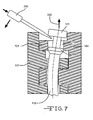
- Fig. 7 is a cross-sectional view of the belt shown in Fig. 5 during removal of the pivot rod with a screw driver; and,
- Fig. 8 is a cross-sectional plan view of an alternate embodiment of the present invention.
-
- In Figs. 1-4, a
modular belt 10 is formed from a plurality of belt modules as will be evident to those of ordinary skill in the art. In Fig. 1, theoutermost modules belt 10 may be formed into varying widths in bricklayed fashion in a direction perpendicular to the direction ofbelt travel 34. - Each
module module body 20 with a first and second plurality oflink ends outer edge 12 shown at the top of Figure 1. Eachlink end opposed side walls transverse thickness 21. The firsttransverse thickness 21 is connected to theintermediate section 26 of themodule body 20 at a firstproximal portion 27. The transverse thickness extends from theintermediate section 26 in a direction of belt travel to a firstdistal portion 29. - The link ends 22, 25 include
openings belt travel 34. Theopenings pivot rod 19 whenadjacent belt modules - The
pivot rod 19 is typically round and has adiameter 30 such that themodules pivot rod 19 has anend portion 46 with adiameter 47 that is greater than thediameter 30 of thepivot rod 19. Thepivot rod 19 also includes aretaining ring 60 spaced apart longitudinally from theend portion 46. Theretaining ring 60 has a diameter DR that is larger than the diameter of thepivot rod 19 and may be formed with a chamfered orbeveled edge 63. -
Outermost link end 40 ofmodule 16 is disposed toward theedge 12 ofbelt 10. Theoutermost link end 40 has arecessed portion 43 that is capable of receivingend portion 46 ofpivot rod 19. When thepivot rod 19 is installed in thebelt 10 in the direction indicated byarrow 49, theend portion 46 is received in therecessed portion 43 and abuts with the portion of the linkend surrounding aperture 52 as shown in Fig. 4. -
Link end 40 has anopening 52 with a diameter D1 that is approximately equal to or slightly smaller than the diameter DR of thering 60 but is larger than the diameter D2 ofopenings -
Belt module 13 also has a specially formedoutermost link end 55 having a recessedportion 56 and anopening 31 with a diameter D2. - The central
longitudinal axis 65 ofaperture 52 is offset from the centrallongitudinal axis 67 ofopenings pivot rod 19 is bent as shown in Fig. 3. Thepivot rod 19 is bent during insertion such that once thering 60 clearsaperture 52, the enlargedshoulder 75 overlaps the linkface surrounding aperture 52 as shown in the circledarea 76 in Fig. 4. The axial misalignment between theapertures ring 60 does not exit from the alignedmodules - Figs. 2-4 illustrate the position of the
pivot rod 19 and themodules pivot rod 19. In Fig. 2, thepivot rod 19 is shown at the maximum insertion point prior to bending the body or shaft of thepivot rod 19. Therod 19 has been inserted in the direction ofarrow 49 until thebeveled edge 63 of the retainingring 60 engages with the edge of theopening 52 on the left hand side of the figure. - Turning to Fig. 3, deflection of the
pivot rod 19 to the right side of opening 52 causes thepivot rod 19 to bend such that the retainingring 60 aligns with theopening 52. The retainingring 60 is sized to frictionally engage with the inside walls of opening 52 during insertion. Accordingly, the retaining ring may be roughly equal to or slightly larger in diameter DR than the inside diameter D1 of opening 52. As shown, the left hand side of thebeveled edge 63 clears the opening in Fig. 3 so that the retainingring 60 may be passed through theopening 52. - In Fig. 4, the
pivot rod 19 has been inserted such that the retainingring 60 has passed all the way through opening 52 and has "snapped" back to the left in the area shown incircle 76. Once the left edge of the retainingring 60 clears the end of theopening 52, thepivot rod 19 returns to its straight configuration. In this position, thebelt modules ring 60. - Turning to Fig. 5, an alternate embodiment of the modular belt of the present invention is shown. The overlapping
area 100 located between theoutermost link end 103 on thefirst belt module 104 and therod retaining ring 106 defines the locking behavior of the snap rod. The offset 107 between the pivotrod center axis 109 and thecentral axis 111 of opening 112 in theoutermost link end 103 for the retainingring 106 is a parameter that affects the locking behavior. This offset 107 can be increased by reducing the diameter D3 of therod 118 to a diameter D4 between thehead 121 and the retainingring 106. Theoutermost link end 103 has a recessedportion 122 that receives thehead 121. Theopening 112 in theoutermost link end 103 is larger than theopenings 127 in the plurality of link ends 130. - The
second belt module 133 also has anoutermost link end 136 having a recessedportion 139. The recessedportion 139 in thesecond belt module 133 receives the retainingring 106 when the first andsecond belt modules pivot rod 118. Theoutermost link end 136 on thesecond belt module 133 has a pivot rod opening 140 with adiameter 143 that is approximately equal to the diameter of theopenings 127 in thefirst belt module 104. - In Fig. 6, the offset 107 is shown from an end view of the intercalated belt modules. The
pivot rod axis 109 and thecentral axis 111 of theopening 112 are shown. - As shown in Fig. 7, the
pivot rod 118 may be removed by use of ascrew driver 200. Thescrew driver 200 may be inserted under thehead 121 of thepivot rod 118 to provide leverage for bending therod 118 to align it with theopening 112 in theoutermost link end 103 in thefirst module 104. Once the retainingring 106 is aligned with theopening 112 thepivot rod 118 may be removed by sliding it outward in the direction indicated byarrow 203. - Turning to Fig. 8, an alternate embodiment of the present invention is shown. A
belt 300 is formed frommodules Link end 309 onmodule 306 has extra width to accommodate aninternal opening 315 for receiving retainingring 360 onpivot rod 319.Link end 312 onmodule 303 intercalates adjacent to linkend 309 as shown. Thelink end 309 also includes a recessedportion 318 for receivingend portion 346 ofpivot rod 319. -
Link end 309 also includes anopening 321 having the same diameter asopening 315.Openings ring 360 which is formed with a chamfered orbeveled edge 363. Thelink end 312 and the link ends disposed toward the middle of the belt have openings with a Diameter D2 that is smaller than D1. Thelongitudinal axis 325 ofopenings longitudinal axis 330 of the opening inlink end 312 and theopenings 350 toward the middle of the belt module. - Accordingly, during insertion of the
pivot rod 319, thepivot rod 319 has to be bent and once thering 360 clears theopening 315 it shifts to the left with respect to Fig. 8 such thatshoulder 375 engages the link surface aroundopening 315. - The embodiment of Fig. 8 may also be provided with a pivot rod 118 (Fig. 5) having different diameters located above and below the retaining
ring 106. In the example shown, the diameter of the rod between the retaining ring and the head is smaller than the diameter of the rod between the retaining ring and the second end of the rod. - While the invention has been described in connection with certain embodiments, it is not intended to limit the scope of the invention to the particular forms set forth, but, on the contrary, it is intended to cover such alternatives, modifications, and equivalents as may be included within the scope of the invention as defined by the appended claims.
Claims (9)
- A modular belt (10), comprising:a first belt module (16; 104) having a first plurality of link ends (22; 130), each link end (22; 130) having opposed side walls (23, 24) providing a first transverse thickness (21) connected to an intermediate section (26) at a first proximal portion (27) and extending from the intermediate section (26) in a direction of belt travel (34) to a first distal portion (29) at the link ends (22; 130), the first plurality of link ends (22; 130) having first openings (28; 127) through the first transverse thickness (21) between and to the opposed side walls (23, 24), the first belt module (16; 104) having an outermost link end (40; 103) having opposed side walls providing a second transverse thickness connected to the intermediate section (26) at a second proximal portion and extending from the intermediate section (26) in a direction of belt travel (34) to a second distal portion at the link end (40; 103), the outermost link end (40; 103) having a second opening (52; 112) through the second transverse thickness between and to the opposed side walls, the second transverse thickness being less than the first transverse thickness, the second opening (52; 112) having an inner diameter (D1) that is greater than an inner diameter (D2) of the first openings (22; 127), the second opening (52; 112) having a central longitudinal axis (65; 111) that is offset (107) in the direction of belt travel (34) from a central longitudinal axis (67) of the first openings (22; 130);a second belt module (13; 133) having a first plurality of link ends (25), each link end (25) having opposed side walls providing a first transverse thickness connected to an intermediate section at a first proximal portion and extending from the intermediate section in a direction of belt travel (34) to a first distal portion at the link ends (25), the first plurality of link ends (25) having first openings (31) through the first transverse thickness between and to the opposed sidewalls, the second belt module (13; 133) having an outermost link end (55; 136) having opposed side walls providing a second transverse thickness connected to the intermediate section at a second proximal portion and extending from the intermediate section in a direction of belt travel (34) to a second distal portion at the link end, the second transverse thickness being less than the first transverse thickness such that a recessed portion (56; 139) is formed in the second belt module (13; 133); and,a pivot rod (19; 118) having an elongate body with a first diameter (30; D3), the pivot rod (19; 118) having a first end disposed opposite from a second end, the pivot rod (19; 118) having a longitudinal axis disposed transverse to the direction of belt travel (34), the pivot rod (19; 118) having a head (46; 121) with a diameter (47) greater than the first diameter (30; D3) and having a retaining ring (60; 106) disposed in spaced apart relation to the head (46; 121) in the direction of the longitudinal axis, the pivot rod (19; 118) capable of being disposed through the first and second openings (31, 28, 52; 127, 112) in adjacent first and second belt modules (16, 13; 104, 133) such that the retaining ring (60; 106) is disposed in the recessed portion (56; 139) in the second module (13; 133) abutting against one of the side walls of the outermost link end (40; 103) of the first module (16; 104) and the head (46; 121) is disposed against the opposite side wall of the outermost link end (40; 103) of the first module (16; 104) when the first and second modules (16, 13; 104, 133) are intercalated.
- Modular belt according to Claim 1, wherein the retaining ring (60; 106) has a diameter (DR) that is larger than the inner diameter (D1) of the second opening (52; 112) in the first belt module (16; 104).
- Modular belt according to Claim 1 or 2, wherein the first openings (31) in the second belt module (13; 133) have an inner diameter (D2) that is substantially equal to the inner diameter (D2) of the first openings (28; 127) in the first belt module (16; 104).
- Modular belt according to anyone of Claims 1 to 3, wherein the retaining ring (60; 106) has a beveled edge (63).
- Modular belt according to anyone of Claims 1 to 4, wherein the pivot rod (19; 118) has a second diameter (D4) located between the head (46; 121) and the retaining ring (60; 106), the second diameter (D4) being less than the first diameter (30; D3) of the pivot rod (19; 118).
- Belt module (306) for use with a pivot rod (319; 118) having an elongate body, a head (346; 121) disposed at a first end and a retaining ring (360; 106) disposed in spaced apart relation toward a second end located opposite the first end, the belt module (306) comprising:wherein the second and third openings (315, 321) in the outermost link end (309) have an inner diameter (D1) that is greater than an inner diameter (D2) of the first opening (350) in each of the first link ends.a first plurality of link ends, each link end having opposed side walls providing a first transverse thickness connected to an intermediate section at a first proximal portion and extending from the intermediate section in a direction of belt travel to a first distal portion at the link ends, the first plurality of link ends each having a first opening (350) through the first transverse thickness between and to the opposed side walls;an outermost link end (309) having a pair of opposed walls providing a first transverse thickness connected to the intermediate section at a first proximal portion and extending from the intermediate section in a direction of belt travel to a first distal portion at the link ends (309), the transverse thickness of the outermost link end (309) being greater than the thickness of the first link ends, the outermost link end (309) having a recessed portion (318) for receiving the head (346; 121) of the pivot rod (319; 118), the outermost link end (309) having a cavity between a second opening (315) and a third opening (321), the second and third openings (315, 321) sized to receive the pivot rod (319; 118) such that when the pivot rod (319; 118) is installed in the module (306), the head (346; 121) is disposed in the recessed portion (318) and the retaining ring (360; 106) is disposed in the cavity between the second and third openings (315, 321); and,
- Belt module (306) according to Claim 6, wherein the second and third openings (315, 321) have a central longitudinal axis (325) that is offset from a central longitudinal axis (330) of the first opening (350) in each of the first plurality of link ends.
- Belt module (306) according to Claim 7, wherein the central longitudinal axis (325) of the second and third openings (315, 321) is offset in the direction of belt travel.
- Belt module (306) according to anyone of Claims 6 to 8, wherein the body of the pivot rod (118) has a first diameter (D4) located between the head (121) and the retaining ring (106) and has a second diameter (D3) located between the retaining ring (106) and the second end, the first diameter (D4) being smaller than the second diameter (D3).
Applications Claiming Priority (4)
| Application Number | Priority Date | Filing Date | Title |
|---|---|---|---|
| US48982403P | 2003-07-24 | 2003-07-24 | |
| US489824P | 2003-07-24 | ||
| US891807 | 2004-07-15 | ||
| US10/891,807 US7108127B2 (en) | 2003-07-24 | 2004-07-15 | Rod retaining snap rod with enlarged retaining ring |
Publications (2)
| Publication Number | Publication Date |
|---|---|
| EP1500614A1 true EP1500614A1 (en) | 2005-01-26 |
| EP1500614B1 EP1500614B1 (en) | 2006-06-21 |
Family
ID=33493640
Family Applications (1)
| Application Number | Title | Priority Date | Filing Date |
|---|---|---|---|
| EP04405463A Expired - Lifetime EP1500614B1 (en) | 2003-07-24 | 2004-07-21 | Rod retaining snap rod with enlarged retaining ring |
Country Status (6)
| Country | Link |
|---|---|
| US (3) | US7108127B2 (en) |
| EP (1) | EP1500614B1 (en) |
| AT (1) | ATE330878T1 (en) |
| DE (1) | DE602004001296T2 (en) |
| DK (1) | DK1500614T3 (en) |
| ES (1) | ES2267027T3 (en) |
Cited By (7)
| Publication number | Priority date | Publication date | Assignee | Title |
|---|---|---|---|---|
| WO2005115883A1 (en) * | 2004-05-27 | 2005-12-08 | Rexnord Flattop Europe B.V. | Assembly for hingedly coupling parts of a conveyor, and hinge pin |
| WO2007112610A1 (en) * | 2006-04-04 | 2007-10-11 | Habasit Ag | Modular belt with pivot rods having an enlarged retaining ring |
| CN102319972A (en) * | 2011-08-10 | 2012-01-18 | 长春轨道客车股份有限公司 | Prevent that bogie curb girder one from being the method for positioning seat assembly welding distortion |
| EP1951602A4 (en) * | 2005-11-08 | 2012-03-28 | Ashworth Bros Inc | CONVEYOR BELT |
| WO2014060841A3 (en) * | 2012-09-07 | 2015-03-26 | System Plast S.R.L. | Conveyor systems with modules and connectors, and methods of use and manufacture |
| IT201800005862A1 (en) * | 2018-05-30 | 2019-11-30 | Attaching a grip pad to a gripper chain. | |
| CN112919007A (en) * | 2021-04-09 | 2021-06-08 | 上海采扬塑料制品有限公司 | Plastic chain plate |
Families Citing this family (20)
| Publication number | Priority date | Publication date | Assignee | Title |
|---|---|---|---|---|
| US7108127B2 (en) * | 2003-07-24 | 2006-09-19 | Habasit Ag | Rod retaining snap rod with enlarged retaining ring |
| DE102007019939B3 (en) * | 2007-04-27 | 2008-09-18 | Simonswerk, Gmbh | Door hinge and method of making a door hinge |
| IT1392181B1 (en) * | 2008-12-11 | 2012-02-22 | System Plast S R L | CONVOGLIATORE |
| US8113340B1 (en) | 2009-02-03 | 2012-02-14 | Hormel Foods Corporation | Modular conveyer belt |
| US8978881B2 (en) * | 2009-10-29 | 2015-03-17 | Habasit Ag | Pivot rod and method of making thereof |
| DK201000294A (en) * | 2010-04-08 | 2011-10-09 | Ammeraal Beltech Modular As | Restrictor clip |
| KR101741239B1 (en) * | 2011-12-06 | 2017-05-29 | 애슈워쓰 브라더스, 인코포레이티드 | Conveyor belt link with rod retaining feature |
| US8636141B2 (en) | 2011-12-06 | 2014-01-28 | Ashworth Bros., Inc. | Conveyor belt link with rod retaining feature |
| US8720676B2 (en) | 2011-12-06 | 2014-05-13 | Ashworth Bros., Inc. | Conveyor belt link with rod retaining feature |
| US8607967B2 (en) | 2011-12-06 | 2013-12-17 | Ashworth Bros., Inc. | Conveyor belt link with rod retaining feature |
| JP6258217B2 (en) * | 2011-12-23 | 2018-01-10 | デマティック コーポレーションDematic Corp. | Sorter slat attachment |
| EP2911957B1 (en) | 2012-10-25 | 2017-07-19 | Regal Beloit America, Inc. | Device and method for controlling the wear of the rail of a conveyor |
| EP2925643A4 (en) | 2012-11-29 | 2017-01-04 | Regal Beloit America, Inc. | Side-flexing conveyors |
| US9216859B2 (en) * | 2013-05-03 | 2015-12-22 | Habasit Ag | Rod retention system and method |
| WO2016205606A1 (en) * | 2015-06-18 | 2016-12-22 | Cambridge International Inc. | Plate conveyor belt |
| US10183809B2 (en) * | 2016-05-24 | 2019-01-22 | Habasit Ag | Pin retention for conveyor modules |
| WO2019152339A1 (en) | 2018-01-30 | 2019-08-08 | Cambridge International, Inc. | Splice system for conveyor belt |
| US11440735B2 (en) | 2019-10-04 | 2022-09-13 | Cambridge International, Inc. | Flatwire belt conveyor systems and methods |
| US12459743B2 (en) | 2022-09-13 | 2025-11-04 | Cambridge International, Inc. | Weldless conveyor belt systems and methods |
| WO2025250637A1 (en) * | 2024-05-30 | 2025-12-04 | Laitram, L.L.C. | Fastening system for a conveyor belt |
Citations (5)
| Publication number | Priority date | Publication date | Assignee | Title |
|---|---|---|---|---|
| US5547071A (en) * | 1990-10-09 | 1996-08-20 | Kvp Systems, Inc. | Plastic conveyor belt |
| US5598916A (en) * | 1994-01-18 | 1997-02-04 | The Laitram Corporation | Changing headless pivot rods from edges of modular conveyor belts |
| EP0787664A1 (en) * | 1996-02-05 | 1997-08-06 | Rexnord Corporation | Conveyor pin retention system using offset openings |
| US5826705A (en) * | 1996-11-25 | 1998-10-27 | Omni Manufacturing Co. | Conveyor belt assembly with headed retention shaft |
| EP0960839A2 (en) * | 1998-05-29 | 1999-12-01 | Tsubakimoto Chain Co. | Molded conveyor chain |
Family Cites Families (33)
| Publication number | Priority date | Publication date | Assignee | Title |
|---|---|---|---|---|
| US589956A (en) * | 1897-09-14 | Non-fillable bottle | ||
| US586956A (en) * | 1897-07-27 | And van dyke | ||
| US812655A (en) * | 1903-07-02 | 1906-02-13 | Adolph Johnson | Roller-chain for conveyers. |
| US2649812A (en) * | 1951-04-02 | 1953-08-25 | Howard W Wylie | Conveyer chain |
| US2852129A (en) * | 1957-07-15 | 1958-09-16 | Atlas Chain & Mfg Co | Chain linkage |
| US3269526A (en) * | 1964-08-28 | 1966-08-30 | Rex Chainbelt Inc | Chain link with improved pin securement |
| US3631965A (en) * | 1969-09-09 | 1972-01-04 | Lev Nikolaevich Koshkin | Conveyor for assembling apertured workpieces adapted to be received one within another |
| US4153152A (en) * | 1977-02-14 | 1979-05-08 | The Laitram Corporation | Bi-directional hinged conveyor belt |
| ZA818197B (en) * | 1980-12-09 | 1982-10-27 | Scapa Porritt Ltd | Edge guard means for a link belt and a link belt embodying such means |
| SE455861B (en) * | 1981-09-30 | 1988-08-15 | Skf Ab | DEVICE BY A CHAIN TRANSPORT |
| DE3241632C2 (en) * | 1982-11-11 | 1986-09-25 | Draadindustrie Jonge Poerink B.V., Borne | Conveyor belt made of plastic links with inserted cross bars |
| US4858753A (en) * | 1987-04-15 | 1989-08-22 | Rexnord Corporation | Conveyor chain assembly |
| US5058732A (en) * | 1988-11-14 | 1991-10-22 | The Laitram Corporation | Apparatus to allow non-destructive removal of pivot rods in modular plastic conveyor belts |
| US5156264A (en) * | 1988-11-14 | 1992-10-20 | The Laitram Corporation | Non-destructive pivot rod retention apparatus for modular plastic conveyor belts |
| US4911681A (en) * | 1989-07-17 | 1990-03-27 | Ashworth Brothers, Inc. | Ceramic conveyor belt connector rod end fixation |
| US5105938A (en) * | 1991-06-14 | 1992-04-21 | The Laitram Corporation | Pivot rod retention structure in modular conveyor belts |
| US5678683A (en) * | 1996-02-05 | 1997-10-21 | Rexnord Corporation | Conveyor chain with sealed plug hinge pin retention system |
| US5662211A (en) * | 1996-02-05 | 1997-09-02 | Rexnord Corporation | Conveyor chain with self retaining hinge pin with internal barbs |
| US5573106A (en) * | 1996-02-05 | 1996-11-12 | Rexnord Corporation | Modular conveyor chain including headed hinge pins |
| JP3642629B2 (en) * | 1996-05-24 | 2005-04-27 | 株式会社小林製作所 | Plastic conveyor belt and conveyor device using the same |
| US5899322A (en) * | 1996-08-22 | 1999-05-04 | Regina-Emerson Company | Retention clip for conveyor belts |
| US5960937A (en) * | 1997-10-27 | 1999-10-05 | Rexnord Corporation | Conveyor with hinge pin retention plug with snap fit |
| JP3331464B2 (en) * | 1999-03-25 | 2002-10-07 | 山久チヱイン株式会社 | Detachment device for connecting pin in synthetic resin conveyor chain |
| JP3580415B2 (en) * | 2000-04-05 | 2004-10-20 | 株式会社椿本チエイン | Chain rollers and chains with rollers |
| US6330941B1 (en) * | 2000-05-25 | 2001-12-18 | Habasit Ag | Radius conveyor belt |
| US6516944B2 (en) * | 2000-08-21 | 2003-02-11 | Habasit Ag | Module with alternating, offset cross-rib |
| JP3616624B2 (en) * | 2002-10-03 | 2005-02-02 | 株式会社椿本チエイン | Conveyor chain |
| WO2004037685A2 (en) * | 2002-10-21 | 2004-05-06 | Ulsh Larry P | Modular conveyor belt with unique link capture means |
| US7108127B2 (en) * | 2003-07-24 | 2006-09-19 | Habasit Ag | Rod retaining snap rod with enlarged retaining ring |
| US7073662B2 (en) * | 2004-02-20 | 2006-07-11 | Ashworth Bros., Inc. | Conveyor belt and method of assembly |
| US7080729B2 (en) * | 2004-08-25 | 2006-07-25 | Habasit Ag | Belt module with oblong pivot hole |
| US7168557B2 (en) * | 2004-12-06 | 2007-01-30 | Rexnord Industries, Llc | Side-flexing conveyor chain having members joined by linkages |
| US7255227B2 (en) * | 2005-04-04 | 2007-08-14 | Laitram, L.L.C. | Hinge rod retention in modular conveyor belt edges by means of resilient blocking elements |
-
2004
- 2004-07-15 US US10/891,807 patent/US7108127B2/en not_active Expired - Lifetime
- 2004-07-21 ES ES04405463T patent/ES2267027T3/en not_active Expired - Lifetime
- 2004-07-21 EP EP04405463A patent/EP1500614B1/en not_active Expired - Lifetime
- 2004-07-21 DK DK04405463T patent/DK1500614T3/en active
- 2004-07-21 AT AT04405463T patent/ATE330878T1/en active
- 2004-07-21 DE DE602004001296T patent/DE602004001296T2/en not_active Expired - Lifetime
-
2006
- 2006-08-04 US US11/499,409 patent/US20060266627A1/en not_active Abandoned
-
2007
- 2007-09-10 US US11/900,056 patent/US7766159B2/en not_active Expired - Lifetime
Patent Citations (5)
| Publication number | Priority date | Publication date | Assignee | Title |
|---|---|---|---|---|
| US5547071A (en) * | 1990-10-09 | 1996-08-20 | Kvp Systems, Inc. | Plastic conveyor belt |
| US5598916A (en) * | 1994-01-18 | 1997-02-04 | The Laitram Corporation | Changing headless pivot rods from edges of modular conveyor belts |
| EP0787664A1 (en) * | 1996-02-05 | 1997-08-06 | Rexnord Corporation | Conveyor pin retention system using offset openings |
| US5826705A (en) * | 1996-11-25 | 1998-10-27 | Omni Manufacturing Co. | Conveyor belt assembly with headed retention shaft |
| EP0960839A2 (en) * | 1998-05-29 | 1999-12-01 | Tsubakimoto Chain Co. | Molded conveyor chain |
Cited By (10)
| Publication number | Priority date | Publication date | Assignee | Title |
|---|---|---|---|---|
| WO2005115883A1 (en) * | 2004-05-27 | 2005-12-08 | Rexnord Flattop Europe B.V. | Assembly for hingedly coupling parts of a conveyor, and hinge pin |
| US7775347B2 (en) | 2004-05-27 | 2010-08-17 | Rexnord Flattop Europe B.V. | Assembly for hingedly coupling parts of a conveyor, and hinge pin |
| EP1951602A4 (en) * | 2005-11-08 | 2012-03-28 | Ashworth Bros Inc | CONVEYOR BELT |
| WO2007112610A1 (en) * | 2006-04-04 | 2007-10-11 | Habasit Ag | Modular belt with pivot rods having an enlarged retaining ring |
| CN101410313B (en) * | 2006-04-04 | 2013-01-02 | 哈伯西有限公司 | Modular belt with pivot rods having an enlarged retaining ring |
| CN102319972A (en) * | 2011-08-10 | 2012-01-18 | 长春轨道客车股份有限公司 | Prevent that bogie curb girder one from being the method for positioning seat assembly welding distortion |
| WO2014060841A3 (en) * | 2012-09-07 | 2015-03-26 | System Plast S.R.L. | Conveyor systems with modules and connectors, and methods of use and manufacture |
| IT201800005862A1 (en) * | 2018-05-30 | 2019-11-30 | Attaching a grip pad to a gripper chain. | |
| EP3575245A1 (en) * | 2018-05-30 | 2019-12-04 | System Plast S.r.l. | Fastening of a gripper pad to a gripper chain |
| CN112919007A (en) * | 2021-04-09 | 2021-06-08 | 上海采扬塑料制品有限公司 | Plastic chain plate |
Also Published As
| Publication number | Publication date |
|---|---|
| DE602004001296D1 (en) | 2006-08-03 |
| ATE330878T1 (en) | 2006-07-15 |
| US20080000759A1 (en) | 2008-01-03 |
| DE602004001296T2 (en) | 2006-11-02 |
| EP1500614B1 (en) | 2006-06-21 |
| US20050016821A1 (en) | 2005-01-27 |
| US20060266627A1 (en) | 2006-11-30 |
| US7108127B2 (en) | 2006-09-19 |
| ES2267027T3 (en) | 2007-03-01 |
| US7766159B2 (en) | 2010-08-03 |
| DK1500614T3 (en) | 2006-10-16 |
Similar Documents
| Publication | Publication Date | Title |
|---|---|---|
| EP1500614B1 (en) | Rod retaining snap rod with enlarged retaining ring | |
| EP2004524B1 (en) | Modular belt with pivot rods having an enlarged retaining ring | |
| AU745176B2 (en) | Conveyor with hinge pin retention plug with snap fit | |
| US6997309B2 (en) | Roller cradle and modular conveying assembly formed therefrom | |
| EP2091848B1 (en) | Modular belt with gapless side guard | |
| US6213292B1 (en) | Molded conveyor chain | |
| US7360644B1 (en) | Modular belt with rodless hinge | |
| US5826705A (en) | Conveyor belt assembly with headed retention shaft | |
| EP2226175A2 (en) | Sprocket for easy cleaning | |
| CN101341082A (en) | conveyor belt | |
| WO2000026123A1 (en) | Rod retention system for plastic conveyor belts | |
| EP1473260A1 (en) | Modular conveyor and conveyor links | |
| CA2475559C (en) | Rod retaining snap rod with enlarged retaining ring | |
| US7775347B2 (en) | Assembly for hingedly coupling parts of a conveyor, and hinge pin | |
| EP1654173B1 (en) | Modular belt with pivot rod | |
| WO2023239490A1 (en) | Metal conveyor belt with service points | |
| JPH02209307A (en) | Conveyor belt module |
Legal Events
| Date | Code | Title | Description |
|---|---|---|---|
| PUAI | Public reference made under article 153(3) epc to a published international application that has entered the european phase |
Free format text: ORIGINAL CODE: 0009012 |
|
| AK | Designated contracting states |
Kind code of ref document: A1 Designated state(s): AT BE BG CH CY CZ DE DK EE ES FI FR GB GR HU IE IT LI LU MC NL PL PT RO SE SI SK TR |
|
| AX | Request for extension of the european patent |
Extension state: AL HR LT LV MK |
|
| 17P | Request for examination filed |
Effective date: 20050314 |
|
| AKX | Designation fees paid |
Designated state(s): AT BE BG CH CY CZ DE DK EE ES FI FR GB GR HU IE IT LI LU MC NL PL PT RO SE SI SK TR |
|
| GRAJ | Information related to disapproval of communication of intention to grant by the applicant or resumption of examination proceedings by the epo deleted |
Free format text: ORIGINAL CODE: EPIDOSDIGR1 |
|
| GRAP | Despatch of communication of intention to grant a patent |
Free format text: ORIGINAL CODE: EPIDOSNIGR1 |
|
| GRAS | Grant fee paid |
Free format text: ORIGINAL CODE: EPIDOSNIGR3 |
|
| GRAA | (expected) grant |
Free format text: ORIGINAL CODE: 0009210 |
|
| AK | Designated contracting states |
Kind code of ref document: B1 Designated state(s): AT BE BG CH CY CZ DE DK EE ES FI FR GB GR HU IE IT LI LU MC NL PL PT RO SE SI SK TR |
|
| PG25 | Lapsed in a contracting state [announced via postgrant information from national office to epo] |
Ref country code: LI Free format text: LAPSE BECAUSE OF FAILURE TO SUBMIT A TRANSLATION OF THE DESCRIPTION OR TO PAY THE FEE WITHIN THE PRESCRIBED TIME-LIMIT Effective date: 20060621 Ref country code: FI Free format text: LAPSE BECAUSE OF FAILURE TO SUBMIT A TRANSLATION OF THE DESCRIPTION OR TO PAY THE FEE WITHIN THE PRESCRIBED TIME-LIMIT Effective date: 20060621 Ref country code: PL Free format text: LAPSE BECAUSE OF FAILURE TO SUBMIT A TRANSLATION OF THE DESCRIPTION OR TO PAY THE FEE WITHIN THE PRESCRIBED TIME-LIMIT Effective date: 20060621 Ref country code: CZ Free format text: LAPSE BECAUSE OF FAILURE TO SUBMIT A TRANSLATION OF THE DESCRIPTION OR TO PAY THE FEE WITHIN THE PRESCRIBED TIME-LIMIT Effective date: 20060621 Ref country code: BE Free format text: LAPSE BECAUSE OF FAILURE TO SUBMIT A TRANSLATION OF THE DESCRIPTION OR TO PAY THE FEE WITHIN THE PRESCRIBED TIME-LIMIT Effective date: 20060621 Ref country code: CH Free format text: LAPSE BECAUSE OF FAILURE TO SUBMIT A TRANSLATION OF THE DESCRIPTION OR TO PAY THE FEE WITHIN THE PRESCRIBED TIME-LIMIT Effective date: 20060621 Ref country code: RO Free format text: LAPSE BECAUSE OF FAILURE TO SUBMIT A TRANSLATION OF THE DESCRIPTION OR TO PAY THE FEE WITHIN THE PRESCRIBED TIME-LIMIT Effective date: 20060621 Ref country code: SI Free format text: LAPSE BECAUSE OF FAILURE TO SUBMIT A TRANSLATION OF THE DESCRIPTION OR TO PAY THE FEE WITHIN THE PRESCRIBED TIME-LIMIT Effective date: 20060621 Ref country code: SK Free format text: LAPSE BECAUSE OF FAILURE TO SUBMIT A TRANSLATION OF THE DESCRIPTION OR TO PAY THE FEE WITHIN THE PRESCRIBED TIME-LIMIT Effective date: 20060621 |
|
| REG | Reference to a national code |
Ref country code: GB Ref legal event code: FG4D |
|
| REG | Reference to a national code |
Ref country code: CH Ref legal event code: EP |
|
| PG25 | Lapsed in a contracting state [announced via postgrant information from national office to epo] |
Ref country code: IE Free format text: LAPSE BECAUSE OF NON-PAYMENT OF DUE FEES Effective date: 20060721 |
|
| REG | Reference to a national code |
Ref country code: IE Ref legal event code: FG4D |
|
| PG25 | Lapsed in a contracting state [announced via postgrant information from national office to epo] |
Ref country code: MC Free format text: LAPSE BECAUSE OF NON-PAYMENT OF DUE FEES Effective date: 20060731 |
|
| REF | Corresponds to: |
Ref document number: 602004001296 Country of ref document: DE Date of ref document: 20060803 Kind code of ref document: P |
|
| REG | Reference to a national code |
Ref country code: SE Ref legal event code: TRGR |
|
| REG | Reference to a national code |
Ref country code: DK Ref legal event code: T3 |
|
| PG25 | Lapsed in a contracting state [announced via postgrant information from national office to epo] |
Ref country code: PT Free format text: LAPSE BECAUSE OF FAILURE TO SUBMIT A TRANSLATION OF THE DESCRIPTION OR TO PAY THE FEE WITHIN THE PRESCRIBED TIME-LIMIT Effective date: 20061121 |
|
| REG | Reference to a national code |
Ref country code: CH Ref legal event code: PL |
|
| ET | Fr: translation filed | ||
| REG | Reference to a national code |
Ref country code: ES Ref legal event code: FG2A Ref document number: 2267027 Country of ref document: ES Kind code of ref document: T3 |
|
| PLBE | No opposition filed within time limit |
Free format text: ORIGINAL CODE: 0009261 |
|
| STAA | Information on the status of an ep patent application or granted ep patent |
Free format text: STATUS: NO OPPOSITION FILED WITHIN TIME LIMIT |
|
| 26N | No opposition filed |
Effective date: 20070322 |
|
| PG25 | Lapsed in a contracting state [announced via postgrant information from national office to epo] |
Ref country code: GR Free format text: LAPSE BECAUSE OF FAILURE TO SUBMIT A TRANSLATION OF THE DESCRIPTION OR TO PAY THE FEE WITHIN THE PRESCRIBED TIME-LIMIT Effective date: 20060922 |
|
| PG25 | Lapsed in a contracting state [announced via postgrant information from national office to epo] |
Ref country code: EE Free format text: LAPSE BECAUSE OF FAILURE TO SUBMIT A TRANSLATION OF THE DESCRIPTION OR TO PAY THE FEE WITHIN THE PRESCRIBED TIME-LIMIT Effective date: 20060621 Ref country code: BG Free format text: LAPSE BECAUSE OF FAILURE TO SUBMIT A TRANSLATION OF THE DESCRIPTION OR TO PAY THE FEE WITHIN THE PRESCRIBED TIME-LIMIT Effective date: 20060921 |
|
| PG25 | Lapsed in a contracting state [announced via postgrant information from national office to epo] |
Ref country code: HU Free format text: LAPSE BECAUSE OF FAILURE TO SUBMIT A TRANSLATION OF THE DESCRIPTION OR TO PAY THE FEE WITHIN THE PRESCRIBED TIME-LIMIT Effective date: 20061222 Ref country code: LU Free format text: LAPSE BECAUSE OF NON-PAYMENT OF DUE FEES Effective date: 20060721 Ref country code: TR Free format text: LAPSE BECAUSE OF FAILURE TO SUBMIT A TRANSLATION OF THE DESCRIPTION OR TO PAY THE FEE WITHIN THE PRESCRIBED TIME-LIMIT Effective date: 20060621 |
|
| PG25 | Lapsed in a contracting state [announced via postgrant information from national office to epo] |
Ref country code: CY Free format text: LAPSE BECAUSE OF FAILURE TO SUBMIT A TRANSLATION OF THE DESCRIPTION OR TO PAY THE FEE WITHIN THE PRESCRIBED TIME-LIMIT Effective date: 20060621 |
|
| PGFP | Annual fee paid to national office [announced via postgrant information from national office to epo] |
Ref country code: NL Payment date: 20140710 Year of fee payment: 11 |
|
| PGFP | Annual fee paid to national office [announced via postgrant information from national office to epo] |
Ref country code: ES Payment date: 20140703 Year of fee payment: 11 Ref country code: AT Payment date: 20140729 Year of fee payment: 11 Ref country code: FR Payment date: 20140717 Year of fee payment: 11 Ref country code: SE Payment date: 20140711 Year of fee payment: 11 Ref country code: GB Payment date: 20140716 Year of fee payment: 11 |
|
| PGFP | Annual fee paid to national office [announced via postgrant information from national office to epo] |
Ref country code: IT Payment date: 20140716 Year of fee payment: 11 |
|
| REG | Reference to a national code |
Ref country code: SE Ref legal event code: EUG |
|
| REG | Reference to a national code |
Ref country code: AT Ref legal event code: MM01 Ref document number: 330878 Country of ref document: AT Kind code of ref document: T Effective date: 20150721 |
|
| GBPC | Gb: european patent ceased through non-payment of renewal fee |
Effective date: 20150721 |
|
| REG | Reference to a national code |
Ref country code: NL Ref legal event code: MM Effective date: 20150801 |
|
| PG25 | Lapsed in a contracting state [announced via postgrant information from national office to epo] |
Ref country code: IT Free format text: LAPSE BECAUSE OF NON-PAYMENT OF DUE FEES Effective date: 20150721 Ref country code: GB Free format text: LAPSE BECAUSE OF NON-PAYMENT OF DUE FEES Effective date: 20150721 |
|
| REG | Reference to a national code |
Ref country code: FR Ref legal event code: ST Effective date: 20160331 |
|
| PG25 | Lapsed in a contracting state [announced via postgrant information from national office to epo] |
Ref country code: FR Free format text: LAPSE BECAUSE OF NON-PAYMENT OF DUE FEES Effective date: 20150731 Ref country code: NL Free format text: LAPSE BECAUSE OF NON-PAYMENT OF DUE FEES Effective date: 20150801 Ref country code: AT Free format text: LAPSE BECAUSE OF NON-PAYMENT OF DUE FEES Effective date: 20150721 Ref country code: SE Free format text: LAPSE BECAUSE OF NON-PAYMENT OF DUE FEES Effective date: 20150722 |
|
| REG | Reference to a national code |
Ref country code: ES Ref legal event code: FD2A Effective date: 20160826 |
|
| PG25 | Lapsed in a contracting state [announced via postgrant information from national office to epo] |
Ref country code: ES Free format text: LAPSE BECAUSE OF NON-PAYMENT OF DUE FEES Effective date: 20150722 |
|
| PGFP | Annual fee paid to national office [announced via postgrant information from national office to epo] |
Ref country code: DK Payment date: 20230721 Year of fee payment: 20 Ref country code: DE Payment date: 20230719 Year of fee payment: 20 |
|
| REG | Reference to a national code |
Ref country code: DE Ref legal event code: R071 Ref document number: 602004001296 Country of ref document: DE |
|
| REG | Reference to a national code |
Ref country code: DK Ref legal event code: EUP Expiry date: 20240721 |