EP1500548A1 - Display for vehicle - Google Patents
Display for vehicle Download PDFInfo
- Publication number
- EP1500548A1 EP1500548A1 EP03706976A EP03706976A EP1500548A1 EP 1500548 A1 EP1500548 A1 EP 1500548A1 EP 03706976 A EP03706976 A EP 03706976A EP 03706976 A EP03706976 A EP 03706976A EP 1500548 A1 EP1500548 A1 EP 1500548A1
- Authority
- EP
- European Patent Office
- Prior art keywords
- reflecting member
- turned
- display apparatus
- angular position
- reflecting mirror
- Prior art date
- Legal status (The legal status is an assumption and is not a legal conclusion. Google has not performed a legal analysis and makes no representation as to the accuracy of the status listed.)
- Granted
Links
- 239000004973 liquid crystal related substance Substances 0.000 description 11
- 210000003128 head Anatomy 0.000 description 7
- 238000010586 diagram Methods 0.000 description 2
- 239000011347 resin Substances 0.000 description 2
- 229920005989 resin Polymers 0.000 description 2
- 230000000007 visual effect Effects 0.000 description 2
- 239000004925 Acrylic resin Substances 0.000 description 1
- 229920000178 Acrylic resin Polymers 0.000 description 1
- 239000004820 Pressure-sensitive adhesive Substances 0.000 description 1
- 229910052782 aluminium Inorganic materials 0.000 description 1
- XAGFODPZIPBFFR-UHFFFAOYSA-N aluminium Chemical compound [Al] XAGFODPZIPBFFR-UHFFFAOYSA-N 0.000 description 1
- 238000001704 evaporation Methods 0.000 description 1
- 230000006870 function Effects 0.000 description 1
- 229910052751 metal Inorganic materials 0.000 description 1
- 239000002184 metal Substances 0.000 description 1
- 229920000515 polycarbonate Polymers 0.000 description 1
- 239000004417 polycarbonate Substances 0.000 description 1
Images


Classifications
-
- G—PHYSICS
- G02—OPTICS
- G02B—OPTICAL ELEMENTS, SYSTEMS OR APPARATUS
- G02B27/00—Optical systems or apparatus not provided for by any of the groups G02B1/00 - G02B26/00, G02B30/00
- G02B27/01—Head-up displays
-
- B—PERFORMING OPERATIONS; TRANSPORTING
- B60—VEHICLES IN GENERAL
- B60K—ARRANGEMENT OR MOUNTING OF PROPULSION UNITS OR OF TRANSMISSIONS IN VEHICLES; ARRANGEMENT OR MOUNTING OF PLURAL DIVERSE PRIME-MOVERS IN VEHICLES; AUXILIARY DRIVES FOR VEHICLES; INSTRUMENTATION OR DASHBOARDS FOR VEHICLES; ARRANGEMENTS IN CONNECTION WITH COOLING, AIR INTAKE, GAS EXHAUST OR FUEL SUPPLY OF PROPULSION UNITS IN VEHICLES
- B60K35/00—Arrangement of adaptations of instruments
-
- B60K35/654—
-
- G—PHYSICS
- G02—OPTICS
- G02B—OPTICAL ELEMENTS, SYSTEMS OR APPARATUS
- G02B27/00—Optical systems or apparatus not provided for by any of the groups G02B1/00 - G02B26/00, G02B30/00
- G02B27/01—Head-up displays
- G02B27/0149—Head-up displays characterised by mechanical features
-
- G—PHYSICS
- G02—OPTICS
- G02B—OPTICAL ELEMENTS, SYSTEMS OR APPARATUS
- G02B27/00—Optical systems or apparatus not provided for by any of the groups G02B1/00 - G02B26/00, G02B30/00
- G02B27/01—Head-up displays
- G02B27/0179—Display position adjusting means not related to the information to be displayed
- G02B2027/0181—Adaptation to the pilot/driver
Definitions
- the present invention relates to display apparatus for vehicles, particularly relates to display apparatus for vehicles in which an angular position of a reflecting member for reflecting display light emitted from a display device is adjustable.
- the display unit 2 has a display device 3 such as fluorescent display tube, reflecting mirror 4 for reflecting display light L emitted from the display device 3, and stepping motor 5 for rotating the reflecting mirror 4, which are contained in a housing 6 (refer to Fig.8).
- a gear 7 is mounted on a rotation axis of the stepping motor 5, and engaged with a gear part 9 fixed to a holding member 8 for holding the reflecting mirror 4.
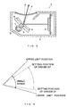
- a driver can set an angular position of the reflecting mirror 4 in an angle range (for example, 6 deg.) between an upper limit position and a lower limit position by operating a not-shown push button switch, thereby adjust a direction of the display light L projected to the windshield 1.
- the mirror can be set suit for a driver D1 having a high visual point
- the mirror can be set suit for a driver D2 having a low visual point.
- the angle range between the upper limit position and the lower limit position is shown in a magnified manner.
- the invention which was made in the light of the problem, provides display apparatus for vehicle in which the angular position of the reflecting mirror can be set in comparatively short time.
- the display apparatus for vehicles has a display device and a reflecting member, and displays a virtual image by reflecting display light emitted from the display device using the reflecting member.
- the reflecting member can be angularly moved by a driving mechanism to adjust a display position of the virtual image.
- the display apparatus for vehicles has a first operating switch for angularly moving the reflecting member upward and a second operating switch for angularly moving the reflecting member downward.
- the reflecting member When the ignition switch is turned off, the reflecting member is angularly moved to a middle position of a predetermined angle range.
- the middle position is an origin position.
- a driver adjusts the angular position of the reflecting member and then pushes a memory switch, the angular position of the reflecting member is memorized in a memory part.
- the ignition switch When the ignition switch is turned on, the reflecting member is angularly moved to the angular position memorized in the memory part.
- Fig.7 to Fig. 9 are views showing examples in the related arts; wherein Fig.7 is a view of a schematic configuration of head up display apparatus; Fig. 8 is a section view of a display unit; and Fig. 9 is an explanatory drawing of the angular movement of the reflecting mirror.
- the display unit 10 is a display unit, and the display unit 10 is arranged in a dashboard of a vehicle. Display light L projected by the display unit 10 is reflected by a windshield toward a driver. The driver of the vehicle can see a virtual image superposed with scenery.
- the liquid crystal display device 11 is a liquid crystal display device (display device), and the liquid crystal display device comprises a TFT liquid crystal display element and a backlight.
- 12 is a circuit board, and the liquid crystal display device 11 is mountedon the circuit board 12.
- 13 is a reflecting mirror (reflecting member), and the reflecting mirror 13 reflects the display light L emitted from the liquid crystal display device 11 to the windshield.
- the reflecting mirror 13 includes a reflecting face 13a formed by evaporating a metal such as aluminum on resin such as polycarbonate.
- the reflecting face 13a of the reflecting mirror 13 is a concave face, and can project the display light L from the liquid crystal display device 11 to the windshield in a magnified manner.
- the holding member 14 is a holding member, and the reflecting mirror 13 is fixed to the holding member 14 by a pressure sensitive adhesive double coated tape.
- the holding member 14 has an axis 14a, and the axis 14a is pivotally supported by a bearing provided in a housing described later.
- the reflecting mirror 13 and the holding member 14 are supported in a swingable manner, and angularly moved around the axis part 14a.
- the holding member 14 has a protrusion 14b.
- 15 is a stopper, and the stopper 15 is contacted with the protrusion 14b, thereby a movable range of the reflecting mirror 13 is limited.
- the driving mechanism 16 is a driving mechanism (driving means), and the driving mechanism 16 has a stepping motor 17, gear 18, gear 19 and cam 20.
- driving mechanism 16 uses the driving mechanism 16, the angular position of the reflecting mirror 13 is adjusted in the angle range between the upper limit position and the lower limit position.
- the gear 18 is fixed to a rotation axis of the stepping motor 17, and the gear 19 is engaged with the gear 18.
- the cam 20 is fixed to the gear 19, and rotates around an axis of the gear 19.
- the holding member 14 is pressed to the cam 20 by a not-shown coil spring, and the reflecting mirror 13 is angularly moved with the holding member 14 by rotation of the cam 20.
- the striker 21 is a striker, and the striker 21 is integrally formed with the cam 20.
- 22 is a microswitch, and the microswitch 22 is turned on by the striker 21 when the reflecting member 13 is near the origin position of the movable range. That is, the microswitch 22 detects whether the reflecting member 13 is near the origin position or not.
- the housing 23 is a housing, and the housing 23 contains the liquid crystal display device 11, circuit board 12, reflecting mirror 13, driving mechanism 16 and the like.
- 23a is a shading wall, and the shading wall 23a is integrally formed with the housing 23, and prevents a phenomenon (washout) that outside light such as sunlight is entered into the liquid crystal display device 11, causing reduction of visuality of the virtual image.
- a translucent cover 24 through which the display light L passes is arranged in the housing 23.
- the translucent cover 24, comprising translucent resin such as acrylic resin, has an arcuate shape.
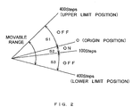
- the movable range of the reflecting mirror 13 which is appropriately established according to an area, called eye range, in which eyes of the driver are set, is about 6 deg. in this embodiment, or 800 steps in the number of steps of the stepping motor 17.
- the origin position is a center of the rotation range, and a range S1 from the origin position to the upper limit position is 400 steps, and ranges S2, S3 from the origin position to the lower limit position are 400 steps.
- the range S2 in which the microswitch 22 is turned on is 100 steps or less from the origin position to a side of the lower limit position.
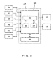
- Fig.3 is a block diagram showing an electrical configuration of the head up display apparatus.
- 25 is a velocity sensor, and the velocity sensor 25 detects velocity of the vehicle and outputs a velocity signal to a microcomputer 26.
- 27, 28 are push button switches. When the push button switches 27, 28 are turned on, a switch operating signal is outputted to the microcomputer 26, and the microcomputer 26 outputs a driving signal to the stepping motor 17 through a not-shown driver circuit, thereby rotates a rotation axis of the stepping motor 17.
- the stepping motor 17 rotates about 0.23 deg. per step, and makes one turn at 1560 steps.
- the push button 27 is turned on, the reflecting mirror 13 is angularly moved downward, and when the push button 28 is turned on, the reflecting mirror 13 is angularly moved upward.
- the memory switch 29 is a memory switch (memory operating means), and when the memory switch 29 is turned on, a switch operating signal is outputted to the microcomputer 26.
- the microcomputer 26 makes angular position data of the reflecting mirror 13 at the point be memorized in EEPROM described later. That is, when the memory switch 29 is continuously pushed for at least 0.5 sec., the angular position of the reflecting mirror 13 at the point (hereinafter, mentioned as memory position) is memorized.
- the microcomputer 26 When the memory switch 29 is turned on and then turned off in less than 0.5 sec., the microcomputer 26 outputs a driving signal to the stepping motor 18 according to the memorized angular position data. That is, when the memory switch 29 is remained on for less than 0.5 sec., the reflecting mirror 13 is angularly moved to the memorized angular position.
- the microswitch 22 detects whether the reflecting mirror 13 is near the origin position (or a position about 3 deg. upper from the lower limit position) or not.
- when the ignition switch is turned on includes not only when the ignition switch 30 is turned from ACC to ON, but also turned from OFF to ACC
- “when the ignition switch is turned off” includes not only when the ignition switch 30 is turned from ON to ACC, but also turned from ACC to OFF.
- the microcomputer 26 has CPU 32, ROM 33 and RAM 34, and performs predetermined arithmetic processing according to a velocity signal to indicate the velocity on the liquid crystal display device 11, or activates the stepping motor 18 to adjust the angle of the reflecting mirror 13.
- 36 is the EEPROM (memory part), and the EEPROM 36 stores the angular position data memorized by operating the memory switch 29. The angular position data are the number of steps from the central position to the memory position.
- a control part 37 (control means) comprises the microcomputer 26 and the EEPROM 36.
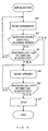
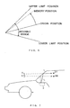
- step S1 The microcomputer 26 monitors whether the ignition switch 30 is turned on or not (step S1). When the ignition switch 30 is turned on, initialization is executed. The initialization is described later. Next, the memorized angular position data are read out from the EEPROM 36 (step S8). Next, in step S9, a driving signal is outputted to the stepping motor 18 through the driving circuit according to the read-out angular position data, thereby the reflecting mirror 13 is angularly moved to the memory position (refer to Fig.6). After processing of step S3 is completed, the microcomputer 26 performs ordinary processing such as velocity indication (step S10). When the ignition switch 30 is turned off, the microcomputer outputs a driving signal to the stepping motor 17 to return the reflecting mirror 13 to a central position as the origin position (steps S11, S12).
- step S5 When the ignition switch 30 is turned on, the microcomputer 26 outputs a driving signal to the stepping motor 17 to angularly move the reflecting mirror 13 downward (step S2).
- steps S5, S6, when the microswitch 22 is turned from on to off by angularly moving the reflecting mirror 13 upward the stepping motor 17 is stopped.
- a rotation angle of the rotation axis can be specified by giving the number of steps in correspondence with a desired rotation angle, but on the other hand, a phenomenon of step-out occurs.
- the step-out is a phenomenon that since the rotation axis of the stepping motor 17 has an infinite number of magnetically stable positions, the axis jumps over an original angular position and shifts to another stable position (for example, refer to JP-A-8-182392). Therefore, in the embodiment, when the ignition switch 30 is turned on, the reflecting mirror 13 is returned to the origin position, and even if the step-out phenomenon occurs due to some reason, the reflecting mirror 13 can be angularly moved to the memory position.
- the reflectingmirror 13 when the ignition switch 30 is turned off, the reflectingmirror 13 is returned to the central position, thereby when the vehicle is intended to be restarted, since the reflecting mirror 13 is in the central position, a period while the reflecting mirror 13 is angularly moved to the memory position can be comparatively reduced.
- the angular position to which the reflecting mirror 13 is returned can not be the central position, and for example, if it is a position upper from 2 deg. to 4 deg. from the lower limit position, the advantage that the period while the reflecting mirror 13 is angularly moved to the memory position is comparatively reduced is obtained.
- a function of memorizing the memory position may not be provided, and when the ignition switch 30 is turned off, the reflecting mirror 13 is returned to the middle position, thereby the angular position of the reflecting mirror 13 can be set in shorter time than in the related arts.
- the angular position of the reflecting mirror 13 is memorized in the EEPROM 36, thereby complexity of adjusting the angular position of the reflecting mirror 13 can be reduced.
- the ignition switch 30 is turned on, the reflecting mirror 13 is returned to the origin position, and the reflecting mirror 13 is aligned with the predetermined angular position using the number of steps from the origin position, and even if the angle sensor for detecting the angular position of the reflecting mirror 13 is not provided, the reflecting mirror 13 can be aligned with the memory position.
- the reflecting mirror 13 when the ignition switch was turned on, the reflecting mirror 13 was angularly moved to the memory position memorized using the memory switch 29. However, it is sufficient that an angular position at the time the ignition switch 30 was turned off is memorized, and when the ignition switch 30 is turned on, the reflecting mirror 13 is angularly moved to the angular position at the time the ignition switch 30 was turned off.
- the display device in the embodiment was the liquid crystal display device 11, it can be, for example, a fluorescent display tube or an organic EL display panel.
- the steppingmotor 17 was employed in the driving mechanism 16, for example, a servomotor can be employed.
- the memory part was the EEPROM 36, it can be, for example, a flash memory.
- the detecting means was the microswitch 22, it can be, for example, a photosensor.
- the embodiment while only one of the angular position data of the reflecting mirror 13 is memorized, a plural number of angular position data can be memorized in order to memorize at least two memory positions.
- the embodiment was an embodiment of the head up display, it will be obvious that the embodiment can be applied to, for example, a virtual-image-display combination meter.
- step S2 it is desired that the liquid crystal display device 11 is remained off during the initialization (step S2 to step S6) and the return to origin (step S11, step S12).
- the invention is usable for the display apparatus for vehicles, and particularly suitable for the head up display apparatus for vehicles.
Abstract
Description
- The present invention relates to display apparatus for vehicles, particularly relates to display apparatus for vehicles in which an angular position of a reflecting member for reflecting display light emitted from a display device is adjustable.
- There has been head up display apparatus that displays a virtual image V by projecting display light L from a
display unit 2 to awindshield 1 of a vehicle (refer to Fig.7). Thedisplay unit 2 has adisplay device 3 such as fluorescent display tube, reflectingmirror 4 for reflecting display light L emitted from thedisplay device 3, and steppingmotor 5 for rotating the reflectingmirror 4, which are contained in a housing 6 (refer to Fig.8). A gear 7 is mounted on a rotation axis of the steppingmotor 5, and engaged with agear part 9 fixed to a holding member 8 for holding the reflectingmirror 4. - A driver can set an angular position of the reflecting
mirror 4 in an angle range (for example, 6 deg.) between an upper limit position and a lower limit position by operating a not-shown push button switch, thereby adjust a direction of the display light L projected to thewindshield 1. For example, when the angular position of the reflectingmirror 4 is set near the lower limit position, the mirror can be set suit for a driver D1 having a high visual point, and when the angular position of the reflectingmirror 4 is set near the upper limit position, the mirror can be set suit for a driver D2 having a low visual point. To avoid complicity of the figure, in Fig. 9, the angle range between the upper limit position and the lower limit position is shown in a magnified manner. - However, there has been a problem in the case that the driver D1 finishes driving of a vehicle by turning of f an ignition switch, and at a later date, another driver D2 adjusts the angular position of the reflecting
mirror 4. That is, the angular position of the reflectingmirror 4 must be angularly moved from neighborhood of the lower limit position to neighborhood of the upper limit position, resulting in a large moving angle, therefore long time (for example, 2 sec.) is required for setting the angular position of thereflective mirror 4 by manual operation. - The invention, which was made in the light of the problem, provides display apparatus for vehicle in which the angular position of the reflecting mirror can be set in comparatively short time.
- The display apparatus for vehicles has a display device and a reflecting member, and displays a virtual image by reflecting display light emitted from the display device using the reflecting member. The reflecting member can be angularly moved by a driving mechanism to adjust a display position of the virtual image. The display apparatus for vehicles has a first operating switch for angularly moving the reflecting member upward and a second operating switch for angularly moving the reflecting member downward.
- When the ignition switch is turned off, the reflecting member is angularly moved to a middle position of a predetermined angle range. The middle position is an origin position. When a driver adjusts the angular position of the reflecting member and then pushes a memory switch, the angular position of the reflecting member is memorized in a memory part. When the ignition switch is turned on, the reflecting member is angularly moved to the angular position memorized in the memory part.
-
- Fig.1 is a section view of a display unit showing an embodiment of the invention;
- Fig.2 is an explanatory drawing of a movable range of a reflecting mirror;
- Fig.3 is a block diagram of head up display apparatus;
- Fig.4 and Fig.5 are flow charts of angular movement of the reflecting mirror; and,
- Fig.6 is an explanatory drawing of the angular movement of the reflecting mirror.
-
- Fig.7 to Fig. 9 are views showing examples in the related arts; wherein Fig.7 is a view of a schematic configuration of head up display apparatus; Fig. 8 is a section view of a display unit; and Fig. 9 is an explanatory drawing of the angular movement of the reflecting mirror.
- Hereinafter, an embodiment in which the invention is used for the head up display apparatus is described according to appended drawings.
- 10 is a display unit, and the
display unit 10 is arranged in a dashboard of a vehicle. Display light L projected by thedisplay unit 10 is reflected by a windshield toward a driver. The driver of the vehicle can see a virtual image superposed with scenery. - 11 is a liquid crystal display device (display device), and the liquid crystal display device comprises a TFT liquid crystal display element and a backlight. 12 is a circuit board, and the liquid
crystal display device 11 is mountedon thecircuit board 12. 13 is a reflecting mirror (reflecting member), and the reflectingmirror 13 reflects the display light L emitted from the liquidcrystal display device 11 to the windshield. The reflectingmirror 13 includes a reflecting face 13a formed by evaporating a metal such as aluminum on resin such as polycarbonate. The reflecting face 13a of the reflectingmirror 13 is a concave face, and can project the display light L from the liquidcrystal display device 11 to the windshield in a magnified manner. - 14 is a holding member, and the reflecting
mirror 13 is fixed to theholding member 14 by a pressure sensitive adhesive double coated tape. Theholding member 14 has anaxis 14a, and theaxis 14a is pivotally supported by a bearing provided in a housing described later. The reflectingmirror 13 and theholding member 14 are supported in a swingable manner, and angularly moved around theaxis part 14a. Theholding member 14 has a protrusion 14b. 15 is a stopper, and thestopper 15 is contacted with theprotrusion 14b, thereby a movable range of the reflectingmirror 13 is limited. - 16 is a driving mechanism (driving means), and the
driving mechanism 16 has a steppingmotor 17,gear 18,gear 19 andcam 20. Using thedriving mechanism 16, the angular position of the reflectingmirror 13 is adjusted in the angle range between the upper limit position and the lower limit position. Thegear 18 is fixed to a rotation axis of the steppingmotor 17, and thegear 19 is engaged with thegear 18. Thecam 20 is fixed to thegear 19, and rotates around an axis of thegear 19. Theholding member 14 is pressed to thecam 20 by a not-shown coil spring, and the reflectingmirror 13 is angularly moved with theholding member 14 by rotation of thecam 20. - 21 is a striker, and the
striker 21 is integrally formed with thecam 20. 22 is a microswitch, and themicroswitch 22 is turned on by thestriker 21 when the reflectingmember 13 is near the origin position of the movable range. That is, themicroswitch 22 detects whether the reflectingmember 13 is near the origin position or not. - 23 is a housing, and the
housing 23 contains the liquidcrystal display device 11,circuit board 12, reflectingmirror 13,driving mechanism 16 and the like. 23a is a shading wall, and theshading wall 23a is integrally formed with thehousing 23, and prevents a phenomenon (washout) that outside light such as sunlight is entered into the liquidcrystal display device 11, causing reduction of visuality of the virtual image. Atranslucent cover 24 through which the display light L passes is arranged in thehousing 23. Thetranslucent cover 24, comprising translucent resin such as acrylic resin, has an arcuate shape. - Next, the movable range and the like of the reflecting
mirror 13 are described according to Fig. 2. The movable range of the reflectingmirror 13, which is appropriately established according to an area, called eye range, in which eyes of the driver are set, is about 6 deg. in this embodiment, or 800 steps in the number of steps of the steppingmotor 17. The origin position is a center of the rotation range, and a range S1 from the origin position to the upper limit position is 400 steps, and ranges S2, S3 from the origin position to the lower limit position are 400 steps. The range S2 in which themicroswitch 22 is turned on is 100 steps or less from the origin position to a side of the lower limit position. - Fig.3 is a block diagram showing an electrical configuration of the head up display apparatus. 25 is a velocity sensor, and the
velocity sensor 25 detects velocity of the vehicle and outputs a velocity signal to amicrocomputer 26. 27, 28 are push button switches. When the push button switches 27, 28 are turned on, a switch operating signal is outputted to themicrocomputer 26, and themicrocomputer 26 outputs a driving signal to the steppingmotor 17 through a not-shown driver circuit, thereby rotates a rotation axis of the steppingmotor 17. The steppingmotor 17 rotates about 0.23 deg. per step, and makes one turn at 1560 steps. When thepush button 27 is turned on, the reflectingmirror 13 is angularly moved downward, and when thepush button 28 is turned on, the reflectingmirror 13 is angularly moved upward. - 29 is a memory switch (memory operating means), and when the
memory switch 29 is turned on, a switch operating signal is outputted to themicrocomputer 26. When thememory switch 29 is remained on for at least 5 seconds, themicrocomputer 26 makes angular position data of the reflectingmirror 13 at the point be memorized in EEPROM described later. That is, when thememory switch 29 is continuously pushed for at least 0.5 sec., the angular position of the reflectingmirror 13 at the point (hereinafter, mentioned as memory position) is memorized. - When the
memory switch 29 is turned on and then turned off in less than 0.5 sec., themicrocomputer 26 outputs a driving signal to the steppingmotor 18 according to the memorized angular position data. That is, when thememory switch 29 is remained on for less than 0.5 sec., the reflectingmirror 13 is angularly moved to the memorized angular position. - 30 is an ignition switch, and the
ignition switch 30 outputs an ignition state signal indicating which position of OFF, ACC, and ON the ignition is located on to themicrocomputer 26. Themicroswitch 22 detects whether the reflectingmirror 13 is near the origin position (or a position about 3 deg. upper from the lower limit position) or not. - In this specification, "when the ignition switch is turned on" includes not only when the
ignition switch 30 is turned from ACC to ON, but also turned from OFF to ACC, and "when the ignition switch is turned off" includes not only when theignition switch 30 is turned from ON to ACC, but also turned from ACC to OFF. - The
microcomputer 26 hasCPU 32,ROM 33 andRAM 34, and performs predetermined arithmetic processing according to a velocity signal to indicate the velocity on the liquidcrystal display device 11, or activates the steppingmotor 18 to adjust the angle of the reflectingmirror 13. 36 is the EEPROM (memory part), and theEEPROM 36 stores the angular position data memorized by operating thememory switch 29. The angular position data are the number of steps from the central position to the memory position. A control part 37 (control means) comprises themicrocomputer 26 and theEEPROM 36. - Next, the angular movement to the memory position is described in detail according to a flowchart shown in Fig.4. The
microcomputer 26 monitors whether theignition switch 30 is turned on or not (step S1). When theignition switch 30 is turned on, initialization is executed. The initialization is described later. Next, the memorized angular position data are read out from the EEPROM 36 (step S8). Next, in step S9, a driving signal is outputted to the steppingmotor 18 through the driving circuit according to the read-out angular position data, thereby the reflectingmirror 13 is angularly moved to the memory position (refer to Fig.6). After processing of step S3 is completed, themicrocomputer 26 performs ordinary processing such as velocity indication (step S10). When theignition switch 30 is turned off, the microcomputer outputs a driving signal to the steppingmotor 17 to return the reflectingmirror 13 to a central position as the origin position (steps S11, S12). - Next, the initialization is described in detail according to a flowchart shown in Fig.5. When the
ignition switch 30 is turned on, themicrocomputer 26 outputs a driving signal to the steppingmotor 17 to angularly move the reflectingmirror 13 downward (step S2). In steps S2, S3, when themicroswitch 22 is turned from off to on, and when themicroswitch 22 is not turned fromoff to on even if the rotation axis of the steppingmotor 17 rotates 800 steps, the initialization is advanced to step S5. Next, in steps S5, S6, when themicroswitch 22 is turned from on to off by angularly moving the reflectingmirror 13 upward, the steppingmotor 17 is stopped. - In the stepping
motor 17, there is an advantage that a rotation angle of the rotation axis can be specified by giving the number of steps in correspondence with a desired rotation angle, but on the other hand, a phenomenon of step-out occurs. The step-out is a phenomenon that since the rotation axis of the steppingmotor 17 has an infinite number of magnetically stable positions, the axis jumps over an original angular position and shifts to another stable position (for example, refer to JP-A-8-182392). Therefore, in the embodiment, when theignition switch 30 is turned on, the reflectingmirror 13 is returned to the origin position, and even if the step-out phenomenon occurs due to some reason, the reflectingmirror 13 can be angularly moved to the memory position. - In the embodiment, when the
ignition switch 30 is turned off, thereflectingmirror 13 is returned to the central position, thereby when the vehicle is intended to be restarted, since the reflectingmirror 13 is in the central position, a period while the reflectingmirror 13 is angularly moved to the memory position can be comparatively reduced. - When the
ignition switch 30 is turned off, the angular position to which the reflectingmirror 13 is returned can not be the central position, and for example, if it is a position upper from 2 deg. to 4 deg. from the lower limit position, the advantage that the period while the reflectingmirror 13 is angularly moved to the memory position is comparatively reduced is obtained. - In addition, a function of memorizing the memory position may not be provided, and when the
ignition switch 30 is turned off, the reflectingmirror 13 is returned to the middle position, thereby the angular position of the reflectingmirror 13 can be set in shorter time than in the related arts. - In the embodiment, the angular position of the reflecting
mirror 13 is memorized in theEEPROM 36, thereby complexity of adjusting the angular position of the reflectingmirror 13 can be reduced. When theignition switch 30 is turned on, the reflectingmirror 13 is returned to the origin position, and the reflectingmirror 13 is aligned with the predetermined angular position using the number of steps from the origin position, and even if the angle sensor for detecting the angular position of the reflectingmirror 13 is not provided, the reflectingmirror 13 can be aligned with the memory position. - In the embodiment, when the ignition switch was turned on, the reflecting
mirror 13 was angularly moved to the memory position memorized using thememory switch 29. However, it is sufficient that an angular position at the time theignition switch 30 was turned off is memorized, and when theignition switch 30 is turned on, the reflectingmirror 13 is angularly moved to the angular position at the time theignition switch 30 was turned off. - In addition, while the display device in the embodiment was the liquid
crystal display device 11, it can be, for example, a fluorescent display tube or an organic EL display panel. Also, while thesteppingmotor 17 was employed in thedriving mechanism 16, for example, a servomotor can be employed. Also, while the memory part was theEEPROM 36, it can be, for example, a flash memory. Also, while the detecting means was themicroswitch 22, it can be, for example, a photosensor. - Furthermore, in the embodiment, while only one of the angular position data of the reflecting
mirror 13 is memorized, a plural number of angular position data can be memorized in order to memorize at least two memory positions. In addition, while the embodiment was an embodiment of the head up display, it will be obvious that the embodiment can be applied to, for example, a virtual-image-display combination meter. - It is desired that the liquid
crystal display device 11 is remained off during the initialization (step S2 to step S6) and the return to origin (step S11, step S12). - The invention is usable for the display apparatus for vehicles, and particularly suitable for the head up display apparatus for vehicles.
Claims (11)
- Display apparatus for vehicles characterized by having a display device that emits display light, a reflecting member for reflecting the display light, driving means for angularly moving the reflecting member, and control means for angularly moving the reflecting member to a middle position of a predetermined angle range when an ignition switch is turned off.
- The display apparatus for vehicles according to claim 1 characterized by having a memory part for memorizing an angular position of the reflecting member and memory operating means for making the angular position be memorized in the memory part.
- The display apparatus for vehicles according to claim 2 characterized in that when the ignition switch is turned on, the reflecting member is angularly moved to the angular position memorized in the memory part.
- The display apparatus for vehicles according to claim 1 characterized by having a first operation switch for angularly moving the reflectingmember upward and a second operation switch for angularly moving the reflecting member downward.
- The display apparatus for vehicles according to claim 1 characterized by having detecting means for detecting the middle position of the reflecting member.
- Display apparatus for vehicles having a display device that emits display light, a reflecting member for reflecting the display light, and driving means for angularly moving the reflecting member in a predetermined angle range characterized in that a middle position of the angle range is an origin position.
- The display apparatus for vehicles according to claim 6 characterized by having control means for angularly moving the reflecting member to the origin position when an ignition switch is turned on.
- The display apparatus for vehicles according to claim 6 characterized in that a memory part for memorizing an angular position of the reflecting member and memory operating means for making the angular position be memorized in the memory part are provided.
- The display apparatus for vehicles according to claim 8 characterized in that when the ignition switch is turned on, the reflecting member is angularly moved to the origin position, and then the reflecting member is angularly moved to the angular position memorized in the memory part.
- The display apparatus for vehicles according to claim 6 characterized in that the driving means has a stepping motor.
- The display apparatus for vehicles according to claim 10 characterized in that when the ignition switch is turned on, even if the stepping motor outputs the number of steps in correspondence with the movable range and thus the reflecting member is angularly moved to one of an upside and a downside, if the detecting means does not detect that the reflecting member positions near the origin position, the control means angularly moves the reflecting member to the other of the upside and the downside, thereby the reflecting member is returned to the origin position.
Applications Claiming Priority (5)
| Application Number | Priority Date | Filing Date | Title |
|---|---|---|---|
| JP2002118972A JP2003312312A (en) | 2002-04-22 | 2002-04-22 | Display device for vehicle |
| JP2002118972 | 2002-04-22 | ||
| JP2002144356 | 2002-05-20 | ||
| JP2002144356A JP2003335148A (en) | 2002-05-20 | 2002-05-20 | Vehicular display device |
| PCT/JP2003/001828 WO2003089263A1 (en) | 2002-04-22 | 2003-02-19 | Display for vehicle |
Publications (3)
| Publication Number | Publication Date |
|---|---|
| EP1500548A1 true EP1500548A1 (en) | 2005-01-26 |
| EP1500548A4 EP1500548A4 (en) | 2005-08-10 |
| EP1500548B1 EP1500548B1 (en) | 2007-04-25 |
Family
ID=29253617
Family Applications (1)
| Application Number | Title | Priority Date | Filing Date |
|---|---|---|---|
| EP03706976A Expired - Fee Related EP1500548B1 (en) | 2002-04-22 | 2003-02-19 | Display for vehicle |
Country Status (4)
| Country | Link |
|---|---|
| US (1) | US20050162340A1 (en) |
| EP (1) | EP1500548B1 (en) |
| DE (1) | DE60313449T2 (en) |
| WO (1) | WO2003089263A1 (en) |
Cited By (5)
| Publication number | Priority date | Publication date | Assignee | Title |
|---|---|---|---|---|
| EP2515156A1 (en) * | 2009-12-18 | 2012-10-24 | Yazaki Corporation | Head-up display device |
| DE102007010381B4 (en) * | 2007-03-03 | 2015-02-05 | Audi Ag | Head-up display for a motor vehicle |
| EP3136155A4 (en) * | 2014-04-23 | 2017-11-22 | Nippon Seiki Co., Ltd. | Display device |
| WO2019068889A1 (en) * | 2017-10-05 | 2019-04-11 | Visteon Global Technologies, Inc. | Head-up display system |
| EP3521885A1 (en) * | 2018-02-01 | 2019-08-07 | Alpine Electronics, Inc. | Vehicle display device |
Families Citing this family (12)
| Publication number | Priority date | Publication date | Assignee | Title |
|---|---|---|---|---|
| JP4223942B2 (en) * | 2003-12-26 | 2009-02-12 | 矢崎総業株式会社 | Head-up display device |
| JP4309909B2 (en) * | 2006-12-01 | 2009-08-05 | 矢崎総業株式会社 | Vehicle display device and display position adjustment support method thereof |
| CN101577087B (en) * | 2009-05-26 | 2011-06-15 | 上海大峡谷光电科技有限公司 | Method for controlling LED display screen on ferris wheel and device thereof |
| JP5251853B2 (en) | 2009-12-08 | 2013-07-31 | 株式会社デンソー | Head-up display device and method for determining stepping motor driving method in head-up display device |
| JP5126323B2 (en) * | 2010-02-08 | 2013-01-23 | 株式会社デンソー | Vehicle display system and motor control device |
| JP5240222B2 (en) * | 2010-03-26 | 2013-07-17 | 株式会社デンソー | Head-up display device |
| JP5071508B2 (en) * | 2010-03-30 | 2012-11-14 | 株式会社デンソー | Head-up display device for vehicle |
| JP5799920B2 (en) * | 2012-09-07 | 2015-10-28 | 株式会社デンソー | Head-up display device for vehicle |
| DE102013213923A1 (en) | 2013-07-16 | 2015-01-22 | Johnson Controls Automotive Electronics Gmbh | Display unit for head-up display |
| JP6111940B2 (en) | 2013-09-05 | 2017-04-12 | 株式会社デンソー | Head-up display device for vehicle |
| US9964762B2 (en) * | 2015-10-07 | 2018-05-08 | E-Lead Electronic Co., Ltd. | Electric reflective plate device |
| DE102018121606A1 (en) * | 2018-09-05 | 2020-03-05 | Valeo Schalter Und Sensoren Gmbh | Swiveling mirror device for a head-up display |
Citations (5)
| Publication number | Priority date | Publication date | Assignee | Title |
|---|---|---|---|---|
| JPH0550872A (en) * | 1991-08-21 | 1993-03-02 | Nippondenso Co Ltd | Display device for vehicle |
| JPH05124457A (en) * | 1991-11-05 | 1993-05-21 | Nippondenso Co Ltd | Display device for vehicle |
| JPH0648218A (en) * | 1992-07-31 | 1994-02-22 | Isuzu Motors Ltd | Display device for vehicle |
| US5734357A (en) * | 1994-12-02 | 1998-03-31 | Fujitsu Limited | Vehicular display device adjusting to driver's positions |
| JPH11278100A (en) * | 1998-03-30 | 1999-10-12 | Nippon Seiki Kk | Display device |
Family Cites Families (7)
| Publication number | Priority date | Publication date | Assignee | Title |
|---|---|---|---|---|
| JPS6132850Y2 (en) * | 1978-12-05 | 1986-09-25 | ||
| JPS62101535A (en) * | 1985-10-28 | 1987-05-12 | Nippon Seiki Co Ltd | Information display device for automobile |
| JPS638130U (en) * | 1986-07-03 | 1988-01-20 | ||
| US4804836A (en) * | 1988-01-25 | 1989-02-14 | Yazaki Corporation | Optical apparatus having moving means for protecting an optical element for use in automatic vehicle |
| JPH0285474U (en) * | 1988-12-22 | 1990-07-04 | ||
| JP3482740B2 (en) * | 1994-06-27 | 2004-01-06 | 日産自動車株式会社 | Engine rotation detection device |
| JP2001097073A (en) * | 1999-09-28 | 2001-04-10 | Denso Corp | Head-up display for vehicle |
-
2003
- 2003-02-19 US US10/511,185 patent/US20050162340A1/en not_active Abandoned
- 2003-02-19 DE DE60313449T patent/DE60313449T2/en not_active Expired - Lifetime
- 2003-02-19 EP EP03706976A patent/EP1500548B1/en not_active Expired - Fee Related
- 2003-02-19 WO PCT/JP2003/001828 patent/WO2003089263A1/en active IP Right Grant
Patent Citations (5)
| Publication number | Priority date | Publication date | Assignee | Title |
|---|---|---|---|---|
| JPH0550872A (en) * | 1991-08-21 | 1993-03-02 | Nippondenso Co Ltd | Display device for vehicle |
| JPH05124457A (en) * | 1991-11-05 | 1993-05-21 | Nippondenso Co Ltd | Display device for vehicle |
| JPH0648218A (en) * | 1992-07-31 | 1994-02-22 | Isuzu Motors Ltd | Display device for vehicle |
| US5734357A (en) * | 1994-12-02 | 1998-03-31 | Fujitsu Limited | Vehicular display device adjusting to driver's positions |
| JPH11278100A (en) * | 1998-03-30 | 1999-10-12 | Nippon Seiki Kk | Display device |
Non-Patent Citations (4)
| Title |
|---|
| PATENT ABSTRACTS OF JAPAN vol. 017, no. 358 (M-1440), 7 July 1993 (1993-07-07) & JP 05 050872 A (NIPPONDENSO CO LTD), 2 March 1993 (1993-03-02) * |
| PATENT ABSTRACTS OF JAPAN vol. 017, no. 497 (M-1476), 8 September 1993 (1993-09-08) & JP 05 124457 A (NIPPONDENSO CO LTD), 21 May 1993 (1993-05-21) * |
| PATENT ABSTRACTS OF JAPAN vol. 2000, no. 01, 31 January 2000 (2000-01-31) & JP 11 278100 A (NIPPON SEIKI KK), 12 October 1999 (1999-10-12) * |
| See also references of WO03089263A1 * |
Cited By (7)
| Publication number | Priority date | Publication date | Assignee | Title |
|---|---|---|---|---|
| DE102007010381B4 (en) * | 2007-03-03 | 2015-02-05 | Audi Ag | Head-up display for a motor vehicle |
| EP2515156A1 (en) * | 2009-12-18 | 2012-10-24 | Yazaki Corporation | Head-up display device |
| EP2515156A4 (en) * | 2009-12-18 | 2017-05-03 | Yazaki Corporation | Head-up display device |
| EP3136155A4 (en) * | 2014-04-23 | 2017-11-22 | Nippon Seiki Co., Ltd. | Display device |
| WO2019068889A1 (en) * | 2017-10-05 | 2019-04-11 | Visteon Global Technologies, Inc. | Head-up display system |
| EP3521885A1 (en) * | 2018-02-01 | 2019-08-07 | Alpine Electronics, Inc. | Vehicle display device |
| US10782523B2 (en) | 2018-02-01 | 2020-09-22 | Alpine Electronics, Inc. | On-vehicle displays device |
Also Published As
| Publication number | Publication date |
|---|---|
| US20050162340A1 (en) | 2005-07-28 |
| WO2003089263A1 (en) | 2003-10-30 |
| DE60313449T2 (en) | 2008-01-03 |
| DE60313449D1 (en) | 2007-06-06 |
| EP1500548B1 (en) | 2007-04-25 |
| EP1500548A4 (en) | 2005-08-10 |
Similar Documents
| Publication | Publication Date | Title |
|---|---|---|
| EP1500548B1 (en) | Display for vehicle | |
| US7333269B2 (en) | Display device for vehicles | |
| US5784036A (en) | Head-up display device having selective display function for enhanced driver recognition | |
| US7764430B2 (en) | Display device for vehicle and supporting method for adjusting display position thereof | |
| KR101291408B1 (en) | Head-up display apparatus | |
| US20160320624A1 (en) | Head-up display device | |
| CN110471181B (en) | Display device for vehicle | |
| US4925272A (en) | Indication display unit for vehicles | |
| JP2005096664A (en) | Display device for vehicle | |
| JP2003039981A (en) | On-vehicle head-up display device | |
| JP2009128884A (en) | Head-up display | |
| EP3521885B1 (en) | Vehicle display device | |
| JP2009126494A (en) | Head-up display device | |
| JP2003335148A (en) | Vehicular display device | |
| KR20170008430A (en) | Head up display | |
| WO2006114950A1 (en) | On-vehicle display | |
| JPH05139186A (en) | Head-up display device for automobile | |
| JP2014202834A (en) | Head-up display device | |
| CN115047622A (en) | Display device for vehicle | |
| JP2004061861A (en) | Display device for vehicle | |
| JP2019163006A (en) | Head-up display device | |
| JPH0471729B2 (en) | ||
| CN110824705B (en) | Display device, display control method, and storage medium | |
| JP2003312312A (en) | Display device for vehicle | |
| JP2020067651A (en) | Vehicle display device |
Legal Events
| Date | Code | Title | Description |
|---|---|---|---|
| PUAI | Public reference made under article 153(3) epc to a published international application that has entered the european phase |
Free format text: ORIGINAL CODE: 0009012 |
|
| 17P | Request for examination filed |
Effective date: 20041111 |
|
| AK | Designated contracting states |
Kind code of ref document: A1 Designated state(s): AT BE BG CH CY CZ DE DK EE ES FI FR GB GR HU IE IT LI LU MC NL PT SE SI SK TR |
|
| A4 | Supplementary search report drawn up and despatched |
Effective date: 20050628 |
|
| GRAP | Despatch of communication of intention to grant a patent |
Free format text: ORIGINAL CODE: EPIDOSNIGR1 |
|
| GRAS | Grant fee paid |
Free format text: ORIGINAL CODE: EPIDOSNIGR3 |
|
| GRAA | (expected) grant |
Free format text: ORIGINAL CODE: 0009210 |
|
| AK | Designated contracting states |
Kind code of ref document: B1 Designated state(s): DE FR GB IT |
|
| REG | Reference to a national code |
Ref country code: GB Ref legal event code: FG4D |
|
| REF | Corresponds to: |
Ref document number: 60313449 Country of ref document: DE Date of ref document: 20070606 Kind code of ref document: P |
|
| ET | Fr: translation filed | ||
| PLBE | No opposition filed within time limit |
Free format text: ORIGINAL CODE: 0009261 |
|
| STAA | Information on the status of an ep patent application or granted ep patent |
Free format text: STATUS: NO OPPOSITION FILED WITHIN TIME LIMIT |
|
| 26N | No opposition filed |
Effective date: 20080128 |
|
| PGFP | Annual fee paid to national office [announced via postgrant information from national office to epo] |
Ref country code: IT Payment date: 20080227 Year of fee payment: 6 |
|
| PG25 | Lapsed in a contracting state [announced via postgrant information from national office to epo] |
Ref country code: IT Free format text: LAPSE BECAUSE OF NON-PAYMENT OF DUE FEES Effective date: 20090219 |
|
| PGFP | Annual fee paid to national office [announced via postgrant information from national office to epo] |
Ref country code: FR Payment date: 20120221 Year of fee payment: 10 |
|
| PGFP | Annual fee paid to national office [announced via postgrant information from national office to epo] |
Ref country code: DE Payment date: 20120215 Year of fee payment: 10 |
|
| PGFP | Annual fee paid to national office [announced via postgrant information from national office to epo] |
Ref country code: GB Payment date: 20120215 Year of fee payment: 10 |
|
| GBPC | Gb: european patent ceased through non-payment of renewal fee |
Effective date: 20130219 |
|
| REG | Reference to a national code |
Ref country code: FR Ref legal event code: ST Effective date: 20131031 |
|
| REG | Reference to a national code |
Ref country code: DE Ref legal event code: R119 Ref document number: 60313449 Country of ref document: DE Effective date: 20130903 |
|
| PG25 | Lapsed in a contracting state [announced via postgrant information from national office to epo] |
Ref country code: FR Free format text: LAPSE BECAUSE OF NON-PAYMENT OF DUE FEES Effective date: 20130228 Ref country code: GB Free format text: LAPSE BECAUSE OF NON-PAYMENT OF DUE FEES Effective date: 20130219 Ref country code: DE Free format text: LAPSE BECAUSE OF NON-PAYMENT OF DUE FEES Effective date: 20130903 |