EP1500545B1 - Drive force transmission equipment - Google Patents
Drive force transmission equipment Download PDFInfo
- Publication number
- EP1500545B1 EP1500545B1 EP03723169A EP03723169A EP1500545B1 EP 1500545 B1 EP1500545 B1 EP 1500545B1 EP 03723169 A EP03723169 A EP 03723169A EP 03723169 A EP03723169 A EP 03723169A EP 1500545 B1 EP1500545 B1 EP 1500545B1
- Authority
- EP
- European Patent Office
- Prior art keywords
- control device
- tight
- turning radius
- wheels
- predetermined
- Prior art date
- Legal status (The legal status is an assumption and is not a legal conclusion. Google has not performed a legal analysis and makes no representation as to the accuracy of the status listed.)
- Expired - Lifetime
Links
- 230000005540 biological transmission Effects 0.000 title claims abstract description 57
- 230000002265 prevention Effects 0.000 claims description 48
- 238000004364 calculation method Methods 0.000 claims description 29
- 230000003247 decreasing effect Effects 0.000 claims description 12
- 230000001133 acceleration Effects 0.000 claims description 8
- 230000014509 gene expression Effects 0.000 description 14
- 230000007423 decrease Effects 0.000 description 5
- 238000010276 construction Methods 0.000 description 4
- 230000035939 shock Effects 0.000 description 4
- 230000002411 adverse Effects 0.000 description 3
- 238000005516 engineering process Methods 0.000 description 3
- 230000008878 coupling Effects 0.000 description 2
- 238000010168 coupling process Methods 0.000 description 2
- 238000005859 coupling reaction Methods 0.000 description 2
- 238000004519 manufacturing process Methods 0.000 description 2
- 238000000034 method Methods 0.000 description 2
- 239000000126 substance Substances 0.000 description 1
Images


Classifications
-
- B—PERFORMING OPERATIONS; TRANSPORTING
- B60—VEHICLES IN GENERAL
- B60K—ARRANGEMENT OR MOUNTING OF PROPULSION UNITS OR OF TRANSMISSIONS IN VEHICLES; ARRANGEMENT OR MOUNTING OF PLURAL DIVERSE PRIME-MOVERS IN VEHICLES; AUXILIARY DRIVES FOR VEHICLES; INSTRUMENTATION OR DASHBOARDS FOR VEHICLES; ARRANGEMENTS IN CONNECTION WITH COOLING, AIR INTAKE, GAS EXHAUST OR FUEL SUPPLY OF PROPULSION UNITS IN VEHICLES
- B60K23/00—Arrangement or mounting of control devices for vehicle transmissions, or parts thereof, not otherwise provided for
- B60K23/08—Arrangement or mounting of control devices for vehicle transmissions, or parts thereof, not otherwise provided for for changing number of driven wheels, for switching from driving one axle to driving two or more axles
- B60K23/0808—Arrangement or mounting of control devices for vehicle transmissions, or parts thereof, not otherwise provided for for changing number of driven wheels, for switching from driving one axle to driving two or more axles for varying torque distribution between driven axles, e.g. by transfer clutch
-
- B—PERFORMING OPERATIONS; TRANSPORTING
- B60—VEHICLES IN GENERAL
- B60W—CONJOINT CONTROL OF VEHICLE SUB-UNITS OF DIFFERENT TYPE OR DIFFERENT FUNCTION; CONTROL SYSTEMS SPECIALLY ADAPTED FOR HYBRID VEHICLES; ROAD VEHICLE DRIVE CONTROL SYSTEMS FOR PURPOSES NOT RELATED TO THE CONTROL OF A PARTICULAR SUB-UNIT
- B60W2520/00—Input parameters relating to overall vehicle dynamics
- B60W2520/28—Wheel speed
-
- B—PERFORMING OPERATIONS; TRANSPORTING
- B60—VEHICLES IN GENERAL
- B60W—CONJOINT CONTROL OF VEHICLE SUB-UNITS OF DIFFERENT TYPE OR DIFFERENT FUNCTION; CONTROL SYSTEMS SPECIALLY ADAPTED FOR HYBRID VEHICLES; ROAD VEHICLE DRIVE CONTROL SYSTEMS FOR PURPOSES NOT RELATED TO THE CONTROL OF A PARTICULAR SUB-UNIT
- B60W2540/00—Input parameters relating to occupants
- B60W2540/18—Steering angle
Definitions
- the present invention relates to a control device for a drive power transmission device according to the preamble of claim 1, capable of preventing a tight-corner braking phenomenon from occurring when the turning radius is small in a four-wheel drive vehicle.
- This technology is to prevent the occurrence of the tight-corner braking phenomenon in the following way. That is, the wheel speeds of four wheels are detected by wheel speed sensors, and then, the speed difference is calculated between the outside front wheel and the inside rear wheel.
- the speed difference is equal to or larger than a judgment value which corresponds to a speed difference made on a curve with a turning radius causing the tight-corner braking to occur and when the speed difference is smaller than another judgment value which corresponds to another speed difference made on a curve with the minimum turning radius
- the motor vehicle is judged to be in a turning state with a large steering angle, so that the transmission torque of a limited differential clutch (serving as differential control device) for coupling the front and rear wheels is decreased to prevent the occurrence of the tight-corner phenomenon.
- a limited differential clutch serving as differential control device
- the causes for this are explained as follows.
- the rotational speeds of the wheels detected by the wheel speed sensors decrease to zero when the motor vehicle is stopped temporarily at the position (A), and since the judgment that the vehicle is in a turning state along a curve with a radius smaller than the tight-corner turning radius is reversed, the transmission torque of the differential control device is increased to bring the front and rear wheels into direct connection.
- the tight-corner braking phenomenon occurs to accumulate its stress in a power transmission mechanism between the front and rear wheels due to the competing rotations of the front and rear wheels depending on the difference between the traveling distances.
- the EP-A-1 127 726 discloses a control device for a drive power transmission device provided with a differential control device for distributing the transmission torque from an engine to front and rear wheels, the differential control device being capable of varying the torque distribution ratio between the front and rear wheels, wherein the control device executes a tight-corner braking prevention control under which the transmission torque of the differential control device to the front wheels or the rear wheels is decreased so as to prevent a tight-corner braking phenomenon from occurring when the turning radius of a predetermined one wheel of the wheels or the motor vehicle is equal to or smaller than a predetermined turning radius.
- the US-A-5 947 224 discloses a four-wheel drive control system for a vehicle.
- the object of the present invention is to solve the aforementioned various problems by performing a control of preventing the tight-corner braking phenomenon from occurring from the beginning of a restarting when the vehicle is restarted after being stopped temporarily in a control state that the occurrence of the tight-corner braking phenomenon is being prevented by decreasing the transmission torque of a differential control device for coupling front and rear wheels.
- the present invention resides in a drive power transmission device provided with a differential control device for distributing the transmission torque from an engine to front and rear wheels, the differential control device being capable of varying the torque distribution ratio between the front and rear wheels, and with a control device for executing a tight-corner braking prevention control under which the transmission torque of the differential control device to the front wheels or the rear wheels are decreased so as to prevent the tight-corner braking phenomenon from occurring when the turning radius of a predetermined one wheel of the wheels or the vehicle is equal to or smaller than a predetermined turning radius.
- the control device is constructed so that when the vehicle under the tight-corner braking prevention control being executed is restarted after being stopped momentarily or is accelerated from a lower vehicle speed than a predetermined vehicle speed to a higher vehicle speed than the predetermined vehicle speed, the control device executes the tight-corner braking prevention control from the beginning of the restarting or the acceleration.
- the control device since the control device is constructed so that when the vehicle under the tight-corner braking prevention control being executed is restarted after being stopped momentarily or is accelerated from a lower vehicle speed than the predetermined vehicle speed to a higher vehicle speed than the predetermined vehicle speed, the control device executes the tight-corner braking prevention control from the beginning of the restarting or the acceleration, the tight-corner braking phenomenon does not occur to give an influence on the steerability after the restarting or the commencement of the acceleration toward the predetermined vehicle speed or higher. Further, since stress is not accumulated in a power transmission mechanism between the front and rear wheels, any shock which may otherwise be given upon the release of such stress is not given.
- the present invention resides in the drive power transmission device improved as mentioned above, wherein when the vehicle is in the state that it is stopped or the vehicle speed is equal to or lower than the predetermined vehicle speed, the control device makes a tight-corner flag for determining whether to execute the tight-corner braking prevention control or not, remain in the state that the tight-corner flag was right before the stopping or right before the vehicle speed is decreased to the predetermined vehicle speed or lower.
- the control device since the control device is not required to execute any special operation but to make the tight-corner flag remain in the state that the tight-corner flag was right before the stopping or right before the vehicle speed is decreased to the predetermined vehicle speed or lower, the control device can execute accurate control in a simplified construction.
- the present invention resides in the drive power transmission device improved as mentioned above, wherein the motor vehicle is further provided with wheel speed sensors for detecting the rotational speeds of at least one pair of right and left wheels of the front and rear wheels.
- the control device executes the tight-corner braking prevention control when the turning radius of the predetermined one wheel or of the vehicle, which is calculated based on the rotational speed difference between the right and left wheels detected by the wheel speed sensors, is equal to or smaller than the predetermined turning radius.
- the turning radius of the predetermined one wheel or the vehicle is calculated based on the rotational speed difference between right and left wheels
- the slip of each wheel on the road surface causes the calculated turning radius to involve some errors. Therefore, a problem arises in that the tight-corner braking prevention control cannot be executed reliably by the use of the turning radius involving some such errors.
- the present invention resides in the drive power transmission device improved as mentioned above, wherein the motor vehicle is further provided with wheel speed sensors for respectively detecting the rotational speeds of the right and left front and rear wheels.
- the control device includes first turning radius calculation means for calculating the turning radius of the predetermined one wheel or the motor vehicle based on the rotational speed difference between either one pair of the right and left wheels of the front and rear wheels, and second turning radius calculation means for calculating the turning radius of the predetermined one wheel or the motor vehicle based on the rotational speed difference between the other pair of the right and left wheels of the front and rear wheels or based on the rotational speed difference between each one pair of the right and left wheels of the front and rear wheels.
- control device executes the tight-corner braking prevention control when the difference between the turning radiuses which are calculated respectively by the first and second turning radius calculation means is equal to or smaller than a predetermined value and when at least any one of the turning radiuses which are calculated respectively by the first and second turning radius calculation means is equal to or smaller than the predetermined turning radius.
- the drive wheels may slip because the friction coefficient ( ⁇ ) of the road surface is small.
- the execution of the tight-corner braking prevention control has caused the differential control device to distribute the drive power to the secondary drive wheels at a small transmission torque distribution rate, and therefore, it may be the case that the motor vehicle cannot be started due to the lack of the drive power at the side of the secondary drive wheels.
- the present invention resides in the drive power transmission device improved as mentioned above, wherein the control device is further provided with slip judging means for judging whether or not the drive wheels are slipping when the motor vehicle under the tight-corner braking prevention control being executed is restarted after being stopped momentarily or is accelerated from a lower vehicle speed than the predetermined speed to a higher vehicle speed than the predetermined speed. And, the control device discontinues the execution of the tight-corner braking prevention control when the slip judging means judges that the slip is occurring.
- the drive wheels may slip because the friction coefficient ( ⁇ ) of the road surface is small, in which case, the motor vehicle is returned from under the tight-corner braking prevention control to under an ordinary control, so that the transmission torque is distributed also to the secondary drive wheels to enable the vehicle to be restarted.
- the present invention resides in the drive power transmission device improved as mentioned above, wherein the slip judgment means judges that the slip is occurring when the rotational speed of any one of the drive wheels is equal to or higher than a first threshold value and when the rotational speed of any one of the secondary drive wheels is equal to or lower than a second threshold value.
- the slip judgment means judges that the slip is occurring when the rotational speed of any one of the drive wheels is equal to or higher than a first threshold value and when the rotational speed of any one of the secondary drive wheels is equal to or lower than a second threshold value.
- the drive power transmission device is composed of a differential control device 15 capable of varying the transmission torque for connecting front wheels Tf and rear wheels Tr of a motor vehicle M driven by an engine 10, and an electronic controller (control device) 20 for controlling the transmission torque of the differential control device 15.
- a differential control device 15 capable of varying the transmission torque for connecting front wheels Tf and rear wheels Tr of a motor vehicle M driven by an engine 10
- an electronic controller (control device) 20 for controlling the transmission torque of the differential control device 15.
- the drive power from the engine 10 is transmitted to a transfer 12 through a transaxle 11 incorporating a transmission therein, and at the transfer 12, the drive power distributed to the front wheel side is transmitted to right and left front wheels Tf as drive wheels through a front differential (not shown), while the drive power distributed to the rear wheel side is transmitted to right and left rear wheels Tr as secondary drive wheels through a propeller shaft 13 provided with the differential control device 15 at mid position thereof as well as through a rear differential 14.
- the differential control device 15 is a multi-plate friction clutch of electromagnetic or hydraulic type and is capable of varying the transmission torque in dependence on a control output from the electronic control device 20.
- Wheel speed sensors S1, S2, S3 and S4 for detecting the rotational speeds are provided respectively in association with right and left front wheels Tf and right and left rear wheels Tr.
- the electronic control device 20 is provided with a CPU 21 for calculating a control value of the engaging force which value is to be output to the differential control device 15 in dependence on the traveling state of the motor vehicle M, a ROM 22 having stored control programs which are necessary for such calculation and outputting, a RAM 23 used as a working area for such calculation, and an input/output circuit 24 for performing outputting and inputting to and from each of the differential control device 15 and the wheel speed sensors S1, S2, S3, S4.
- the CPU 21 of the electronic control device 20 calculates the turning radius of any of the wheels or the motor vehicle M based on the rotational speeds of the wheels Tf1, Tf2, Tr1, Tr2 which are detected by the wheel speed sensors S1, S2, S3, S4 and judges whether or not the calculated turning radius is equal to or smaller than a predetermined tight-corner turning radius.
- the CPU 21 then executes an ordinary control under which the engaging force of the differential control device 15 is increased thereby to increase the transmission torque, unless the calculated turning radius is equal to or smaller than the tight-corner turning radius, but executes a tight-corner braking prevention control under which the engaging force of the differential control device 15 is weakened thereby to decrease the transmission torque, if the calculated turning radius is equal to or smaller than the tight-corner turning radius.
- the turning radius R3 of the insider rear wheel Tr1 which is derived from the rotational speeds of the right and left rear wheels Tr and the turning radius R3' of the inside rear wheel Tr1 which is derived from the rotational speeds of the right and left front wheels Tf and the right and left rear wheels Tr.
- the reason for this will be described hereafter. It is to be noted that the turning radiuses R3 and R3' calculated herein represent those values obtained in the case that any of the wheels is not slipping.
- the two turning radiuses R 3 and R 3 ' which are calculated based on the rotational speeds of the right and left front and rear wheels Tf, Tr are those values obtained when any of the wheels Tf, Tr is not slipping on the road surface and hence, ought to become the same with each other. However, they take a smaller value than the actual turning radius when the outside front and rear wheels Tf2 and Tr2 are slipping on mud or mire, but take a larger value than the actual turning radius (or take the value obtained in the case of a reverse curve) when the inside front and rear wheels Tf1 and Tr1 are slipping on mud or mire. In either of these cases, it results that the detected turning radius includes an error.
- the two turning radiuses R 3 and R 3 ' become different values. Accordingly, by comparing the two turning radiuses R 3 and R 3 ' with each other, it becomes possible to detect whether or not the error involved in the detected turning radius R 3 has exceeded a tolerable error due to the slipping of the wheels Tf, Tr on the road surface.
- the CPU 21 of the electronic control device 20 executes the flowchart shown in Figure 3 at predetermined short time intervals.
- the CPU 21 first takes thereinto the rotational speeds ⁇ 1 , ⁇ 2 ⁇ 3 , ⁇ 4 of the right and left front and rear wheels Tf, Tr from the wheel speed sensors S1, S2, S3, S4 (step 100) and judges whether or not any of the rotational speeds ⁇ 1 , ⁇ 2 , ⁇ 3 , ⁇ 4 is zero, that is, whether or not the motor vehicle M is traveling (step 101).
- step 101 when any of the rotational speeds ⁇ 1 , ⁇ 2 , ⁇ 3 , ⁇ 4 is not zero because the motor vehicle M is traveling, the CPU 21 advances its control operation to step 102. It is to be noted that at step 101, instead of judging whether or not any of the rotational speeds ⁇ 1 , ⁇ 2 , ⁇ 3 , ⁇ 4 is zero, a judgment may be executed of whether or not all the rotational speeds ⁇ 1 , ⁇ 2 ⁇ 3 , ⁇ 4 are larger than a predetermined value ⁇ which is the slowest rotational speed detectable by the wheel speed sensors.
- the turning radius R 3 of the inside rear wheel Tr1 is calculated based on the rotational speeds ⁇ 3 , ⁇ 4 of the right and left rear wheels Tr (step 102), and it is judged whether or not the absolute value of the turning radius R 3 is equal to or smaller than a predetermined turning radius ⁇ , i.e., tight-corner turning radius (step 103).
- the CPU 21 advances its control operation to step 104, at which by the foregoing expression 6, it calculates the turning radius R 3 ' 2 of the inside rear wheel Tr1 based on the rotational speeds ⁇ 1 , ⁇ 2 , ⁇ 3 , ⁇ 4 of the right and left front and rear wheels Tf, Tr. Then, the CPU 21 advances its control operation to step 105, at which it judges whether or not the absolute value of the subtraction R 3 2 - R 3 ' 2 is equal to or smaller than another predetermined value ⁇ .
- the predetermined value ⁇ is set so that the error of the detected turning radius R 3 from the actual turning radius of the inside rear wheel Tr1 does not exceed a tolerable value. If the absolute value of the subtraction R 3 2 - R 3 ' 2 is equal to or smaller than the predetermined value ⁇ , the CPU 21 sets the tight-corner flag at step 106. Thereafter, the CPU 21 at step 110 judges whether or not the tight-corner flag has been set. In this case, since it has been set, the CPU 21 executes a tight-corner braking prevention control (step 130) as referred to later in detail and terminates the control operations according to the flowchart shown in Figure 3 .
- the CPU 21 sets the tight-corner flag and executes the tight-corner braking prevention control when the calculated turning radius R 3 is equal to or smaller than the tight-corner turning radius ⁇ and when the absolute value of the subtraction R 3 2 - R 3 ' 2 is equal to or smaller than the predetermined value ⁇ , that is, when the error of the turning radius R 3 is equal to or smaller than the tolerable value.
- the CPU 21 advances its control operation to step 107 to clear the tight-corner flag, and judges at step 110 whether or not the tight-corner flag has been set. In this case, since it has not been set, the CPU 21 executes an ordinary control (step 120) as referred to later in detail and terminates the control operations according to the flowchart shown in Figure 3 .
- the CPU 21 clears the tight-corner flag and executes the ordinary control.
- the CPU 21 skips its control operation up to step 110 without changing the state of the tight-corner flag which was held when the control cycle at that interval began to be executed, and executes the tight-corner braking prevention control (step 120) or the ordinary control (step 110) in dependence upon the state of the tight-corner flag which remains at that moment.
- the motor vehicle M is restarted after being stropped momentarily or the motor vehicle M is accelerated from the state that any of the wheel speeds is lowered than the predetermined value ⁇ .
- the drive wheels slip if the friction coefficient ( ⁇ ) of the road surface is small.
- the tight-corner flag is cleared at step 109.
- the tight-corner braking prevention control is discontinued to be returned to the ordinary control, whereby the motor vehicle M can be restarted with the secondary drive wheels being also given a sufficient transmission torque.
- the rotational speed of the outside front wheel as drive wheel becomes the maximum value ⁇ when the rotational speed of the inside rear wheel as secondary drive wheel decreases to the predetermined value ⁇ which is the lowest rotational speed detectable by the wheel speed sensor therefor.
- step 108 in order to correctly judge whether or not the slipping has occurred, the slipping is judged to have occurred when the rotational speed ⁇ 1 or ⁇ 2 of any one of the drive wheels is equal to or higher than a first threshold value which is set larger than the maximum value ⁇ and when the rotational speed ⁇ 3 or ⁇ 4 of any one of the secondary drive wheels is equal to or lower than a second threshold value which is set smaller than the predetermined value ⁇ .
- Step 108 may be changed to judge that the slipping has occurred when the rotational speed difference between the drive wheels and the secondary drive wheels exceeds a predetermined value.
- the part for executing the calculation at step 102 corresponds to the first turning radius calculation means
- the part for executing the calculation at step 104 corresponds to the second turning radius calculation means.
- the first and second turning radius calculation means may be modified to calculate the turning radiuses R 4 , R 1 , R 2 of the outside rear wheel Tr2 or the inside or outside front wheel Tf1 or Tf2, or may be modified to calculate the turning radius of the motor vehicle M itself.
- the tight-corner turning radius is set to correspond to the calculated turning radius in that case.
- the first and second turning radius calculation means may be constituted to calculate the foregoing respective turning radiuses based on the rotational speeds of the different wheels.
- the first turning radius calculation means may be constituted to calculate the turning radius based on the rotational speeds of the both front wheels Tf, while the second turning radius calculation means may be constituted to do so based on the rotational speed of the both rear wheels Tr.
- the first turning radius calculation means may be constituted to calculate the turning radius based on the rotational speeds of the both front wheels Tf and the both rear wheels Tr, while the second turning radius calculation means may be constituted to do so based on the rotational speed of the both front wheels Tf. In either case, as the slip of each wheel on the road surface increases, the difference increases between the respective turning radiuses which are calculated by the first and second turning radius calculation means.
- the CPU 21 calculates the rotational number difference between the front wheels Tf and the rear wheels Tr based on the rotational speeds of the right and left front and rear wheels Tf, Tr which are received from the wheel speed sensors S1, S2, S3, S4 (step 121) and then, calculates the vehicle speed from the average of the rotational speeds of the rear wheels Tr as the secondary drive wheels (step 122). Compensation coefficients for engaging forces each to be given to the differential control device 15 under the ordinary control have been set in correspondence to the rotational number differences as well as to the vehicle speeds and have been stored in the ROM 22 in the form of an ordinary control first map.
- a compensation coefficient for an engaging force which corresponds to a calculated rotational number difference and a calculated vehicle speed is read out from the ordinary control first map to be determined (step 123).
- the compensation coefficient in this case has been set to strengthen the engaging force in proportion to the increase in the rotational number difference in order to heighten the traction performance for enabling the vehicle to escape from a bad road such as mud, mire or the like, but has been set to weaken the engaging force in the case that the vehicle speed is high.
- the CPU 21 receives a throttle valve opening degree from a throttle valve opening degree sensor attached to a throttle valve of the engine 10 (step 124).
- Compensation coefficients for engaging forces each to be given to the differential control device 15 under the ordinary control have been set in correspondence to throttle valve opening degrees and vehicle speeds and have been stored in the ROM 22 in the form of an ordinary control second map.
- a compensation coefficient for the engaging force which corresponds to the input throttle valve opening degree and the input vehicle speed is read out from the ordinary control second map to be determined (step 125).
- the compensation coefficients for the engaging forces in this case have been set to increase the engaging force as the throttle valve opening degree becomes large with the vehicle speed being low.
- the CPU 21 determines a control value for giving the differential control device 15 an appropriate engaging force under the ordinary control and outputs the determined control value to the differential control device 15 (step 126), whereby the transmission torque of the differential control device 15 can be controlled to control the torque distribution ratio between the front wheels Tf and the rear wheels Tr.
- the CPU 21 calculates the rotational number difference between the front wheels Tf and the rear wheels Tr based on the rotational speeds of the right and left front and rear wheels Tf, Tr which are input from the wheel speed sensors S1, S2, S3, S4 (step 131), and then, calculates the vehicle speed from the average in rotational speeds of the rear wheels Tr as the secondary drive wheels (step 132). Compensation coefficients for the engaging forces to be given to the differential control device 15 under the tight-corner braking prevention control have been set in correspondence to the rotational number differences and the vehicle speeds and have been stored in the ROM 22 in the form of a tight-corner braking prevention control first map.
- a compensation coefficient for the engaging force which corresponds to the calculated rotational number difference and the calculated vehicle speed is rear out from the tight-corner braking prevention control first map to be determined (step 133).
- the compensation coefficients for this case are set to be smaller than those for the ordinary control so that the transmission torque to be transmitted to the rear wheels Tr as the secondary wheels are made small.
- the general characteristic or inclination with which the compensation coefficients are set is such that the engaging force is strengthened as the rotational number difference between the front and rear wheels increases with the vehicle speed being low, but is weakened to enhance the steerability as the vehicle speed increases, and the general inclination is the same as that for the ordinary control.
- the CPU 21 receives the throttle valve opening degree input from the throttle valve opening degree sensor which is attached to the throttle valve of the engine 10 (step 134).
- Compensation coefficients for the engaging forces to be given to the differential control device 15 under the tight-corner braking prevention control have been set in correspondence to the throttle valve opening degrees and the vehicle speeds and have been stored in the ROM 22 in the form of a tight-corner braking prevention control second map.
- a compensation coefficient for the engaging force which corresponds to the input throttle valve opening degree and the vehicle speed is rear out from the tight-corner braking prevention control second map to be determined (step 135).
- the compensation coefficients for this case are set to be smaller than those for the ordinary control.
- the general characteristic or inclination with which the compensation coefficients are set is such that the engaging force is strengthened as the throttle valve opening degree becomes large with the vehicle speed being low, and the general inclination is the same as that for the ordinary control.
- the CPU 21 determines a control value for giving the differential control device 15 an appropriate engaging force which prevents the occurrence of the tight-corner braking and outputs the determined control value to the differential control device 15 (step 136), whereby the transmission torque of the differential control device 15 can be controlled to control the torque distribution ratio between the front wheels Tf and the rear wheels Tr.
- the tight-corner flag is kept set while the tight-corner braking control is executed because the turning radius R 3 of the inside rear wheel Tr1 is equal to or smaller than the right-corner turning radius, and when the motor vehicle M is stopped or substantially stopped in this state, the tight-corner flag remains as it is without being cleared. Accordingly, when the motor vehicle M traveling along a curve W as shown in Figure 6 is stopped temporarily at a position A and then is restarted or is accelerated from the state that any of the wheel speeds is decreased to be equal to or lower than the predetermined value ⁇ , the tight-corner braking prevention control is executed to decrease the transmission torque of the differential control device 15 from right after the restarting or the acceleration.
- the drive wheels may slip because the friction coefficient ( ⁇ ) of the road surface is small.
- the tight-corner flag is cleared at step 109 if the rotational speeds of the secondary drive wheels are zero or equal to or lower than the predetermined value ⁇ .
- the tight-corner braking prevention control is discontinued to be returned to the ordinary control, and a sufficient drive torque is distributed also to the secondary drive wheels, so that the motor vehicle M can be started.
- the electronic control device 20 does nothing but to hold the tight-corner flag for determining whether to execute the tight-corner braking prevention control or not, in the state that the flag was right before the stopping, and is not needed to execute any other particular operation. Therefore, the electronic control device 20 is not complicated in construction.
- the CPU 21 of the electronic control device 20 calculates the two turning radiuses based on the rotational speeds of different wheels at step 102 and step 104 in the flowchart shown in Figure 3 , compares these turning radiuses, and executes the tight-corner braking prevention control by the use of the turning radius which is left by eliminating the other turning radius representing a larger slip and hence, a larger error as a result of such comparison. By doing so, it becomes realized that the tight-corner braking prevention control can be executed precisely.
- the present invention is not limited to this way of control and rather may be practiced in such a way as to calculate only one turning radius and to execute the tight-corner braking prevention control based on such one turning radius.
- description is directed to a four-wheel drive vehicle of the type that is not provided with any center differential.
- the present invention is applicable to a four-wheel drive vehicle of the type having such center differential, in which case the present invention may be practiced in such a form that the center differential is incorporated into, e.g., the transfer 12.
- the wheel speed sensors S1, S2, S3, S4 may be substituted by those wheel speed sensors which most of motor vehicles have for anti-skid brake systems. By doing so, the increase in the manufacturing cost for practicing the present invention becomes a little. Further, the present invention may be practiced in such a form that the substances in calculation of the first turning radius calculation means and the second turning radius calculation means in the foregoing embodiment are exchanged with each other.
- the drive power transmission device is suitable for use as a drive power transmission device for controlling the transmission torque distribution ratio between front and rear wheels through a differential control device so that the tight-corner braking phenomenon does not occur in a four-wheel drive vehicle of the type that the transmission torque from an engine is distributed to be transmitted to the front and rear wheels.
Landscapes
- Engineering & Computer Science (AREA)
- Chemical & Material Sciences (AREA)
- Combustion & Propulsion (AREA)
- Transportation (AREA)
- Mechanical Engineering (AREA)
- Arrangement And Driving Of Transmission Devices (AREA)
Abstract
Description
- The present invention relates to a control device for a drive power transmission device according to the preamble of
claim 1, capable of preventing a tight-corner braking phenomenon from occurring when the turning radius is small in a four-wheel drive vehicle. - In motor vehicles, during the traveling along a curve, the turning radiuses of front wheels become larger than those of rear wheels, so that the traveling distance of the front wheels become longer than those of the rear wheels. For this reason, in a four-wheel drive vehicle of the type that front and rear wheels are drivingly connected to be driven by an engine, a problem arises in that since the difference between the traveling distances of the front and rear wheels becomes large during the traveling along a curve with a small radius, a tight-corner braking phenomenon to act as if braking has been applied to the front wheels occurs to exert an adverse influence on the steerability. As measures to obviate the problem, there is known a technology which is disclosed in
JP-A-08-002278 - However, the foregoing technology involves the following problems. That is, as shown in
Figure 7 , when the motor vehicle M which was traveling along a curve with a turning radius equal to or smaller than a turning radius (hereafter simply as "tight-corner turning radius) which causes the tight-corner braking phenomenon to occur, is stopped temporarily at a position (A) and then is restarted, the tight-corner braking phenomenon occurs to adversely influence the steerability until the motor vehicle reaches another position (B) advanced somewhat from the stop position (A). Further, the motor vehicle suffers a shock when the tight-corner braking phenomenon is released at the position (B). - The causes for this are explained as follows. The rotational speeds of the wheels detected by the wheel speed sensors decrease to zero when the motor vehicle is stopped temporarily at the position (A), and since the judgment that the vehicle is in a turning state along a curve with a radius smaller than the tight-corner turning radius is reversed, the transmission torque of the differential control device is increased to bring the front and rear wheels into direct connection. Accordingly, by detecting the rotational speeds of the wheels by the wheel speed sensors after the restarting and then by calculating the speed difference between the outside front wheel and the inside rear wheel, it is judged that the vehicle is turning with a large steering angle to travel along a curve of a smaller radius than the tight-corner turning radius, and until so judged, the tight-corner braking phenomenon occurs to accumulate its stress in a power transmission mechanism between the front and rear wheels due to the competing rotations of the front and rear wheels depending on the difference between the traveling distances. Then, since it is judged at the position (B) that the vehicle is turning with a large steering angle along a curve of a smaller radius than the tight-corner turning radius, the transmission torque of the differential control device is decreased to release the tight-corner braking phenomenon. At this time, the stress accumulated in the power transmission mechanism is released instantaneously, so that the shock is given. This problem occurs not only when the motor vehicle M is restarted after being stopped temporarily, but also when the vehicle speed is increased again after being lowered to decrease the wheel speeds of the respective wheels to lower speeds than those which cannot be detected by the wheel speed sensors.
- The
EP-A-1 127 726 discloses a control device for a drive power transmission device provided with a differential control device for distributing the transmission torque from an engine to front and rear wheels, the differential control device being capable of varying the torque distribution ratio between the front and rear wheels, wherein the control device executes a tight-corner braking prevention control under which the transmission torque of the differential control device to the front wheels or the rear wheels is decreased so as to prevent a tight-corner braking phenomenon from occurring when the turning radius of a predetermined one wheel of the wheels or the motor vehicle is equal to or smaller than a predetermined turning radius. - The
US-A-5 947 224 discloses a four-wheel drive control system for a vehicle. - The object of the present invention is to solve the aforementioned various problems by performing a control of preventing the tight-corner braking phenomenon from occurring from the beginning of a restarting when the vehicle is restarted after being stopped temporarily in a control state that the occurrence of the tight-corner braking phenomenon is being prevented by decreasing the transmission torque of a differential control device for coupling front and rear wheels.
- The present invention resides in a drive power transmission device provided with a differential control device for distributing the transmission torque from an engine to front and rear wheels, the differential control device being capable of varying the torque distribution ratio between the front and rear wheels, and with a control device for executing a tight-corner braking prevention control under which the transmission torque of the differential control device to the front wheels or the rear wheels are decreased so as to prevent the tight-corner braking phenomenon from occurring when the turning radius of a predetermined one wheel of the wheels or the vehicle is equal to or smaller than a predetermined turning radius. The control device is constructed so that when the vehicle under the tight-corner braking prevention control being executed is restarted after being stopped momentarily or is accelerated from a lower vehicle speed than a predetermined vehicle speed to a higher vehicle speed than the predetermined vehicle speed, the control device executes the tight-corner braking prevention control from the beginning of the restarting or the acceleration.
- Therefore, according to the present invention, since the control device is constructed so that when the vehicle under the tight-corner braking prevention control being executed is restarted after being stopped momentarily or is accelerated from a lower vehicle speed than the predetermined vehicle speed to a higher vehicle speed than the predetermined vehicle speed, the control device executes the tight-corner braking prevention control from the beginning of the restarting or the acceleration, the tight-corner braking phenomenon does not occur to give an influence on the steerability after the restarting or the commencement of the acceleration toward the predetermined vehicle speed or higher. Further, since stress is not accumulated in a power transmission mechanism between the front and rear wheels, any shock which may otherwise be given upon the release of such stress is not given.
- Further, the present invention resides in the drive power transmission device improved as mentioned above, wherein when the vehicle is in the state that it is stopped or the vehicle speed is equal to or lower than the predetermined vehicle speed, the control device makes a tight-corner flag for determining whether to execute the tight-corner braking prevention control or not, remain in the state that the tight-corner flag was right before the stopping or right before the vehicle speed is decreased to the predetermined vehicle speed or lower. Thus, since the control device is not required to execute any special operation but to make the tight-corner flag remain in the state that the tight-corner flag was right before the stopping or right before the vehicle speed is decreased to the predetermined vehicle speed or lower, the control device can execute accurate control in a simplified construction.
- Furthermore, the present invention resides in the drive power transmission device improved as mentioned above, wherein the motor vehicle is further provided with wheel speed sensors for detecting the rotational speeds of at least one pair of right and left wheels of the front and rear wheels. The control device executes the tight-corner braking prevention control when the turning radius of the predetermined one wheel or of the vehicle, which is calculated based on the rotational speed difference between the right and left wheels detected by the wheel speed sensors, is equal to or smaller than the predetermined turning radius. With this configuration, since the wheel speed sensors can be substituted by those wheel sensors for antiskid brake systems as provided in most of the motor vehicles, the increase in the manufacturing cost in practicing the present invention becomes a little.
- Where the turning radius of the predetermined one wheel or the vehicle is calculated based on the rotational speed difference between right and left wheels, the slip of each wheel on the road surface causes the calculated turning radius to involve some errors. Therefore, a problem arises in that the tight-corner braking prevention control cannot be executed reliably by the use of the turning radius involving some such errors.
- In order to obviate this problem, the present invention resides in the drive power transmission device improved as mentioned above, wherein the motor vehicle is further provided with wheel speed sensors for respectively detecting the rotational speeds of the right and left front and rear wheels. The control device includes first turning radius calculation means for calculating the turning radius of the predetermined one wheel or the motor vehicle based on the rotational speed difference between either one pair of the right and left wheels of the front and rear wheels, and second turning radius calculation means for calculating the turning radius of the predetermined one wheel or the motor vehicle based on the rotational speed difference between the other pair of the right and left wheels of the front and rear wheels or based on the rotational speed difference between each one pair of the right and left wheels of the front and rear wheels. And, the control device executes the tight-corner braking prevention control when the difference between the turning radiuses which are calculated respectively by the first and second turning radius calculation means is equal to or smaller than a predetermined value and when at least any one of the turning radiuses which are calculated respectively by the first and second turning radius calculation means is equal to or smaller than the predetermined turning radius.
- With this construction, of the calculated turning radiuses, there is used one obtained when the difference between the two turning radiuses calculated by the two turning radius calculation means exceeds a predetermined value, that is, there is used one turning radius which is left by eliminating the other turning radius which is larger in the foregoing slip and hence, larger in error. Therefore, it can be realized to execute precise tight-corner braking prevention control.
- When the motor vehicle under the tight-corner braking prevention control being executed is restarted after being stopped momentarily or is accelerated from a lower vehicle speed than the predetermined speed to a higher vehicle speed than the predetermined speed, the drive wheels may slip because the friction coefficient (µ) of the road surface is small. In this case, the execution of the tight-corner braking prevention control has caused the differential control device to distribute the drive power to the secondary drive wheels at a small transmission torque distribution rate, and therefore, it may be the case that the motor vehicle cannot be started due to the lack of the drive power at the side of the secondary drive wheels.
- In order to solve this problem, the present invention resides in the drive power transmission device improved as mentioned above, wherein the control device is further provided with slip judging means for judging whether or not the drive wheels are slipping when the motor vehicle under the tight-corner braking prevention control being executed is restarted after being stopped momentarily or is accelerated from a lower vehicle speed than the predetermined speed to a higher vehicle speed than the predetermined speed. And, the control device discontinues the execution of the tight-corner braking prevention control when the slip judging means judges that the slip is occurring.
- Therefore, when the motor vehicle is restarted after being stopped momentarily or is accelerated from the state that the vehicle speed is equal to or lower than the predetermined value, the drive wheels may slip because the friction coefficient (µ) of the road surface is small, in which case, the motor vehicle is returned from under the tight-corner braking prevention control to under an ordinary control, so that the transmission torque is distributed also to the secondary drive wheels to enable the vehicle to be restarted.
- Further, the present invention resides in the drive power transmission device improved as mentioned above, wherein the slip judgment means judges that the slip is occurring when the rotational speed of any one of the drive wheels is equal to or higher than a first threshold value and when the rotational speed of any one of the secondary drive wheels is equal to or lower than a second threshold value. Thus, the occurrence of the slip can be judged correctly.
-
-
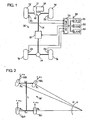
Figure 1 is an explanatory view showing the general construction of a drive power transmission device in one embodiment according to the present invention; -
Figure 2 is an explanatory view for deriving calculation expressions for turning radiuses in the embodiment shown inFigure 1 ; -
Figure 3 is a flowchart of a control program in the embodiment shown inFigure 1 ; -
Figure 4 is a flowchart of a subroutine for an ordinary control in the flowchart shown inFigure 3 ; -
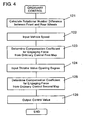
Figure 5 is a flowchart of a subroutine for a tight-corner braking prevention control in the flowchart shown inFigure 3 ; -
Figure 6 is an explanatory view illustrating the movement of a motor vehicle provided with the drive power transmission device in the embodiment shown inFigure 1 ; and -
Figure 7 is an explanatory view corresponding to that shown inFigure 6 but illustrating the movement of a motor vehicle provided with a drive power transmission device in the prior art. - Hereinafter, an embodiment of a drive power transmission device for practicing the present invention will be described with reference to the drawings. As shown mainly in
Figure 1 , the drive power transmission device according to this embodiment is composed of adifferential control device 15 capable of varying the transmission torque for connecting front wheels Tf and rear wheels Tr of a motor vehicle M driven by anengine 10, and an electronic controller (control device) 20 for controlling the transmission torque of thedifferential control device 15. The drive power from theengine 10 is transmitted to atransfer 12 through atransaxle 11 incorporating a transmission therein, and at thetransfer 12, the drive power distributed to the front wheel side is transmitted to right and left front wheels Tf as drive wheels through a front differential (not shown), while the drive power distributed to the rear wheel side is transmitted to right and left rear wheels Tr as secondary drive wheels through apropeller shaft 13 provided with thedifferential control device 15 at mid position thereof as well as through arear differential 14. Thedifferential control device 15 is a multi-plate friction clutch of electromagnetic or hydraulic type and is capable of varying the transmission torque in dependence on a control output from theelectronic control device 20. Wheel speed sensors S1, S2, S3 and S4 for detecting the rotational speeds are provided respectively in association with right and left front wheels Tf and right and left rear wheels Tr. - The
electronic control device 20 is provided with aCPU 21 for calculating a control value of the engaging force which value is to be output to thedifferential control device 15 in dependence on the traveling state of the motor vehicle M, aROM 22 having stored control programs which are necessary for such calculation and outputting, aRAM 23 used as a working area for such calculation, and an input/output circuit 24 for performing outputting and inputting to and from each of thedifferential control device 15 and the wheel speed sensors S1, S2, S3, S4. TheCPU 21 of theelectronic control device 20 calculates the turning radius of any of the wheels or the motor vehicle M based on the rotational speeds of the wheels Tf1, Tf2, Tr1, Tr2 which are detected by the wheel speed sensors S1, S2, S3, S4 and judges whether or not the calculated turning radius is equal to or smaller than a predetermined tight-corner turning radius. TheCPU 21 then executes an ordinary control under which the engaging force of thedifferential control device 15 is increased thereby to increase the transmission torque, unless the calculated turning radius is equal to or smaller than the tight-corner turning radius, but executes a tight-corner braking prevention control under which the engaging force of thedifferential control device 15 is weakened thereby to decrease the transmission torque, if the calculated turning radius is equal to or smaller than the tight-corner turning radius. - To start with, calculation expressions for calculating the turning radiuses based on the wheel rotational speeds detected by the wheel speed sensors S1, S2, S3, S4 will be explained with reference to
Figure 2 . First, various symbols are defined as follows: - L : Wheel Base
- Lf : Front Tread
- Lr : Rear Tread
- r : Radius of wheels Tf, Tr
- Ω : Turning Speed of Motor Vehicle M
- R1, ω1: Turning Radius and Rotational Speed of Inside Front Wheel Tf1
- R2, ω2: Turning Radius and Rotational Speed of Outside Front Wheel Tf2
- R3, ω3: Turning Radius and Rotational Speed of inside Rear Wheel Tr1
- R4, ω4: Turning Radius and Rotational Speed of outside Rear Wheel Tr2
- Calculated in this embodiment are the turning radius R3 of the insider rear wheel Tr1 which is derived from the rotational speeds of the right and left rear wheels Tr and the turning radius R3' of the inside rear wheel Tr1 which is derived from the rotational speeds of the right and left front wheels Tf and the right and left rear wheels Tr. The reason for this will be described hereafter. It is to be noted that the turning radiuses R3 and R3' calculated herein represent those values obtained in the case that any of the wheels is not slipping.
- Description will be made concerning the calculation procedure for the turning radius R3 of the inside rear wheel Tr1 which is based on the rotational speeds of the right and left rear wheels Tr. First, the following
expression 1 holds true between the turning speed Ω of the motor vehicle M and the rotational speed ω1, ω2, ω3, ω4 of each wheel.
- This derives the following expression 2.

- Further, the following expression 3 holds true among the turning radius R3 of the inner rear wheel Tr1, the turning radius R4 of the outside rear wheel Tr2 and the rear tread Lr.

- The following expression 4 for calculating the turning radius R3 of the inside rear wheel Tr1 can be derived from this expression 3 and the foregoing expression 2.

- Next, description will be made with respect to the calculation procedure for the turning radius R3' of the inside rear wheel Tr1 which is based on the rotational speeds of the right and left front wheels Tf and the right and left rear wheels Tr. Since the front tread Lf between the right and left front wheels Tf is approximately the same as the rear tread Lr between the right and left rear wheels Tr, the following expression 5 holds true.

- The following expression 6 for calculating the turning radius R3' of the inside rear wheel Tr1 can be derived from this expression 5 and the foregoing expression 2.

- As mentioned earlier, the two turning radiuses R3 and R3' which are calculated based on the rotational speeds of the right and left front and rear wheels Tf, Tr are those values obtained when any of the wheels Tf, Tr is not slipping on the road surface and hence, ought to become the same with each other. However, they take a smaller value than the actual turning radius when the outside front and rear wheels Tf2 and Tr2 are slipping on mud or mire, but take a larger value than the actual turning radius (or take the value obtained in the case of a reverse curve) when the inside front and rear wheels Tf1 and Tr1 are slipping on mud or mire. In either of these cases, it results that the detected turning radius includes an error. Since, with any of the wheels slipping, the slip rates of the wheels do not have the same values with one another, the two turning radiuses R3 and R3' become different values. Accordingly, by comparing the two turning radiuses R3 and R3' with each other, it becomes possible to detect whether or not the error involved in the detected turning radius R3 has exceeded a tolerable error due to the slipping of the wheels Tf, Tr on the road surface.
- Next, detecting the tight-corner braking phenomenon and controlling the engaging force of the
differential control device 15 will be described with reference to flowcharts shown inFigures 3 through 5 . TheCPU 21 of theelectronic control device 20 executes the flowchart shown inFigure 3 at predetermined short time intervals. TheCPU 21 first takes thereinto the rotational speeds ω1, ω2 ω3, ω4 of the right and left front and rear wheels Tf, Tr from the wheel speed sensors S1, S2, S3, S4 (step 100) and judges whether or not any of the rotational speeds ω1, ω2, ω3, ω4 is zero, that is, whether or not the motor vehicle M is traveling (step 101). When any of the rotational speeds ω1, ω2, ω3, ω4 is not zero because the motor vehicle M is traveling, theCPU 21 advances its control operation to step 102. It is to be noted that atstep 101, instead of judging whether or not any of the rotational speeds ω1, ω2, ω3, ω4 is zero, a judgment may be executed of whether or not all the rotational speeds ω1, ω2 ω3, ω4 are larger than a predetermined value δ which is the slowest rotational speed detectable by the wheel speed sensors. By the foregoing expression 4, the turning radius R3 of the inside rear wheel Tr1 is calculated based on the rotational speeds ω3, ω4 of the right and left rear wheels Tr (step 102), and it is judged whether or not the absolute value of the turning radius R3 is equal to or smaller than a predetermined turning radius α, i.e., tight-corner turning radius (step 103). When the turning radius R3 is equal to or smaller than the tight-corner turning radius α, theCPU 21 advances its control operation to step 104, at which by the foregoing expression 6, it calculates the turning radius R3'2 of the inside rear wheel Tr1 based on the rotational speeds ω1, ω2, ω3, ω4 of the right and left front and rear wheels Tf, Tr. Then, theCPU 21 advances its control operation to step 105, at which it judges whether or not the absolute value of the subtraction R3 2 - R3'2 is equal to or smaller than another predetermined value β. The predetermined value β is set so that the error of the detected turning radius R3 from the actual turning radius of the inside rear wheel Tr1 does not exceed a tolerable value. If the absolute value of the subtraction R3 2 - R3'2 is equal to or smaller than the predetermined value β, theCPU 21 sets the tight-corner flag atstep 106. Thereafter, theCPU 21 atstep 110 judges whether or not the tight-corner flag has been set. In this case, since it has been set, theCPU 21 executes a tight-corner braking prevention control (step 130) as referred to later in detail and terminates the control operations according to the flowchart shown inFigure 3 . As mentioned above, theCPU 21 sets the tight-corner flag and executes the tight-corner braking prevention control when the calculated turning radius R3 is equal to or smaller than the tight-corner turning radius α and when the absolute value of the subtraction R3 2 - R3'2 is equal to or smaller than the predetermined value β, that is, when the error of the turning radius R3 is equal to or smaller than the tolerable value. - When the turning radius R3 is not equal to nor smaller than the tight-corner turning radius α at
step 103, or when the absolute value of the subtraction R3 2 - R3'2 is not equal to nor smaller than the predetermined value β, theCPU 21 advances its control operation to step 107 to clear the tight-corner flag, and judges atstep 110 whether or not the tight-corner flag has been set. In this case, since it has not been set, theCPU 21 executes an ordinary control (step 120) as referred to later in detail and terminates the control operations according to the flowchart shown inFigure 3 . In short, when the calculated turning radius R3 is not equal to nor smaller than the tight-corner turning radius α, or when the error of the turning radius R3 is not equal to nor smaller than the tolerable value, theCPU 21 clears the tight-corner flag and executes the ordinary control. - When any one of the rotational speeds ω1-ω4 is judged to be zero or smaller than a predetermined value δ at
step 101 because the motor vehicle M has been stopped or substantially stopped, and when the drive wheels are judged atstep 108 to be not slipping, theCPU 21 skips its control operation up to step 110 without changing the state of the tight-corner flag which was held when the control cycle at that interval began to be executed, and executes the tight-corner braking prevention control (step 120) or the ordinary control (step 110) in dependence upon the state of the tight-corner flag which remains at that moment. Accordingly, when the motor vehicle M under the tight-corner braking prevention control being executed is restarted after being stropped momentarily or is accelerated from a lower speed than the predetermined value to a higher speed than the same, it becomes possible to execute the tight-corner braking prevention control from the beginning of the restarting or the acceleration. - In the state that the tight-corner braking prevention control is being executed, the motor vehicle M is restarted after being stropped momentarily or the motor vehicle M is accelerated from the state that any of the wheel speeds is lowered than the predetermined value δ. In either case, the drive wheels slip if the friction coefficient (µ) of the road surface is small. In this case, when it is judged at
step 101 that the rotational speeds of the secondary drive wheels are zero or smaller than the predetermined value δ, and then when it is judged atstep 108 constituting slip judging means that the drive wheels are slipping, the tight-corner flag is cleared atstep 109. Therefore, if the drive wheels slip due to the friction coefficient (µ) of the road surface being small when the vehicle is restarted after being stopped momentarily or is accelerated from the state that any of the wheel speeds is decreased to the predetermined value δ or lower, the tight-corner braking prevention control is discontinued to be returned to the ordinary control, whereby the motor vehicle M can be restarted with the secondary drive wheels being also given a sufficient transmission torque. - Where the motor vehicle M is started from the stop state as it makes turn along a curve of the minimum turning radius without slipping, the rotational speed of the outside front wheel as drive wheel becomes the maximum value γ when the rotational speed of the inside rear wheel as secondary drive wheel decreases to the predetermined value δ which is the lowest rotational speed detectable by the wheel speed sensor therefor. Therefore, at
step 108, in order to correctly judge whether or not the slipping has occurred, the slipping is judged to have occurred when the rotational speed ω1 or ω2 of any one of the drive wheels is equal to or higher than a first threshold value which is set larger than the maximum value γ and when the rotational speed ω3 or ω4 of any one of the secondary drive wheels is equal to or lower than a second threshold value which is set smaller than the predetermined value δ. Step 108 may be changed to judge that the slipping has occurred when the rotational speed difference between the drive wheels and the secondary drive wheels exceeds a predetermined value. - In a motor vehicle of the type that the drive power from the
engine 10 is directly transmitted to the right and left rear wheels Tr, but to the right and left front wheels Tf through thedifferential control device 15, the rear wheels Tr work as the drive wheels and the front wheels Tf work as the secondary drive wheels. In this case, it is judged atstep 108 that the slipping has occurred when the rotational speed ω3 or ω4 of any one of the drive wheels is equal to or higher than the first threshold value which is set larger than the maximum value γ and when the rotational speed ω1 or ω2 of any one of the secondary drive wheels is equal to or lower than the second threshold value which is set smaller than the predetermined value δ. - In connection with the claimed invention, of those control programs stored in the
ROM 22, the part for executing the calculation atstep 102 corresponds to the first turning radius calculation means, and the part for executing the calculation atstep 104 corresponds to the second turning radius calculation means. Instead of calculating the turning radius R3 of the inside rear wheel Tr1, the first and second turning radius calculation means may be modified to calculate the turning radiuses R4, R1, R2 of the outside rear wheel Tr2 or the inside or outside front wheel Tf1 or Tf2, or may be modified to calculate the turning radius of the motor vehicle M itself. In either case, the tight-corner turning radius is set to correspond to the calculated turning radius in that case. Further, the first and second turning radius calculation means may be constituted to calculate the foregoing respective turning radiuses based on the rotational speeds of the different wheels. For example, the first turning radius calculation means may be constituted to calculate the turning radius based on the rotational speeds of the both front wheels Tf, while the second turning radius calculation means may be constituted to do so based on the rotational speed of the both rear wheels Tr. Alternatively, the first turning radius calculation means may be constituted to calculate the turning radius based on the rotational speeds of the both front wheels Tf and the both rear wheels Tr, while the second turning radius calculation means may be constituted to do so based on the rotational speed of the both front wheels Tf. In either case, as the slip of each wheel on the road surface increases, the difference increases between the respective turning radiuses which are calculated by the first and second turning radius calculation means. - Next, the ordinary control at
step 120 will be described with reference to the subroutine shown inFigure 4 . In the beginning, theCPU 21 calculates the rotational number difference between the front wheels Tf and the rear wheels Tr based on the rotational speeds of the right and left front and rear wheels Tf, Tr which are received from the wheel speed sensors S1, S2, S3, S4 (step 121) and then, calculates the vehicle speed from the average of the rotational speeds of the rear wheels Tr as the secondary drive wheels (step 122). Compensation coefficients for engaging forces each to be given to thedifferential control device 15 under the ordinary control have been set in correspondence to the rotational number differences as well as to the vehicle speeds and have been stored in theROM 22 in the form of an ordinary control first map. A compensation coefficient for an engaging force which corresponds to a calculated rotational number difference and a calculated vehicle speed is read out from the ordinary control first map to be determined (step 123). In the case that the rotational number difference is large with the vehicle speed being low, it is judged that the wheels are slipping on mud, mire or the like. Therefore, the compensation coefficient in this case has been set to strengthen the engaging force in proportion to the increase in the rotational number difference in order to heighten the traction performance for enabling the vehicle to escape from a bad road such as mud, mire or the like, but has been set to weaken the engaging force in the case that the vehicle speed is high. - Subsequently, the
CPU 21 receives a throttle valve opening degree from a throttle valve opening degree sensor attached to a throttle valve of the engine 10 (step 124). Compensation coefficients for engaging forces each to be given to thedifferential control device 15 under the ordinary control have been set in correspondence to throttle valve opening degrees and vehicle speeds and have been stored in theROM 22 in the form of an ordinary control second map. A compensation coefficient for the engaging force which corresponds to the input throttle valve opening degree and the input vehicle speed is read out from the ordinary control second map to be determined (step 125). In order to heighten the starting performance and the acceleration performance, the compensation coefficients for the engaging forces in this case have been set to increase the engaging force as the throttle valve opening degree becomes large with the vehicle speed being low. Further, based on the compensation coefficient determined atsteps CPU 21 determines a control value for giving thedifferential control device 15 an appropriate engaging force under the ordinary control and outputs the determined control value to the differential control device 15 (step 126), whereby the transmission torque of thedifferential control device 15 can be controlled to control the torque distribution ratio between the front wheels Tf and the rear wheels Tr. - Next, the tight-corner braking prevention control at
step 130 will be described with reference to the subroutine shown inFigure 5 . First, theCPU 21 calculates the rotational number difference between the front wheels Tf and the rear wheels Tr based on the rotational speeds of the right and left front and rear wheels Tf, Tr which are input from the wheel speed sensors S1, S2, S3, S4 (step 131), and then, calculates the vehicle speed from the average in rotational speeds of the rear wheels Tr as the secondary drive wheels (step 132). Compensation coefficients for the engaging forces to be given to thedifferential control device 15 under the tight-corner braking prevention control have been set in correspondence to the rotational number differences and the vehicle speeds and have been stored in theROM 22 in the form of a tight-corner braking prevention control first map. Thus, a compensation coefficient for the engaging force which corresponds to the calculated rotational number difference and the calculated vehicle speed is rear out from the tight-corner braking prevention control first map to be determined (step 133). In order to prevent the tight-corner braking from occurring, the compensation coefficients for this case are set to be smaller than those for the ordinary control so that the transmission torque to be transmitted to the rear wheels Tr as the secondary wheels are made small. The general characteristic or inclination with which the compensation coefficients are set is such that the engaging force is strengthened as the rotational number difference between the front and rear wheels increases with the vehicle speed being low, but is weakened to enhance the steerability as the vehicle speed increases, and the general inclination is the same as that for the ordinary control. - Then, the
CPU 21 receives the throttle valve opening degree input from the throttle valve opening degree sensor which is attached to the throttle valve of the engine 10 (step 134). Compensation coefficients for the engaging forces to be given to thedifferential control device 15 under the tight-corner braking prevention control have been set in correspondence to the throttle valve opening degrees and the vehicle speeds and have been stored in theROM 22 in the form of a tight-corner braking prevention control second map. Thus, a compensation coefficient for the engaging force which corresponds to the input throttle valve opening degree and the vehicle speed is rear out from the tight-corner braking prevention control second map to be determined (step 135). In order to prevent the tight-corner braking from occurring, the compensation coefficients for this case are set to be smaller than those for the ordinary control. The general characteristic or inclination with which the compensation coefficients are set is such that the engaging force is strengthened as the throttle valve opening degree becomes large with the vehicle speed being low, and the general inclination is the same as that for the ordinary control. Thereafter, based on the compensation coefficients determined at the bothsteps CPU 21 determines a control value for giving thedifferential control device 15 an appropriate engaging force which prevents the occurrence of the tight-corner braking and outputs the determined control value to the differential control device 15 (step 136), whereby the transmission torque of thedifferential control device 15 can be controlled to control the torque distribution ratio between the front wheels Tf and the rear wheels Tr. - According to this embodiment, the tight-corner flag is kept set while the tight-corner braking control is executed because the turning radius R3 of the inside rear wheel Tr1 is equal to or smaller than the right-corner turning radius, and when the motor vehicle M is stopped or substantially stopped in this state, the tight-corner flag remains as it is without being cleared. Accordingly, when the motor vehicle M traveling along a curve W as shown in
Figure 6 is stopped temporarily at a position A and then is restarted or is accelerated from the state that any of the wheel speeds is decreased to be equal to or lower than the predetermined value δ, the tight-corner braking prevention control is executed to decrease the transmission torque of thedifferential control device 15 from right after the restarting or the acceleration. As a result, the tight-corner braking phenomenon does not occur after the restarting or the acceleration, so that any adverse influence is not exerted on the steerability. In addition, since no stress is accumulated in the power transmission mechanism between the front and rear wheels, it does not take place that the release of such stress gives rise to a shock. - Further, when the motor vehicle M under the tight-corner braking prevention control is stopped temporarily and then is restarted, or when the motor vehicle M under the tight-corner braking prevention control is accelerated from the state that any of the wheel speeds is decreased to the predetermined value δ or lower, the drive wheels may slip because the friction coefficient (µ) of the road surface is small. In this case, the tight-corner flag is cleared at
step 109 if the rotational speeds of the secondary drive wheels are zero or equal to or lower than the predetermined value δ. As a consequence, in the case that the drive wheels slip because the friction coefficient (µ) of the road surface is small when the motor vehicle M is stopped temporarily and then is restarted or is accelerated from the state that any of the wheel speeds is decreased to the predetermined value δ or lower, the tight-corner braking prevention control is discontinued to be returned to the ordinary control, and a sufficient drive torque is distributed also to the secondary drive wheels, so that the motor vehicle M can be started. - Also in this embodiment, when the motor vehicle M is stopped or substantially stopped as mentioned earlier, the
electronic control device 20 does nothing but to hold the tight-corner flag for determining whether to execute the tight-corner braking prevention control or not, in the state that the flag was right before the stopping, and is not needed to execute any other particular operation. Therefore, theelectronic control device 20 is not complicated in construction. - Moreover, in this embodiment, the
CPU 21 of theelectronic control device 20 calculates the two turning radiuses based on the rotational speeds of different wheels atstep 102 and step 104 in the flowchart shown inFigure 3 , compares these turning radiuses, and executes the tight-corner braking prevention control by the use of the turning radius which is left by eliminating the other turning radius representing a larger slip and hence, a larger error as a result of such comparison. By doing so, it becomes realized that the tight-corner braking prevention control can be executed precisely. However, the present invention is not limited to this way of control and rather may be practiced in such a way as to calculate only one turning radius and to execute the tight-corner braking prevention control based on such one turning radius. - Also in this embodiment, description is directed to a four-wheel drive vehicle of the type that is not provided with any center differential. However, the present invention is applicable to a four-wheel drive vehicle of the type having such center differential, in which case the present invention may be practiced in such a form that the center differential is incorporated into, e.g., the
transfer 12. - Additionally, the wheel speed sensors S1, S2, S3, S4 may be substituted by those wheel speed sensors which most of motor vehicles have for anti-skid brake systems. By doing so, the increase in the manufacturing cost for practicing the present invention becomes a little. Further, the present invention may be practiced in such a form that the substances in calculation of the first turning radius calculation means and the second turning radius calculation means in the foregoing embodiment are exchanged with each other.
- The drive power transmission device according to the present invention is suitable for use as a drive power transmission device for controlling the transmission torque distribution ratio between front and rear wheels through a differential control device so that the tight-corner braking phenomenon does not occur in a four-wheel drive vehicle of the type that the transmission torque from an engine is distributed to be transmitted to the front and rear wheels.
Claims (6)
- Control device (20) for a drive power transmission device provided with a differential control device (15) for distributing the transmission torque from an engine to front and rear wheels (Tf, Tr), the differential control device (15) being capable of varying the torque distribution ratio between the front and rear wheels (Tf, Tr), wherein the control device (20) executes a tight-corner braking prevention control under which the transmission torque of the differential control device (15) to the front wheels (Tf) or the rear wheels (Tr) is decreased so as to prevent a tight-corner braking phenomenon from occurring when the turning radius of a predetermined one wheel of the wheels (Tf, Tr) or the motor vehicle (M) is equal to or smaller than a predetermined turning radius,
characterized in that
the control device (20) is constructed so that when the motor vehicle (M) under the tight-corner braking prevention control being executed, is restarted after being stopped momentarily or is accelerated to a higher speed than a predetermined vehicle speed from a lower speed than the predetermined vehicle speed, the control device (20) executes the tight-corner braking prevention control from the beginning of the restarting or the acceleration. - Control device (20) for a drive power transmission device as set forth in Claim 1, characterized in that when the motor vehicle (M) is in the state that it is stopped or the vehicle speed is equal to or slower than the predetermined value, the control device (20) makes a tight-corner flag for determining whether to execute the tight-corner braking prevention control or not, remain in the state that the tight-corner flag was right before the stopping or right before the vehicle speed become equal to or slower than the predetermined vehicle speed.
- Control device (20) for a drive power transmission device as set forth in Claim 1 or 2, characterized in that the motor vehicle (M) is provided with wheel speed sensors (S1-S4) for detecting the rotational speeds (ω1- ω4) of at least one pair of right and left wheels of the front and rear wheels (Tf, Tr) and that the control device executes the tight-corner braking prevention control when the turning radius (R1-R4) of the predetermined one wheel or of the motor vehicle (M), which is calculated based on the rotational speed difference between the right and left wheels detected by the wheel speed sensors (S1-S4), is equal to or smaller than the predetermined turning radius.
- Control device (20) for a drive power transmission device as set forth in Claim 1 or 2, characterized in that the motor vehicle (M) is provided with wheel speed sensors (S1-S4) for respectively detecting the rotational speeds (ω1- ω4) of the right and left front and rear wheels (Tf, Tr), that the control device (20) includes first turning radius calculation means for calculating the turning radius (R1-R4) of the predetermined one wheel or the motor vehicle (M) based on the rotational speed difference between either one pair of right and left wheels of the front and rear wheels (Tf, Tr), and second turning radius calculation means for calculating the turning radius (R1-R4) of the predetermined one wheel or the motor vehicle (M) based on the rotational speed difference between the other pair of right and left wheels of the front and rear wheels (Tf, Tr) or based on the rotational speed difference between each pair of right and left wheels of the front and rear wheels (Tf, Tr), and that the control device (20) executes the tight-corner braking prevention control when the difference between the turning radiuses (R1-R4) which are calculated respectively by the first and second turning radius calculation means is equal to or smaller than a predetermined value (β) and when at least any one of the turning radiuses (R1-R4) which are calculated respectively by the first and second turning radius calculation means is equal to or smaller than the predetermined turning radius (α).
- Control device (20) for a drive power transmission device as set forth in any one of Claims 1 to 4, characterized in that the control device (20) is further provided with slip judging means for judging whether or not drive wheels are slipping when the motor vehicle (M) under the tight-corner braking prevention control being executed is restarted after being stopped momentarily or is accelerated from a lower speed than the predetermined speed to a higher speed than the predetermined speed, and that the control device (20) discontinues the execution of the tight-corner braking prevention control when the slip judging means judges that the drive wheels are slipping.
- Control device (20) for a drive power transmission device as set forth Claim 5, characterized in that the slip judging means judges that the slipping is occurring when the rotational speed of any one of the drive wheels is equal to or larger than a first threshold value and when the rotational speed of any one of secondary drive wheels is equal to or smaller than a second threshold value.
Applications Claiming Priority (3)
| Application Number | Priority Date | Filing Date | Title |
|---|---|---|---|
| JP2002126692 | 2002-04-26 | ||
| JP2002126692 | 2002-04-26 | ||
| PCT/JP2003/005134 WO2003091056A1 (en) | 2002-04-26 | 2003-04-23 | Drive force transmission equipment |
Publications (3)
| Publication Number | Publication Date |
|---|---|
| EP1500545A1 EP1500545A1 (en) | 2005-01-26 |
| EP1500545A4 EP1500545A4 (en) | 2006-05-03 |
| EP1500545B1 true EP1500545B1 (en) | 2008-04-09 |
Family
ID=29267610
Family Applications (1)
| Application Number | Title | Priority Date | Filing Date |
|---|---|---|---|
| EP03723169A Expired - Lifetime EP1500545B1 (en) | 2002-04-26 | 2003-04-23 | Drive force transmission equipment |
Country Status (5)
| Country | Link |
|---|---|
| US (1) | US7258185B2 (en) |
| EP (1) | EP1500545B1 (en) |
| JP (1) | JP4367131B2 (en) |
| DE (1) | DE60320245T2 (en) |
| WO (1) | WO2003091056A1 (en) |
Families Citing this family (13)
| Publication number | Priority date | Publication date | Assignee | Title |
|---|---|---|---|---|
| JP4223255B2 (en) * | 2002-09-24 | 2009-02-12 | 富士重工業株式会社 | Slip control device for four-wheel drive vehicles |
| US7383910B2 (en) * | 2004-03-31 | 2008-06-10 | Honda Motor Co., Ltd. | Drive force control method for four-wheel drive vehicle |
| JP5067243B2 (en) * | 2008-03-31 | 2012-11-07 | 株式会社ジェイテクト | Driving force transmission device, driving force transmission device control method, and differential limiting device |
| JP4811498B2 (en) * | 2009-05-29 | 2011-11-09 | 株式会社デンソー | Vehicle control device |
| FR2955943B1 (en) * | 2010-01-29 | 2012-06-15 | Renault Sa | SYSTEM AND METHOD FOR MONITORING THE TRACK OF A VEHICLE |
| JP5720165B2 (en) * | 2010-10-05 | 2015-05-20 | 株式会社ジェイテクト | Four-wheel drive vehicle |
| US8935080B2 (en) * | 2012-01-26 | 2015-01-13 | Ford Global Technologies, Llc | Engine response adjustment |
| CN102815211B (en) * | 2012-08-07 | 2015-02-04 | 浙江好力电动车辆制造有限公司 | Electric transport cart |
| JP5483770B2 (en) * | 2012-09-21 | 2014-05-07 | 富士重工業株式会社 | Control device for four-wheel drive vehicle |
| US9254748B2 (en) * | 2013-02-01 | 2016-02-09 | Hondata, Inc. | Vehicle traction control |
| US8918263B2 (en) | 2013-03-14 | 2014-12-23 | Clark Equipment Company | Traction control for power machine |
| AU2018224858C1 (en) | 2017-02-25 | 2021-10-28 | Pride Mobility Products Corporation | Mobility vehicle |
| CN113453438B (en) * | 2021-06-11 | 2022-10-25 | 上海美维电子有限公司 | Etching production line speed control method |
Family Cites Families (15)
| Publication number | Priority date | Publication date | Assignee | Title |
|---|---|---|---|---|
| US4702341A (en) * | 1985-12-13 | 1987-10-27 | Toyota Jidosha Kabushiki Kaisha | Four wheel drive vehicle slippage control device and method limiting center differential action according to input torque supplied thereto |
| JP2546831B2 (en) | 1987-01-19 | 1996-10-23 | アイシン・エィ・ダブリュ株式会社 | 4-wheel drive vehicle with front and rear wheel engagement mechanism |
| JPH082278A (en) | 1994-06-17 | 1996-01-09 | Nippondenso Co Ltd | Driving force control device for four-wheel drive vehicle |
| JP3409439B2 (en) * | 1994-06-17 | 2003-05-26 | 日産自動車株式会社 | Driving force distribution control system for left and right wheels and front and rear wheels |
| JP3791625B2 (en) * | 1995-08-11 | 2006-06-28 | 日産自動車株式会社 | Four-wheel drive control device for vehicle |
| JP3409537B2 (en) * | 1995-10-19 | 2003-05-26 | 日産自動車株式会社 | Vehicle four-wheel drive control device |
| JP3405052B2 (en) * | 1996-03-21 | 2003-05-12 | 日産自動車株式会社 | Driving force distribution control device |
| JP3467973B2 (en) * | 1996-06-20 | 2003-11-17 | 日産自動車株式会社 | Driving force distribution control device |
| JP3551038B2 (en) | 1998-05-08 | 2004-08-04 | 豊田工機株式会社 | Torque distribution device for four-wheel drive vehicles |
| JP3656502B2 (en) | 2000-02-28 | 2005-06-08 | 豊田工機株式会社 | Torque distribution device for four-wheel drive vehicles |
| EP1356975B1 (en) * | 2002-04-23 | 2009-12-16 | Jtekt Corporation | Torque distribution control device for four-wheel drive vehicle |
| JP3539422B2 (en) * | 2002-05-02 | 2004-07-07 | 日産自動車株式会社 | Driving force control device for four-wheel drive vehicle |
| EP1375231B1 (en) * | 2002-06-19 | 2008-10-22 | Jtekt Corporation | Drive power distribution control method and device for four-wheel drive vehicle |
| JP4120335B2 (en) * | 2002-09-26 | 2008-07-16 | 日産自動車株式会社 | Driving force distribution control device for four-wheel drive vehicle |
| JP4248838B2 (en) * | 2002-10-08 | 2009-04-02 | Gkn ドライブライン トルクテクノロジー株式会社 | Power transmission device for four-wheel drive vehicles |
-
2003
- 2003-04-23 DE DE60320245T patent/DE60320245T2/en not_active Expired - Lifetime
- 2003-04-23 JP JP2003587647A patent/JP4367131B2/en not_active Expired - Fee Related
- 2003-04-23 US US10/498,019 patent/US7258185B2/en not_active Expired - Lifetime
- 2003-04-23 WO PCT/JP2003/005134 patent/WO2003091056A1/en not_active Ceased
- 2003-04-23 EP EP03723169A patent/EP1500545B1/en not_active Expired - Lifetime
Also Published As
| Publication number | Publication date |
|---|---|
| DE60320245D1 (en) | 2008-05-21 |
| DE60320245T2 (en) | 2009-05-14 |
| WO2003091056A1 (en) | 2003-11-06 |
| EP1500545A4 (en) | 2006-05-03 |
| US20050103552A1 (en) | 2005-05-19 |
| US7258185B2 (en) | 2007-08-21 |
| JP4367131B2 (en) | 2009-11-18 |
| EP1500545A1 (en) | 2005-01-26 |
| JPWO2003091056A1 (en) | 2005-09-02 |
Similar Documents
| Publication | Publication Date | Title |
|---|---|---|
| EP0729870B1 (en) | Method for controlling yaw of a wheeled vehicle | |
| US6580994B2 (en) | Driving force controlling apparatus and method for four-wheel drive vehicle | |
| EP1500545B1 (en) | Drive force transmission equipment | |
| EP0958978B1 (en) | Vehicle yaw control method | |
| CN103260927B (en) | The driving-force control apparatus of 4Wdvehicle | |
| US6575261B2 (en) | Drive-force distribution controller | |
| EP1232900B1 (en) | Apparatus and method for controlling a four-wheel drive vehicle | |
| US6842681B2 (en) | Torque distribution control device for four-wheel drive vehicle | |
| KR101655701B1 (en) | Method for preventing damage of driving system in vehicles | |
| KR102532338B1 (en) | Steering control method for vehicles | |
| EP0416480A2 (en) | Rear wheel steering control system for vehicle | |
| EP0415451B1 (en) | Rear wheel steering control system for vehicle | |
| CN101746328B (en) | Control method for vehicle | |
| CN113428152A (en) | Vehicle control method, device and computer readable storage medium | |
| US6535809B1 (en) | Vehicle engine torque control with engine drag control mode | |
| CN114040855B (en) | Driving force distribution method and driving force distribution device for front and rear wheel drive vehicles | |
| JP4443582B2 (en) | Understeer suppression device | |
| US7290636B2 (en) | Device and method for controlling distribution of drive force of four-wheel drive car | |
| US5652383A (en) | Longitudinal grip force estimating device and slip control device for vehicle | |
| JPH05338457A (en) | 4-wheel drive system for vehicles | |
| JP3324966B2 (en) | Forward judgment device in vehicle motion control device | |
| JP3551038B2 (en) | Torque distribution device for four-wheel drive vehicles | |
| JPH06107015A (en) | Driving force distribution device for four-wheel drive vehicle | |
| JPH04332811A (en) | Detector for steering angle of automobile | |
| KR100234521B1 (en) | Control method of car traction control system |
Legal Events
| Date | Code | Title | Description |
|---|---|---|---|
| PUAI | Public reference made under article 153(3) epc to a published international application that has entered the european phase |
Free format text: ORIGINAL CODE: 0009012 |
|
| 17P | Request for examination filed |
Effective date: 20040608 |
|
| AK | Designated contracting states |
Kind code of ref document: A1 Designated state(s): AT BE BG CH CY CZ DE DK EE ES FI FR GB GR HU IE IT LI LU MC NL PT RO SE SI SK TR |
|
| A4 | Supplementary search report drawn up and despatched |
Effective date: 20060317 |
|
| RAP1 | Party data changed (applicant data changed or rights of an application transferred) |
Owner name: JTEKT CORPORATION |
|
| RIN1 | Information on inventor provided before grant (corrected) |
Inventor name: MURAKAMI, TSUYOSHI,JTEKT CORPORATION Inventor name: OHNO, AKIHIRO,JTEKT CORPORATION Inventor name: KODAMA, AKIRA,JTEKT CORPORATION |
|
| 17Q | First examination report despatched |
Effective date: 20070306 |
|
| GRAP | Despatch of communication of intention to grant a patent |
Free format text: ORIGINAL CODE: EPIDOSNIGR1 |
|
| GRAS | Grant fee paid |
Free format text: ORIGINAL CODE: EPIDOSNIGR3 |
|
| GRAA | (expected) grant |
Free format text: ORIGINAL CODE: 0009210 |
|
| AK | Designated contracting states |
Kind code of ref document: B1 Designated state(s): DE FR GB |
|
| REG | Reference to a national code |
Ref country code: GB Ref legal event code: FG4D |
|
| REF | Corresponds to: |
Ref document number: 60320245 Country of ref document: DE Date of ref document: 20080521 Kind code of ref document: P |
|
| ET | Fr: translation filed | ||
| PLBE | No opposition filed within time limit |
Free format text: ORIGINAL CODE: 0009261 |
|
| STAA | Information on the status of an ep patent application or granted ep patent |
Free format text: STATUS: NO OPPOSITION FILED WITHIN TIME LIMIT |
|
| 26N | No opposition filed |
Effective date: 20090112 |
|
| GBPC | Gb: european patent ceased through non-payment of renewal fee |
Effective date: 20080709 |
|
| PG25 | Lapsed in a contracting state [announced via postgrant information from national office to epo] |
Ref country code: GB Free format text: LAPSE BECAUSE OF NON-PAYMENT OF DUE FEES Effective date: 20080709 |
|
| REG | Reference to a national code |
Ref country code: FR Ref legal event code: PLFP Year of fee payment: 14 |
|
| REG | Reference to a national code |
Ref country code: FR Ref legal event code: PLFP Year of fee payment: 15 |
|
| REG | Reference to a national code |
Ref country code: FR Ref legal event code: PLFP Year of fee payment: 16 |
|
| PGFP | Annual fee paid to national office [announced via postgrant information from national office to epo] |
Ref country code: FR Payment date: 20210309 Year of fee payment: 19 |
|
| PGFP | Annual fee paid to national office [announced via postgrant information from national office to epo] |
Ref country code: DE Payment date: 20210330 Year of fee payment: 19 |
|
| REG | Reference to a national code |
Ref country code: DE Ref legal event code: R119 Ref document number: 60320245 Country of ref document: DE |
|
| PG25 | Lapsed in a contracting state [announced via postgrant information from national office to epo] |
Ref country code: FR Free format text: LAPSE BECAUSE OF NON-PAYMENT OF DUE FEES Effective date: 20220430 Ref country code: DE Free format text: LAPSE BECAUSE OF NON-PAYMENT OF DUE FEES Effective date: 20221103 |