EP1500327A2 - An animal stall - Google Patents
An animal stall Download PDFInfo
- Publication number
- EP1500327A2 EP1500327A2 EP04394040A EP04394040A EP1500327A2 EP 1500327 A2 EP1500327 A2 EP 1500327A2 EP 04394040 A EP04394040 A EP 04394040A EP 04394040 A EP04394040 A EP 04394040A EP 1500327 A2 EP1500327 A2 EP 1500327A2
- Authority
- EP
- European Patent Office
- Prior art keywords
- head
- head bar
- hingeing
- animal
- support frame
- Prior art date
- Legal status (The legal status is an assumption and is not a legal conclusion. Google has not performed a legal analysis and makes no representation as to the accuracy of the status listed.)
- Granted
Links
- 241001465754 Metazoa Species 0.000 title claims abstract description 63
- 230000000295 complement effect Effects 0.000 claims description 8
- 230000037431 insertion Effects 0.000 abstract 1
- 238000003780 insertion Methods 0.000 abstract 1
- 238000010276 construction Methods 0.000 description 4
- 208000027418 Wounds and injury Diseases 0.000 description 1
- 230000006378 damage Effects 0.000 description 1
- 208000014674 injury Diseases 0.000 description 1
- 238000004519 manufacturing process Methods 0.000 description 1
- 239000002184 metal Substances 0.000 description 1
Images


Classifications
-
- A—HUMAN NECESSITIES
- A01—AGRICULTURE; FORESTRY; ANIMAL HUSBANDRY; HUNTING; TRAPPING; FISHING
- A01K—ANIMAL HUSBANDRY; AVICULTURE; APICULTURE; PISCICULTURE; FISHING; REARING OR BREEDING ANIMALS, NOT OTHERWISE PROVIDED FOR; NEW BREEDS OF ANIMALS
- A01K1/00—Housing animals; Equipment therefor
- A01K1/06—Devices for fastening animals, e.g. halters, toggles, neck-bars or chain fastenings
- A01K1/0606—Devices for fastening animals, e.g. halters, toggles, neck-bars or chain fastenings by means of grids with or without movable locking bars
Definitions
- This invention relates to animal stalls.
- Various animal stall systems are available essentially comprising an upright support frame with a number of spaced-apart openings each for through passage of an animals head to feed at an opposite side of the support frame.
- the openings are defined by head bars which may be fixed or adjustable to allow an animal to insert its head through the opening which it then drops down to feed, the lower portion of the opening engaging each side of the animal's neck behind the animal's head to retain the animal in the feeding position.
- a stall of this type is disclosed in EP-A-0397257.
- a problem can arise in that an animal may slip when feeding and the neck of the animal becomes caught at the bottom of the access opening. The animal often has difficulty in retaining its feet as it is left hanging by its neck at the stall frame.
- the present invention is directed towards overcoming this problem.
- an animal stall including:
- the head bars can be moved into the fully open safety position to allow release of the animals head.
- the head bars are movable laterally relative to each other on the support frame between the normal operating position and the fully open safety position.
- the head bars are substantially parallel in the fully opened safety position.
- the head bars are movable relative to each other in a substantially upright position.
- locking means is provided for releasably securing the head bars in the normal operating position with associated actuating means operable to open the locking means to allow relative movement of the head bars to the fully open safety position.
- the locking means is a movable latch mounted on the support frame which is releasably engagable with a complementary receiver on one of said head bars which is movably mounted on the support frame.
- the latch is biased towards a receiver engaging position and a cam release means is provided which is operable to move the latch against said bias to a released position.
- the hingeing head bar is movably mounted on the support frame and other head bar is fixed on the support frame.
- the hingeing head bar is slidably mounted on the support frame.
- hingeing head bar is pivotally mounted on the support frame.
- the hingeing head bar is pivotally mounted intermediate its ends by means of a pivot point on the support frame for width adjustment of the access opening both above and below the pivot mount.
- the pivot point comprises a pivot pin which engages between the hingeing head bar and a pivot arm which is pivotally mounted on the support frame.
- the receiver of the locking means is provided on the pivot arm.
- an actuating rod is rotatably mounted on the support frame, the cam being mounted on the actuating rod and projecting outwardly therefrom for engagement with a complementary spring loaded cam follower on which the latch is mounted, a spring biasing the cam follower such that the latch is normally engaged with the complementary receiver, the actuating rod being rotatable to engage the cam with the cam follower to urge the latch into a disengaged position against spring bias.
- cam follower is slidably mounted on the support frame.
- cam follower is vertically slidable on an upright stanchion on the support frame.
- a stop is provided on the actuating rod which is engagable with a locking arm at an upper end of the hingeing head bar to prevent movement of the upper end of the hingeing head bar away from the fixed head bar, the actuating rod being rotatable for movement of the stop between engaged and released positions.
- additional stops are provided on the support frame located between an upper end of the hingeing head bar and the fixed head bar to limit movement of the upper end of the hingeing head bar towards the fixed head bar.
- the additional stops are positioned relative to the stop on the actuating rod to retain the upper end of the hingeing head bar therebetween.
- the actuating rod is rotatable between three operating positions, namely a first operating position in which the cam engages the cam follower to release the latch and the stop is disengaged to allow movement of the hingeing head bar into the fully open safety position, a second operating position In which the cam is disengaged from the cam follower and the stop is disengaged allowing pivoting of the hingeing head bar about the pivot, and a third operating position in which the cam is disengaged from the cam follower and the stop is engaged with the hingeing head bar to retain the hingeing head bar in an upright position substantially parallel to the fixed head bar.
- the stall 1 has a support frame 2 comprising a pair of spaced-apart substantially parallel rails, namely an upper rail 3 and a lower rail 4 interconnected by spaced-apart upright stanchions 5, 6.
- a pair of head bars are mounted between the rails 3, 4 and comprise a fixed head bar 7 and a hingeing head bar 8.
- An access opening 10 is defined between the head bars 7, 8 for through passage of an animals head.
- the hingeing head bar 8 is movable laterally relative to the fixed head bar 7 in the plane of the stall 1 between a normal operating position as illustrated in Fig.
- the fixed head bar 7 is secured by mounting brackets 12 to the rails 3, 4. These mounting brackets 12 clamp onto the rails 3, 4. During manufacture this allows sliding adjustment of the fixed head bar 7 along the rails 3, 4. When set in the desired position the mounting brackets 12 are tightened up on the rails 3, 4 to securely clamp the fixed head bar 7 in position. Thus the width of the access opening 10 in the normal operating position can be adjusted and set.
- the hingeing head bar 8 has a central portion 14 which extends for most of the distance between the lower rail 4 and upper rail 3.
- U-shaped slide forks are provided at each end of the central portion 14, namely an upper slide fork 15 and a lower slide fork 16.
- the upper slide fork 15 has an inner end 17 secured on the central portion 14 with a pair of outwardly extending arms 18 which as can be seen in the drawing are angled relative to the central portion 14.
- the lower slide fork 16 has an inner end 20 attached to a lower end of the central portion 14 and a pair of outwardly extending arms 21 which are angled relative to the central portion 14.
- the hingeing head bar 8 is a loose sliding fit between the rails 3, 4 for movement towards and away from the fixed head bar 7.
- the arms 18 of the upper slide fork 15 are engagable against associated stops 19 on each side of the upper rail 3 to limit movement of the hingeing head bar 8 towards the fixed head bar 7.
- a through hole 23 is provided. This is engaged by a pivot pin 24 which also engages and mounts the hingeing head bar 8 on a pivot arm 25.
- the pivot arm 25 has a pair of spaced-apart bars 26 with through holes 27 at their upper ends for engagement by the pivot pin 24 and through holes 28 at their lower ends for engagement by a pivot pin 29 to mount the pivot arm 25 at a lower end of the stanchion 6.
- the use of two bars 26 allows these bars 26 to pass on either side of the stanchion 6 in the folded position.
- a U-shaped receiver element 30 straddles the stanchion 6 having side walls 31 which extend outwardly from each of the bars 26, outer ends of the side walls 31 being interconnected by an end wall 32.
- a receiver step 34 is provided at an outer end of each side wall 31.
- the stanchion 6 is of channel section as can be seen in Fig. 10.
- a latch bar 35 which is releasably engagable in the receiver slot 34 is carried on a locking bar 36 which is slidably mounted within the stanchion 6 for vertical movement within the stanchion 6.
- the locking bar 36 is also of channel section as can be seen in Fig. 12 having side walls 37 which slide between each side of a guide member 38 located within the stanchion 6 and side walls 39 of the stanchion 6.
- the guide member 38 comprises a pair of metal blocks 33, 42 welded together and to an inner wall 41 of the stanchion 6.
- a slot 40 is provided between a rear of an outermost portion 33 of the guide 38 and the inner wall 41 of the stanchion 6 for reception of a complementary tongue 43 on the locking bar 36.
- a coil spring 44 locates in a chamber 45 formed between an inner end of the tongue 43 and a top 46 of the outermost portion 33 of the guide 38 when the tongue 43 is engaged in the slot 40 to urge the locking bar 36 upwardly engaging the latch bar 35 in the receiver slot 34 of the receiver element 30.
- a nut 50 is located within the channel of the locking bar 36. This nut 50 is engaged by a complementary bolt 51 which projects upwardly therefrom through an associated opening in the upper rail 3, a flanged head 53 of the bolt 51 projecting above the upper rail 3 as can be seen in Figs. 1 and 14.
- actuating rod 55 which is rotatably supported on mounting brackets 56 and has an actuating handle 57 at one end.
- a sleeve 60 is fixed on the actuating rod 55.
- This sleeve 60 has a cam 61 projecting outwardly therefrom.
- a movable stop 65 is also provided on the sleeve 60 which is releasably engagable with an associated locking arm 66 which extends outwardly from an upper end of the hingeing head bar 8. This stop 65 is engagable with the locking arm 66 to prevent movement of an upper end of the hingeing head bar 8. Rotation of the rod 55 by the handle 57 will release the stop 65 and allow free movement of an upper end of the hingeing head bar 8.
- a guard 70 projects laterally outwardly of the hingeing head bar 8 to prevent access by animals between the hingeing head bar 8 and the stanchion 6.
- the handle 57 has a boss 74 with three spaced-apart notches 75 which are engagable with an associated locking pin (not shown) to define three locking positions for the actuating rod 55.
- the cam 61 In a first operating position the cam 61 is engaged with the locking bar 36 releasing the locking mechanism and allowing free movement of the hingeing head bar 8 into the fully open safety position.
- the locking mechanism In a second position the locking mechanism is engaged but the stop 65 is disengaged.
- the hingeing head bar 8 is supported on the pivot arm 25 in the normal position of use in which the hingeing head bar 8 is free to pivot about the pivot pin 24 as indicated at Y in broken outline in Fig. 1 and Fig. 14 for example allowing animals to move in and out of the stall freely themselves.
- the invention provides an animal stall which allows the quick release of animals from the stall if required.
- a safety breakaway is provided for rapidly releasing the hingeing head bar 8 for movement into the fully open safety position.
- the hingeing head bar 8 can be moved to one side in an upright position to enlarge the access opening 10. It will be noted that only one stall has been described herein, however in practice normally a number of these stalls 1 will be arranged side by side in a line with common rails 3, 4 and actuating rod 55.
- a rubber bumper 80 is mounted between the bars 26 to engage with the central portion 14 of the hingeing head bar 8 when the hingeing head bar 8 is moved to the fully collapsed position alongside the stanchion 6.
- the rubber bumper 80 can be mounted by a bolt for example in one of two spaced-apart pairs of adjustment holes 81 on the bars 26.
- the stanchion 5 might form the fixed head bar.
Landscapes
- Life Sciences & Earth Sciences (AREA)
- Zoology (AREA)
- Environmental Sciences (AREA)
- Animal Husbandry (AREA)
- Biodiversity & Conservation Biology (AREA)
- Catching Or Destruction (AREA)
- Medicines Containing Material From Animals Or Micro-Organisms (AREA)
- Pharmaceuticals Containing Other Organic And Inorganic Compounds (AREA)
- Fodder In General (AREA)
Abstract
Description
- This invention relates to animal stalls.
- Various animal stall systems are available essentially comprising an upright support frame with a number of spaced-apart openings each for through passage of an animals head to feed at an opposite side of the support frame. Typically the openings are defined by head bars which may be fixed or adjustable to allow an animal to insert its head through the opening which it then drops down to feed, the lower portion of the opening engaging each side of the animal's neck behind the animal's head to retain the animal in the feeding position. A stall of this type is disclosed in EP-A-0397257. A problem can arise in that an animal may slip when feeding and the neck of the animal becomes caught at the bottom of the access opening. The animal often has difficulty in retaining its feet as it is left hanging by its neck at the stall frame. An animal has a tendency to panic in this situation and may thrash about and cause injury to itself and/or neighbouring animals in attempting to regain its feet. A pivoting head bar with a central pivot is disclosed in US 2003/0000481 which allows enlargement of a bottom portion of the opening to facilitate release of the animal's head. However, because of the construction the opening narrows upwardly which may cause difficulties by restricting movement of the animal's head through the opening.
- The present invention is directed towards overcoming this problem.
- According to the invention there is provided an animal stall, including:
- a support frame,
- a pair of spaced-apart head bars mounted on the support frame and defining therebetween and access opening for through passage of an animal's head,
- said head bars including at least one hingeing head bar pivoted intermediate it's ends about a pivot point on the support frame for hingeing about a substantially horizontal axis between a position generally parallel with the other head bar to capture an animal's head in the opening and an angled position relative to the other head bar to enlarge portion of the opening at one side of the pivot point to allow through passage of an animal's head, characterised in that means is provided for relative lateral movement between the pivot point and the other head bar between a normal operating position in which the spacing between the pivot point and the other head bar is sufficient to allow through passage of the animal's neck but not it's head and a safety position of increased spacing between the pivot point and the other head bar which allows free passage of the animal's head through the access opening.
-
- Thus advantageously if an animal is having difficulty the head bars can be moved into the fully open safety position to allow release of the animals head.
- In one embodiment the head bars are movable laterally relative to each other on the support frame between the normal operating position and the fully open safety position.
- In another embodiment the head bars are substantially parallel in the fully opened safety position.
- In a further embodiment the head bars are movable relative to each other in a substantially upright position.
- In a further embodiment locking means is provided for releasably securing the head bars in the normal operating position with associated actuating means operable to open the locking means to allow relative movement of the head bars to the fully open safety position.
- In another embodiment the locking means is a movable latch mounted on the support frame which is releasably engagable with a complementary receiver on one of said head bars which is movably mounted on the support frame.
- In another embodiment the latch is biased towards a receiver engaging position and a cam release means is provided which is operable to move the latch against said bias to a released position.
- In another embodiment the hingeing head bar is movably mounted on the support frame and other head bar is fixed on the support frame.
- In another embodiment the hingeing head bar is slidably mounted on the support frame.
- In another embodiment the hingeing head bar is pivotally mounted on the support frame.
- In a preferred embodiment the hingeing head bar is pivotally mounted intermediate its ends by means of a pivot point on the support frame for width adjustment of the access opening both above and below the pivot mount.
- In another embodiment the pivot point comprises a pivot pin which engages between the hingeing head bar and a pivot arm which is pivotally mounted on the support frame.
- In a further embodiment the receiver of the locking means is provided on the pivot arm.
- In another embodiment an actuating rod is rotatably mounted on the support frame, the cam being mounted on the actuating rod and projecting outwardly therefrom for engagement with a complementary spring loaded cam follower on which the latch is mounted, a spring biasing the cam follower such that the latch is normally engaged with the complementary receiver, the actuating rod being rotatable to engage the cam with the cam follower to urge the latch into a disengaged position against spring bias.
- In another embodiment the cam follower is slidably mounted on the support frame. Preferably the cam follower is vertically slidable on an upright stanchion on the support frame.
- In another embodiment a stop is provided on the actuating rod which is engagable with a locking arm at an upper end of the hingeing head bar to prevent movement of the upper end of the hingeing head bar away from the fixed head bar, the actuating rod being rotatable for movement of the stop between engaged and released positions.
- In another embodiment additional stops are provided on the support frame located between an upper end of the hingeing head bar and the fixed head bar to limit movement of the upper end of the hingeing head bar towards the fixed head bar. Preferably the additional stops are positioned relative to the stop on the actuating rod to retain the upper end of the hingeing head bar therebetween.
- In a further embodiment the actuating rod is rotatable between three operating positions, namely a first operating position in which the cam engages the cam follower to release the latch and the stop is disengaged to allow movement of the hingeing head bar into the fully open safety position, a second operating position In which the cam is disengaged from the cam follower and the stop is disengaged allowing pivoting of the hingeing head bar about the pivot, and a third operating position in which the cam is disengaged from the cam follower and the stop is engaged with the hingeing head bar to retain the hingeing head bar in an upright position substantially parallel to the fixed head bar.
- The invention will be more clearly understood by the following description of some embodiments thereof given by way of example only, with reference to the accompanying drawings in which:
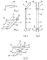
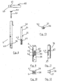
- Fig. 1 is an elevational view of an animal stall according to the invention;
- Fig. 2 is a detail end elevational view of portion of the animal stall;
- Fig. 3 is a detail end elevational view of another portion of the animal stall;
- Fig. 4 is an elevational view of a movable head bar forming portion of the stall;
- Fig. 5 is an end elevational view of the movable head bar shown in Fig. 4;
- Fig. 6 is a perspective view of a pivot arm portion of the stall;
- Fig. 7 is a detail elevational view of a receiver portion of the pivot arm shown in Fig. 6;
- Fig. 8 is an exploded, partially sectioned, elevational view showing locking means for the movable head bar;
- Fig. 9 is a detail sectional elevational view of portion of the locking means;
- Fig. 10 is a detail plan view of the locking means portion shown in Fig. 9;
- Fig. 11 is a detail sectional elevational view of an actuating rod forming portion of the locking means;
- Fig. 12 is a sectional view of the actuating rod;
- Fig. 13 is a plan view of the actuating rod; and
- Fig. 14 is an elevational view similar to Fig. 1 showing the stall in use.
- Fig. 15 is a detail view similar to Fig. 6 showing an alternative pivot arm construction.
-
- Referring to the drawings, and initially to Figs. 1 to 14 thereof, there is illustrated an animal stall according to the invention indicated generally by the reference numeral 1. The stall 1 has a support frame 2 comprising a pair of spaced-apart substantially parallel rails, namely an upper rail 3 and a
lower rail 4 interconnected by spaced-apartupright stanchions 5, 6. A pair of head bars are mounted between therails 3, 4 and comprise a fixed head bar 7 and a hingeinghead bar 8. An access opening 10 is defined between thehead bars 7, 8 for through passage of an animals head. The hingeinghead bar 8 is movable laterally relative to the fixed head bar 7 in the plane of the stall 1 between a normal operating position as illustrated in Fig. 1 which allows restricted access of the animals head through the access opening 10 and a fully open safety position as shown in broken outline in Fig. 1 and Fig. 14 indicated at X in a collapsed upright position adjacent thestanchion 6, which greatly increases the size of the access openings and allows unrestricted movement of the animals head between thehead bars 7, 8 through the access opening 10. - The fixed head bar 7 is secured by mounting
brackets 12 to therails 3, 4. Thesemounting brackets 12 clamp onto therails 3, 4. During manufacture this allows sliding adjustment of the fixed head bar 7 along therails 3, 4. When set in the desired position themounting brackets 12 are tightened up on therails 3, 4 to securely clamp the fixed head bar 7 in position. Thus the width of the access opening 10 in the normal operating position can be adjusted and set. - The hingeing
head bar 8 has acentral portion 14 which extends for most of the distance between thelower rail 4 and upper rail 3. U-shaped slide forks are provided at each end of thecentral portion 14, namely anupper slide fork 15 and alower slide fork 16. Theupper slide fork 15 has aninner end 17 secured on thecentral portion 14 with a pair of outwardly extendingarms 18 which as can be seen in the drawing are angled relative to thecentral portion 14. Similarly, thelower slide fork 16 has aninner end 20 attached to a lower end of thecentral portion 14 and a pair of outwardly extendingarms 21 which are angled relative to thecentral portion 14. It will be noted that the hingeinghead bar 8 is a loose sliding fit between therails 3, 4 for movement towards and away from the fixed head bar 7. - The
arms 18 of theupper slide fork 15 are engagable against associated stops 19 on each side of the upper rail 3 to limit movement of the hingeinghead bar 8 towards the fixed head bar 7. - Intermediate the ends of the
central portion 14, at about half way along the central portion 14 a throughhole 23 is provided. This is engaged by apivot pin 24 which also engages and mounts the hingeinghead bar 8 on apivot arm 25. Thepivot arm 25 has a pair of spaced-apart bars 26 with throughholes 27 at their upper ends for engagement by thepivot pin 24 and throughholes 28 at their lower ends for engagement by apivot pin 29 to mount thepivot arm 25 at a lower end of thestanchion 6. The use of twobars 26 allows thesebars 26 to pass on either side of thestanchion 6 in the folded position. AU-shaped receiver element 30 straddles thestanchion 6 havingside walls 31 which extend outwardly from each of thebars 26, outer ends of theside walls 31 being interconnected by anend wall 32. Areceiver step 34 is provided at an outer end of eachside wall 31. - The
stanchion 6 is of channel section as can be seen in Fig. 10. Alatch bar 35 which is releasably engagable in thereceiver slot 34 is carried on a lockingbar 36 which is slidably mounted within thestanchion 6 for vertical movement within thestanchion 6. The lockingbar 36 is also of channel section as can be seen in Fig. 12 havingside walls 37 which slide between each side of aguide member 38 located within thestanchion 6 andside walls 39 of thestanchion 6. Theguide member 38 comprises a pair of metal blocks 33, 42 welded together and to aninner wall 41 of thestanchion 6. Aslot 40 is provided between a rear of anoutermost portion 33 of theguide 38 and theinner wall 41 of thestanchion 6 for reception of acomplementary tongue 43 on the lockingbar 36. Acoil spring 44 locates in achamber 45 formed between an inner end of thetongue 43 and a top 46 of theoutermost portion 33 of theguide 38 when thetongue 43 is engaged in theslot 40 to urge the lockingbar 36 upwardly engaging thelatch bar 35 in thereceiver slot 34 of thereceiver element 30. - At an upper end of the locking bar 36 a
nut 50 is located within the channel of the lockingbar 36. Thisnut 50 is engaged by acomplementary bolt 51 which projects upwardly therefrom through an associated opening in the upper rail 3, aflanged head 53 of thebolt 51 projecting above the upper rail 3 as can be seen in Figs. 1 and 14. - Mounted on the upper rail 3, and extending substantially parallel thereto, is an actuating
rod 55 which is rotatably supported on mountingbrackets 56 and has anactuating handle 57 at one end. Asleeve 60 is fixed on theactuating rod 55. Thissleeve 60 has acam 61 projecting outwardly therefrom. Thus when the actuatingrod 55 is rotated thecam 61 engages theflanged head 53 of thebolt 51 urging the lockingbar 36 downwardly against spring bias to release thelatch bar 35 from thereceiver 34. This in turn will allow thepivot arm 25 to pivot in the direction of arrow A (Fig. 1) which allows movement of the hingeinghead bar 8 away from the fixed head bar 7 into a fully open safety position adjacent thestanchion 6 as indicated in broken outline at X in Fig. 1 and Fig. 14. Effectively then thebolt 51 and lockingbar 36 form a spring loaded cam follower operable for release of thelatch bar 35 from thereceiver element 30. - A
movable stop 65 is also provided on thesleeve 60 which is releasably engagable with an associated lockingarm 66 which extends outwardly from an upper end of the hingeinghead bar 8. Thisstop 65 is engagable with the lockingarm 66 to prevent movement of an upper end of the hingeinghead bar 8. Rotation of therod 55 by thehandle 57 will release thestop 65 and allow free movement of an upper end of the hingeinghead bar 8. - A
guard 70 projects laterally outwardly of the hingeinghead bar 8 to prevent access by animals between the hingeinghead bar 8 and thestanchion 6. - The
handle 57 has aboss 74 with three spaced-apartnotches 75 which are engagable with an associated locking pin (not shown) to define three locking positions for theactuating rod 55. In a first operating position thecam 61 is engaged with the lockingbar 36 releasing the locking mechanism and allowing free movement of the hingeinghead bar 8 into the fully open safety position. In a second position the locking mechanism is engaged but thestop 65 is disengaged. In this position the hingeinghead bar 8 is supported on thepivot arm 25 in the normal position of use in which thehingeing head bar 8 is free to pivot about thepivot pin 24 as indicated at Y in broken outline in Fig. 1 and Fig. 14 for example allowing animals to move in and out of the stall freely themselves. In the third position thestop 65 is engaged locking the hingeinghead bar 8 in the upright position shown in Fig. 1 substantially parallel to the fixed head bar 7 and in this position access is denied to the animal through the access opening 10 or if the animal already has its head through the access opening 10 then the head of the animal is caught in the access opening 10. - It will be appreciated that the invention provides an animal stall which allows the quick release of animals from the stall if required. A safety breakaway is provided for rapidly releasing the hingeing
head bar 8 for movement into the fully open safety position. The hingeinghead bar 8 can be moved to one side in an upright position to enlarge the access opening 10. It will be noted that only one stall has been described herein, however in practice normally a number of these stalls 1 will be arranged side by side in a line withcommon rails 3, 4 and actuatingrod 55. - Referring now to Fig. 15 there is shown an alternative construction of
pivot arm 25. Parts similar to those described previously are assigned the same reference numerals. In this case arubber bumper 80 is mounted between thebars 26 to engage with thecentral portion 14 of the hingeinghead bar 8 when the hingeinghead bar 8 is moved to the fully collapsed position alongside thestanchion 6. Therubber bumper 80 can be mounted by a bolt for example in one of two spaced-apart pairs of adjustment holes 81 on thebars 26. - It will also be noted that the
lower slide fork 16 on thehingeing head bar 8 may be omitted in an alternative embodiment. - It is envisaged that in some cases the stanchion 5 might form the fixed head bar.
- The invention is not limited to the embodiments hereinbefore described which may be varied in both construction and detail within the scope of the appended claims.
Claims (16)
- An animal stall (1), including:characterised in that means (25, 30, 35, 36) is provided for relative movement between the pivot point (24) and the other head bar (7) between a normal operating position in which the spacing between the pivot point (24) and the other head bar (7) is sufficient to allow through passage of the animal's neck but not it's head and a safety position of increased spacing between the pivot point (24) and the other head bar (7) which allows free passage of the animal's head through the access opening (10).a support frame (2),a pair of spaced-apart head bars (7, 8) mounted on the support frame (2) and defining therebetween an access opening (10) for through passage of an animal's head,said head bars (7, 8) including at least one hingeing head bar (8) pivoted intermediate its ends about a pivot point (24) on the support frame (2) for hingeing about a substantially horizontal axis between a position generally parallel with the other head bar (7) to capture an animal's head in the opening (10) and an angled position relative to the other head bar to enlarge portion of the opening (10) at one side of the pivot point (24) to allow through passage of an animal's head,
- An animal stall (1) as claimed in claim 1 wherein the head bars (7, 8) are movable laterally relative to each other on the support frame (2) between the normal operating position and the fully open safety position.
- An animal stall (1) as claimed in claim 1 or claim 2 wherein the head bars (7, 8) are substantially parallel in the fully open safety position.
- An animal stall (1) as claimed in any preceding claim wherein the head bars (7, 8) are movable relative to each other in a substantially upright position.
- An animal stall (1) as claimed in any preceding claim wherein locking means (30, 35) is provided for releasably securing the head bars (7, 8) in the normal operating position with associated actuating means (60, 61, 36) operable to open the locking means (30, 35) to allow relative movement of the head bars (7, 8) to the fully open safety position.
- An animal stall (1) as claimed in claim 5 wherein the locking means is a movable latch (35) mounted on the support frame (2) which is releasably engagable with a complementary receiver (30) on one of said head bars (8) which is movably mounted on the support frame (2).
- An animal stall (1) as claimed in claim 6 wherein the latch (35) is biased towards a receiver (30) engaging position and a cam (61) release means is provided which is operable to move the latch (35) against said bias to a released position.
- An animal stall (1) as claimed in any preceding claim wherein the hingeing head bar (8) is movably mounted on the support frame (2) and the other head bar (7) is fixed on the support frame (2).
- An animal stall (1) as claimed in claim 8 wherein the hingeing head bar (8) is slidably mounted on the support frame (2).
- An animal stall (1) as claimed in claim 8 or 9 wherein the hingeing head bar (8) is pivotally mounted on the support frame (2).
- An animal stall (1) as claimed in any preceding claim wherein the pivot point (24) for the hingeing head bar (8) comprises a pivot pin (24) which engages between the hingeing head bar (8) and a pivot arm (25) which is pivotally mounted on the support frame (2), for pivoting about a substantially horizontal axis.
- An animal stall (1) as claimed in claim 11 wherein the receiver (30) of the locking means is provided on the pivot arm (25).
- An animal stall (1) as claimed in any preceding claim wherein an actuating rod (55) is rotatably mounted on the support frame, the cam (61) being mounted on the actuating rod (55) and projecting outwardly therefrom for engagement with a complementary spring loaded cam follower (53, 36) on which the latch (35) is mounted, a spring (44) biasing the cam follower (53, 36) such that the latch (35) is normally engaged with the complementary receiver (30), the actuating rod (55) being rotatable to engage the cam (61) with the cam follower (53, 36) to urge the latch (35) into a disengaged position against spring (44) bias.
- An animal stall (1) as claimed in claim 13 wherein a stop (65) is provided on the actuating rod (55) which is engagable with a locking arm (66) at an upper end of the hingeing head bar (8) to prevent movement of the upper end of the hingeing head bar (8) away from the fixed head bar (7), the actuating rod (5) being rotatable for movement of the stop (65) between engaged and release positions.
- An animal stall (1) as claimed in any preceding claim wherein additional stops (19) are provided on the support frame (2) located between an upper end (18) of the hingeing head bar (8) and the fixed head bar (7) to limit movement of the upper end (18) of the hingeing head bar (8) towards the fixed head bar (7).
- An animal stall (1) as claimed in any of claims 13 to 15 wherein the actuating rod (55) is rotatable between the three operating positions, namely a first operating position in which the cam (61) engages the cam follower (53, 36) to release the latch (35) and the stop (65) is disengaged to allow movement of the hingeing head bar (8) into the fully open safety position, a second operating position in which the cam (61) is disengaged from the cam follower (53, 36) and the stop (65) is disengaged allowing pivoting of the hingeing head bar (8) about the pivot point (24), and a third operating position in which the cam (61) is disengaged from the cam follower (53, 36) and the stop (65) is engaged with the hingeing head bar (8) to retain the hingeing head bar (8) in an upright position substantially parallel to the fixed head bar (7).
Applications Claiming Priority (2)
| Application Number | Priority Date | Filing Date | Title |
|---|---|---|---|
| IE030502 | 2003-07-04 | ||
| IE20030502 | 2003-07-04 |
Publications (3)
| Publication Number | Publication Date |
|---|---|
| EP1500327A2 true EP1500327A2 (en) | 2005-01-26 |
| EP1500327A3 EP1500327A3 (en) | 2007-10-24 |
| EP1500327B1 EP1500327B1 (en) | 2009-02-11 |
Family
ID=33485275
Family Applications (1)
| Application Number | Title | Priority Date | Filing Date |
|---|---|---|---|
| EP04394040A Active EP1500327B1 (en) | 2003-07-04 | 2004-07-05 | An animal stall |
Country Status (4)
| Country | Link |
|---|---|
| EP (1) | EP1500327B1 (en) |
| AT (1) | ATE422291T1 (en) |
| DE (1) | DE602004019363D1 (en) |
| DK (1) | DK1500327T3 (en) |
Cited By (1)
| Publication number | Priority date | Publication date | Assignee | Title |
|---|---|---|---|---|
| CN103918564A (en) * | 2014-04-24 | 2014-07-16 | 青岛森淼实业有限公司 | Sheep neck yoke |
Citations (3)
| Publication number | Priority date | Publication date | Assignee | Title |
|---|---|---|---|---|
| FR2597300A1 (en) * | 1986-04-16 | 1987-10-23 | Lentzen Paul | Feeding rack |
| EP0397257A1 (en) * | 1989-05-08 | 1990-11-14 | Johannes Martinus Willibrordus Weelink | Device for feeding animals |
| EP1254596A1 (en) * | 2001-05-02 | 2002-11-06 | José Fornes | Stanchion element with a massive command bar equipped with a bar notch for blocking the moving bar |
-
2004
- 2004-07-05 DK DK04394040T patent/DK1500327T3/en active
- 2004-07-05 AT AT04394040T patent/ATE422291T1/en not_active IP Right Cessation
- 2004-07-05 DE DE602004019363T patent/DE602004019363D1/en active Active
- 2004-07-05 EP EP04394040A patent/EP1500327B1/en active Active
Patent Citations (3)
| Publication number | Priority date | Publication date | Assignee | Title |
|---|---|---|---|---|
| FR2597300A1 (en) * | 1986-04-16 | 1987-10-23 | Lentzen Paul | Feeding rack |
| EP0397257A1 (en) * | 1989-05-08 | 1990-11-14 | Johannes Martinus Willibrordus Weelink | Device for feeding animals |
| EP1254596A1 (en) * | 2001-05-02 | 2002-11-06 | José Fornes | Stanchion element with a massive command bar equipped with a bar notch for blocking the moving bar |
Cited By (1)
| Publication number | Priority date | Publication date | Assignee | Title |
|---|---|---|---|---|
| CN103918564A (en) * | 2014-04-24 | 2014-07-16 | 青岛森淼实业有限公司 | Sheep neck yoke |
Also Published As
| Publication number | Publication date |
|---|---|
| IE20040459A1 (en) | 2005-09-21 |
| DK1500327T3 (en) | 2009-06-22 |
| EP1500327A3 (en) | 2007-10-24 |
| DE602004019363D1 (en) | 2009-03-26 |
| EP1500327B1 (en) | 2009-02-11 |
| ATE422291T1 (en) | 2009-02-15 |
Similar Documents
| Publication | Publication Date | Title |
|---|---|---|
| US7197779B2 (en) | Side rail assembly for beds | |
| US7036869B1 (en) | Motor vehicle window cage | |
| US4037566A (en) | Cattle locking apparatus | |
| US6282872B1 (en) | Safety mounting assist stirrup | |
| US6199514B1 (en) | Method of restraining an animal within an animal squeeze, and an animal squeeze | |
| US10066660B2 (en) | Rebar snap hook | |
| MXPA04007439A (en) | Headrest for automobile passenger seat, has fixed plate-shaped carrier component and relatively displaced plate-shaped carrier element used for protecting neck of passenger upon rear collision. | |
| DE102019134601B4 (en) | Bicycle rack | |
| US20130220949A1 (en) | Locking equipment rack | |
| EP1500327B1 (en) | An animal stall | |
| US4432305A (en) | Adjustable livestock chute | |
| WO2012164279A2 (en) | A safety clamp | |
| DE4121795C2 (en) | Child safety seat | |
| IE85085B1 (en) | An animal stall | |
| DE69813509T2 (en) | BUCKLE | |
| EP2022668B1 (en) | Blocking device for an animal transport box | |
| US7784431B2 (en) | Animal stanchion with selectively releasable feature | |
| KR20100096724A (en) | The framework for controling the cow in the cowshed | |
| US20110108790A1 (en) | Gate | |
| CA2744727A1 (en) | An insert for a gated chute for smaller livestock | |
| EP0522665B1 (en) | Self-catching feeding fence | |
| US5878697A (en) | Animal safety stanchion | |
| KR101258277B1 (en) | Apparatus for fixing head of livestock | |
| EP2413686A1 (en) | Retention box for domestic animals | |
| KR100913563B1 (en) | Safety apparatus of framework for cowshed |
Legal Events
| Date | Code | Title | Description |
|---|---|---|---|
| PUAI | Public reference made under article 153(3) epc to a published international application that has entered the european phase |
Free format text: ORIGINAL CODE: 0009012 |
|
| AK | Designated contracting states |
Kind code of ref document: A2 Designated state(s): AT BE BG CH CY CZ DE DK EE ES FI FR GB GR HU IE IT LI LU MC NL PL PT RO SE SI SK TR |
|
| AX | Request for extension of the european patent |
Extension state: AL HR LT LV MK |
|
| PUAL | Search report despatched |
Free format text: ORIGINAL CODE: 0009013 |
|
| AK | Designated contracting states |
Kind code of ref document: A3 Designated state(s): AT BE BG CH CY CZ DE DK EE ES FI FR GB GR HU IE IT LI LU MC NL PL PT RO SE SI SK TR |
|
| AX | Request for extension of the european patent |
Extension state: AL HR LT LV MK |
|
| 17P | Request for examination filed |
Effective date: 20080423 |
|
| GRAP | Despatch of communication of intention to grant a patent |
Free format text: ORIGINAL CODE: EPIDOSNIGR1 |
|
| AKX | Designation fees paid |
Designated state(s): AT BE BG CH CY CZ DE DK EE ES FI FR GB GR HU IE IT LI LU MC NL PL PT RO SE SI SK TR |
|
| GRAS | Grant fee paid |
Free format text: ORIGINAL CODE: EPIDOSNIGR3 |
|
| GRAA | (expected) grant |
Free format text: ORIGINAL CODE: 0009210 |
|
| AK | Designated contracting states |
Kind code of ref document: B1 Designated state(s): AT BE BG CH CY CZ DE DK EE ES FI FR GB GR HU IE IT LI LU MC NL PL PT RO SE SI SK TR |
|
| REG | Reference to a national code |
Ref country code: GB Ref legal event code: FG4D |
|
| REG | Reference to a national code |
Ref country code: CH Ref legal event code: EP |
|
| REG | Reference to a national code |
Ref country code: IE Ref legal event code: FG4D |
|
| REF | Corresponds to: |
Ref document number: 602004019363 Country of ref document: DE Date of ref document: 20090326 Kind code of ref document: P |
|
| REG | Reference to a national code |
Ref country code: DK Ref legal event code: T3 |
|
| PG25 | Lapsed in a contracting state [announced via postgrant information from national office to epo] |
Ref country code: NL Free format text: LAPSE BECAUSE OF FAILURE TO SUBMIT A TRANSLATION OF THE DESCRIPTION OR TO PAY THE FEE WITHIN THE PRESCRIBED TIME-LIMIT Effective date: 20090211 Ref country code: FI Free format text: LAPSE BECAUSE OF FAILURE TO SUBMIT A TRANSLATION OF THE DESCRIPTION OR TO PAY THE FEE WITHIN THE PRESCRIBED TIME-LIMIT Effective date: 20090211 Ref country code: SI Free format text: LAPSE BECAUSE OF FAILURE TO SUBMIT A TRANSLATION OF THE DESCRIPTION OR TO PAY THE FEE WITHIN THE PRESCRIBED TIME-LIMIT Effective date: 20090211 Ref country code: ES Free format text: LAPSE BECAUSE OF FAILURE TO SUBMIT A TRANSLATION OF THE DESCRIPTION OR TO PAY THE FEE WITHIN THE PRESCRIBED TIME-LIMIT Effective date: 20090522 |
|
| NLV1 | Nl: lapsed or annulled due to failure to fulfill the requirements of art. 29p and 29m of the patents act | ||
| PG25 | Lapsed in a contracting state [announced via postgrant information from national office to epo] |
Ref country code: AT Free format text: LAPSE BECAUSE OF FAILURE TO SUBMIT A TRANSLATION OF THE DESCRIPTION OR TO PAY THE FEE WITHIN THE PRESCRIBED TIME-LIMIT Effective date: 20090211 Ref country code: SE Free format text: LAPSE BECAUSE OF FAILURE TO SUBMIT A TRANSLATION OF THE DESCRIPTION OR TO PAY THE FEE WITHIN THE PRESCRIBED TIME-LIMIT Effective date: 20090511 Ref country code: PL Free format text: LAPSE BECAUSE OF FAILURE TO SUBMIT A TRANSLATION OF THE DESCRIPTION OR TO PAY THE FEE WITHIN THE PRESCRIBED TIME-LIMIT Effective date: 20090211 |
|
| PG25 | Lapsed in a contracting state [announced via postgrant information from national office to epo] |
Ref country code: BE Free format text: LAPSE BECAUSE OF FAILURE TO SUBMIT A TRANSLATION OF THE DESCRIPTION OR TO PAY THE FEE WITHIN THE PRESCRIBED TIME-LIMIT Effective date: 20090211 |
|
| PG25 | Lapsed in a contracting state [announced via postgrant information from national office to epo] |
Ref country code: EE Free format text: LAPSE BECAUSE OF FAILURE TO SUBMIT A TRANSLATION OF THE DESCRIPTION OR TO PAY THE FEE WITHIN THE PRESCRIBED TIME-LIMIT Effective date: 20090211 Ref country code: CZ Free format text: LAPSE BECAUSE OF FAILURE TO SUBMIT A TRANSLATION OF THE DESCRIPTION OR TO PAY THE FEE WITHIN THE PRESCRIBED TIME-LIMIT Effective date: 20090211 Ref country code: PT Free format text: LAPSE BECAUSE OF FAILURE TO SUBMIT A TRANSLATION OF THE DESCRIPTION OR TO PAY THE FEE WITHIN THE PRESCRIBED TIME-LIMIT Effective date: 20090713 |
|
| PG25 | Lapsed in a contracting state [announced via postgrant information from national office to epo] |
Ref country code: SK Free format text: LAPSE BECAUSE OF FAILURE TO SUBMIT A TRANSLATION OF THE DESCRIPTION OR TO PAY THE FEE WITHIN THE PRESCRIBED TIME-LIMIT Effective date: 20090211 Ref country code: RO Free format text: LAPSE BECAUSE OF FAILURE TO SUBMIT A TRANSLATION OF THE DESCRIPTION OR TO PAY THE FEE WITHIN THE PRESCRIBED TIME-LIMIT Effective date: 20090211 |
|
| PLBE | No opposition filed within time limit |
Free format text: ORIGINAL CODE: 0009261 |
|
| STAA | Information on the status of an ep patent application or granted ep patent |
Free format text: STATUS: NO OPPOSITION FILED WITHIN TIME LIMIT |
|
| 26N | No opposition filed |
Effective date: 20091112 |
|
| PG25 | Lapsed in a contracting state [announced via postgrant information from national office to epo] |
Ref country code: BG Free format text: LAPSE BECAUSE OF FAILURE TO SUBMIT A TRANSLATION OF THE DESCRIPTION OR TO PAY THE FEE WITHIN THE PRESCRIBED TIME-LIMIT Effective date: 20090511 |
|
| PG25 | Lapsed in a contracting state [announced via postgrant information from national office to epo] |
Ref country code: MC Free format text: LAPSE BECAUSE OF NON-PAYMENT OF DUE FEES Effective date: 20090731 |
|
| REG | Reference to a national code |
Ref country code: CH Ref legal event code: PL |
|
| PG25 | Lapsed in a contracting state [announced via postgrant information from national office to epo] |
Ref country code: LI Free format text: LAPSE BECAUSE OF NON-PAYMENT OF DUE FEES Effective date: 20090731 Ref country code: CH Free format text: LAPSE BECAUSE OF NON-PAYMENT OF DUE FEES Effective date: 20090731 |
|
| PG25 | Lapsed in a contracting state [announced via postgrant information from national office to epo] |
Ref country code: GR Free format text: LAPSE BECAUSE OF FAILURE TO SUBMIT A TRANSLATION OF THE DESCRIPTION OR TO PAY THE FEE WITHIN THE PRESCRIBED TIME-LIMIT Effective date: 20090512 |
|
| PG25 | Lapsed in a contracting state [announced via postgrant information from national office to epo] |
Ref country code: IT Free format text: LAPSE BECAUSE OF FAILURE TO SUBMIT A TRANSLATION OF THE DESCRIPTION OR TO PAY THE FEE WITHIN THE PRESCRIBED TIME-LIMIT Effective date: 20090211 |
|
| PG25 | Lapsed in a contracting state [announced via postgrant information from national office to epo] |
Ref country code: LU Free format text: LAPSE BECAUSE OF NON-PAYMENT OF DUE FEES Effective date: 20090705 |
|
| PG25 | Lapsed in a contracting state [announced via postgrant information from national office to epo] |
Ref country code: HU Free format text: LAPSE BECAUSE OF FAILURE TO SUBMIT A TRANSLATION OF THE DESCRIPTION OR TO PAY THE FEE WITHIN THE PRESCRIBED TIME-LIMIT Effective date: 20090812 |
|
| PG25 | Lapsed in a contracting state [announced via postgrant information from national office to epo] |
Ref country code: TR Free format text: LAPSE BECAUSE OF FAILURE TO SUBMIT A TRANSLATION OF THE DESCRIPTION OR TO PAY THE FEE WITHIN THE PRESCRIBED TIME-LIMIT Effective date: 20090211 |
|
| PG25 | Lapsed in a contracting state [announced via postgrant information from national office to epo] |
Ref country code: CY Free format text: LAPSE BECAUSE OF FAILURE TO SUBMIT A TRANSLATION OF THE DESCRIPTION OR TO PAY THE FEE WITHIN THE PRESCRIBED TIME-LIMIT Effective date: 20090211 |
|
| REG | Reference to a national code |
Ref country code: DE Ref legal event code: R082 Ref document number: 602004019363 Country of ref document: DE Representative=s name: MICHALSKI HUETTERMANN & PARTNER PATENTANWAELTE, DE |
|
| REG | Reference to a national code |
Ref country code: DE Ref legal event code: R082 Ref document number: 602004019363 Country of ref document: DE Representative=s name: MICHALSKI HUETTERMANN & PARTNER PATENTANWAELTE, DE Effective date: 20120420 Ref country code: DE Ref legal event code: R081 Ref document number: 602004019363 Country of ref document: DE Owner name: O'DONOVAN ENGINEERING COMPANY LTD., COACHFORD, IE Free format text: FORMER OWNER: SOUTHERN PHARMACEUTICAL CO. LTD., COUNTY CORK, IE Effective date: 20120420 |
|
| REG | Reference to a national code |
Ref country code: FR Ref legal event code: TP Owner name: O'DONOVAN ENGINEERING COMPANY LIMITED, IE Effective date: 20120524 |
|
| REG | Reference to a national code |
Ref country code: GB Ref legal event code: 732E Free format text: REGISTERED BETWEEN 20120614 AND 20120620 |
|
| PGFP | Annual fee paid to national office [announced via postgrant information from national office to epo] |
Ref country code: DE Payment date: 20150729 Year of fee payment: 12 |
|
| REG | Reference to a national code |
Ref country code: FR Ref legal event code: PLFP Year of fee payment: 13 |
|
| REG | Reference to a national code |
Ref country code: DE Ref legal event code: R119 Ref document number: 602004019363 Country of ref document: DE |
|
| PG25 | Lapsed in a contracting state [announced via postgrant information from national office to epo] |
Ref country code: DE Free format text: LAPSE BECAUSE OF NON-PAYMENT OF DUE FEES Effective date: 20170201 |
|
| REG | Reference to a national code |
Ref country code: FR Ref legal event code: PLFP Year of fee payment: 14 |
|
| REG | Reference to a national code |
Ref country code: FR Ref legal event code: PLFP Year of fee payment: 15 |
|
| PGFP | Annual fee paid to national office [announced via postgrant information from national office to epo] |
Ref country code: IE Payment date: 20230719 Year of fee payment: 20 Ref country code: GB Payment date: 20230726 Year of fee payment: 20 |
|
| PGFP | Annual fee paid to national office [announced via postgrant information from national office to epo] |
Ref country code: FR Payment date: 20230724 Year of fee payment: 20 Ref country code: DK Payment date: 20230731 Year of fee payment: 20 |