EP1499499B1 - Printing screen units - Google Patents
Printing screen units Download PDFInfo
- Publication number
- EP1499499B1 EP1499499B1 EP03732633.7A EP03732633A EP1499499B1 EP 1499499 B1 EP1499499 B1 EP 1499499B1 EP 03732633 A EP03732633 A EP 03732633A EP 1499499 B1 EP1499499 B1 EP 1499499B1
- Authority
- EP
- European Patent Office
- Prior art keywords
- printing screen
- screen unit
- sheet
- attachment
- projections
- Prior art date
- Legal status (The legal status is an assumption and is not a legal conclusion. Google has not performed a legal analysis and makes no representation as to the accuracy of the status listed.)
- Expired - Lifetime
Links
- 238000007639 printing Methods 0.000 title claims abstract description 112
- 230000008878 coupling Effects 0.000 claims description 22
- 238000010168 coupling process Methods 0.000 claims description 22
- 238000005859 coupling reaction Methods 0.000 claims description 22
- 230000007246 mechanism Effects 0.000 claims description 14
- 230000001154 acute effect Effects 0.000 claims description 2
- 238000004519 manufacturing process Methods 0.000 description 6
- 238000000034 method Methods 0.000 description 5
- 229910001220 stainless steel Inorganic materials 0.000 description 4
- 239000010935 stainless steel Substances 0.000 description 4
- 230000006378 damage Effects 0.000 description 3
- 238000011065 in-situ storage Methods 0.000 description 3
- 239000000463 material Substances 0.000 description 3
- 239000002184 metal Substances 0.000 description 3
- 208000027418 Wounds and injury Diseases 0.000 description 2
- 208000014674 injury Diseases 0.000 description 2
- 238000003754 machining Methods 0.000 description 2
- 239000004033 plastic Substances 0.000 description 2
- 229920003023 plastic Polymers 0.000 description 2
- 229910000679 solder Inorganic materials 0.000 description 2
- 229910001369 Brass Inorganic materials 0.000 description 1
- 239000004743 Polypropylene Substances 0.000 description 1
- 239000010951 brass Substances 0.000 description 1
- 238000005266 casting Methods 0.000 description 1
- 230000001419 dependent effect Effects 0.000 description 1
- 238000011161 development Methods 0.000 description 1
- 230000018109 developmental process Effects 0.000 description 1
- 238000005323 electroforming Methods 0.000 description 1
- 238000005530 etching Methods 0.000 description 1
- 238000001125 extrusion Methods 0.000 description 1
- 239000004744 fabric Substances 0.000 description 1
- 238000010902 jet-milling Methods 0.000 description 1
- 238000003698 laser cutting Methods 0.000 description 1
- 238000010329 laser etching Methods 0.000 description 1
- 239000012528 membrane Substances 0.000 description 1
- 238000000465 moulding Methods 0.000 description 1
- -1 polypropylene Polymers 0.000 description 1
- 229920001155 polypropylene Polymers 0.000 description 1
- 238000004080 punching Methods 0.000 description 1
- 238000007650 screen-printing Methods 0.000 description 1
- 239000000758 substrate Substances 0.000 description 1
- XLYOFNOQVPJJNP-UHFFFAOYSA-N water Substances O XLYOFNOQVPJJNP-UHFFFAOYSA-N 0.000 description 1
Images

Classifications
-
- B—PERFORMING OPERATIONS; TRANSPORTING
- B41—PRINTING; LINING MACHINES; TYPEWRITERS; STAMPS
- B41N—PRINTING PLATES OR FOILS; MATERIALS FOR SURFACES USED IN PRINTING MACHINES FOR PRINTING, INKING, DAMPING, OR THE LIKE; PREPARING SUCH SURFACES FOR USE AND CONSERVING THEM
- B41N1/00—Printing plates or foils; Materials therefor
- B41N1/24—Stencils; Stencil materials; Carriers therefor
- B41N1/248—Mechanical details, e.g. fixation holes, reinforcement or guiding means; Perforation lines; Ink holding means; Visually or otherwise detectable marking means; Stencil units
-
- B—PERFORMING OPERATIONS; TRANSPORTING
- B41—PRINTING; LINING MACHINES; TYPEWRITERS; STAMPS
- B41C—PROCESSES FOR THE MANUFACTURE OR REPRODUCTION OF PRINTING SURFACES
- B41C1/00—Forme preparation
- B41C1/14—Forme preparation for stencil-printing or silk-screen printing
-
- B—PERFORMING OPERATIONS; TRANSPORTING
- B41—PRINTING; LINING MACHINES; TYPEWRITERS; STAMPS
- B41F—PRINTING MACHINES OR PRESSES
- B41F15/00—Screen printers
- B41F15/14—Details
- B41F15/34—Screens, Frames; Holders therefor
-
- B—PERFORMING OPERATIONS; TRANSPORTING
- B41—PRINTING; LINING MACHINES; TYPEWRITERS; STAMPS
- B41F—PRINTING MACHINES OR PRESSES
- B41F15/00—Screen printers
- B41F15/14—Details
- B41F15/34—Screens, Frames; Holders therefor
- B41F15/36—Screens, Frames; Holders therefor flat
-
- B—PERFORMING OPERATIONS; TRANSPORTING
- B41—PRINTING; LINING MACHINES; TYPEWRITERS; STAMPS
- B41F—PRINTING MACHINES OR PRESSES
- B41F27/00—Devices for attaching printing elements or formes to supports
- B41F27/12—Devices for attaching printing elements or formes to supports for attaching flexible printing formes
-
- B—PERFORMING OPERATIONS; TRANSPORTING
- B41—PRINTING; LINING MACHINES; TYPEWRITERS; STAMPS
- B41F—PRINTING MACHINES OR PRESSES
- B41F27/00—Devices for attaching printing elements or formes to supports
- B41F27/12—Devices for attaching printing elements or formes to supports for attaching flexible printing formes
- B41F27/1281—Devices for attaching printing elements or formes to supports for attaching flexible printing formes details of the printing plate ends
-
- H—ELECTRICITY
- H05—ELECTRIC TECHNIQUES NOT OTHERWISE PROVIDED FOR
- H05K—PRINTED CIRCUITS; CASINGS OR CONSTRUCTIONAL DETAILS OF ELECTRIC APPARATUS; MANUFACTURE OF ASSEMBLAGES OF ELECTRICAL COMPONENTS
- H05K3/00—Apparatus or processes for manufacturing printed circuits
- H05K3/10—Apparatus or processes for manufacturing printed circuits in which conductive material is applied to the insulating support in such a manner as to form the desired conductive pattern
- H05K3/12—Apparatus or processes for manufacturing printed circuits in which conductive material is applied to the insulating support in such a manner as to form the desired conductive pattern using thick film techniques, e.g. printing techniques to apply the conductive material or similar techniques for applying conductive paste or ink patterns
-
- H—ELECTRICITY
- H05—ELECTRIC TECHNIQUES NOT OTHERWISE PROVIDED FOR
- H05K—PRINTED CIRCUITS; CASINGS OR CONSTRUCTIONAL DETAILS OF ELECTRIC APPARATUS; MANUFACTURE OF ASSEMBLAGES OF ELECTRICAL COMPONENTS
- H05K3/00—Apparatus or processes for manufacturing printed circuits
- H05K3/10—Apparatus or processes for manufacturing printed circuits in which conductive material is applied to the insulating support in such a manner as to form the desired conductive pattern
- H05K3/12—Apparatus or processes for manufacturing printed circuits in which conductive material is applied to the insulating support in such a manner as to form the desired conductive pattern using thick film techniques, e.g. printing techniques to apply the conductive material or similar techniques for applying conductive paste or ink patterns
- H05K3/1216—Apparatus or processes for manufacturing printed circuits in which conductive material is applied to the insulating support in such a manner as to form the desired conductive pattern using thick film techniques, e.g. printing techniques to apply the conductive material or similar techniques for applying conductive paste or ink patterns by screen printing or stencil printing
- H05K3/1225—Screens or stencils; Holders therefor
Definitions
- WO-A-93/25061 discloses one such printing screen unit in which the printing screen includes a plurality of elongate slots, as the fixing apertures, along each of opposite edges thereof, and the tensioning mechanisms each include a set of teeth which engage the slots at respective ones of the opposite edges of the printing screen to tension the printing screen, with the tensioning mechanisms being configured to draw respective ones of the opposite edges of the printing screen over respective supporting edges of the frame.
- printing screen units in not requiring the permanent attachment of a printing screen to a frame, advantageously allow for printing screens to be stored separately and mounted on frames as and when required, thereby being cheaper and facilitating use.
- WO-A-2002/058930 discloses a printing screen support for supporting a printing screen under tension.
- the support comprises a frame, a plurality of attachment elements for attachment to a printing screen, and a plurality of resilient elements connecting the attachment elements to the frame, with the resilient elements being tensioned prior to attachment of the screen to the attachment elements.
- the printing screen 112 includes a pattern of apertures 120 which define the pattern of deposits to be printed.
- the pattern of apertures 120 can be formed, for example, by laser cutting or etching, as is well known in the art.
- the printing screen 112 comprises a sheet of a metal, such as stainless steel, or a plastic.
- edges of the printing screen 112 to which tensioning mechanisms are to be attached each comprise a plurality of spaced projections 122 along the length thereof which define a castellated structure, and are folded to define attachment elements 124, 124.
- the edges of the printing screen 112 are each folded along a line intersecting the projections 122, here at substantially a mid point of the length of the projections 122, with each of projections 122 defining a hook element.
- the edges of the printing screen 112 are folded such that the attachment elements 124, 124 defined thereby enclose an acute angle with the main body of the printing screen 112.
Landscapes
- Engineering & Computer Science (AREA)
- Mechanical Engineering (AREA)
- Manufacturing & Machinery (AREA)
- Microelectronics & Electronic Packaging (AREA)
- Screen Printers (AREA)
- Printing Plates And Materials Therefor (AREA)
- Gas-Filled Discharge Tubes (AREA)
- Printing Methods (AREA)
- Electric Connection Of Electric Components To Printed Circuits (AREA)
- Plural Heterocyclic Compounds (AREA)
- Paper (AREA)
- Mirrors, Picture Frames, Photograph Stands, And Related Fastening Devices (AREA)
- Printers Or Recording Devices Using Electromagnetic And Radiation Means (AREA)
- Input Circuits Of Receivers And Coupling Of Receivers And Audio Equipment (AREA)
Abstract
Description
- The present invention relates to frames for printing screens, often alternatively referred to as stencils or masks, for use in the screen printing of workpieces, typically electronic substrates, such as circuit boards and components, and printing screen units incorporating the same.
- In one known printing screen unit, the printing screen comprises a thin, stiff metal sheet, typically of stainless steel or brass, which includes a plurality of printing apertures which define a pattern for the printing of a printing medium, typically solder paste. The printing screen is mounted to a rectangular frame by a flexible, perforate sheet, typically a woven mesh of polypropylene or stainless steel strands, which acts to tension the printing screen.
- Whilst the above-described printing screen unit has been well used, the unit does have a number of drawbacks, notably in being expensive to fabricate, and not allowing for the printing screen to be detached from the frame without permanently damaging the perforate sheet.
- In another, more recent printing screen unit, the printing screen is a demountable printing screen which comprises a thin, stiff metal sheet, typically of stainless steel, which includes a plurality of printing apertures which define a pattern for the printing of a printing medium, typically solder paste, and a plurality of fixing apertures at opposite edges thereof. The printing screen is mounted to a frame by mechanical tensioning mechanisms which engage the fixing apertures in the printing screen and act to tension the printing screen, with the tensioning force typically being provided by hydraulic, pneumatic or spring means.
-
WO-A-93/25061 -
GB-A-2364961 - These printing screen units, in not requiring the permanent attachment of a printing screen to a frame, advantageously allow for printing screens to be stored separately and mounted on frames as and when required, thereby being cheaper and facilitating use.
- These printing screen units do, however, still suffer from a number of significant drawbacks. In particular, the edges of the printing screens are required to be more flexible than the main body thereof, and, as such, are more prone to damage during handling and mounting. This is particularly the case as the printing screens are stored as unsupported sheets. Also, as the printing screens are very thin, typically having a thickness of from about 0.1 to 0.25 mm, the edges thereof are razor sharp, which can lead to personal injury to a user if not handled with utmost care. Further, the printing screens are restricted to being fabricated from materials which have the necessary strength to allow for direct tensioning by tensioning mechanisms. Yet further, the printing screens require specific manufacturing techniques, such as etching, electroforming and punching, and thereby limit the scope for mass fabrication.
-
WO-A-2002/058930 discloses a printing screen support for supporting a printing screen under tension. The support comprises a frame, a plurality of attachment elements for attachment to a printing screen, and a plurality of resilient elements connecting the attachment elements to the frame, with the resilient elements being tensioned prior to attachment of the screen to the attachment elements. -
DE-A-19615058 discloses a printing screen which has profile strips fixed to opposite edges thereof, to which a clamping frame is attachable. -
DE-U-20209385 discloses a stencil which has folded-back edges, the edges being folded back such as to prevent injury during handling. -
US-A-5113611 discloses an expandable tensioning frame to operatively support a screen fabric or other membrane cooperatively formed by a plurality of frame members and a corresponding plurality of corner members, according to the preamble of claim 1. - It is therefore an aim of the present invention to provide a printing screen unit which at least partially overcomes the above-mentioned problems associated with existing printing screen units, and frames for such printing screen units.
- In one aspect, it is an aim of the present invention to provide a printing screen unit which allows for use of printing screens from a wide range of materials, including plastics.
- In a further aspect, it is an aim of the present invention to provide a printing screen unit which can be manufactured cheaply and simply.
- In one aspect the present invention provides a printing screen unit according to claim 1.
- Further developments of the invention are embodied in the dependent claims.
- Preferred embodiments of the present invention will now be described hereinbelow by way of example only with reference to the accompanying drawings, in which:
-
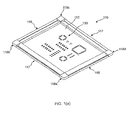
Figure 1(a) illustrates a perspective view of a printing screen unit in accordance with an embodiment of the present invention; -
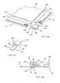
Figure 1(b) illustrates the upper side of one corner region of the printing screen unit ofFigure 1(a) ; -
Figure 1(c) illustrates the under side of the one corner region of the printing screen unit ofFigure 1(a) ; -
Figure 1(d) illustrates an exploded perspective view of the one corner region of the printing screen unit ofFigure 1(a) ; -
Figure 1(e) illustrates a vertical sectional view through an edge region of the printing screen unit ofFigure 1(a) ; -
Figure 1(f) illustrates an exploded perspective view of one corner piece of the printing screen unit ofFigure 1(a) ; -
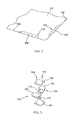
Figure 2 illustrates one corner region of an alternative printing screen for the printing screen unit ofFigure 1(a) , with the attachment elements being partially cut away for purposes of illustration; and -
Figure 3 illustrates an alternative corner piece for the printing screen unit ofFigure 1(a) . -
Figures 1(a) to (f) illustrate aprinting screen unit 110 in accordance with an embodiment of the present invention. - The
printing screen unit 110 comprises aprinting screen 112, in this embodiment of rectangular shape, and first and second pairs ofinterface members printing screen 112 and coupled bycorner pieces 118a-d such as to define a supporting frame. - The
printing screen 112 includes a pattern ofapertures 120 which define the pattern of deposits to be printed. The pattern ofapertures 120 can be formed, for example, by laser cutting or etching, as is well known in the art. In preferred embodiments theprinting screen 112 comprises a sheet of a metal, such as stainless steel, or a plastic. - The edges of the
printing screen 112 to which tensioning mechanisms are to be attached each comprise a plurality ofspaced projections 122 along the length thereof which define a castellated structure, and are folded to defineattachment elements printing screen 112 are each folded along a line intersecting theprojections 122, here at substantially a mid point of the length of theprojections 122, with each ofprojections 122 defining a hook element. In this embodiment the edges of theprinting screen 112 are folded such that theattachment elements printing screen 112. - The
projections 122 which define the castellated structures can, for example, be formed using a press tool or laser. Alternatively, theprojections 122 could be formed by electro-discharge machining (EDM) or water jet milling, which fabrication techniques would allowseveral printing screens 112 to be fabricated simultaneously. - The edges of the
printing screen 112 can be folded by using, for example, a roll or press tool. - In this embodiment, the configuration of the folded
projections 122, which define the castellated structures, advantageously provides for the application of a uniform tension over the main body of theprinting screen 112 in taking up the shape of the tensioning mechanisms, and thereby prevents distortion of the main body of theprinting screen 112, which typically has to be maintained flat. - The
interface members printing screen 112. - The
interface members attachment section 126 which comprises a first,lower body part 128 and a second,upper body part 130 and together define anattachment slot 132 which extends along the length thereof and in which a respective one of theattachment elements 124 of theprinting screen 112 is located. - The
attachment slot 132 comprises a first,support slot part 134, in this embodiment of linear section, which extends inwardly into theattachment section 126 from the inner edge of therespective interface member printing screen 112 which is inwardly adjacent therespective attachment element 124 of theprinting screen 112 and acts to support therespective interface member printing screen 112. - The
attachment slot 132 further comprises a second,attachment slot part 136 which includes anattachment surface 138 which extends inwardly and backwardly from the distal end of thesupport slot part 134 such as to define a hook arrangement which provides for attachment with therespective attachment element 124 of theprinting screen 112. In being inwardly inclined, theattachment surface 138 provides for the captive attachment of therespective attachment element 124 of theprinting screen 112. - The
interface members engagement section 140 which, relative to theprinting screen 112, is disposed outwardly of theattachment section 126 and provides for engagement to a tensioning mechanism. - The
engagement section 140 includes an inwardly-facingengagement surface 142, in this embodiment defined by a continuous surface, which extends along the length of therespective interface member engagement surface 142 is outwardly inclined from the free edge thereof relative to theprinting screen 112, such as to define a hook arrangement which provides for captive engagement with a tensioning mechanism. As will be appreciated, theengagement section 140, in being defined by a continuous surface, allows for fabrication by a wide variety of manufacturing techniques, such as machining, routing and extrusion, which are much simpler and cheaper techniques than the fabrication techniques required in fabricating the printing screens of the prior art printing screen units. - The
interface members recesses tongue elements respective corner pieces 118a-d, as will be described in more detail hereinbelow. - In this embodiment the
corner pieces 118a-d each comprise first andsecond coupling members respective corner pieces 118a-d. - In this embodiment the
first coupling member 152 comprises abody element 156 which includes aslot 158, here of the same rectangular section as therecesses interface members tongue element 160 for fitting in a respective one of therecesses interface members body element 156 in a second direction orthogonal to the first direction of theslot 158 therein. - In this embodiment the
second coupling member 154 comprises abody element 162, and atongue element 164 for fitting in an adjacent one of therecesses interface members body element 162. Thebody element 162 of thesecond coupling member 154 is configured to be a tight, snap-fit in theslot 158 in thebody element 156 of thefirst coupling member 154 such that, when inserted therein, thetongue elements coupling members coupling members - With this configuration, the
coupling members corner pieces 118a-d to be fitted, in enabling thetongue elements coupling members respective recesses interface members last corner piece 118a-d. It will be appreciated that three of thecorner pieces 118a-d can be pre-assembled and need not be assembled in situ. Indeed, in one embodiment three of thecorner pieces 118a-d can be fabricated as an integral unit, typically as a moulding or casting. - In this embodiment the
tongue elements coupling members recesses interface members tongue elements respective recesses printing screen 112. With this configuration, theinterface members interface members interface members printing screen 112. - In one alternative embodiment, as illustrated in
Figure 2 , theprinting screen 112 can include single,continuous attachment elements 124 along each of the edges thereof, with theprinting screen 112 including a plurality of flexingapertures 166 in spaced relation along each of the fold lines of the folds. This configuration, similarly to the castellated structures, advantageously provides for the application of a uniform tension over the main body of theprinting screen 112 and yet allows for flexing of theprinting screen 112 in taking up the shape of the tensioning mechanisms. - In another alternative embodiment, as illustrated in
Figure 3 , thecorner pieces 118a-d each comprise first andsecond coupling members tongue element 176 for fitting in a respective one of therecesses interface members structure 178 which provides for the locking of thecoupling members second capping members coupling members pins 184 for fixing the cappingmembers coupling members coupling members members coupling members - In this embodiment the
coupling members corner pieces 118a-d, in enabling thetongue elements 176 of a respective pair of thecoupling members respective recesses interface members structures 178 thereof in the manner of a jigsaw. - Finally, it will be understood that the present invention has been described in its preferred embodiments and can be modified in many different ways without departing from the scope of the invention as defined by the appended claims.
Claims (17)
- A printing screen unit, comprising:a printing screen (112), comprising a sheet having two pairs ofopposite edges, at least sections of which include attachment elements (124); andfirst and second pairs of interface members (116, 116, 117, 117) attached to the attachment elements (124) at each of the pairs of opposite edges of the sheet, wherein the interface members (116, 116, 117, 117) each include an attachment section (126) which is attached to an attachment element (124) at a respective edge of the sheet and an engagement section (140) which includes an engagement surface (142) which is adapted to engage a tensioning mechanism, and adjacent ends of each of the interface members (116, 116, 117, 117) are coupled together by corner pieces (118 a-d) to define a frame;characterised in that the engagement surface (142) of each interface member (116, 116, 117, 117) is inwardly-facing, defined by a continuous surface which extends along the length of the respective interface member (116, 116, 117, 117), and inclined outwardly from a free edge of the engagement surface (142) relative to the respective edge of the sheet.
- The printing screen unit of claim 1, wherein the corner pieces (118a-d) each comprise one of first and second recesses or projections (160, 164; 176, 176) and the ends of the interface members (116, 116, 117, 117) each include the other of recesses or projections (144, 146), which projections and recesses (144, 146, 160, 164; 176, 176) are engaged to couple the interface members (116, 116, 117, 117).
- The printing screen unit of claim 2, wherein the recesses and projections (144, 146, 160, 164; 176, 176) of the corner pieces (118a-d) and the interface members (116, 116, 117, 117) are configured such that the interface members (116, 116, 117, 117) move relatively to one another on being tensioned by a tensioning mechanism.
- The printing screen unit of any of claims 1 to 3, wherein at least one of the corner pieces (118a-d) comprises at least first and second coupling members (152, 154; 172, 174) which are configured to enable assembly thereof with the projections and recesses (144, 146, 160, 164; 176, 176) of the at least one corner piece (118a-d) and interface members (116, 116, 117, 117) in engagement, thereby enabling assembly of the frame with the Interface members (116, 116, 117, 117) thereof attached to the respective edges of the sheet.
- The printing screen unit of any of claims 1 to 4, wherein the attachment section (126) of each interface member (116, 116, 117, 117) includes an attachment surface (138) which is attached to the attachment element (124) at a respective edge of the sheet.
- The printing screen unit of claim 5, wherein the attachment surface (138) of each interface member (116, 116, 117, 117) is inclined inwardly from a free edge of the attachment surface (138) relative to the respective edge of the sheet.
- The printing screen unit of any of claims 1 to 6, wherein the at least sections of each pair of opposite edges of the sheet are folded to define attachment elements (124).
- The printing screen unit of claim 7, wherein the attachment elements (124) are each folded inwardly to enclose an acute angle with a major surface of the sheet.
- The printing screen unit of claim 7 or 8, wherein at least ones of the attachment elements (124) each comprise a plurality of projections (122) spaced along a length thereof.
- The printing screen unit of claim 9, wherein the projections (122) comprise rectangular projections.
- The printing screen unit of claim 9 or 10, wherein the projections (122) of each attachment element (124) define a castellated structure.
- The printing screen unit of any of claims 9 to 11, wherein the edges of the printing screen (112) are each folded along a line intersecting the projections (122), at substantially a mid point of the length of the projections (122), with each of the projections (122) defining a hook element.
- The printing screen unit of any of claims 7 to 12, wherein at least ones of the attachment elements (124) each comprise a single, continuous attachment element (124), and the sheet includes a plurality of flexing apertures (166) in spaced relation along each of the opposite edges thereof in zones overlapping fold lines of the respective folds.
- The printing screen unit of any of claims 1 to 13, wherein at least ones of the edges of the sheet have an attachment element (124) extending along substantially the length thereof.
- The printing screen unit of any of claims 1 to 14, wherein at least ones of the edges of the sheet have an attachment element (124) extending along part of the length thereof.
- The printing screen unit of any of claims 1 to 15, wherein the sheet includes a pattern of printing apertures (120) which define a pattern of deposits to be printed thereby.
- The printing screen unit of any of claims 1 to 16, wherein the sheet is a blank and includes no printing apertures therein.
Priority Applications (4)
| Application Number | Priority Date | Filing Date | Title |
|---|---|---|---|
| DK13167099.4T DK2626206T3 (en) | 2002-05-02 | 2003-04-30 | Printing screen unit |
| SI200332403T SI1499499T1 (en) | 2002-05-02 | 2003-04-30 | Printing screen units |
| EP11155890.4A EP2347901B2 (en) | 2002-05-02 | 2003-04-30 | Printing screen unit |
| EP13167099.4A EP2626206B1 (en) | 2002-05-02 | 2003-04-30 | printing screen unit |
Applications Claiming Priority (5)
| Application Number | Priority Date | Filing Date | Title |
|---|---|---|---|
| GB0210102A GB0210102D0 (en) | 2002-05-02 | 2002-05-02 | Improved stencil |
| GB0210102 | 2002-05-02 | ||
| GB0225130A GB0225130D0 (en) | 2002-10-29 | 2002-10-29 | Improved stencil |
| GB0225130 | 2002-10-29 | ||
| PCT/GB2003/001858 WO2003093012A1 (en) | 2002-05-02 | 2003-04-30 | Printing screens, frames therefor and printing screen units |
Related Child Applications (4)
| Application Number | Title | Priority Date | Filing Date |
|---|---|---|---|
| EP11155890.4A Division EP2347901B2 (en) | 2002-05-02 | 2003-04-30 | Printing screen unit |
| EP11155890.4A Division-Into EP2347901B2 (en) | 2002-05-02 | 2003-04-30 | Printing screen unit |
| EP13167099.4A Division EP2626206B1 (en) | 2002-05-02 | 2003-04-30 | printing screen unit |
| EP13167099.4A Division-Into EP2626206B1 (en) | 2002-05-02 | 2003-04-30 | printing screen unit |
Publications (2)
| Publication Number | Publication Date |
|---|---|
| EP1499499A1 EP1499499A1 (en) | 2005-01-26 |
| EP1499499B1 true EP1499499B1 (en) | 2014-09-17 |
Family
ID=29217379
Family Applications (3)
| Application Number | Title | Priority Date | Filing Date |
|---|---|---|---|
| EP13167099.4A Expired - Lifetime EP2626206B1 (en) | 2002-05-02 | 2003-04-30 | printing screen unit |
| EP11155890.4A Expired - Lifetime EP2347901B2 (en) | 2002-05-02 | 2003-04-30 | Printing screen unit |
| EP03732633.7A Expired - Lifetime EP1499499B1 (en) | 2002-05-02 | 2003-04-30 | Printing screen units |
Family Applications Before (2)
| Application Number | Title | Priority Date | Filing Date |
|---|---|---|---|
| EP13167099.4A Expired - Lifetime EP2626206B1 (en) | 2002-05-02 | 2003-04-30 | printing screen unit |
| EP11155890.4A Expired - Lifetime EP2347901B2 (en) | 2002-05-02 | 2003-04-30 | Printing screen unit |
Country Status (18)
| Country | Link |
|---|---|
| US (5) | US8069783B2 (en) |
| EP (3) | EP2626206B1 (en) |
| JP (1) | JP2005524551A (en) |
| KR (3) | KR20110036140A (en) |
| CN (1) | CN100519185C (en) |
| AT (1) | ATE537967T1 (en) |
| AU (1) | AU2003239661A1 (en) |
| BR (1) | BR0309627B1 (en) |
| DK (2) | DK1499499T3 (en) |
| ES (2) | ES2526087T3 (en) |
| GB (1) | GB2388073B (en) |
| HU (1) | HUE033750T2 (en) |
| MX (1) | MXPA04010790A (en) |
| PT (2) | PT2626206T (en) |
| RU (1) | RU2341377C2 (en) |
| SI (2) | SI1499499T1 (en) |
| TR (1) | TR201710711T4 (en) |
| WO (1) | WO2003093012A1 (en) |
Cited By (1)
| Publication number | Priority date | Publication date | Assignee | Title |
|---|---|---|---|---|
| EP4741170A1 (en) | 2024-11-06 | 2026-05-13 | ASMPT SMT Singapore Pte. Ltd. | Foil for a printing screen, printing screen and methods for making the foil and the screen |
Families Citing this family (34)
| Publication number | Priority date | Publication date | Assignee | Title |
|---|---|---|---|---|
| DE20308763U1 (en) * | 2003-05-23 | 2003-08-07 | Abril-Prießnitz, Yolanda, Llissa de Vall, Barcelona | Cover template for covering and printing on printed circuit boards and cover template unit |
| GB2407799B (en) | 2003-11-07 | 2006-02-08 | Dek Int Gmbh | A frame unit for tensioning a printing screen and a jig for fitting a printing screen to or removing a printing screen from a frame unit |
| DE102004028448B4 (en) | 2004-06-14 | 2007-08-02 | Lpkf Laser & Elektronika D.O.O. | Protective device for holding a printing template and stencil clamping frame |
| GB2419357B (en) * | 2004-10-20 | 2010-04-21 | Dek Int Gmbh | Mandrels for electroforming printing screens, electroforming systems for electroforming printing screens, methods of electroforming printing screens. |
| DE102004051935B4 (en) * | 2004-10-25 | 2006-09-28 | Metaq Gmbh | stencil |
| EP1651019B1 (en) | 2004-10-25 | 2008-05-14 | METAQ GmbH | Stencil, frame to stretch said stencil as well as process and device to manufacture stencil |
| NL1028790C2 (en) * | 2005-04-18 | 2006-10-20 | Stork Veco Bv | Method for electroforming a stencil and such a stencil. |
| JP2009101514A (en) * | 2006-02-08 | 2009-05-14 | Hirotake Kasuya | Stretching implement of sheet-shaped material |
| GB2435011B (en) | 2006-02-08 | 2010-06-02 | Dek Int Gmbh | Printing screens, frames therefor and printing screen units |
| JP4880379B2 (en) * | 2006-06-23 | 2012-02-22 | 粕谷 普烈 | A frame with adjustable template tension |
| GB2455493A (en) * | 2007-10-08 | 2009-06-17 | Dek Int Gmbh | Frame assembly for tensioning de-mountable printing screens |
| WO2011120700A2 (en) | 2010-04-01 | 2011-10-06 | Dtg International Gmbh | Printing screen and method of manufacturing the same |
| GB2497086A (en) | 2011-11-29 | 2013-06-05 | Architectural & Metal Systems Ltd | Printing screen |
| ES2420033B1 (en) * | 2012-01-26 | 2014-10-08 | Ibil Laser S.L. | Screen printing for surface mounting devices |
| WO2014035528A2 (en) * | 2012-06-15 | 2014-03-06 | Tufts University | Paint-on approach for fabrication of electrically active structures |
| US9631417B2 (en) * | 2012-12-21 | 2017-04-25 | Milgard Manufacturing Incorporated | Screen corner attachment |
| GB201306154D0 (en) * | 2013-04-05 | 2013-05-22 | Tannlin Group Ltd | Printing screen |
| US9351406B2 (en) | 2013-12-17 | 2016-05-24 | QTS Engineering, Inc. | Stencil foil assembly |
| KR101440062B1 (en) * | 2014-02-19 | 2014-09-17 | (주)디앤에프 | Screen plate making assembly for variety color printing |
| CN104176396A (en) * | 2014-04-08 | 2014-12-03 | 邵妮 | Corner fitting for container, container and container-type movable house |
| US20160332437A1 (en) * | 2015-05-11 | 2016-11-17 | Arthur Guidi | Solder Paste Stencil with Integral Stiffener and Mounting Device |
| KR101656022B1 (en) * | 2016-03-24 | 2016-09-08 | (주)본트로닉스 | Printing screen units |
| US10421315B2 (en) | 2016-03-26 | 2019-09-24 | Francois Roy | Device for tensioning a canvas on a frame and kit for assembling a frame for canvas |
| KR101685899B1 (en) * | 2016-04-28 | 2016-12-13 | (주)본트로닉스 | Fixing apparatus for frame of printing screen |
| KR101931928B1 (en) * | 2017-11-24 | 2018-12-24 | (주)본트로닉스 | Fixing apparatus for frame of printing screen |
| US20200180300A1 (en) * | 2018-07-26 | 2020-06-11 | Ricky Paul Bennett | Meshless foil stencil frame |
| USD909769S1 (en) | 2018-10-25 | 2021-02-09 | Gesplan Gestion Conseil Inc. | Stretcher bar frame |
| KR102154825B1 (en) * | 2019-01-18 | 2020-09-11 | (주)본트로닉스 | Printing screen units |
| GB2586610A (en) | 2019-08-28 | 2021-03-03 | Asm Assembly Systems Singapore Pte Ltd | Reinforced tensioning frame |
| GB2588633B (en) * | 2019-10-29 | 2023-11-22 | Tannlin Tech Limited | Precision cut printing screen |
| WO2021092152A1 (en) * | 2019-11-05 | 2021-05-14 | Blue Ring Stencils, LLC | Frame assembly for surface mount technology stencil |
| GB201916469D0 (en) | 2019-11-13 | 2019-12-25 | Asm Assembly Systems Singapore Pte Ltd | Screen loading system |
| KR102562472B1 (en) * | 2021-07-30 | 2023-08-03 | 한빅솔라(주) | Reusable detachable sub-frame assemble of stencil mask |
| GB2628536A (en) | 2023-03-25 | 2024-10-02 | Asmpt Smt Singapore Pte Ltd | Front-loading tensioning frame |
Citations (2)
| Publication number | Priority date | Publication date | Assignee | Title |
|---|---|---|---|---|
| US2218451A (en) * | 1938-09-27 | 1940-10-15 | Owens Illinois Glass Co | Stencil screen construction |
| US5113611A (en) * | 1991-05-11 | 1992-05-19 | Rosson Gene T | Expandable screen tensioning frame with expansion devices |
Family Cites Families (55)
| Publication number | Priority date | Publication date | Assignee | Title |
|---|---|---|---|---|
| US2925774A (en) * | 1955-11-08 | 1960-02-23 | Admiral Corp | Frame for a screen |
| US3280731A (en) † | 1964-01-28 | 1966-10-25 | Electrostatic Printing Corp | Stencil screen frame attachment and tensioning means |
| US3416445A (en) † | 1965-10-18 | 1968-12-17 | Theodore H. Krueger Jr. | Screen stencil with separate border strips |
| US3359663A (en) † | 1967-02-23 | 1967-12-26 | James A Black | Stencil screen frame |
| US3485165A (en) * | 1968-01-08 | 1969-12-23 | Richard G Hughes | Silk-screening frame |
| US3482343A (en) | 1968-01-22 | 1969-12-09 | Kaino J Hamu | Frame for stressing sheet material |
| US3608482A (en) * | 1969-10-31 | 1971-09-28 | American Screen Process Equip | Locking bar for screen-printing frame |
| US3788216A (en) * | 1971-12-08 | 1974-01-29 | Dia Print Co Inc | Adjustable screen printing chase |
| JPS5224709A (en) | 1975-07-09 | 1977-02-24 | Hitachi Ltd | Screen mask for printing |
| JPS5328778A (en) | 1976-08-27 | 1978-03-17 | Akio Nagayoshi | Bonding of synthetic resin nets |
| US4190974A (en) * | 1978-06-21 | 1980-03-04 | Siler Todd L | Artists' canvas and frame assembly |
| IE50691B1 (en) † | 1979-11-15 | 1986-06-25 | Davies Peter | A metal printing screen and a method for producing the printing screen |
| DE3043666A1 (en) | 1980-11-19 | 1982-07-08 | Elmar Dipl.-Kfm. Dr. 8000 München Messerschmitt | Screen-printing frame with detachable screen - has screen frame inserted and secured in peripheral mounting portion |
| US4409749A (en) | 1981-09-08 | 1983-10-18 | Hamu Kaino J | Stretch frame |
| US4442772A (en) | 1982-10-26 | 1984-04-17 | American Screen Printing Equipment Company | Screen tensioning apparatus |
| US4893556A (en) | 1987-02-23 | 1990-01-16 | Tdk Corporation | Screen printer with double doctor/squeegee, printing pressure sensor and aligning mechanism |
| US5136797A (en) † | 1989-09-09 | 1992-08-11 | Hildebrandt Greg A | Frame having shiftable bars with flexible ends for securing fabric using adhesive |
| JPH03224145A (en) * | 1990-01-30 | 1991-10-03 | Sony Corp | Production of optical disk |
| US5076162A (en) * | 1990-10-04 | 1991-12-31 | Goin Bobby G | Expandable mesh frame |
| US5220867A (en) * | 1991-07-15 | 1993-06-22 | Carpenter Robert C | Adjustable tension silk screen frame |
| US5327828A (en) † | 1991-09-17 | 1994-07-12 | Barocas Ervin V | Clamp and process for protecting printing screens and frames |
| GB2264460B (en) | 1992-06-03 | 1994-02-16 | David Godfrey Williams | Improved stencil or mask for applying solder to circuit boards and support frame |
| US5379691A (en) * | 1992-09-14 | 1995-01-10 | Hamu; Alan J. | Screen printing frame assembly with screen anchors |
| GB9220700D0 (en) | 1992-10-01 | 1992-11-11 | Cane Paul | A screen printing stencil |
| GB9220727D0 (en) | 1992-10-01 | 1992-11-11 | Cane Paul | Screen printing tensioning device |
| SI9300252B (en) | 1993-05-12 | 2002-02-28 | Zeltra Podjetje Za Projektiranje | Holding-steching arrangement for printer stencils on printing table for printed circuits |
| US5819651A (en) * | 1993-05-12 | 1998-10-13 | Zeltra, Podjetje Za Projektiranje, Proizvodnjo In Trgovino Elektrotehnike,Naklo,D.O.O. | Clamping-stretching system for stencils for screen printers,with printing table for PC boards |
| EP0790892B1 (en) | 1994-11-05 | 1999-03-10 | BEBRO-ELECTRONIC BENGEL & BROSS GmbH | Stencil holder |
| US5941171A (en) | 1994-11-05 | 1999-08-24 | Bebro-Electronic Bengel & Bross Gmbh | Stencil holder |
| GB2292115B (en) † | 1994-11-17 | 1996-07-10 | Nicholas Mark Baker | Solder stencil mounting frame |
| JPH08150698A (en) | 1994-11-25 | 1996-06-11 | Gunma Toobi:Kk | Multicolor printing apparatus and multicolor printing method using the same |
| GB2303333B (en) * | 1995-07-20 | 1998-09-23 | David Godfrey Williams | Improved apparatus for supporting and tensioning a stencil or mask for use in applying solder paste to circuit boards and a mounting support means therefor |
| JPH09187914A (en) † | 1996-01-10 | 1997-07-22 | Sony Corp | Screen printing equipment |
| JP3078225B2 (en) | 1996-03-22 | 2000-08-21 | 鐘紡株式会社 | Screen-shaped plated product made of mesh-like fabric using core-sheath composite filament and cylinder for rotary screen |
| DE19615058C2 (en) | 1996-04-17 | 1998-06-18 | Tele Quarz Gmbh | Clamping device and stencils for stencil or screen printing |
| JP3257397B2 (en) | 1996-05-09 | 2002-02-18 | 松下電器産業株式会社 | Screen mask manufacturing method |
| GB2317366B (en) | 1996-09-19 | 2000-09-20 | David Godfrey Williams | Improved stencil tensioning frame and stencil mounting/dismounting apparatus therefor |
| JP2926224B2 (en) | 1997-02-28 | 1999-07-28 | 株式会社石井表記 | Metal gauze frame for silk plate making and method for producing silk plate making using the frame |
| US5979313A (en) | 1997-03-25 | 1999-11-09 | Bebro-Electronic Bengel & Bross Gmbh | Stencil holder having independently movable tensioning elements |
| JP3705313B2 (en) | 1997-05-22 | 2005-10-12 | 凸版印刷株式会社 | Screen printing screen plate and manufacturing method thereof |
| DE19749449C1 (en) | 1997-11-10 | 1999-01-07 | Lpkf D O O | Tensioning frame for metal or plastic templates |
| JP3078775B2 (en) | 1997-12-10 | 2000-08-21 | 東京プロセスサービス株式会社 | Combination mask |
| US5983790A (en) * | 1998-04-27 | 1999-11-16 | Pnc2, Inc. | Foil screen registering apparatus and method |
| US6561089B1 (en) | 1999-09-20 | 2003-05-13 | Eugene F. Newman, Jr. | Screen assembly having border construction with cupping features and method of making |
| JP3639482B2 (en) | 1999-12-01 | 2005-04-20 | 理想科学工業株式会社 | Screen printing apparatus and stencil sheet assembly |
| US6318255B1 (en) * | 2000-02-07 | 2001-11-20 | James D. Larson | Method of attaching coated silk screen fabric to a frame and the reusable silk screen |
| US6427588B1 (en) | 2000-09-05 | 2002-08-06 | Christopher Kline | Device and method for supporting and tensioning a silk screen |
| JPWO2002055304A1 (en) | 2001-01-16 | 2004-05-13 | 粕谷 普烈 | Screen for screen printing, screen plate, screen frame, laminating method of screen, stretching method of screen, painting canvas, advertising sheet and plane mirror |
| GB2371519A (en) * | 2001-01-25 | 2002-07-31 | Dek Printing Machines Ltd | Printing screen support and assembly jig |
| US6494134B2 (en) * | 2001-04-17 | 2002-12-17 | Gunter Erdmann | Frame for foil stencil and stencil foil assembly |
| GB2364961B (en) | 2001-08-10 | 2002-06-26 | Tecan Components Ltd | Stencil for use with stencil mounting frame |
| US6588334B2 (en) * | 2001-10-09 | 2003-07-08 | Ronald Salisbury | Screen printing frame assembly having hollow connectors with drain holes |
| DE10154265A1 (en) * | 2001-11-05 | 2003-05-22 | Laserjob Gmbh | Tensioning frame with printing template |
| FR2840851B1 (en) | 2002-06-13 | 2004-09-03 | Novatec Sa Soc | METHOD FOR IMPLEMENTING AN ADAPTED SCREEN STENCIL FOR DISSOCIATING THE TREATMENT OF FILLING AND MOLDING PHASES |
| DE20209385U1 (en) | 2002-06-17 | 2002-08-29 | LTC Laserdienstleistungen GmbH, 75331 Engelsbrand | template |
-
2003
- 2003-04-30 AT AT11155890T patent/ATE537967T1/en active
- 2003-04-30 TR TR2017/10711T patent/TR201710711T4/en unknown
- 2003-04-30 ES ES03732633.7T patent/ES2526087T3/en not_active Expired - Lifetime
- 2003-04-30 KR KR1020117006715A patent/KR20110036140A/en not_active Ceased
- 2003-04-30 MX MXPA04010790A patent/MXPA04010790A/en active IP Right Grant
- 2003-04-30 EP EP13167099.4A patent/EP2626206B1/en not_active Expired - Lifetime
- 2003-04-30 JP JP2004501168A patent/JP2005524551A/en active Pending
- 2003-04-30 PT PT131670994T patent/PT2626206T/en unknown
- 2003-04-30 US US10/513,452 patent/US8069783B2/en not_active Expired - Lifetime
- 2003-04-30 KR KR1020097021562A patent/KR101102777B1/en not_active Expired - Lifetime
- 2003-04-30 SI SI200332403T patent/SI1499499T1/en unknown
- 2003-04-30 SI SI200332536T patent/SI2626206T1/en unknown
- 2003-04-30 HU HUE13167099A patent/HUE033750T2/en unknown
- 2003-04-30 BR BRPI0309627-0A patent/BR0309627B1/en active IP Right Grant
- 2003-04-30 DK DK03732633.7T patent/DK1499499T3/en active
- 2003-04-30 WO PCT/GB2003/001858 patent/WO2003093012A1/en not_active Ceased
- 2003-04-30 CN CNB038149559A patent/CN100519185C/en not_active Expired - Lifetime
- 2003-04-30 ES ES13167099.4T patent/ES2635134T3/en not_active Expired - Lifetime
- 2003-04-30 DK DK13167099.4T patent/DK2626206T3/en active
- 2003-04-30 RU RU2004135104/12A patent/RU2341377C2/en active
- 2003-04-30 EP EP11155890.4A patent/EP2347901B2/en not_active Expired - Lifetime
- 2003-04-30 AU AU2003239661A patent/AU2003239661A1/en not_active Abandoned
- 2003-04-30 KR KR1020047017638A patent/KR20050026386A/en not_active Ceased
- 2003-04-30 EP EP03732633.7A patent/EP1499499B1/en not_active Expired - Lifetime
- 2003-04-30 GB GB0309909A patent/GB2388073B/en not_active Expired - Lifetime
- 2003-04-30 PT PT37326337T patent/PT1499499E/en unknown
-
2011
- 2011-04-26 US US13/094,419 patent/US8490545B2/en not_active Expired - Lifetime
-
2013
- 2013-07-23 US US13/948,276 patent/US8904929B2/en not_active Expired - Lifetime
-
2014
- 2014-12-02 US US14/558,257 patent/US9623650B2/en not_active Expired - Fee Related
-
2017
- 2017-04-17 US US15/488,973 patent/US10081211B2/en not_active Expired - Lifetime
Patent Citations (2)
| Publication number | Priority date | Publication date | Assignee | Title |
|---|---|---|---|---|
| US2218451A (en) * | 1938-09-27 | 1940-10-15 | Owens Illinois Glass Co | Stencil screen construction |
| US5113611A (en) * | 1991-05-11 | 1992-05-19 | Rosson Gene T | Expandable screen tensioning frame with expansion devices |
Cited By (1)
| Publication number | Priority date | Publication date | Assignee | Title |
|---|---|---|---|---|
| EP4741170A1 (en) | 2024-11-06 | 2026-05-13 | ASMPT SMT Singapore Pte. Ltd. | Foil for a printing screen, printing screen and methods for making the foil and the screen |
Also Published As
Similar Documents
| Publication | Publication Date | Title |
|---|---|---|
| US10081211B2 (en) | Printing screens, frames therefor and printing screen units | |
| EP1986853B1 (en) | Supporting frame for a printing screen | |
| CN101544095B (en) | Printing screen, its frame and printing screen device | |
| HK1153986B (en) | Printing screen unit | |
| HK1187576A (en) | Printing screen units | |
| HK1187576B (en) | Printing screen units | |
| HK1125337B (en) | Supporting frame for a printing screen |
Legal Events
| Date | Code | Title | Description |
|---|---|---|---|
| PUAI | Public reference made under article 153(3) epc to a published international application that has entered the european phase |
Free format text: ORIGINAL CODE: 0009012 |
|
| 17P | Request for examination filed |
Effective date: 20041122 |
|
| AK | Designated contracting states |
Kind code of ref document: A1 Designated state(s): AT BE BG CH CY CZ DE DK EE ES FI FR GB GR HU IE IT LI LU MC NL PT RO SE SI SK TR |
|
| AX | Request for extension of the european patent |
Extension state: AL LT LV MK |
|
| RAP1 | Party data changed (applicant data changed or rights of an application transferred) |
Owner name: TANNLIN LIMITED |
|
| DAX | Request for extension of the european patent (deleted) | ||
| RAP1 | Party data changed (applicant data changed or rights of an application transferred) |
Owner name: DEK VECTORGUARD LIMITED |
|
| 17Q | First examination report despatched |
Effective date: 20110428 |
|
| TPAC | Observations filed by third parties |
Free format text: ORIGINAL CODE: EPIDOSNTIPA |
|
| TPAC | Observations filed by third parties |
Free format text: ORIGINAL CODE: EPIDOSNTIPA |
|
| GRAP | Despatch of communication of intention to grant a patent |
Free format text: ORIGINAL CODE: EPIDOSNIGR1 |
|
| INTG | Intention to grant announced |
Effective date: 20131007 |
|
| GRAP | Despatch of communication of intention to grant a patent |
Free format text: ORIGINAL CODE: EPIDOSNIGR1 |
|
| INTG | Intention to grant announced |
Effective date: 20131211 |
|
| GRAF | Information related to payment of grant fee modified |
Free format text: ORIGINAL CODE: EPIDOSCIGR3 |
|
| GRAS | Grant fee paid |
Free format text: ORIGINAL CODE: EPIDOSNIGR3 |
|
| GRAA | (expected) grant |
Free format text: ORIGINAL CODE: 0009210 |
|
| AK | Designated contracting states |
Kind code of ref document: B1 Designated state(s): AT BE BG CH CY CZ DE DK EE ES FI FR GB GR HU IE IT LI LU MC NL PT RO SE SI SK TR |
|
| REG | Reference to a national code |
Ref country code: GB Ref legal event code: FG4D |
|
| REG | Reference to a national code |
Ref country code: DE Ref legal event code: R081 Ref document number: 60346757 Country of ref document: DE Owner name: ASM ASSEMBLY SYSTEMS WEYMOUTH LTD., GB Free format text: FORMER OWNER: TANNLIN LTD., IRVINE, GB |
|
| REG | Reference to a national code |
Ref country code: CH Ref legal event code: EP |
|
| REG | Reference to a national code |
Ref country code: IE Ref legal event code: FG4D |
|
| REG | Reference to a national code |
Ref country code: AT Ref legal event code: REF Ref document number: 687488 Country of ref document: AT Kind code of ref document: T Effective date: 20141015 |
|
| REG | Reference to a national code |
Ref country code: DE Ref legal event code: R096 Ref document number: 60346757 Country of ref document: DE Effective date: 20141030 |
|
| REG | Reference to a national code |
Ref country code: RO Ref legal event code: EPE |
|
| REG | Reference to a national code |
Ref country code: PT Ref legal event code: SC4A Free format text: AVAILABILITY OF NATIONAL TRANSLATION Effective date: 20141215 |
|
| REG | Reference to a national code |
Ref country code: CH Ref legal event code: NV Representative=s name: HEPP WENGER RYFFEL AG, CH |
|
| REG | Reference to a national code |
Ref country code: ES Ref legal event code: FG2A Ref document number: 2526087 Country of ref document: ES Kind code of ref document: T3 Effective date: 20150105 Ref country code: DK Ref legal event code: T3 Effective date: 20141216 |
|
| REG | Reference to a national code |
Ref country code: SE Ref legal event code: TRGR |
|
| REG | Reference to a national code |
Ref country code: NL Ref legal event code: T3 |
|
| RAP2 | Party data changed (patent owner data changed or rights of a patent transferred) |
Owner name: ASM VECTORGUARD LIMITED |
|
| PG25 | Lapsed in a contracting state [announced via postgrant information from national office to epo] |
Ref country code: CY Free format text: LAPSE BECAUSE OF FAILURE TO SUBMIT A TRANSLATION OF THE DESCRIPTION OR TO PAY THE FEE WITHIN THE PRESCRIBED TIME-LIMIT Effective date: 20140917 |
|
| REG | Reference to a national code |
Ref country code: GR Ref legal event code: EP Ref document number: 20140402566 Country of ref document: GR Effective date: 20150128 |
|
| PG25 | Lapsed in a contracting state [announced via postgrant information from national office to epo] |
Ref country code: EE Free format text: LAPSE BECAUSE OF FAILURE TO SUBMIT A TRANSLATION OF THE DESCRIPTION OR TO PAY THE FEE WITHIN THE PRESCRIBED TIME-LIMIT Effective date: 20140917 |
|
| REG | Reference to a national code |
Ref country code: SK Ref legal event code: T3 Ref document number: E 17980 Country of ref document: SK |
|
| REG | Reference to a national code |
Ref country code: DE Ref legal event code: R097 Ref document number: 60346757 Country of ref document: DE |
|
| PLBE | No opposition filed within time limit |
Free format text: ORIGINAL CODE: 0009261 |
|
| STAA | Information on the status of an ep patent application or granted ep patent |
Free format text: STATUS: NO OPPOSITION FILED WITHIN TIME LIMIT |
|
| 26N | No opposition filed |
Effective date: 20150618 |
|
| REG | Reference to a national code |
Ref country code: HU Ref legal event code: AG4A Ref document number: E023480 Country of ref document: HU |
|
| PG25 | Lapsed in a contracting state [announced via postgrant information from national office to epo] |
Ref country code: MC Free format text: LAPSE BECAUSE OF FAILURE TO SUBMIT A TRANSLATION OF THE DESCRIPTION OR TO PAY THE FEE WITHIN THE PRESCRIBED TIME-LIMIT Effective date: 20140917 Ref country code: LU Free format text: LAPSE BECAUSE OF FAILURE TO SUBMIT A TRANSLATION OF THE DESCRIPTION OR TO PAY THE FEE WITHIN THE PRESCRIBED TIME-LIMIT Effective date: 20150430 |
|
| REG | Reference to a national code |
Ref country code: FR Ref legal event code: PLFP Year of fee payment: 14 |
|
| REG | Reference to a national code |
Ref country code: FR Ref legal event code: PLFP Year of fee payment: 15 |
|
| REG | Reference to a national code |
Ref country code: CH Ref legal event code: PFA Owner name: ASM VECTORGUARD LIMITED, GB Free format text: FORMER OWNER: DEK VECTORGUARD LIMITED, GB Ref country code: CH Ref legal event code: PUE Owner name: ASM ASSEMBLY SYSTEMS WEYMOUTH LTD., GB Free format text: FORMER OWNER: ASM VECTORGUARD LIMITED, GB |
|
| REG | Reference to a national code |
Ref country code: DE Ref legal event code: R082 Ref document number: 60346757 Country of ref document: DE Representative=s name: BTB IP BUNGARTZ BALTZER PARTNERSCHAFT MBB PATE, DE Ref country code: DE Ref legal event code: R082 Ref document number: 60346757 Country of ref document: DE Representative=s name: BUNGARTZ CHRISTOPHERSEN PARTNERSCHAFT MBB PATE, DE Ref country code: DE Ref legal event code: R081 Ref document number: 60346757 Country of ref document: DE Owner name: ASM ASSEMBLY SYSTEMS WEYMOUTH LTD., GB Free format text: FORMER OWNER: DEK VECTORGUARD LTD., KILMARNOCK, AYRSHIRE, GB |
|
| REG | Reference to a national code |
Ref country code: DE Ref legal event code: R082 Ref document number: 60346757 Country of ref document: DE Ref country code: DE Ref legal event code: R082 Ref document number: 60346757 Country of ref document: DE Representative=s name: BUNGARTZ CHRISTOPHERSEN PARTNERSCHAFT MBB PATE, DE Ref country code: DE Ref legal event code: R082 Ref document number: 60346757 Country of ref document: DE Representative=s name: BTB IP BUNGARTZ BALTZER PARTNERSCHAFT MBB PATE, DE |
|
| REG | Reference to a national code |
Ref country code: SI Ref legal event code: SP73 Owner name: ASM ASSEMBLY SYSTEMS WEYMOUTH LTD.; GB Effective date: 20170731 |
|
| REG | Reference to a national code |
Ref country code: HU Ref legal event code: GB9C Owner name: ASM ASSEMBLY SYSTEMS WEYMOUTH LTD., GB Free format text: FORMER OWNER(S): DEK VECTORGUARD LIMITED, GB |
|
| REG | Reference to a national code |
Ref country code: SK Ref legal event code: PC4A Ref document number: E 17980 Country of ref document: SK Owner name: ASM ASSEMBLY SYSTEMS WEYMOUTH LTD., WEYMOUTH, GB Free format text: FORMER OWNER: ASM VECTORGUARD LIMITED, KILMARNOCK, AYRSHIRE, GB Effective date: 20170509 |
|
| REG | Reference to a national code |
Ref country code: GB Ref legal event code: 732E Free format text: REGISTERED BETWEEN 20170907 AND 20170913 |
|
| REG | Reference to a national code |
Ref country code: NL Ref legal event code: HC Owner name: ASM VECTORGUARD LIMITED; GB Free format text: DETAILS ASSIGNMENT: CHANGE OF OWNER(S), CHANGE OF OWNER(S) NAME; FORMER OWNER NAME: DEK VECTORGUARD LIMITED Effective date: 20170808 Ref country code: NL Ref legal event code: PD Owner name: ASM ASSEMBLY SYSTEMS WEYMOUTH LTD.; GB Free format text: DETAILS ASSIGNMENT: CHANGE OF OWNER(S), ASSIGNMENT; FORMER OWNER NAME: ASM VECTORGUARD LIMITED Effective date: 20170808 |
|
| REG | Reference to a national code |
Ref country code: DE Ref legal event code: R082 Ref document number: 60346757 Country of ref document: DE Representative=s name: BTB IP BUNGARTZ BALTZER PARTNERSCHAFT MBB PATE, DE |
|
| REG | Reference to a national code |
Ref country code: ES Ref legal event code: PC2A Owner name: ASM ASSEMBLY SYSTEMS WEYMOUTH LTD. Effective date: 20171108 |
|
| REG | Reference to a national code |
Ref country code: FR Ref legal event code: TP Owner name: ASM ASSEMBLY SYSTEMS WEYMOUTH LTD., GB Effective date: 20171025 |
|
| REG | Reference to a national code |
Ref country code: AT Ref legal event code: PC Ref document number: 687488 Country of ref document: AT Kind code of ref document: T Owner name: ASM ASSEMBLY SYSTEMS WEYMOUTH LTD., GB Effective date: 20171207 |
|
| REG | Reference to a national code |
Ref country code: BE Ref legal event code: FP Effective date: 20141217 Ref country code: BE Ref legal event code: HC Owner name: ASM VECTORGUARD LIMITED; GB Free format text: DETAILS ASSIGNMENT: CHANGE OF OWNER(S), CHANGEMENT DE NOM DU PROPRIETAIRE; FORMER OWNER NAME: DEK VECTORGUARD LIMITED Effective date: 20170804 Ref country code: BE Ref legal event code: PD Owner name: ASM ASSEMBLY SYSTEMS WEYMOUTH LTD.; GB Free format text: DETAILS ASSIGNMENT: CHANGE OF OWNER(S), CESSION; FORMER OWNER NAME: ASM VECTORGUARD LIMITED Effective date: 20170804 |
|
| REG | Reference to a national code |
Ref country code: FR Ref legal event code: PLFP Year of fee payment: 16 |
|
| PGFP | Annual fee paid to national office [announced via postgrant information from national office to epo] |
Ref country code: NL Payment date: 20220420 Year of fee payment: 20 |
|
| PGFP | Annual fee paid to national office [announced via postgrant information from national office to epo] |
Ref country code: SK Payment date: 20220427 Year of fee payment: 20 Ref country code: SE Payment date: 20220421 Year of fee payment: 20 Ref country code: RO Payment date: 20220426 Year of fee payment: 20 Ref country code: PT Payment date: 20220421 Year of fee payment: 20 Ref country code: IT Payment date: 20220420 Year of fee payment: 20 Ref country code: IE Payment date: 20220420 Year of fee payment: 20 Ref country code: HU Payment date: 20220417 Year of fee payment: 20 Ref country code: GB Payment date: 20220420 Year of fee payment: 20 Ref country code: FR Payment date: 20220420 Year of fee payment: 20 Ref country code: ES Payment date: 20220629 Year of fee payment: 20 Ref country code: DK Payment date: 20220422 Year of fee payment: 20 Ref country code: DE Payment date: 20220420 Year of fee payment: 20 Ref country code: CZ Payment date: 20220429 Year of fee payment: 20 Ref country code: BG Payment date: 20220421 Year of fee payment: 20 |
|
| PGFP | Annual fee paid to national office [announced via postgrant information from national office to epo] |
Ref country code: TR Payment date: 20220428 Year of fee payment: 20 Ref country code: SI Payment date: 20220427 Year of fee payment: 20 Ref country code: GR Payment date: 20220414 Year of fee payment: 20 Ref country code: FI Payment date: 20220421 Year of fee payment: 20 Ref country code: CH Payment date: 20220421 Year of fee payment: 20 Ref country code: BE Payment date: 20220421 Year of fee payment: 20 Ref country code: AT Payment date: 20220421 Year of fee payment: 20 |
|
| REG | Reference to a national code |
Ref country code: DE Ref legal event code: R071 Ref document number: 60346757 Country of ref document: DE |
|
| REG | Reference to a national code |
Ref country code: DK Ref legal event code: EUP Expiry date: 20230430 |
|
| REG | Reference to a national code |
Ref country code: NL Ref legal event code: MK Effective date: 20230429 |
|
| REG | Reference to a national code |
Ref country code: BE Ref legal event code: MK Effective date: 20230430 |
|
| REG | Reference to a national code |
Ref country code: CH Ref legal event code: PL |
|
| REG | Reference to a national code |
Ref country code: SK Ref legal event code: MK4A Ref document number: E 17980 Country of ref document: SK Expiry date: 20230430 |
|
| REG | Reference to a national code |
Ref country code: IE Ref legal event code: MK9A Ref country code: GB Ref legal event code: PE20 Expiry date: 20230429 |
|
| REG | Reference to a national code |
Ref country code: ES Ref legal event code: FD2A Effective date: 20230526 |
|
| REG | Reference to a national code |
Ref country code: SE Ref legal event code: EUG |
|
| REG | Reference to a national code |
Ref country code: AT Ref legal event code: MK07 Ref document number: 687488 Country of ref document: AT Kind code of ref document: T Effective date: 20230430 |
|
| P01 | Opt-out of the competence of the unified patent court (upc) registered |
Effective date: 20230530 |
|
| PG25 | Lapsed in a contracting state [announced via postgrant information from national office to epo] |
Ref country code: PT Free format text: LAPSE BECAUSE OF EXPIRATION OF PROTECTION Effective date: 20230511 Ref country code: IE Free format text: LAPSE BECAUSE OF EXPIRATION OF PROTECTION Effective date: 20230430 Ref country code: ES Free format text: LAPSE BECAUSE OF EXPIRATION OF PROTECTION Effective date: 20230501 Ref country code: CZ Free format text: LAPSE BECAUSE OF EXPIRATION OF PROTECTION Effective date: 20230430 |
|
| REG | Reference to a national code |
Ref country code: HU Ref legal event code: HC9C Owner name: ASMPT SMT UK LIMITED, GB Free format text: FORMER OWNER(S): DEK VECTORGUARD LIMITED, GB; ASM ASSEMBLY SYSTEMS WEYMOUTH LTD., GB |
|
| PG25 | Lapsed in a contracting state [announced via postgrant information from national office to epo] |
Ref country code: SK Free format text: LAPSE BECAUSE OF EXPIRATION OF PROTECTION Effective date: 20230430 Ref country code: SI Free format text: LAPSE BECAUSE OF EXPIRATION OF PROTECTION Effective date: 20230501 |
|
| PG25 | Lapsed in a contracting state [announced via postgrant information from national office to epo] |
Ref country code: GB Free format text: LAPSE BECAUSE OF EXPIRATION OF PROTECTION Effective date: 20230429 |