EP1499428B1 - An air-gas mixer device, particularly for gas burners and similar apparatus - Google Patents
An air-gas mixer device, particularly for gas burners and similar apparatus Download PDFInfo
- Publication number
- EP1499428B1 EP1499428B1 EP02733230A EP02733230A EP1499428B1 EP 1499428 B1 EP1499428 B1 EP 1499428B1 EP 02733230 A EP02733230 A EP 02733230A EP 02733230 A EP02733230 A EP 02733230A EP 1499428 B1 EP1499428 B1 EP 1499428B1
- Authority
- EP
- European Patent Office
- Prior art keywords
- duct
- flow
- air
- mixer device
- choke
- Prior art date
- Legal status (The legal status is an assumption and is not a legal conclusion. Google has not performed a legal analysis and makes no representation as to the accuracy of the status listed.)
- Expired - Lifetime
Links
Images

Classifications
-
- F—MECHANICAL ENGINEERING; LIGHTING; HEATING; WEAPONS; BLASTING
- F23—COMBUSTION APPARATUS; COMBUSTION PROCESSES
- F23D—BURNERS
- F23D14/00—Burners for combustion of a gas, e.g. of a gas stored under pressure as a liquid
- F23D14/46—Details
- F23D14/62—Mixing devices; Mixing tubes
Definitions
- the present invention relates to an air-gas mixer device, designed particularly but not exclusively for gas burners with forced ventilation, according to the preamble to main Claim 1.
- devices of the above-mentioned type are used in boilers and similar apparatus with gas burners, mainly for domestic use and, in particular, in applications with forced ventilation.
- a device having the characteristics specified above is also known from the Applicant's International application PCT/IT01/00087 , published as WO-A-02/061336 .
- the combustible air-gas mixture is proportioned by axial injection of gas into an air-flow and subsequent mixing of the air-gas mixture produced with a further air-flow.
- the homogeneity of the combustion mixture obtainable with a device of this type is also increased by the suction effect of a fan disposed downstream of the mixer.
- a main object of the invention is to improve the precision of the proportioning of the combustible mixture as well as to extend the effective range of modulation of the flow delivered (and consequently of the power obtainable).
- Another object is to reduce resonance phenomena which are triggered by flame fronts in the burner and are responsible for the generation of noise outside the apparatus in which the device is installed; typically, these phenomena are amplified as a result of the pressure losses which are necessarily produced in order to perform the flow-rate modulation and regulation functions.
- Yet another object is to provide an air-gas mixer device which is compact and inexpensive in comparison with known solutions but which, at the same time, satisfies the above-mentioned requirements.
- an air-gas mixer device formed in accordance with the invention in particular for supplying a forced-ventilation burner (not shown), is generally indicated 1.
- the device 1 comprises a tubular body 2 with a cylindrical shell of axis X, and having two opposite ends 2a, 2b.
- a first duct 3 for directing a flow of fuel gas into the mixer extends inside the tubular body 2, coaxially therewith, between the ends 2a and 2b.
- a second axial duct 4 of annular cross-section is defined between the tubular body 2 and the first duct 3, for directing an air-flow admitted to the device 1 at the end 2a.
- the flow admitted to the duct 4 can be regulated by means of a choke element, generally indicated 5.
- the element 5 is movable axially along the axis X inside the second duct, between a first position and a second position in which a minimum annular cross-section and a maximum cross-section are defined for the air-flow admitted at the end 2a.
- the choke element 5 comprises a sleeve-like element 6 which is mounted for sliding on the first duct 3 and from an axial end of which a disc-shaped portion 7 extends radially.
- the second duct 4 has a part 8 which diverges in the direction of the flow so as to define, jointly with the portion 7, flow cross-sections which increase from the first position towards the second position.
- the element 5 is shown in solid outline in the first position of minimum cross-section and in broken outline in the second, maximum-flow position.
- the part 8 of the duct 4 and the portion 7 are axially symmetrical and the part 8 has a preselected taper.
- the device 1 further comprises a tubular section 9 disposed coaxially between the first and second ducts 3, 4 and arranged downstream of the choke element 5, with reference to the direction the air and gas flow, indicated by the arrow F of Figure 1 .
- the tubular section 9 is connected axially to the first duct and has a converging wall 10 which defines a third duct 11 having an annular cross-section extending outside the first duct.
- the wall 10 in turn defines a fourth duct 12 disposed in an annular arrangement outside the third duct 11 and communicating with the second duct through one or more radial openings 13 (two openings in the embodiment shown) provided in the outer cylindrical shell 14 of the tubular section 9.
- the third and fourth ducts 11, 12 constitute diverting means for directing the air-flow supplied through the duct 4 into respective and distinct primary and secondary air-flows.
- the shell of the second duct also has at least one recess 15 formed in the inner surface of the duct and extending axially downstream of the part 8 in a position facing the openings 13 so as to form a passage for putting the second and fourth ducts into communication through the openings.
- the cylindrical shell advantageously has two recesses 15 of equal circumferential extent and spaced apart uniformly.
- the tubular body 2 is also fitted at least partially on the tubular section 9 so as to be movable rotatably relative to the section 9 about the axis X in order to constitute means for choking the openings 13. More particularly, cylindrical shell portions, indicated 16, which are disposed between adjacent recesses 15, are movable away from and towards a position in which they are completely superimposed on the openings 13, consequently closing them.
- the circumferential extent of the recesses 15 is selected in a manner such that the openings 13 are closed or are fully open simultaneously as a result of the relative rotation between the tubular body 2 and the section 9.
- a mixing chamber 18 which is supplied by the above-described ducts 3, 11 and 12 and the operation of which will become clearer from the following description.
- the mixer device 1 is suitable for applications in which the choke element 5 is mounted with a vertical path, that is, applications in which the axis X is the axis along which the force of gravity acts.
- the choke element 5 is subject to the gravitational force correlated with its own weight and to the pressures induced in the duct 4.
- the choke element 5 With a minimum-pressure signal produced by the minimum rate of revolution of the fan 17 in suction, the choke element 5 is moved vertically by its own weight to the first position (shown in solid outline in Figure 1 ) in which it is in abutment with an abutment element 19 extending radially in the duct 4. In this position, the minimum cross-section for the gas-flow admitted at the end 2a of the duct 4 is defined.
- the flow is also separated into the primary and secondary air-flows directed through the ducts 11 and 12, respectively.
- the secondary air-flow is directed through the openings 13 and the fourth duct 12 into the mixing chamber 18.
- the secondary air-flow can also be modulated by adjustment of the outflow cross-sections of the openings 13, for example, by partial closure thereof.
- the choke element 5 is urged resiliently into the first position (of minimum flow cross-section), for example, by a spring 20 fitted on the first duct 3 and having opposite ends acting on the tubular section 9 and on the element 5, respectively.
- This variant of the invention is usable effectively in all applications in which the element 5 is not subject to the force of gravity, for example, owing to horizontal mounting of the mixer device 1.
- the element 5 is subject to the pressures and to the resilient forces of the spring 20 along the axis X and the flow-modulation positions (including the minimum and maximum flow positions) are reached as a result of the equilibrium which is brought about between the above-mentioned forces acting on the element 5.
- the invention thus achieves the objects proposed, affording many advantages over known solutions.
- a first advantage is that, by virtue of the modulation of the flow which can be achieved with the device according to the invention, the flow-modulation range, and consequently the power range, is advantageously extended.
- a further advantage is that the maximum flow achieved with the modulation of the device according to the invention is further adjustable by selective modulation of the secondary air-flow.
- the choke element according to the invention brings about pressure losses such as to reduce the effects of resonance and the consequent noise phenomena induced in the device.
- One of the chief advantages is greater axial and radial compactness of the device, by virtue of the fact that the means for choking the radial openings of the mixer are incorporated in the air-diverting duct.
Landscapes
- Engineering & Computer Science (AREA)
- Chemical & Material Sciences (AREA)
- Combustion & Propulsion (AREA)
- Mechanical Engineering (AREA)
- General Engineering & Computer Science (AREA)
- Gas Burners (AREA)
Description
- The present invention relates to an air-gas mixer device, designed particularly but not exclusively for gas burners with forced ventilation, according to the preamble to
main Claim 1. - As is well known, devices of the above-mentioned type are used in boilers and similar apparatus with gas burners, mainly for domestic use and, in particular, in applications with forced ventilation.
- A device having the characteristics specified above is also known from the Applicant's
International application PCT/IT01/00087 WO-A-02/061336 - In these devices, the combustible air-gas mixture is proportioned by axial injection of gas into an air-flow and subsequent mixing of the air-gas mixture produced with a further air-flow. The homogeneity of the combustion mixture obtainable with a device of this type is also increased by the suction effect of a fan disposed downstream of the mixer.
- A main object of the invention is to improve the precision of the proportioning of the combustible mixture as well as to extend the effective range of modulation of the flow delivered (and consequently of the power obtainable).
- Another object is to reduce resonance phenomena which are triggered by flame fronts in the burner and are responsible for the generation of noise outside the apparatus in which the device is installed; typically, these phenomena are amplified as a result of the pressure losses which are necessarily produced in order to perform the flow-rate modulation and regulation functions.
- Yet another object is to provide an air-gas mixer device which is compact and inexpensive in comparison with known solutions but which, at the same time, satisfies the above-mentioned requirements.
- This and other objects which will become clear from the following description are achieved by an air-gas mixer device formed in accordance with the appended claims.
- The characteristics and the advantages of the invention will become clearer from the following detailed description of a preferred embodiment thereof, described by way of non-limiting example with reference to the appended drawings, in which:
-
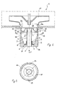
Figure 1 is a schematic axial section through apparatus equipped with an air-gas mixer device formed in accordance with the present invention, -
Figure 2 is a schematic view in partial section, taken on the line II-II ofFigure 1 , and -
Figure 3 is a view corresponding to that ofFigure 1 , of a variant of the invention. - With reference to the drawings mentioned, an air-gas mixer device formed in accordance with the invention, in particular for supplying a forced-ventilation burner (not shown), is generally indicated 1.
- The
device 1 comprises atubular body 2 with a cylindrical shell of axis X, and having twoopposite ends 2a, 2b. Afirst duct 3 for directing a flow of fuel gas into the mixer extends inside thetubular body 2, coaxially therewith, between theends 2a and 2b. A secondaxial duct 4 of annular cross-section is defined between thetubular body 2 and thefirst duct 3, for directing an air-flow admitted to thedevice 1 at the end 2a. - According to the invention, the flow admitted to the
duct 4 can be regulated by means of a choke element, generally indicated 5. Theelement 5 is movable axially along the axis X inside the second duct, between a first position and a second position in which a minimum annular cross-section and a maximum cross-section are defined for the air-flow admitted at the end 2a. More particularly, thechoke element 5 comprises a sleeve-like element 6 which is mounted for sliding on thefirst duct 3 and from an axial end of which a disc-shaped portion 7 extends radially. In the path of theelement 5 between the two above-mentioned positions, thesecond duct 4 has apart 8 which diverges in the direction of the flow so as to define, jointly with theportion 7, flow cross-sections which increase from the first position towards the second position. InFigure 1 , theelement 5 is shown in solid outline in the first position of minimum cross-section and in broken outline in the second, maximum-flow position. - Preferably, the
part 8 of theduct 4 and theportion 7 are axially symmetrical and thepart 8 has a preselected taper. - At the
end 2b, thedevice 1 further comprises a tubular section 9 disposed coaxially between the first andsecond ducts choke element 5, with reference to the direction the air and gas flow, indicated by the arrow F ofFigure 1 . - Advantageously, the tubular section 9 is connected axially to the first duct and has a
converging wall 10 which defines athird duct 11 having an annular cross-section extending outside the first duct. - The
wall 10 in turn defines afourth duct 12 disposed in an annular arrangement outside thethird duct 11 and communicating with the second duct through one or more radial openings 13 (two openings in the embodiment shown) provided in the outercylindrical shell 14 of the tubular section 9. The third andfourth ducts duct 4 into respective and distinct primary and secondary air-flows. - The shell of the second duct also has at least one
recess 15 formed in the inner surface of the duct and extending axially downstream of thepart 8 in a position facing theopenings 13 so as to form a passage for putting the second and fourth ducts into communication through the openings. The cylindrical shell advantageously has tworecesses 15 of equal circumferential extent and spaced apart uniformly. Thetubular body 2 is also fitted at least partially on the tubular section 9 so as to be movable rotatably relative to the section 9 about the axis X in order to constitute means for choking theopenings 13. More particularly, cylindrical shell portions, indicated 16, which are disposed betweenadjacent recesses 15, are movable away from and towards a position in which they are completely superimposed on theopenings 13, consequently closing them. - The circumferential extent of the
recesses 15 is selected in a manner such that theopenings 13 are closed or are fully open simultaneously as a result of the relative rotation between thetubular body 2 and the section 9. - A radial fan, indicated 17, disposed downstream of the
tubular body 2 in the direction of the air and/or gas flow, has an intake opening 17a extending in front of theoutlet end 2b from which the air/gas mixture emerges. Defined between thefan 17 and thetubular body 2 is amixing chamber 18 which is supplied by the above-describedducts - In use, the
mixer device 1 is suitable for applications in which thechoke element 5 is mounted with a vertical path, that is, applications in which the axis X is the axis along which the force of gravity acts. In this case, thechoke element 5 is subject to the gravitational force correlated with its own weight and to the pressures induced in theduct 4. - With a minimum-pressure signal produced by the minimum rate of revolution of the
fan 17 in suction, thechoke element 5 is moved vertically by its own weight to the first position (shown in solid outline inFigure 1 ) in which it is in abutment with anabutment element 19 extending radially in theduct 4. In this position, the minimum cross-section for the gas-flow admitted at the end 2a of theduct 4 is defined. - Upon an increase in the pressure-signal produced by an increase in the rate of revolution of the fan, the consequent reduction in pressure tends to move the
element 5 towards the second position (shown in broken outline inFigure 1 ), in opposition the effect of the gravitational force. In this position, the maximum cross-section for the air-flow is defined. Between the minimum and maximum positions, it is possible to define intermediate flow cross-sections each of which is obtained by equilibrium of the gravitational force and the pressure acting on thechoke element 5. The air-flow which is to be mixed with the gas-flow delivered through theduct 3 is thus modulated. - The flow is also separated into the primary and secondary air-flows directed through the
ducts choke element 5 in the second position) the secondary air-flow is directed through theopenings 13 and thefourth duct 12 into themixing chamber 18. The secondary air-flow can also be modulated by adjustment of the outflow cross-sections of theopenings 13, for example, by partial closure thereof. - It is thus possible to modulate the air-flow at the intake of the fan, extending the range of modulation in comparison with known applications.
- In a variant of the invention, shown in
Figure 3 , in which details similar to those of the previous embodiment are indicated by the same reference numerals, thechoke element 5 is urged resiliently into the first position (of minimum flow cross-section), for example, by aspring 20 fitted on thefirst duct 3 and having opposite ends acting on the tubular section 9 and on theelement 5, respectively. This variant of the invention is usable effectively in all applications in which theelement 5 is not subject to the force of gravity, for example, owing to horizontal mounting of themixer device 1. In this case, theelement 5 is subject to the pressures and to the resilient forces of thespring 20 along the axis X and the flow-modulation positions (including the minimum and maximum flow positions) are reached as a result of the equilibrium which is brought about between the above-mentioned forces acting on theelement 5. - The invention thus achieves the objects proposed, affording many advantages over known solutions.
- A first advantage is that, by virtue of the modulation of the flow which can be achieved with the device according to the invention, the flow-modulation range, and consequently the power range, is advantageously extended.
- A further advantage is that the maximum flow achieved with the modulation of the device according to the invention is further adjustable by selective modulation of the secondary air-flow.
- Yet another advantage is that the choke element according to the invention brings about pressure losses such as to reduce the effects of resonance and the consequent noise phenomena induced in the device.
- One of the chief advantages is greater axial and radial compactness of the device, by virtue of the fact that the means for choking the radial openings of the mixer are incorporated in the air-diverting duct.
Claims (15)
- An air-gas mixer device, particularly for gas burners with forced ventilation, comprising:- an air-gas mixing chamber (18) supplied by a gas-flow and by an air-flow which are directed in the device through a first duct (3) and a second duct (4), respectively, characterized in that it further comprises:- first means for choking the second duct (4) in order to choke the air-flow admitted to the mixer device through the second duct,- air-flow diverting means (9) for separating and directing the choked air-flow into a primary air-flow and a separate and distinct secondary air-flow, and- second choke means associated with the secondary air-flow so as to direct the secondary air-flow selectively towards the mixing chamber (18).
- A mixer device according to Claim 1 in which the first choke means comprise a choke element (5) movable axially inside the second duct (4) between a first position and a second position in which a minimum cross-section and a maximum cross-section for the air-flow admitted to the second duct (4) are defined, respectively.
- A mixer device according to Claim 2 in which the second duct (4) diverges in the direction of the air-flow, at least in a part extending in the region of the axial path of the choke element (5) between the first and second positions, so that the choke element (5) defines, jointly with the second duct (4), flow cross-sections in the second duct which increase from the first position towards the second position.
- A mixer device according to Claim 3 in which the first and second ducts (3, 4), as well as the choke element (5), are coaxial with one another.
- A mixer device according to any one of Claims 3 to 4 in which the choke element (5) and the second duct (4) are axially symmetrical, at least along the said part (8).
- A mixer device according to any one of Claims 2 to 5 in which the first gas duct (3) extends axially inside the second duct (4) and the choke element (5) is fitted slidably on the first duct (3).
- A mixer device according to any one of Claims 2 to 6 in which the choke element (5) comprises a disc-shaped portion (7) extending radially from a sleeve element (6), the sleeve element being associated slidably with the first duct (3).
- A mixer device according to any one of the preceding claims in which the diverting means comprise a tubular section (9) disposed coaxially between the first and second ducts (3, 4), downstream of the choke element (5) with reference to the direction of the air-flow, the tubular section (9) defining a third duct (11) which converges in the direction of the flow and which can divert the primary air-flow, as well as a fourth duct (12), communicating with the first duct (3) through one or more radial openings (13) which are associated with the second choke means and are provided in the tubular section (9), so as to direct the secondary air-flow selectively towards the mixing chamber (18).
- A mixer device according to Claim 8 in which the second duct (4) is at least partially fitted on the tubular section (9) in order to constitute means for choking the openings, the second duct (4) being movable rotatably on the tubular section (9) away from and towards a position in which the openings (13) are completely closed.
- A mixer device according to Claim 8 or Claim 9 in which the conveyor means comprise at least one axial passage defined between the second duct (4) and the tubular section (9) for putting the second and fourth ducts into communication through the one or more openings.
- A mixer device according to Claim 10 in which the at least one passage comprises a respective recess (15) which is provided in the inner surface of the second duct (4), extends for at least a circumferential portion of the cross-section of the duct, and is elongate axially in the duct in the region of the openings (13).
- A mixer device according to Claim 11 in which two angularly spaced-apart recesses (15) are provided, defining respective axial passages associated with two openings, the recesses having a circumferential extent such that the second duct and the tubular section are movable rotatably relative to one another between a position in which the openings are completely closed and a fully-open position in which the recesses are superimposed on the respective openings.
- A mixer device according to any one of the preceding claims in which the first choke means are urged resiliently towards the first operative position of minimum gas-flow cross-section.
- A mixer device according to Claim 13 in which a spring is provided, fitted on the first duct and having opposite ends acting on the tubular section and on the choke element.
- A mixer device according to any one of the preceding claims in which the mixing chamber is disposed in the region of an intake opening of a fan the output of which is connected to a gas burner.
Applications Claiming Priority (1)
| Application Number | Priority Date | Filing Date | Title |
|---|---|---|---|
| PCT/IT2002/000284 WO2003092875A2 (en) | 2002-04-30 | 2002-04-30 | An air-gas mixer device, particularly for gas burners and similar apparatus |
Publications (2)
| Publication Number | Publication Date |
|---|---|
| EP1499428A2 EP1499428A2 (en) | 2005-01-26 |
| EP1499428B1 true EP1499428B1 (en) | 2008-04-09 |
Family
ID=29287823
Family Applications (1)
| Application Number | Title | Priority Date | Filing Date |
|---|---|---|---|
| EP02733230A Expired - Lifetime EP1499428B1 (en) | 2002-04-30 | 2002-04-30 | An air-gas mixer device, particularly for gas burners and similar apparatus |
Country Status (5)
| Country | Link |
|---|---|
| EP (1) | EP1499428B1 (en) |
| CN (1) | CN1301383C (en) |
| AU (1) | AU2002306234B2 (en) |
| DE (1) | DE60226079D1 (en) |
| WO (1) | WO2003092875A2 (en) |
Families Citing this family (6)
| Publication number | Priority date | Publication date | Assignee | Title |
|---|---|---|---|---|
| DE102007022008B4 (en) * | 2007-05-08 | 2009-02-26 | Saia-Burgess Dresden Gmbh | Combined fan / gas valve unit |
| IT1395189B1 (en) * | 2009-07-22 | 2012-09-05 | Ln 2 Srl Socio Unico | AIR-GAS MIXER DEVICE, PARTICULARLY FOR PRE-MIXING BURNER APPLIANCES. |
| IT1402076B1 (en) * | 2010-09-02 | 2013-08-28 | Sit La Precisa Spa Con Socio Unico | AIR-GAS MIXER DEVICE FOR COMBUSTIBLE GAS BURNERS WITH PREMIXING |
| WO2019116407A1 (en) * | 2017-12-11 | 2019-06-20 | Sit S.P.A. | Valve delivery apparatus |
| US11441772B2 (en) | 2018-07-19 | 2022-09-13 | Brunswick Corporation | Forced-draft pre-mix burner device |
| DE102023207226A1 (en) | 2023-07-28 | 2025-01-30 | Robert Bosch Gesellschaft mit beschränkter Haftung | air-gas mixer, air-gas mixing unit and air-gas mixture combustion plant |
Family Cites Families (5)
| Publication number | Priority date | Publication date | Assignee | Title |
|---|---|---|---|---|
| FR2464433A1 (en) * | 1979-08-31 | 1981-03-06 | Elf Aquitaine | AIR GAS BURNER WITH VERY HIGH FLOW VARIATION |
| DE4101260A1 (en) * | 1991-01-17 | 1992-07-23 | Ruhrgas Ag | ACTUATOR FOR THE TWO-STAGE POWER CONTROL OF GAS BLOWING BURNERS |
| CN2155497Y (en) * | 1993-04-06 | 1994-02-09 | 张泮辉 | Mixer for automatic regulating gas proportion |
| CN2237781Y (en) * | 1995-08-18 | 1996-10-16 | 王毓奎 | Multifunctional flame-change burner |
| IT1302544B1 (en) * | 1998-12-28 | 2000-09-05 | Sit La Precisa S R L Ora Sit L | PILOT BURNER FOR PERFECTED GAS. |
-
2002
- 2002-04-30 EP EP02733230A patent/EP1499428B1/en not_active Expired - Lifetime
- 2002-04-30 CN CNB028288459A patent/CN1301383C/en not_active Expired - Fee Related
- 2002-04-30 AU AU2002306234A patent/AU2002306234B2/en not_active Expired - Fee Related
- 2002-04-30 WO PCT/IT2002/000284 patent/WO2003092875A2/en not_active Ceased
- 2002-04-30 DE DE60226079T patent/DE60226079D1/en not_active Expired - Lifetime
Also Published As
| Publication number | Publication date |
|---|---|
| AU2002306234B2 (en) | 2008-03-06 |
| CN1301383C (en) | 2007-02-21 |
| DE60226079D1 (en) | 2008-05-21 |
| AU2002306234A1 (en) | 2003-11-17 |
| WO2003092875A2 (en) | 2003-11-13 |
| EP1499428A2 (en) | 2005-01-26 |
| CN1625670A (en) | 2005-06-08 |
| WO2003092875A3 (en) | 2004-02-19 |
Similar Documents
| Publication | Publication Date | Title |
|---|---|---|
| EP1356234B1 (en) | An improved air-gas mixer device | |
| EP2286149B1 (en) | Premix gas burner | |
| JP3789935B2 (en) | Atmospheric gas burner with extended turndown | |
| US3486834A (en) | Gas burning system arrangement | |
| EP0504302A1 (en) | Burner construction and method of making the same | |
| US11530814B2 (en) | Adjustable restrictor for burner | |
| KR20010070378A (en) | Flame stabilizing channel for increased turn down of gas burners | |
| CA1303102C (en) | Pistol grip type compressed air blower | |
| CN101688618A (en) | Adjusting device | |
| NZ270773A (en) | Gas burner flame stability provided by pilot port adjacent to burner ports and having high flow resistance for a stable reignition source | |
| AU2002306234B2 (en) | An air-gas mixer device, particulary for gas burners and similar apparatus | |
| WO2017029772A1 (en) | Combustion device | |
| KR200497783Y1 (en) | Mixing device for gas burners | |
| US4177970A (en) | Valve assembly for use in an air distribution system | |
| CA2582031A1 (en) | A splitter valve | |
| US11603851B2 (en) | Draft inducer blower | |
| US3820943A (en) | Power burner | |
| EP0614045A1 (en) | Method and device for feeding air-gas-mixtures at various flow rates to a premix burner | |
| GB2272510A (en) | Combustion chamber housing assembly for a gas turbine | |
| EP0697563A1 (en) | Gas boiler valve assembly | |
| HU9903850D0 (en) | Device for regulating the combustion air flow rate in a wall-mounted boiler | |
| KR100428956B1 (en) | Air volume proportion control valve of gas boiler | |
| US1205265A (en) | Sad-iron. | |
| CA2555855C (en) | Vent assembly for combustion gases generated by an appliance | |
| KR200237292Y1 (en) | A gas burner for gas-air ratio controls |
Legal Events
| Date | Code | Title | Description |
|---|---|---|---|
| PUAI | Public reference made under article 153(3) epc to a published international application that has entered the european phase |
Free format text: ORIGINAL CODE: 0009012 |
|
| 17P | Request for examination filed |
Effective date: 20041008 |
|
| AK | Designated contracting states |
Kind code of ref document: A2 Designated state(s): AT BE CH CY DE DK ES FI FR GB GR IE IT LI LU MC NL PT SE TR |
|
| AX | Request for extension of the european patent |
Extension state: AL LT LV MK RO SI |
|
| GRAP | Despatch of communication of intention to grant a patent |
Free format text: ORIGINAL CODE: EPIDOSNIGR1 |
|
| GRAS | Grant fee paid |
Free format text: ORIGINAL CODE: EPIDOSNIGR3 |
|
| GRAA | (expected) grant |
Free format text: ORIGINAL CODE: 0009210 |
|
| AK | Designated contracting states |
Kind code of ref document: B1 Designated state(s): DE FR GB IT NL |
|
| REG | Reference to a national code |
Ref country code: GB Ref legal event code: FG4D |
|
| REF | Corresponds to: |
Ref document number: 60226079 Country of ref document: DE Date of ref document: 20080521 Kind code of ref document: P |
|
| NLV1 | Nl: lapsed or annulled due to failure to fulfill the requirements of art. 29p and 29m of the patents act | ||
| PG25 | Lapsed in a contracting state [announced via postgrant information from national office to epo] |
Ref country code: NL Free format text: LAPSE BECAUSE OF FAILURE TO SUBMIT A TRANSLATION OF THE DESCRIPTION OR TO PAY THE FEE WITHIN THE PRESCRIBED TIME-LIMIT Effective date: 20080409 Ref country code: DE Free format text: LAPSE BECAUSE OF FAILURE TO SUBMIT A TRANSLATION OF THE DESCRIPTION OR TO PAY THE FEE WITHIN THE PRESCRIBED TIME-LIMIT Effective date: 20080710 |
|
| EN | Fr: translation not filed | ||
| PLBE | No opposition filed within time limit |
Free format text: ORIGINAL CODE: 0009261 |
|
| STAA | Information on the status of an ep patent application or granted ep patent |
Free format text: STATUS: NO OPPOSITION FILED WITHIN TIME LIMIT |
|
| 26N | No opposition filed |
Effective date: 20090112 |
|
| GBPC | Gb: european patent ceased through non-payment of renewal fee |
Effective date: 20080709 |
|
| PG25 | Lapsed in a contracting state [announced via postgrant information from national office to epo] |
Ref country code: FR Free format text: LAPSE BECAUSE OF FAILURE TO SUBMIT A TRANSLATION OF THE DESCRIPTION OR TO PAY THE FEE WITHIN THE PRESCRIBED TIME-LIMIT Effective date: 20090130 |
|
| PG25 | Lapsed in a contracting state [announced via postgrant information from national office to epo] |
Ref country code: GB Free format text: LAPSE BECAUSE OF NON-PAYMENT OF DUE FEES Effective date: 20080709 |
|
| PG25 | Lapsed in a contracting state [announced via postgrant information from national office to epo] |
Ref country code: IT Free format text: LAPSE BECAUSE OF FAILURE TO SUBMIT A TRANSLATION OF THE DESCRIPTION OR TO PAY THE FEE WITHIN THE PRESCRIBED TIME-LIMIT Effective date: 20080409 |