EP1499081A2 - Multicarrier signal structure - Google Patents
Multicarrier signal structure Download PDFInfo
- Publication number
- EP1499081A2 EP1499081A2 EP04012801A EP04012801A EP1499081A2 EP 1499081 A2 EP1499081 A2 EP 1499081A2 EP 04012801 A EP04012801 A EP 04012801A EP 04012801 A EP04012801 A EP 04012801A EP 1499081 A2 EP1499081 A2 EP 1499081A2
- Authority
- EP
- European Patent Office
- Prior art keywords
- tones
- physical layer
- data
- ieee
- digital
- Prior art date
- Legal status (The legal status is an assumption and is not a legal conclusion. Google has not performed a legal analysis and makes no representation as to the accuracy of the status listed.)
- Withdrawn
Links
Images


Classifications
-
- H—ELECTRICITY
- H04—ELECTRIC COMMUNICATION TECHNIQUE
- H04L—TRANSMISSION OF DIGITAL INFORMATION, e.g. TELEGRAPHIC COMMUNICATION
- H04L5/00—Arrangements affording multiple use of the transmission path
- H04L5/003—Arrangements for allocating sub-channels of the transmission path
- H04L5/0044—Allocation of payload; Allocation of data channels, e.g. PDSCH or PUSCH
- H04L5/0046—Determination of the number of bits transmitted on different sub-channels
-
- H—ELECTRICITY
- H04—ELECTRIC COMMUNICATION TECHNIQUE
- H04L—TRANSMISSION OF DIGITAL INFORMATION, e.g. TELEGRAPHIC COMMUNICATION
- H04L27/00—Modulated-carrier systems
- H04L27/26—Systems using multi-frequency codes
- H04L27/2601—Multicarrier modulation systems
- H04L27/2602—Signal structure
-
- H—ELECTRICITY
- H04—ELECTRIC COMMUNICATION TECHNIQUE
- H04L—TRANSMISSION OF DIGITAL INFORMATION, e.g. TELEGRAPHIC COMMUNICATION
- H04L27/00—Modulated-carrier systems
- H04L27/26—Systems using multi-frequency codes
- H04L27/2601—Multicarrier modulation systems
- H04L27/2602—Signal structure
- H04L27/261—Details of reference signals
-
- H—ELECTRICITY
- H04—ELECTRIC COMMUNICATION TECHNIQUE
- H04L—TRANSMISSION OF DIGITAL INFORMATION, e.g. TELEGRAPHIC COMMUNICATION
- H04L5/00—Arrangements affording multiple use of the transmission path
- H04L5/003—Arrangements for allocating sub-channels of the transmission path
- H04L5/0048—Allocation of pilot signals, i.e. of signals known to the receiver
-
- H—ELECTRICITY
- H04—ELECTRIC COMMUNICATION TECHNIQUE
- H04L—TRANSMISSION OF DIGITAL INFORMATION, e.g. TELEGRAPHIC COMMUNICATION
- H04L27/00—Modulated-carrier systems
- H04L27/26—Systems using multi-frequency codes
- H04L27/2601—Multicarrier modulation systems
- H04L27/2602—Signal structure
- H04L27/2605—Symbol extensions, e.g. Zero Tail, Unique Word [UW]
-
- H—ELECTRICITY
- H04—ELECTRIC COMMUNICATION TECHNIQUE
- H04L—TRANSMISSION OF DIGITAL INFORMATION, e.g. TELEGRAPHIC COMMUNICATION
- H04L27/00—Modulated-carrier systems
- H04L27/26—Systems using multi-frequency codes
- H04L27/2601—Multicarrier modulation systems
- H04L27/2602—Signal structure
- H04L27/2605—Symbol extensions, e.g. Zero Tail, Unique Word [UW]
- H04L27/2607—Cyclic extensions
-
- H—ELECTRICITY
- H04—ELECTRIC COMMUNICATION TECHNIQUE
- H04L—TRANSMISSION OF DIGITAL INFORMATION, e.g. TELEGRAPHIC COMMUNICATION
- H04L27/00—Modulated-carrier systems
- H04L27/26—Systems using multi-frequency codes
- H04L27/2601—Multicarrier modulation systems
- H04L27/2626—Arrangements specific to the transmitter only
- H04L27/2627—Modulators
- H04L27/2628—Inverse Fourier transform modulators, e.g. inverse fast Fourier transform [IFFT] or inverse discrete Fourier transform [IDFT] modulators
-
- H—ELECTRICITY
- H04—ELECTRIC COMMUNICATION TECHNIQUE
- H04L—TRANSMISSION OF DIGITAL INFORMATION, e.g. TELEGRAPHIC COMMUNICATION
- H04L5/00—Arrangements affording multiple use of the transmission path
- H04L5/0001—Arrangements for dividing the transmission path
- H04L5/0003—Two-dimensional division
- H04L5/0005—Time-frequency
- H04L5/0007—Time-frequency the frequencies being orthogonal, e.g. OFDM(A) or DMT
-
- H—ELECTRICITY
- H04—ELECTRIC COMMUNICATION TECHNIQUE
- H04L—TRANSMISSION OF DIGITAL INFORMATION, e.g. TELEGRAPHIC COMMUNICATION
- H04L5/00—Arrangements affording multiple use of the transmission path
- H04L5/0001—Arrangements for dividing the transmission path
- H04L5/0014—Three-dimensional division
- H04L5/0023—Time-frequency-space
Definitions
- FIG. 2 is a schematic block diagram illustrating a wireless device constructed according to the present invention.
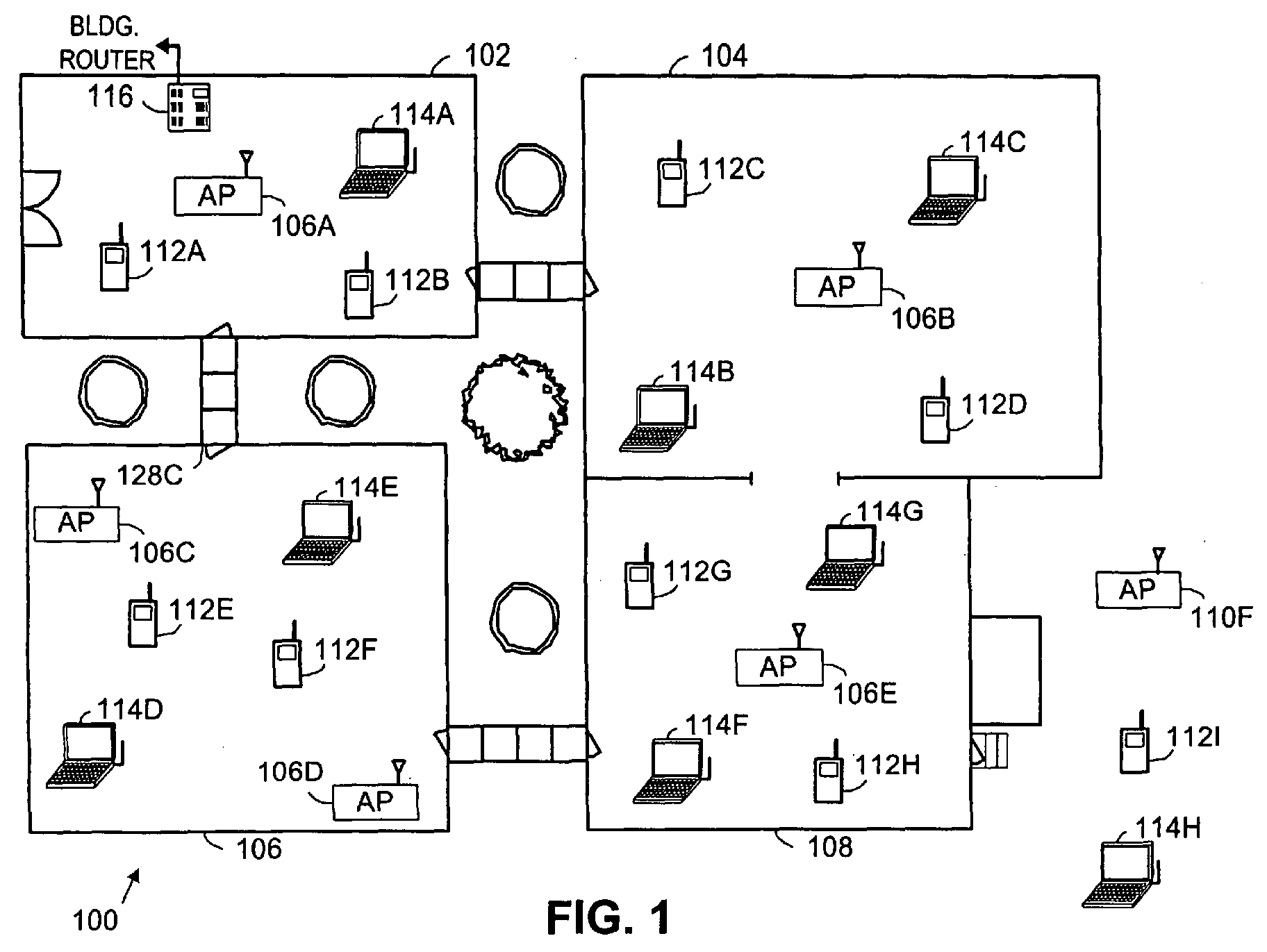
- FIG. 2 is representative of any of the wireless telephones/data terminals 112A-112I and/or laptop computers 114A-114H of FIG. 1. Functionality is divided between a host device 18 and a radio 60.
- the host device 18 is actually the laptop computer and the radio 60 is an expansion card or an expansion device that services the wireless communication needs of the host device 18.
- the telephones 112A-112I the host device 18 and the radio 60 are both contained within the case of the telephone.
- the digital-to-analog converter 78 converts the digital transmission formatted data 96 from the digital domain to the analog domain.
- the filtering/gain module 80 filters and/or adjusts the gain of the analog signal prior to providing it to the IF mixing stage 82.
- the IF mixing stage 82 directly converts the analog baseband or low IF signal into an RF signal based on a transmitter local oscillation 83 provided by local oscillation module 74.
- the power amplifier 84 amplifies the RF signal to produce outbound RF signal 98, which is filtered by the transmitter filter module 85.
- the antenna 86 transmits the outbound RF signal 98 to a targeted device such as a base station, an access point and/or another wireless communication device.
- the radio 60 also receives an inbound RF signal 88 via the antenna 86, which was transmitted by a base station, an access point, or another wireless communication device.
- the antenna 86 provides the inbound RF signal 88 to the receiver filter module 71 via the Tx/Rx switch 77, where the Rx filter 71 bandpass filters the inbound RF signal 88.
- the Rx filter 71 provides the filtered RF signal to low noise amplifier 72, which amplifies the signal 88 to produce an amplified inbound RF signal.
- the low noise amplifier 72 provides the amplified inbound RF signal to the IF mixing module 70, which directly converts the amplified inbound RF signal into an inbound low IF signal or baseband signal based on a receiver local oscillation 81 provided by local oscillation module 74.
- the down conversion module 70 provides the inbound low IF signal or baseband signal to the filtering/gain module 68.
- the filtering/gain module 68 filters and/or gains the inbound low IF signal or the inbound baseband signal to produce a filtered inbound signal.
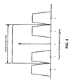
- FIG. 4 is a graph illustrating the manner in which tones of the physical layer are managed according to an embodiment of the present invention. Because the bandwidth of the physical layer is reduced (as compared to the bandwidth of the IEEE 802.11(a) physical layer), the center tones, tone -1 and tone +1 are nearer DC. Many receiver designs incorporate a notch filter at DC. Normal frequency offset between supported mobile terminals effectively moves this notch away from DC. With the closer tone spacing, the effect of frequency offset is more severe. In a most severe operating condition, frequency offset may cause the notch filter to remove a portion of either tone -1 or tone +1.
Landscapes
- Engineering & Computer Science (AREA)
- Signal Processing (AREA)
- Computer Networks & Wireless Communication (AREA)
- Mobile Radio Communication Systems (AREA)
- Stereo-Broadcasting Methods (AREA)
Abstract
Description
- k = 0; data on tones {-21, -7} k = 1; {-21, 7}
- k = 2; {-21, 21} k = 3; {-7,7}
- k = 4; {-7, 21} k = 5; {7, 21}
- aCCATime increases from 4 to 8 microseconds
- aAirPropagationTime increases from « 1 microsecond to 2 microseconds
- aSlotTIME = 14 microseconds
- aSIFSTIME = 16 microseconds (no change)
- PIFS = 30 microseconds (SIFS + SLOT)
- DIFS = 44 microseconds (SIFS + 2*SLOT)
Claims (6)
- An Orthogonal Frequency Division Multiplex (OFDM) baseband physical layer comprising:wherein at least two tones adjacent DC are not used, and wherein data that would be carried on such tones is multiplexed with pilot tones on other of the plurality of tones; anda plurality of tones symmetrically spaced about DC;a tone spacing of approximately 0.15625 MHz;
wherein by not using the at least two tones adjacent DC, frequency offset and notch filtering problems are overcome. - The OFDM baseband physical layer of claim 1, wherein the physical layer alternates the tones used to carry the data that would otherwise be carried on two tones adjacent DC according to k = symbol index mod 6 (starting from SIGNAL symbol as zero):k = 0; data on tones {-21, -7};k = 1; data on tones {-21, 7};k = 2; data on tones {-21, 21};k = 3; data on tones {-7,7};k = 4; data on tones {-7, 21}; andk = 5; data on tones {7, 21}.
- The OFDM baseband physical layer of claim 1, wherein the receiver bandwidth is reduced by a factor of two and the SNR of the physical layer is improved by 3 dB as compared to the IEEE 802.11(a) physical layer.
- The OFDM baseband physical layer of claim 1, wherein the length of the guard interval (cyclical prefix) is doubled to 1.6 microseconds as compared to the IEEE 802.11(a) physical layer.
- The OFDM baseband physical layer of claim 1, wherein the symbol length is doubled to maintain the same amount of guard interval overhead as the IEEE 802.11 (a) physical layer.
- The OFDM baseband physical layer of claim 1, wherein a 64 point Fast Fourier Transform (FFT) is used with the physical layer.
Applications Claiming Priority (2)
| Application Number | Priority Date | Filing Date | Title |
|---|---|---|---|
| US48853103P | 2003-07-18 | 2003-07-18 | |
| US488531P | 2003-07-18 |
Publications (2)
| Publication Number | Publication Date |
|---|---|
| EP1499081A2 true EP1499081A2 (en) | 2005-01-19 |
| EP1499081A3 EP1499081A3 (en) | 2007-01-03 |
Family
ID=33477010
Family Applications (1)
| Application Number | Title | Priority Date | Filing Date |
|---|---|---|---|
| EP04012801A Withdrawn EP1499081A3 (en) | 2003-07-18 | 2004-05-28 | Multicarrier signal structure |
Country Status (2)
| Country | Link |
|---|---|
| US (1) | US20050013238A1 (en) |
| EP (1) | EP1499081A3 (en) |
Cited By (2)
| Publication number | Priority date | Publication date | Assignee | Title |
|---|---|---|---|---|
| EP1533967A3 (en) * | 2003-11-20 | 2006-12-27 | Fujitsu Limited | Transmitting methods and transmitting apparatuses |
| WO2008137657A1 (en) * | 2007-05-07 | 2008-11-13 | Interdigital Technology Corporation | Orthogonal hadamard code based secondary synchronization channel |
Families Citing this family (37)
| Publication number | Priority date | Publication date | Assignee | Title |
|---|---|---|---|---|
| US7418042B2 (en) | 2003-09-17 | 2008-08-26 | Atheros Communications, Inc. | Repetition coding for a wireless system |
| JP4212548B2 (en) | 2003-12-26 | 2009-01-21 | 株式会社東芝 | Wireless transmission device, wireless reception device, wireless transmission method, and wireless reception method |
| US7885178B2 (en) | 2003-12-29 | 2011-02-08 | Intel Corporation | Quasi-parallel multichannel receivers for wideband orthogonal frequency division multiplexed communications and associated methods |
| US8059740B2 (en) * | 2004-02-19 | 2011-11-15 | Broadcom Corporation | WLAN transmitter having high data throughput |
| US7742533B2 (en) | 2004-03-12 | 2010-06-22 | Kabushiki Kaisha Toshiba | OFDM signal transmission method and apparatus |
| JP4647220B2 (en) * | 2004-03-24 | 2011-03-09 | 日立プラズマディスプレイ株式会社 | Driving method of plasma display device |
| US8619907B2 (en) * | 2004-06-10 | 2013-12-31 | Agere Systems, LLC | Method and apparatus for preamble training in a multiple antenna communication system |
| EP3537681B1 (en) | 2004-06-24 | 2020-10-07 | Apple Inc. | Preambles in ofdma system |
| JP4597193B2 (en) * | 2004-07-07 | 2010-12-15 | サムスン エレクトロニクス カンパニー リミテッド | Apparatus and method for transmitting pilot signal in broadband wireless access communication system using multiple transmit antennas |
| KR100856249B1 (en) * | 2004-08-26 | 2008-09-03 | 삼성전자주식회사 | Initial Operation Mode Detection Method in Wireless Communication System |
| US7593472B2 (en) * | 2004-10-22 | 2009-09-22 | Integrated System Solution Corp. | Methods and apparatus for circulation transmissions for OFDM-based MIMO systems |
| US8472889B2 (en) * | 2005-04-04 | 2013-06-25 | Broadcom Corporation | Radio frequency transceiver integrated circuit floor plan applicable to MIMO |
| EP2173075B1 (en) * | 2005-04-29 | 2013-06-05 | Sony Deutschland GmbH | Receiving device and communication method for an OFDM communication system with a new preamble structure |
| USRE47633E1 (en) | 2005-06-22 | 2019-10-01 | Odyssey Wireless Inc. | Systems/methods of conducting a financial transaction using a smartphone |
| US8233554B2 (en) | 2010-03-29 | 2012-07-31 | Eices Research, Inc. | Increased capacity communications for OFDM-based wireless communications systems/methods/devices |
| US7876845B2 (en) * | 2005-06-22 | 2011-01-25 | Eices Research, Inc. | Wireless communications systems and/or methods providing low interference, high privacy and/or cognitive flexibility |
| US8670493B2 (en) | 2005-06-22 | 2014-03-11 | Eices Research, Inc. | Systems and/or methods of increased privacy wireless communications |
| EP1793549B1 (en) | 2005-12-02 | 2008-10-15 | Alcatel Lucent | Digital receiver for FDM signals |
| EP1793550B1 (en) * | 2005-12-02 | 2008-10-22 | Alcatel Lucent | Multi-carrier signals with selectable pilot pattern |
| US8014479B2 (en) * | 2005-12-22 | 2011-09-06 | Delphi Technologies, Inc. | Method and system for communicating sub-synchronization signals using a phase rotator |
| US20070147532A1 (en) * | 2005-12-22 | 2007-06-28 | Dibiaso Eric A | Method and system for injecting sub-synchronization signals |
| US8391131B2 (en) * | 2006-02-03 | 2013-03-05 | Telefonaktiebolaget L M Ericsson (Publ) | Method for processing the random access transmission in the frequency domain |
| US7974176B2 (en) * | 2006-02-28 | 2011-07-05 | Atc Technologies, Llc | Systems, methods and transceivers for wireless communications over discontiguous spectrum segments |
| KR100821938B1 (en) * | 2006-04-14 | 2008-04-15 | 삼성전자주식회사 | Device and method for estimating uplink frequency offset in wireless communication system |
| US8189621B2 (en) | 2006-05-12 | 2012-05-29 | Microsoft Corporation | Stack signaling to application with lack of requested bandwidth |
| US8144793B2 (en) | 2006-12-12 | 2012-03-27 | Microsoft Corporation | Cognitive multi-user OFDMA |
| US7929623B2 (en) * | 2007-03-30 | 2011-04-19 | Microsoft Corporation | FEC in cognitive multi-user OFDMA |
| US20080273600A1 (en) * | 2007-05-01 | 2008-11-06 | Samsung Electronics Co., Ltd. | Method and apparatus of wireless communication of uncompressed video having channel time blocks |
| US7970085B2 (en) | 2007-05-08 | 2011-06-28 | Microsoft Corporation | OFDM transmission and reception for non-OFDMA signals |
| US9313067B2 (en) * | 2007-08-14 | 2016-04-12 | Qualcomm Incorporated | Multi-bandwidth communication system using a shared baseband processor |
| US8837435B2 (en) * | 2007-10-31 | 2014-09-16 | Samsung Electronics Co., Ltd. | Method and system for medium access control in communication networks |
| US8374130B2 (en) | 2008-01-25 | 2013-02-12 | Microsoft Corporation | Orthogonal frequency division multiple access with carrier sense |
| US9374746B1 (en) | 2008-07-07 | 2016-06-21 | Odyssey Wireless, Inc. | Systems/methods of spatial multiplexing |
| US8811420B2 (en) * | 2009-01-05 | 2014-08-19 | Samsung Electronics Co., Ltd. | System and method for contention-based channel access for peer-to-peer connection in wireless networks |
| US9806790B2 (en) | 2010-03-29 | 2017-10-31 | Odyssey Wireless, Inc. | Systems/methods of spectrally efficient communications |
| US9048936B2 (en) * | 2012-01-02 | 2015-06-02 | Qualcomm Incorporated | Systems and methods for managing on-time of wireless receivers |
| US20170142721A1 (en) * | 2015-11-12 | 2017-05-18 | Intel Corporation | Apparatus, system and method of communicating over a narrowband channel in a 2.4 gigahertz (ghz) frequency band |
Family Cites Families (14)
| Publication number | Priority date | Publication date | Assignee | Title |
|---|---|---|---|---|
| US7274652B1 (en) * | 2000-06-02 | 2007-09-25 | Conexant, Inc. | Dual packet configuration for wireless communications |
| JP3024524B2 (en) * | 1995-09-25 | 2000-03-21 | 日本電気株式会社 | Carrier synchronization unit and synchronization method |
| JP3377389B2 (en) * | 1997-01-10 | 2003-02-17 | 株式会社鷹山 | Signal receiving method and apparatus in spread spectrum wireless communication system |
| KR100224863B1 (en) * | 1997-08-20 | 1999-10-15 | 윤종용 | Equalization Methods and Equalizers for OFDM Receivers |
| JP2001069117A (en) * | 1999-08-31 | 2001-03-16 | Matsushita Electric Ind Co Ltd | OFDM communication apparatus and propagation path estimation method |
| US6650617B1 (en) * | 2000-02-22 | 2003-11-18 | Thomson Licensing S.A. | Reduced complexity FFT window synchronization for an orthogonal frequency division multiplexing system |
| DE60031105T2 (en) * | 2000-07-06 | 2007-04-05 | Sony Deutschland Gmbh | Method and apparatus for providing uplink IFDM with time-frequency interleaving |
| US6985434B2 (en) * | 2000-09-01 | 2006-01-10 | Nortel Networks Limited | Adaptive time diversity and spatial diversity for OFDM |
| US20020065047A1 (en) * | 2000-11-30 | 2002-05-30 | Moose Paul H. | Synchronization, channel estimation and pilot tone tracking system |
| US6633616B2 (en) * | 2001-02-21 | 2003-10-14 | Magis Networks, Inc. | OFDM pilot tone tracking for wireless LAN |
| EP1267513A3 (en) * | 2001-06-11 | 2006-07-26 | Unique Broadband Systems, Inc. | Multiplexing of multicarrier signals |
| US7103116B2 (en) * | 2001-09-24 | 2006-09-05 | Atheros Communications, Inc. | Detection of a false detection of a communication packet |
| US7248559B2 (en) * | 2001-10-17 | 2007-07-24 | Nortel Networks Limited | Scattered pilot pattern and channel estimation method for MIMO-OFDM systems |
| DE10248507A1 (en) * | 2002-10-11 | 2004-04-22 | IHP GmbH - Innovations for High Performance Microelectronics/Institut für innovative Mikroelektronik | Error correction method for multiplex signals, esp. OFDM in digital audio broadcast (DAB), involves compensating or balancing step of partial elimination of phase error accumulation of part signal |
-
2004
- 2004-05-28 EP EP04012801A patent/EP1499081A3/en not_active Withdrawn
- 2004-07-16 US US10/892,626 patent/US20050013238A1/en not_active Abandoned
Cited By (3)
| Publication number | Priority date | Publication date | Assignee | Title |
|---|---|---|---|---|
| EP1533967A3 (en) * | 2003-11-20 | 2006-12-27 | Fujitsu Limited | Transmitting methods and transmitting apparatuses |
| US7471730B2 (en) | 2003-11-20 | 2008-12-30 | Fujitsu Limited | Transmitting method and transmitting apparatus |
| WO2008137657A1 (en) * | 2007-05-07 | 2008-11-13 | Interdigital Technology Corporation | Orthogonal hadamard code based secondary synchronization channel |
Also Published As
| Publication number | Publication date |
|---|---|
| EP1499081A3 (en) | 2007-01-03 |
| US20050013238A1 (en) | 2005-01-20 |
Similar Documents
| Publication | Publication Date | Title |
|---|---|---|
| US20050013238A1 (en) | OFDM frame formatting | |
| US8929317B2 (en) | Transmission of wide bandwidth signals in a network having legacy devices | |
| US8948064B2 (en) | Method and apparatus for long range private broadband wireless communication system | |
| US8891642B2 (en) | Mixed mode preamble for MIMO wireless communications | |
| TWI427979B (en) | Method and system for transmission of orthogonal frequency division multiplexed(ofdm)symbols in subframes | |
| US9300511B2 (en) | Method and apparatus for improving throughput of 5 MHZ WLAN transmissions | |
| EP3272087B1 (en) | System and method of waveform design for operation bandwidth extension | |
| US20150372849A1 (en) | Systems and methods for improvements to training field design for increased symbol durations | |
| US7689228B2 (en) | Method and apparatus for providing in-band wireless backhaul | |
| US12610399B2 (en) | Access point and communication method | |
| US9455845B2 (en) | Wireless communications apparatus | |
| EP1603277A1 (en) | Signaling format for WLANs | |
| KR20050117587A (en) | Fixed ofdm wireless man utilizing cpe having internal antenna | |
| KR20090035610A (en) | Devices, methods and systems for ultra wide band stand-alone repeaters / selectors | |
| US8477594B2 (en) | Backward-compatible long training sequences for wireless communication networks | |
| EP1566944B1 (en) | Wireless communication between stations of differing protocols | |
| EP1714453B1 (en) | Conveying additional signaling information in an ofdm-based wireless local area network | |
| CN100353698C (en) | Configuring a mimo communication | |
| WO2015099804A1 (en) | Methods and arrangements to estimate carrier frequency offset | |
| EP1501251A2 (en) | Frame structure for multicarrier transmission | |
| CN100502376C (en) | Device and method for generating OFDM frames in wireless communication | |
| US20060223453A1 (en) | Frequency shifted wireless local area network system |
Legal Events
| Date | Code | Title | Description |
|---|---|---|---|
| PUAI | Public reference made under article 153(3) epc to a published international application that has entered the european phase |
Free format text: ORIGINAL CODE: 0009012 |
|
| AK | Designated contracting states |
Kind code of ref document: A2 Designated state(s): AT BE BG CH CY CZ DE DK EE ES FI FR GB GR HU IE IT LI LU MC NL PL PT RO SE SI SK TR |
|
| AX | Request for extension of the european patent |
Extension state: AL HR LT LV MK |
|
| PUAL | Search report despatched |
Free format text: ORIGINAL CODE: 0009013 |
|
| AK | Designated contracting states |
Kind code of ref document: A3 Designated state(s): AT BE BG CH CY CZ DE DK EE ES FI FR GB GR HU IE IT LI LU MC NL PL PT RO SE SI SK TR |
|
| AX | Request for extension of the european patent |
Extension state: AL HR LT LV MK |
|
| RAP1 | Party data changed (applicant data changed or rights of an application transferred) |
Owner name: BROADCOM CORPORATION |
|
| 17P | Request for examination filed |
Effective date: 20070703 |
|
| AKX | Designation fees paid |
Designated state(s): DE FR GB |
|
| 17Q | First examination report despatched |
Effective date: 20071010 |
|
| GRAP | Despatch of communication of intention to grant a patent |
Free format text: ORIGINAL CODE: EPIDOSNIGR1 |
|
| STAA | Information on the status of an ep patent application or granted ep patent |
Free format text: STATUS: THE APPLICATION IS DEEMED TO BE WITHDRAWN |
|
| 18D | Application deemed to be withdrawn |
Effective date: 20111201 |