EP1499008A2 - Method and control system for electronic commutation of brushless DC motors - Google Patents
Method and control system for electronic commutation of brushless DC motors Download PDFInfo
- Publication number
- EP1499008A2 EP1499008A2 EP04011481A EP04011481A EP1499008A2 EP 1499008 A2 EP1499008 A2 EP 1499008A2 EP 04011481 A EP04011481 A EP 04011481A EP 04011481 A EP04011481 A EP 04011481A EP 1499008 A2 EP1499008 A2 EP 1499008A2
- Authority
- EP
- European Patent Office
- Prior art keywords
- winding
- current
- rotor
- motor
- currents
- Prior art date
- Legal status (The legal status is an assumption and is not a legal conclusion. Google has not performed a legal analysis and makes no representation as to the accuracy of the status listed.)
- Granted
Links
Images

Classifications
-
- H—ELECTRICITY
- H02—GENERATION; CONVERSION OR DISTRIBUTION OF ELECTRIC POWER
- H02P—CONTROL OR REGULATION OF ELECTRIC MOTORS, ELECTRIC GENERATORS OR DYNAMO-ELECTRIC CONVERTERS; CONTROLLING TRANSFORMERS, REACTORS OR CHOKE COILS
- H02P6/00—Arrangements for controlling synchronous motors or other dynamo-electric motors using electronic commutation dependent on the rotor position; Electronic commutators therefor
- H02P6/10—Arrangements for controlling torque ripple, e.g. providing reduced torque ripple
-
- H—ELECTRICITY
- H02—GENERATION; CONVERSION OR DISTRIBUTION OF ELECTRIC POWER
- H02P—CONTROL OR REGULATION OF ELECTRIC MOTORS, ELECTRIC GENERATORS OR DYNAMO-ELECTRIC CONVERTERS; CONTROLLING TRANSFORMERS, REACTORS OR CHOKE COILS
- H02P6/00—Arrangements for controlling synchronous motors or other dynamo-electric motors using electronic commutation dependent on the rotor position; Electronic commutators therefor
- H02P6/14—Electronic commutators
- H02P6/16—Circuit arrangements for detecting position
- H02P6/18—Circuit arrangements for detecting position without separate position detecting elements
- H02P6/182—Circuit arrangements for detecting position without separate position detecting elements using back-emf in windings
Definitions
- the present invention relates to a method for commutating a brushless DC motor according to the preamble of claim 1 and a corresponding control system according to the preamble of claim 16. Further relates the invention also includes a brushless DC motor for commutating the method according to the invention is equipped with such a control system.
- Permanently excited, electronically commutated DC motors are used today for many applications because compared to motors which have mechanical commutators (brushes), by avoiding wear parts (commutator, brushes, slip rings) even without special maintenance measures have a high life expectancy. moreover Such permanent-magnet motors are characterized by good efficiency and efficiency high energy density. An important area of application of such EC motors are Fans in which quiet operation is playing an increasingly important role. In this regard, known motor designs and commutation are still in need of improvement.
- Such an EC motor typically has an approximately trapezoidal Air gap induction.
- the commutation electronics of a three-speed motor consists from a semiconductor bridge with six electronic switching elements (transistors). In a conventional block commutation these are pairwise so switched on that a magnetic stator rotating field is generated. This results six possible switching states, which alternate periodically.
- the speed of the Motors can be controlled by the effective motor voltage. This will either the supply voltage, the so-called DC link voltage, changed, or it is one of the two conductive transistors pulse-width modulated clocked (PWM).
- PWM pulse-width modulated clocked
- a favorable solution offers a likewise known sensorless rotor position detection.
- sensorless means that no sensors as separate components are provided to detect mechanical variables directly. Rather, for an indirect detection of the rotor position uses only electrically measurable quantities.
- EP 1 104 087 A2 describes measures for controlling a DC motor, where a sinusoidal voltage / current curve is specified with gaps.
- suitable motors must also have a sinusoidal air gap induction, d. H. have sinusoidally induced induced winding voltages, and have This has the disadvantage that they compared to otherwise standard EC motors a lower Own use. This means that for the same engine torque larger volume of construction is required.
- EC motors with essentially trapezoidal air gap induction is therefore not the known sinusoidal course suitable.
- the inserted power gaps lead to an increase in Torque fluctuation compared to the ideal sinusoidal shape.
- the present invention is based on the object for controlling brushless DC motors, a method and a control system of the beginning described, generic type to create what a particularly quiet, low-noise operation with high efficiency using a robust, d.
- H. Non-susceptible and cost-effective rotor position detection without separate Rotor position sensors is achieved.
- the Wicking currents with a certain, from the course of the in the Winding phases induced pole wheel stresses dependent desired course in such a way be predetermined to be a predetermined over the rotor rotation Motor torque continuously over the engine rotation away without Abrupt, switch-related jumps run and power gaps for the sensorless Have rotor position detection.
- the motor or its winding strands with respect to their time course specially generated (generated) winding currents controlled the waveform is selected and specified so that a certain, preferably uniform (constant) torque arises.
- the generated power gaps is advantageously a sensorless rotor position detection by evaluating the induced pole wheel voltages possible by this can be detected in each case at just not driven winding strand.
- the winding currents can in principle any suitable Method be applied. So can be used with advantage a current regulator, the desired, predetermined current form is specified as a setpoint, and then adjusts the actual values of the currents according to the setpoints. alternative can also - without current measurement - to achieve a predetermined Course of current necessary voltage curve given and, for example, in one Memory are stored. Also conceivable is a dynamic calculation ("online") of the required voltage during operation, e.g. one mathematical model of the engine is stored in the control unit. Corresponding The so-called “reference voltage curve” is then the stator voltage of Motor specified in particular by pulse width modulation (PWM).
- PWM pulse width modulation
- the width or more appropriate the time length of the current gaps in adaptation to the respective operating state in particular acceleration or stationary operation with uniform (constant) Speed
- the respective operating state in particular acceleration or stationary operation with uniform (constant) Speed
- a relative Great acceleration will provide a larger power gap despite possible interpolation error, a secure acquisition and evaluation of the To ensure pole wheel voltage.
- a reduction of Efficiency in terms of a better dynamic behavior of the engine in Purchase taken.
- stationary operation at a uniform speed is the Current gap on the other hand to a smaller, for the rotor position detection just yet sufficient width or length reduced, so that a total of a higher Efficiency is achieved.
- the invention also includes a brushless DC motor which comprises using the method according to the invention with a Control system is equipped according to the invention.
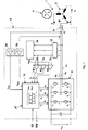
- a three-phase brushless DC motor 1 is shown very schematically with its stator 2 and a permanent magnet rotor 4.
- the stator 2 has three winding strands a, b and c, which are arranged here in Stem circuit, for example.
- the winding strands a, b, c are for the rotary drive of the rotor 4 by a control circuit 6 for generating a magnetic stator field in response to the rotor position (rotational position) with winding currents i a , i b , i c driven.
- the control circuit 6 has a bridge circuit 8 with electronic switching elements T1 to T6 as well as a control unit 10 that controls them.
- the control unit 10 may advantageously be formed by a microcontroller .mu.C.
- the bridge circuit 8 is a full bridge of six electronic switching elements T1 to T6.
- the bridge circuit 8 is fed on the input side via a DC voltage intermediate circuit U DC and is connected on the output side via three winding connection lines A, B, C to the three winding phases a, b, and c of the motor 1.
- the switching elements T1 to T6 are controlled by the control unit 10 via control signals G 1 to G 6 . In that regard, this is known per se.
- a filter 12 is connected to the sensorless rotor position detection, which is to suppress the PWM-related switching frequency.
- the voltages filtered here are, on the one hand, fed directly to a comparator K1, K2, K3 and, on the other hand, to a device 14 for motor star point simulation, which generates a reference voltage u ref , which is likewise fed to the comparators K1, K2, K3.
- the filtered output voltages u ' a , u' b and u ' c are compared with the reference voltage u ref by the comparators K1 to K3, thereby providing digital output signals P a , P b , P c , which are the polarity of the induced in the motor winding strands Specify voltages. These signals are supplied to the control unit 10.
- the control unit 10 may have a control signal input SS and a feedback output RM.
- a current controller is integrated, which may be stored, for example as a digital algorithm. This current controller compares the current actual values with internally stored, according to the invention predetermined current setpoint curves i aSoll , i bSoll .
- the voltage at the terminals of the motor winding phases a, b, c can be advantageously changed by suitable control of the switching elements of the bridge circuit 8 via a suitable pulse width modulation (PWM) such that desired and actual values are as possible good match.
- PWM pulse width modulation
- the rotor position detection takes place in a manner known per se sensorless by evaluation of the induced in the motor winding strands a, b, c due to the rotating permanent magnet rotor 4 voltages (signals P a , P b , P c ).
- flow control make sure that the currents are given in such a way that time phases alternate, in which either all three or only two winding strands energized become. It is basically irrelevant whether the engine 1 in star (like shown) or is connected in delta. For simplicity, refer the following explanations to the star circuit shown in Fig. 1, however The method according to the invention can also be used analogously for motors in delta connection be applied.
- the rotor position is determined from the detection of the Polradbeginn. For this purpose, the voltage in the currently not energized motor line is evaluated. In the simplest case, only the polarity of this voltage or its zero crossings is detected. This results in six pulses per electrical revolution. Since in many applications with a relatively large moment of inertia, as often in fan applications, the speed can only change relatively slowly, it can be assumed that the rotor position ⁇ between two pulses with interpolation can be determined accurately enough.
- the control unit 10 If the rotor position-dependent values of the pole wheel voltage u pa ( ⁇ ), ⁇ pb ( ⁇ ) and ⁇ pc ( ⁇ ) are stored in the controller and the motor currents i a (t), i b (t) and i c (t) are measured the control unit 10 "online” at any time the current torque m or calculate the required for a specific torque currents. However, the same calculations can also be carried out "offline", ie, the current waveforms required for a desired torque curve are calculated in advance and z. B. stored in the form of a table in the control unit.
- the motor currents are predetermined so that the calculated torque m remains uniform, preferably constant.
- Essential to the present invention is now the realization that instead of the third degree of freedom is used to control the rate of change of current during commutation. As a result, although the deteriorated Efficiency, the acoustic noise but are significantly lower, the otherwise disturbing commutation noises disappear.
- i a (t) i a (t 1 ) ⁇ (T 2 -t) / (t 2 - t 1 ) if t 1 ⁇ t ⁇ t 2 .
- t 1 is the time when the time phase starts with three energized motor lines
- t 2 is the time when the next time phase begins with two lines energized.
- Fig. 5 the current waveforms according to the cosine function can be seen.
- the Current gaps in the current flow in each case in the range of the zero crossing of Pole-wheel voltage enables cost-effective and robust sensorless detection the rotor position. Due to the power gaps but not the maximum possible Range can be used for torque generation. For the same Motor torque, a larger effective winding current is required.
- the Gaps therefore increase the copper losses in the engine compared to the operation without Electricity gaps. With increasing width (time length) worsens the Motor efficiency.
- this disadvantage is eliminated by that the width or time length of the power gaps depending on instantaneous operating state of the engine is changed. At relatively large Acceleration is inserted a larger current gap to despite interpolation error to ensure reliable detection of the zero crossings. In this case, a Reduction of the efficiency with regard to a better dynamic behavior the engine accepted. In stationary operation, d. H. with uniform or constant speed, the current gap, on the other hand, to a small, for the Lüer charged just enough width reduced, reducing the efficiency is optimized. Again, to achieve a quiet engine operation of the Current history predetermined so that it leads to a uniform motor torque and at the same time has no rapid changes in current.
- the current shape can for the desired current gap width, for example on the following relationships are calculated.
- the current slope and the change in the current gradient are preferably limited. It is therefore the first and second derivative of the current after the time or after the rotation angle.
- the limit ⁇ and for the change of the limit A is specified.
- the specified equation systems for the current ranges with and without current gap can be used to determine the desired current curves according to conventional numerical methods be solved offline or online.
- the gradients are called Function of the angle of rotation and the width of the current gap in the scheme or in the Control unit 10 deposited.
- the solution is during the Execution of the control continuously recalculated.
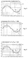
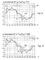
- FIGS. 6 to 10 illustrate by way of example the current profiles thus calculated for different wide power gaps taking into account the optimum Course without current gap (Fig. 6) related copper losses of the engine.
- the Current gap is preferably increased when the engine accelerates, d. H. if the zero crossing of the Polradschreib at an earlier time with respect to interpolated angle occurs.
- the current controller is a current setpoint curve, for example, as shown in FIG. 9 or 10, with a wider current gap before Zero crossing of the Polradschreib supplied. This happens z. B. at an increase of the torque setpoint (current setpoint amplitude), which remains constant Lastmoment leads to an acceleration of the engine.
- the current gap is then reduced when the angular acceleration of the motor is small, or if it operates at a steady speed (stationary).
- the Current regulator is this a current setpoint curve, for example, as shown in FIG. 7 or 8 with a relatively smaller current gap before the zero crossing of the Polradbeginning.
- the angular acceleration can be over the temporal change of Engine speed, which is already known for the angular interpolation, are determined.
- Another advantageous possibility is the comparison of the interpolated rotation angle with the real angle of rotation of the motor at the time of zero crossing the
- the inventive method described allows a low noise Motor operation with high efficiency and at the same time a cost-effective sensorless rotor position detection via the acquisition and evaluation the pole wheel voltage of the motor.
- a comparable engine efficiency can be achieved, as in an operation with Rotor position sensors. This is particularly advantageous in applications where the Engine speed is not changed frequently, as for example with fans and Pumps is the case.
- the invention is not limited to the illustrated and described embodiments (three-phase motor, star connection, magnetization shape, etc.) limited, but also includes all the same in the sense of the inventions embodiments. So can the motor also have a different number of strings and / or in delta connection be switched. It should be mentioned again that the invention is not limited to the Use of a current controller is limited, but the desired current shape can also be achieved without current measurement by suitable modulation of the voltage become.
- the invention is not limited to those in the independent claims each containing feature combination limited, but can also by any other combination of individual features of all disclosed Be defined characteristics. In this respect, the claims are only the first To understand formulation attempt for an invention.
Abstract
Description
Die vorliegende Erfindung betrifft ein Verfahren zur Kommutierung eines bürstenlosen
Gleichstrommotors gemäß dem Oberbegriff des Anspruchs 1 sowie ein
entsprechendes Steuersystem nach dem Oberbegriff des Anspruchs 16. Ferner betrifft
die Erfindung auch einen bürstenlosen Gleichstrommotor, der zur Kommutierung nach
dem erfindungsgemäßen Verfahren mit einem solchen Steuersystem ausgestattet ist.The present invention relates to a method for commutating a brushless
DC motor according to the preamble of
Permanenterregte, elektronisch kommutierte Gleichstrommotoren (sog. EC-Motoren; EC= electronically commutated) werden heute für viele Anwendungen eingesetzt, weil sie im Vergleich zu Motoren, die mechanische Kommutatoren (Bürsten) aufweisen, durch Vermeidung von Verschleißteilen (Kommutator, Bürsten, Schleifringe) auch ohne besondere Wartungsmaßnahmen eine hohe Lebenserwartung haben. Zudem zeichnen sich solche permanenterregte Motoren durch einen guten Wirkungsgrad und hohe Energiedichte aus. Ein wichtiger Anwendungsbereich solcher EC-Motoren sind Ventilatoren, bei denen ein geräuscharmer Betrieb eine immer größere Rolle spielt. Diesbezüglich sind bekannte Motor-Ausführungen und Kommutierungverfahren noch verbesserungsbedürftig.Permanently excited, electronically commutated DC motors (so-called EC motors; EC = electronically commutated) are used today for many applications because compared to motors which have mechanical commutators (brushes), by avoiding wear parts (commutator, brushes, slip rings) even without special maintenance measures have a high life expectancy. moreover Such permanent-magnet motors are characterized by good efficiency and efficiency high energy density. An important area of application of such EC motors are Fans in which quiet operation is playing an increasingly important role. In this regard, known motor designs and commutation are still in need of improvement.
Es sind EC-Motoren mit unterschiedlichen Wicklungsausführungen bekannt. Weit verbreitet sind ein-,zwei- und dreisträngige Motoren. Sowohl ein- als auch zweisträngige Ausführungen erzeugen statt einem Drehfeld nur ein pulsierendes Magnetfeld, weshalb der Motor eine große Drehmomentwelligkeit aufweist. Kritisch ist hierbei der Anlauf solcher Motoren, weil es Rotorpositionen gibt, in denen kein genügendes Anlaufmoment erzeugt werden kann. Um den sicheren Anlauf trotzdem zu gewährleisten, besitzen solche Motoren ein speziell ausgebildetes Statorblechpaket, welches mit dem Rotor einen ungleichförmigen Luftspalt bildet. Dadurch entsteht ein Reluktanzmoment, das dafür sorgt, dass der Rotor nach Abschalten der Stromversorgung nicht in den für den Anlauf kritischen Positionen stehenbleibt. Das pulsierende Feld und das erhöhte Reluktanzmoment (Rast- oder Ruckmoment) erzeugen jedoch höhere Schwingungen im Rotor. Deshalb kommt für geräuschsensitive Anwendungen in aller Regel ein dreisträngiger EC-Motor mehr in Betracht als die ein- oder zweisträngigen Varianten.There are known EC motors with different winding designs. Far One, two and three-strand engines are widespread. Both on and off Double-stranded versions produce only a pulsating one instead of a rotating field Magnetic field, which is why the motor has a large torque ripple. Is critical Here the start of such engines, because there are rotor positions in which no sufficient starting torque can be generated. In order to safely start nevertheless To ensure such engines have a specially trained Stator laminated core, which forms a non-uniform air gap with the rotor. This creates a reluctance torque that causes the rotor to decay Do not switch off the power supply to the critical positions for startup stop. The pulsating field and the increased reluctance torque (latching or Jerk moment), however, generate higher vibrations in the rotor. That's why it comes for noise-sensitive applications usually a three-phase EC motor more in Consider as the single- or double-stranded variants.
Dabei hat ein solcher EC-Motor typischerweise eine ungefähr trapezförmige Luftspaltinduktion. Die Kommutierungselektronik eines dreistängigen Motors besteht aus einer Halbleiterbrücke mit sechs elektronischen Schaltelementen (Transistoren). Bei einer üblichen Blockkommutierung werden diese jeweils paarweise so eingeschaltet, dass ein magnetisches Stator-Drehfeld erzeugt wird. Damit ergeben sich sechs mögliche Schaltzustände, die sich periodisch abwechseln. Die Drehzahl des Motors kann durch die effektive Motorspannung gesteuert werden. Dazu wird entweder die Versorgungspannung, die sogenannte Zwischenkreisspannung, verändert, oder es wird einer der jeweils zwei leitenden Transistoren pulsweitenmoduliert getaktet (PWM).In this case, such an EC motor typically has an approximately trapezoidal Air gap induction. The commutation electronics of a three-speed motor consists from a semiconductor bridge with six electronic switching elements (transistors). In a conventional block commutation these are pairwise so switched on that a magnetic stator rotating field is generated. This results six possible switching states, which alternate periodically. The speed of the Motors can be controlled by the effective motor voltage. This will either the supply voltage, the so-called DC link voltage, changed, or it is one of the two conductive transistors pulse-width modulated clocked (PWM).
Bei einem EC-Motor wird die Kommutierungselektronik in Abhängigkeit von der Rotorlage (Rotor-Drehstellung) gesteuert. Dazu muß folglich die jeweils aktuelle Rotorlage erfaßt werden. Vielfach werden dazu gesonderte Sensorelemente eingesetzt, wie beispielsweise Hall-Sensoren, die das magnetische Feld des Rotors erfassen. Bei einem dreisträngigen Motor werden meistens drei Sensorelemente verwendet (insbesondere digitale Hall-ICs). Findet an der Stelle eines Sensorelementes durch den sich drehenden Rotor ein magnetischer Polwechsel statt, ändert sich der Pegel des Sensorausgangssignals. Bei jedem Pegelwechsel werden die Schaltelemente der Steuerschaltung umgeschaltet. Diese Art der Rotorlage-Erfassung ist insbesondere bei Motoren mit extemer Kommutierungselektronik nachteilig. Zum einen machen die notwendigerweise innerhalb des Motors angeordneten Sensoren den Motor temperaturempfindlich und deshalb fehleranfällig. Zum anderen bilden die notwendigen Verdrahtungen und (Steck-) Verbindungen der Sensoren Fehlerquellen. Außer der erhöhten Fehleranfälligkeit ist auch der Zusatzaufwand nachteilig: Die Sensoren, ihre mechanischen Halterungen, die Kabelverbindungen mit Steckern usw. führen zu hohen Herstellungskosten.In an EC motor, the commutation electronics depending on the Rotor position (rotor rotation position) controlled. Therefore, the respective current must Rotor position are detected. In many cases separate sensor elements used, such as Hall sensors, the magnetic field of the rotor to capture. In a three-stranded engine are usually three sensor elements used (especially digital Hall ICs). Finds in the place of one Sensor element through the rotating rotor, a magnetic pole change instead, the level of the sensor output signal changes. At each level change the switching elements of the control circuit switched. This type of rotor position detection is especially for motors with extemer commutation electronics disadvantageous. For one, they necessarily do within the engine sensors arranged the engine temperature sensitive and therefore error prone. On the other hand, the necessary wiring and (plug) connections of the Sensors sources of error. Except the increased error rate is also the Additional expense disadvantageous: the sensors, their mechanical mounts, the Cable connections with plugs etc. lead to high production costs.
Eine günstige Lösung bietet eine ebenfalls bekannte sensorlose Rotorlage-Erfassung. Hierbei bedeutet "sensorlos", dass keine Sensoren als gesonderte Bauelemente vorgesehen sind, um mechanische Größen direkt zu erfassen. Vielmehr werden für eine indirekte Erfassung der Rotorlage nur elektrisch meßbare Größen verwendet. A favorable solution offers a likewise known sensorless rotor position detection. Here, "sensorless" means that no sensors as separate components are provided to detect mechanical variables directly. Rather, for an indirect detection of the rotor position uses only electrically measurable quantities.
Dadurch entfallen nicht nur die Sensoren selbst, sondern auch ihre mechanischen Halterungen und elektrischen Anschlußleitungen. Eine kostengünstige und bei Lüfteranwendungen vielfach verwendete Ausführung wertet nur die Polarität der inneren Motorspannungen bzw. der induzierten Motorspannungen aus. Da bei einer Blockkommutierung außerhalb des eigentlichen Kommutierungsvorgangs immer nur zwei Wicklungsstränge bestromt werden, kann in einer jeweils stromlosen Motorleitung die innere Motorspannung, die vom Rotor in dem entsprechenden Wicklungsstrang induziert wird, direkt erfasst werden. Dazu werden hauptsächlich Komparatorschaltungen benötigt.This eliminates not only the sensors themselves, but also their mechanical Brackets and electrical connection cables. An inexpensive and at Fan applications often used only evaluates the polarity of the internal motor voltages or the induced motor voltages. Because at one Block commutation outside the actual commutation process only ever two winding strands can be energized, in a respective de-energized motor line the internal motor voltage coming from the rotor in the corresponding phase winding is induced to be detected directly. This will be mainly Comparator circuits needed.
Nachteile der bekannten Blockkommutierung sind eine relativ große Drehmomentwelligkeit sowie auch schnelle Stromänderungen in den Kommutierungszeitpunkten. Beides kann zu ungünstigen akustischen Geräuschen führen.Disadvantages of the known block commutation are a relatively large Torque ripple as well as rapid current changes in the Commutation. Both can lead to unfavorable acoustic noise to lead.
Die DE 100 23 370 A1 beschreibt eine sogenannte 12-Schritt-Kommutierung, bei der durch Einführung von sechs zusätzlichen Kommutierungsschritten das Geräuschverhalten verbessert werden kann.DE 100 23 370 A1 describes a so-called 12-step commutation in which by introducing six additional commutation steps the Noise behavior can be improved.
Sowohl bei der traditionellen 6-Schritt-Kommutierung als auch bei der erwähnten 12-Schritt-Kommutierung können aber Drehmomentschwankungen und die auftretenden schnellen Stromänderungen während der Kommutierung zu unerwünschten akustischen Effekten führen.Both in the traditional 6-step commutation and in the mentioned 12-step commutation but can torque fluctuations and the occurring rapid current changes during commutation to unwanted lead to acoustic effects.
Die EP 1 104 087 A2 beschreibt Maßnahmen zur Steuerung eines Gleichstrommotors,
wobei ein sinusähnlicher Spannungs-/Stromverlauf mit Lücken vorgegeben wird. Die
hierfür geeigneten Motoren müssen eine ebenfalls sinusförmige Luftspaltinduktion, d.
h. sinusförmig verlaufende induzierte Wicklungsspannungen aufweisen, und haben
dadurch den Nachteil, dass sie gegenüber sonst üblichen EC-Motoren eine geringere
Ausnutzung besitzen. Dies bedeutet, dass für das gleiche Motordrehmoment ein
größeres Bauvolumen erforderlich ist. Für EC-Motoren mit im Wesentlichen
trapezförmiger Luftspaltinduktion ist der bekannte sinusförmige Verlauf daher nicht
geeignet. Zudem führen die eingefügten Stromlücken zu einer Zunahme der
Drehmomentschwankung im Vergleich zur idealen Sinusform.
Der vorliegenden Erfindung liegt die Aufgabe zugrunde, zur Ansteuerung von bürstenlosen Gleichstrommotoren ein Verfahren und ein Steuersystem der eingangs beschriebenen, gattungsgemäßen Art zu schaffen, womit ein besonders ruhiger, geräuscharmer Betrieb mit hohem Wirkungsgrad unter Anwendung einer robusten, d. h. störungsunanfälligen und kostengünstigen Rotorlage-Erfassung ohne gesonderte Rotorlagesensoren erreicht wird.The present invention is based on the object for controlling brushless DC motors, a method and a control system of the beginning described, generic type to create what a particularly quiet, low-noise operation with high efficiency using a robust, d. H. Non-susceptible and cost-effective rotor position detection without separate Rotor position sensors is achieved.
Erfindungsgemäß ist dazu bei dem Verfahren nach Anspruch 1 bzw. bei dem für
dieses Verfahren ausgelegten Steuersystem nach Anspruch 16 vorgesehen, dass die
Wicklungsströme mit einem bestimmten, von dem Verlauf der in den
Wicklungssträngen induzierten Polradspannungen abhängigen Soll-Verlauf derart
vorgegeben werden, dass sie ein über die Rotor-Drehung hinweg vorbestimmtes
Motordrehmoment bewirken, über die Motor-Drehung hinweg kontinuierlich ohne
abrupte, schaltbedingte Sprünge verlaufen sowie Stromlücken für die sensorlose
Rotorlage-Erfassung aufweisen.According to the invention in the method according to
Erfindungsgemäß wird somit der Motor bzw. seine Wicklungsstränge mit bezüglich ihres zeitlichen Verlaufs speziell erzeugten (generierten) Wicklungsströmen angesteuert, wobei die Verlaufsform so gewählt und vorgegeben wird, dass ein bestimmtes, vorzugsweise gleichförmiges (konstantes) Drehmoment entsteht. Durch die dabei erzeugten Stromlücken ist vorteilhafterweise eine sensorlose Rotorlage-Erfassung durch Auswertung der induzierten Polradspannungen möglich, indem diese jeweils am gerade nicht angesteuerten Wicklungsstrang erfasst werden können. Zudem werden nachteilige Stromsprünge bzw. rein. induktiv bestimmte Abschaltflanken durch eine langsame bzw. verlangsamte Stromkommutierung vermieden. Dies bedeutet, dass jeweils im Übergang zu einer Stromlücke hin der Strom nicht einfach abgeschaltet, sondern erfindungsgemäß nach einer bestimmten Funktion verlangsamt bis auf Null reduziert wird. Durch diese Vermeidung von schnellen Stromänderungen werden sonst übliche Kommutierungsgeräusche nahezu eleminiert, zumindest aber deutlich reduziert.According to the invention thus the motor or its winding strands with respect to their time course specially generated (generated) winding currents controlled, the waveform is selected and specified so that a certain, preferably uniform (constant) torque arises. By the generated power gaps is advantageously a sensorless rotor position detection by evaluating the induced pole wheel voltages possible by this can be detected in each case at just not driven winding strand. In addition, adverse current jumps or pure. inductively certain cut-off edges avoided by a slow or slowed current commutation. This means that in each case in the transition to a current gap towards the stream not easy switched off, but slows down according to the invention for a particular function is reduced to zero. By avoiding fast current changes otherwise usual Kommutierungsgeräusche are almost eliminated, but at least significantly reduced.
Zur Vorgabe der Wicklungsströme kann grundsätzlich eine beliebige geeignete Methode angewandt werden. So kann mit Vorteil ein Stromregler verwendet werden, dem die gewünschte, vorher festgelegte Stromform als Sollwert vorgegeben wird, und der dann die Istwerte der Ströme entsprechend auf die Sollwerte einregelt. Alternativ kann auch - ohne Strommessung - der zum Erreichen eines vorbestimmten Stromverlaufs notwendige Spannungsverlauf vorgegeben und beispielsweise in einem Speicher abgelegt werden. Ebenso denkbar ist auch eine dynamische Berechnung ("online") des erforderlichen Spannungsverlaufs während des Betriebs, indem z.B. ein mathematisches Modell des Motors in der Steuereinheit hinterlegt ist. Entsprechend dem so vorgegebenen "Referenzspannungsverlauf" wird dann die Statorspannung des Motors insbesondere durch Pulsweitenmodulation (PWM) vorgegeben.To specify the winding currents can in principle any suitable Method be applied. So can be used with advantage a current regulator, the desired, predetermined current form is specified as a setpoint, and then adjusts the actual values of the currents according to the setpoints. alternative can also - without current measurement - to achieve a predetermined Course of current necessary voltage curve given and, for example, in one Memory are stored. Also conceivable is a dynamic calculation ("online") of the required voltage during operation, e.g. one mathematical model of the engine is stored in the control unit. Corresponding The so-called "reference voltage curve" is then the stator voltage of Motor specified in particular by pulse width modulation (PWM).
In einer vorteilhaften Weiterbildung der Erfindung wird die Breite oder zutreffender die zeitliche Länge der Stromlücken in Anpassung an den jeweiligen Betriebszustand (insbesondere Beschleunigung bzw. stationärer Betrieb mit gleichförmiger (konstanter) Drehzahl) variiert, um dadurch den Wirkungsgrad noch zu maximieren. Bei einer relativ großen Beschleunigung wird eine größere Stromlücke vorgesehen, um trotz eventueller Interpolationsfehler eine sichere Erfassung und Auswertung der Polradspannung zu gewährleisten. Hierbei wird dann eine Reduzierung des Wirkungsgrades hinsichtlich eines besseren dynamischen Verhaltens des Motors in Kauf genommen. Im stationären Betrieb mit gleichförmiger Drehzahl wird die Stromlücke dagegen auf eine kleinere, für die Rotorlage-Erfassung gerade noch ausreichende Breite bzw. Länge reduziert, so dass insgesamt ein höherer Wirkungsgrad erzielt wird.In an advantageous embodiment of the invention, the width or more appropriate the time length of the current gaps in adaptation to the respective operating state (in particular acceleration or stationary operation with uniform (constant) Speed), thereby maximizing the efficiency. At a relative Great acceleration will provide a larger power gap despite possible interpolation error, a secure acquisition and evaluation of the To ensure pole wheel voltage. Here then a reduction of Efficiency in terms of a better dynamic behavior of the engine in Purchase taken. In stationary operation at a uniform speed is the Current gap on the other hand to a smaller, for the rotor position detection just yet sufficient width or length reduced, so that a total of a higher Efficiency is achieved.
Es sei noch bemerkt, dass die Erfindung auch einen bürstenlosen Gleichstrommotor umfaßt, der unter Anwendung des erfindungsgemäßen Verfahrens mit einem Steuersystem nach der Erfindung ausgestattet ist.It should be noted that the invention also includes a brushless DC motor which comprises using the method according to the invention with a Control system is equipped according to the invention.
Weitere vorteilhafte Ausgestaltungsmerkmale der Erfindung sind in den abhängigen Ansprüchen und der folgenden Beschreibung enthalten. Anhand der Zeichnungen soll die Erfindung beispielhaft näher erläutert werden. Dabei zeigen:
- Fig. 1
- ein Schaltbild eines erfindungsgemäßen Steuersystems in einer bevorzugten Ausführungsform zur Kommutierung eines dreisträngigen Motors,
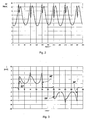
- Fig. 2 und 3
- Diagramme zur Erläuterung des Standes der Technik, und zwar Fig. 2 das berechnete Drehmoment und Fig. 3 den Wicklungsstrom in einer Phase (einem Wicklungsstrang) eines herkömmlich blockkommutierten dreisträngigen EC-Motors,
- Fig. 4
- ein Diagramm mit beispielhaften erfindungsgemäßen Stromformen mit Stromlücken, langsamer - hier linearer - Kommutierung und konstantem Drehmoment,
- Fig. 5
- ein weiteres Diagramm mit erfindungsgemäßen Stromformen wie in Fig. 4, hier jedoch mit sanfter Kommutierung gemäß einer "S-Kurve",
- Fig. 6
bis 10 - einige beispielhafte Stromform-Diagramme (nur für einen Wicklungsstrang a eines dreisträngigen EC-Motors) für ein konstantes Drehmoment m mit langsamer Stromkommutierung für unterschiedlich breite Stromlücken mit den dadurch entstehenden verschiedenen relativen Kupferverlusten PCu/PCu0 des Motors.
- Fig. 1
- a circuit diagram of a control system according to the invention in a preferred embodiment for commutation of a three-phase motor,
- FIGS. 2 and 3
- FIG. 2 shows the calculated torque, and FIG. 3 shows the winding current in one phase (one winding phase) of a conventional block-commutated three-phase EC motor.
- Fig. 4
- a diagram with exemplary current forms according to the invention with current gaps, slower - in this case linear - commutation and constant torque,
- Fig. 5
- another diagram with current forms according to the invention as in Fig. 4, but here with gentle commutation according to an "S-curve",
- Fig. 6 to 10
- some exemplary current waveform diagrams (only for a winding strand a of a three-phase EC motor) for a constant torque m with slow current commutation for different widths gaps with the resulting different relative copper losses P Cu / P Cu0 of the engine.
In Fig. 1 ist beispielhaft ein dreisträngiger kollektorloser Gleichstrommotor 1 stark
schematisch mit seinem Stator 2 und einem permanentmagnetischen Rotor 4
dargestellt. Der Stator 2 weist drei Wicklungsstränge a, b und c auf, die hier
beispielsweise in Stemschaltung angeordnet sind. Die Wicklungsstränge a, b, c
werden zum Drehantrieb des Rotors 4 von einer Steuerschaltung 6 zur Erzeugung
eines magnetischen Statorfeldes in Abhängigkeit von der Rotorlage (Drehstellung) mit
Wicklungsströmen ia, ib, ic angesteuert. Dazu weist die Steuerschaltung 6 eine
Brückenschaltung 8 mit elektronischen Schaltelementen T1 bis T6 sowie eine diese
ansteuemde Steuereinheit 10 auf. Als Schaltelemente werden bevorzugt geeignete
Leistungshalbleiter (Transistoren) verwendet, und die Steuereinheit 10 kann mit Vorteil
von einem Mikrocontroller µC gebildet sein. Bei der dargestellten Ausführung für einen
dreisträngigen Motor besteht die Brückenschaltung 8 als Vollbrücke aus sechs
elektronischen Schaltelementen T1 bis T6. Die Brückenschaltung 8 wird eingangsseitig
über einen Gleichspannungszwischenkreis UDC gespeist und ist ausgangsseitig über
drei Wicklungsanschlussleitungen A, B, C mit den drei Wicklungssträngen a, b, und c
des Motors 1 verbunden. Die Schaltelemente T1 bis T6 werden von der Steuereinheit
10 über Steuersignale G1 bis G6 angesteuert. Insoweit ist dies an sich bekannt.In FIG. 1, by way of example, a three-phase
Mit den Ausgängen der Brückenschaltung 8, die die Wicklungsspannungen des Motors
führen, ist zur sensorlosen Rotorlage-Erfassung ein Filter 12 verbunden, welches die
PWM- bedingte Schaltfrequenz unterdrücken soll. Die hier gefilterten Spannungen
werden einerseits direkt jeweils einem Komparator K1, K2, K3 zugeführt und
andererseits einer Einrichtung 14 zur Motor-Sternpunktnachbildung, die eine
Referenzspannung uref erzeugt, die ebenfalls den Komparatoren K1, K2, K3 jeweils
zugeführt wird. Die gefilterten Ausgangsspannungen u'a, u'b und u'c werden mit der
Referenzspannung uref durch die Komparatoren K1 bis K3 verglichen, die hierdurch
digitale Ausgangssignale Pa, Pb, Pc liefern, die die Polarität der in den
Motorwicklungssträngen induzierten Spannungen angeben. Diese Signale werden der
Steuereinheit 10 zugeführt. Die Steuereinheit 10 kann einen Stellsignal-Eingang SS
und einen Rückmeldungs-Ausgang RM aufweisen.With the outputs of the
Femer ist bei der dargestellten, bevorzugten Ausführung eine Stromregelung
vorgesehen. Dazu werden mindestens zwei der drei Motorströme, hier ia und ib,
gemessen und über Verstärker 16, 18 als Istwerte ia ist und ib ist der Steuereinheit 10
zugeführt. In der Steuereinheit 10 ist ein Stromregler integriert, der beispielsweise
als digitaler Algorithmus hinterlegt sein kann. Dieser Stromregler vergleicht die
Strom- Istwerte mit intern abgelegten, erfindungsgemäß vorgegebenen Strom-Sollwertverläufen
iaSoll, ibSoll. Zur Regelung der Istwerte auf die Sollwerte kann mit
Vorteil durch entsprechende Ansteuerung der Schaltelemente der Brückenschaltung
8 die Spannung an den Anschlüssen der Motor-Wicklungsstränge a, b, c über eine
geeignete Pulsweitenmodulation (PWM) so geändert werden, dass sich Soll- und IstWerte
möglichst gut entsprechen. Die Rotorlage-Erfassung erfolgt in an sich
bekannter Weise sensorlos durch Auswertung der in den Motor-Wicklungssträngen
a, b, c aufgrund des rotierenden permanentmagnetischen Rotors 4 induzierten
Spannungen (Signale Pa, Pb, Pc).Furthermore, current regulation is provided in the illustrated, preferred embodiment. For this purpose, at least two of the three motor currents, here i a and i b , are measured and supplied via
Die vorliegende Erfindung betrifft nun speziell die Art und Weise, wie die Ströme zu
verlaufen haben, um einerseits die sensorlose Rotorlage-Erfassung zu ermöglichen
und andererseits gleichzeitig auch die anderen gesetzten Ziele der Geräuscharmut
und des hohen Wirkungsgrades zu erreichen. Dies soll im Folgenden genauer
erläutert werden:
Bei der gemäß vorliegender Erfindung bevorzugt vorgesehenen Stromregelung ist
darauf zu achten, dass die Ströme so vorgegeben werden, dass sich Zeitphasen
abwechseln, bei denen entweder alle drei oder nur zwei Wicklungsstränge bestromt
werden. Dabei ist es grundsätzlich ohne Bedeutung, ob der Motor 1 in Stern (wie
dargestellt) oder aber in Dreieck geschaltet ist. Der Einfachheit halber beziehen sich
die folgenden Erläuterungen auf die in Fig. 1 dargestellte Sternschaltung, jedoch
kann das erfindungsgemäße Verfahren analog auch für Motoren in Dreieckschaltung
angewendet werden.In the present invention preferably provided flow control
make sure that the currents are given in such a way that time phases
alternate, in which either all three or only two winding strands energized
become. It is basically irrelevant whether the
In den Phasen, in denen jeweils zwei Wicklungsstränge bzw. Motorleitungen bestromt sind, fließt in diesen Leitungen je ein Strom mit gleicher Amplitude, aber unterschiedlicher Polarität. Die Regelstrecke enthält folglich nur einen Freiheitsgrad. Der Regler regelt diesen einzigen Stromwert mit der Vorgabe der Motorspannung, was durch geeignete Modulationsverfahren realisiert werden kann.In the phases in which two winding phases or motor cables are energized, flows in these lines ever a current with the same amplitude, but different polarity. The controlled system thus contains only one degree of freedom. The controller regulates this single current value with the specification of the motor voltage, which can be realized by suitable modulation methods.
In den Phasen, in denen alle drei Wicklungsstränge bzw. Motorleitungen bestromt sind, muß die Summe aller Motorströme Null ergeben, da der Sternpunkt nicht ausgeführt ist. Die Regelstrecke enthält folglich zwei Freiheitsgrade. Werden also zwei Motorströme geregelt, ergibt sich der dritte Strom automatisch. Um eine gute Regelungsqualität zu erreichen, ist es sinnvoll, auf eine Entkoppelung der Phasen zu achten, wie es auch bei stromgeregelten Drehstromantrieben üblich ist.In the phases in which all three phase windings or motor lines are energized are, the sum of all motor currents must be zero, since the neutral point is not is executed. The controlled system thus contains two degrees of freedom. So be If two motor currents are regulated, the third current results automatically. To a good one To achieve control quality, it makes sense to decouple the phases too pay attention, as is usual with current-controlled three-phase drives.
Wenn die innere Spannung des Motors, die sogenannte Polradspannung up,
bekannt ist, die z.B. durch Messung an bestehenden Motoren oder durch eine
numerische Feldberechnung ermittelt werden kann, kann aus den Motorströmen das
Drehmoment berechnet werden. Die aktuelle mechanische Abgabeleistung P2 des
Motors ergibt sich unter Vernachlässigung von Reibung und Reluktanzmoment
(Rastmoment mr) aus der Gleichung:
Die Rotorlage-Erfassung ist nicht nur für die Feststellung der
Kommutierungszeitpunkte notwendig, sondern ermöglicht auch die
Drehzahlerfassung. Ist die Drehzahl bzw. die Winkelgeschwindigkeit ω bekannt,
kann auch das Drehmoment m berechnet werden.
Unter zusätzlicher Berücksichtigung des lageabhängigen Reluktanz- bzw.
Rastmomentes mR (α) ergibt sich das Drehmoment m nach folgender Gleichung:
Die Rotorlage wird aus der Erfassung der Polradspannung bestimmt. Dazu wird die
Spannung in der jeweils gerade nicht bestromten Motorleitung ausgewertet. Im
einfachsten Fall wird dazu nur die Polarität dieser Spannung bzw. deren
Nulldurchgänge erfasst. Dadurch ergeben sich sechs Impulse pro elektrische
Umdrehung. Da bei vielen Anwendungen mit verhältnismäßig großem
Trägheitsmoment, wie oft bei Lüfteranwendungen, sich die Drehzahl nur relativ
langsam ändern kann, kann davon ausgegangen werden, dass die Rotorlage α
zwischen zwei Impulsen mit Interpolation genau genug bestimmt werden kann.
Werden in der Steuerung die rotorlageabhängigen Werte der Polradspannung upa (α),
upb (α) und upc (α) gespeichert und die Motorströme ia (t), ib (t) und ic (t) gemessen,
kann die Steuereinheit 10 "online" in jedem Zeitpunkt das aktuelle Drehmoment m bzw.
die für ein bestimmtes Drehmoment erforderlichen Ströme berechnen. Die gleichen
Berechnungen können aber auch "offline" durchgeführt werden, d. h. die für einen
gewünschten Drehmomentverlauf erforderlichen Stromverläufe werden im Voraus
berechnet und z. B. in Form einer Tabelle in der Steuereinheit abgelegt.The rotor position is determined from the detection of the Polradspannung. For this purpose, the voltage in the currently not energized motor line is evaluated. In the simplest case, only the polarity of this voltage or its zero crossings is detected. This results in six pulses per electrical revolution. Since in many applications with a relatively large moment of inertia, as often in fan applications, the speed can only change relatively slowly, it can be assumed that the rotor position α between two pulses with interpolation can be determined accurately enough. If the rotor position-dependent values of the pole wheel voltage u pa (α), μ pb (α) and μ pc (α) are stored in the controller and the motor currents i a (t), i b (t) and i c (t) are measured the
Erfindungsgemäß werden die Motorströme so vorgegeben, dass das berechnete
Drehmoment m gleichförmig, vorzugsweise konstant bleibt. In den Phasen, in denen
jeweils nur zwei Leitungen (z. B. a und b) Strom führen, gelten die folgenden
Gleichungen
Aus diesen Gleichungen sind die gewünschten Motorströme - "offline" oder in der Regelung "online" - zu berechnen. Dabei kann in einigen Fällen das Reluktanzmoment vernachlässigt werden, wodurch sich die Berechnungen wesentlich vereinfachen lassen. From these equations are the desired motor currents - "offline" or in the Regulation "online" - to calculate. In some cases, the reluctance torque neglected, making the calculations much easier to let.
In den Zeitphasen, in denen alle drei Motorleitungen bestromt sind, geltend die
folgenden Gleichungen:
In diesem Fall haben die drei Motorströme nur zwei Gleichungen zu erfüllen. Deshalb
ist eine zusätzliche Bedingung möglich, wonach üblicherweise die Verlustleistung,
genauer gesagt der Kupferverlust Pcu, minimiert werden soll (nach der Beziehung
P=l2 · R, wobei R der Wicklungswiderstand ist):
Wesentlich für die vorliegende Erfindung ist nun die Erkenntnis, dass statt dessen der dritte Freiheitsgrad dazu benutzt wird, um die Stromänderungsgeschwindigkeit während der Kommutierung zu reduzieren. Dadurch verschlechtert sich zwar der Wirkungsgrad, die akustischen Geräusche werden aber deutlich geringer, die sonst störenden Kommutierungsgeräusche verschwinden.Essential to the present invention is now the realization that instead of the third degree of freedom is used to control the rate of change of current during commutation. As a result, although the deteriorated Efficiency, the acoustic noise but are significantly lower, the otherwise disturbing commutation noises disappear.
Im einfachsten Fall - siehe hierzu Fig. 4 - wird dazu der abzuschaltende Strom, d. h.
der Strom in derjenigen Motorleitung, die in der nächsten Zeitphase stromlos bleiben
soll, linear heruntergefahren:
Alternativ dazu kann die Stromform zur Vermeidung der schnellen Änderungen di/dt
gemäß Fig. 3 anstatt mit einem linearen Ablauf auch mit einer anderen Zeitfunktion
vorgegeben werden. Gemäß Fig. 5 kann es sich um eine etwa S-förmig verlaufende
Kurve z. B. gemäß einer Kosinus-Funktion handeln:
Bei einer "online-Realisierung" kann eine solche oder ähnliche Kurve (z. B. ein geeignetes Polynom) fortlaufend berechnet werden. Bei einer "offline-Realisierung" könnte der Verlauf dagegen z.B. normiert, in Form einer Tabelle, in der Steuereinheit abgelegt werden.In an "online realization", such a or similar curve (eg suitable polynomial) can be calculated continuously. In an "offline realization" however, the course could be e.g. normalized, in the form of a table, in the control unit be filed.
In Fig. 5 sind die Stromverläufe gemäß der Kosinus-Funktion erkennbar. Die Stromlücken im Stromverlauf jeweils im Bereich des Nulldurchgangs der Polradspannung ermöglichen eine kostengünstige und robuste sensorlose Erfassung der Rotorlage. Aufgrund der Stromlücken kann aber nicht der maximal mögliche Bereich zur Drehmomenterzeugung genutzt werden. Für das gleiche Motordrehmoment ist ein größerer effektiver Wicklungsstrom erforderlich. Durch die Lücken steigen deshalb die Kupferverluste im Motor gegenüber dem Betrieb ohne Stromlücken an. Mit zunehmender Breite (zeitlicher Länge) verschlechtert sich der Motorwirkungsgrad.In Fig. 5, the current waveforms according to the cosine function can be seen. The Current gaps in the current flow in each case in the range of the zero crossing of Pole-wheel voltage enables cost-effective and robust sensorless detection the rotor position. Due to the power gaps but not the maximum possible Range can be used for torque generation. For the same Motor torque, a larger effective winding current is required. By the Gaps therefore increase the copper losses in the engine compared to the operation without Electricity gaps. With increasing width (time length) worsens the Motor efficiency.
Durch die beschriebene Erfassung der Rotorlage über die Detektion der Nulldurchgänge der Polradspannung werden pro elektrischer Umdrehung des Motors in Abständen von je 60° el sechs Informationen über die augenblickliche Rotorlage erfasst. Zwischen den Nulldurchgängen muß der Drehwinkel interpoliert werden. Hierzu wird die Motordrehzahl durch Zeitmessung zwischen den Nulldurchgängen ermittelt. Beschleunigt der Motor, so ändert sich die Drehzahl allerdings zwischen zwei Nulldurchgängen. Zur Interpolation wird dann ein eigentlich zu kleiner Drehzahlwert verwendet, was dazu führt, dass die Stromlücke zu einem zu späten Zeitpunkt bezüglich des Nulldurchgangs der Polradspannung eingefügt wird. Dadurch könnte im schlimmsten Fall der Nulldurchgang auftreten, wenn der Wicklungsstrang noch nicht stromlos ist. Dies würde zu einem Verlust der Rotorlage-Information führen. Ein solcher Zustand muß vermieden werden, da sonst ein optimaler Motorbetrieb nicht mehr möglich wäre. Deshalb kann die Stromlücke nicht beliebig klein gewählt werden, wie es eigentlich zum Erreichen eines hohen Wirkungsgrades erforderlich wäre. Die Folge hiervon wäre eigentlich ein schlechterer Wirkungsgrad, als bei einem Betrieb mit Rotorlage-Sensoren. By the described detection of the rotor position on the detection of Zero crossings of the Polradspannung be per electric revolution of the engine At intervals of 60 ° el six information about the current rotor position detected. Between the zero crossings, the angle of rotation must be interpolated. For this purpose, the engine speed is measured by timing between the zero crossings determined. Speeds up the engine, but the speed changes between two Zero crossings. For interpolation then actually too small a speed value used, which causes the current gap too late is inserted with respect to the zero crossing of the Polradspannung. This could be in the worst case, the zero crossing will occur if the winding strand is not yet is de-energized. This would lead to a loss of rotor position information. Such a Condition must be avoided, otherwise no more optimal engine operation it is possible. Therefore, the current gap can not be chosen arbitrarily small, as it would actually be required to achieve a high efficiency. The episode This would actually be a worse efficiency than when operating with Rotor position sensors.
In bevorzugter Ausgestaltung der Erfindung wird dieser Nachteil dadurch beseitigt, dass die Breite bzw. zeitliche Länge der Stromlücken in Abhängigkeit vom augenblicklichen Betriebszustand des Motors verändert wird. Bei relativ großer Beschleunigung wird eine größere Stromlücke eingefügt, um trotz Interpolationsfehler eine sichere Erkennung der Nulldurchgänge zu gewährleisten. In diesem Fall wird eine Reduzierung des Wirkungsgrades hinsichtlich eines besseren dynamischen Verhaltens des Motors in Kauf genommen. Im stationären Betrieb, d. h. mit gleichförmiger bzw. konstanter Drehzahl wird die Stromlücke dagegen auf eine kleine, für die Lageerfassung gerade noch ausreichende Breite reduziert, wodurch der Wirkungsgrad optimiert wird. Auch hierbei wird zum Erreichen eines ruhigen Motorbetriebs der Stromverlauf so vorgegeben, dass er zu einem gleichförmigen Motordrehmoment führt und gleichzeitig keine schnellen Stromänderungen aufweist.In a preferred embodiment of the invention, this disadvantage is eliminated by that the width or time length of the power gaps depending on instantaneous operating state of the engine is changed. At relatively large Acceleration is inserted a larger current gap to despite interpolation error to ensure reliable detection of the zero crossings. In this case, a Reduction of the efficiency with regard to a better dynamic behavior the engine accepted. In stationary operation, d. H. with uniform or constant speed, the current gap, on the other hand, to a small, for the Lageerfassung just enough width reduced, reducing the efficiency is optimized. Again, to achieve a quiet engine operation of the Current history predetermined so that it leads to a uniform motor torque and at the same time has no rapid changes in current.
Die Stromform kann für die gewünschte Stromlücken-Breite beispielsweise über die folgenden Beziehungen berechnet werden.The current shape can for the desired current gap width, for example on the following relationships are calculated.
In Bereichen mit Stromlücke kann der Strom aus folgenden Gleichungen ermittelt
werden:
In Bereichen, in denen alle Motor-Wicklungsstränge stromführend sind, kann die
Berechnung der Sollströme über
Die angegebenen Gleichungssysteme für die Strombereiche mit und ohne Stromlücke
können zur Ermittlung der Soll-Stromverläufe nach üblichen numerischen Verfahren
offline oder online gelöst werden. Beim Offline-Verfahren werden die Verläufe als
Funktion vom Drehwinkel und der Breite der Stromlücke in der Regelung bzw. in der
Steuereinheit 10 hinterlegt. Beim Online-Verfahren wird die Lösung während der
Ausführung der Regelung fortlaufend neu berechnet.The specified equation systems for the current ranges with and without current gap
can be used to determine the desired current curves according to conventional numerical methods
be solved offline or online. In the offline method, the gradients are called
Function of the angle of rotation and the width of the current gap in the scheme or in the
Die Figuren 6 bis 10 veranschaulichen beispielhaft die so berechneten Stromverläufe für verschieden breite Stromlücken unter Berücksichtigung der auf den optimalen Verlauf ohne Stromlücke ( Fig. 6) bezogenen Kupferverluste des Motors. Vereinfachend wurde hierbei das Reluktanzmoment des Motors vernachlässigt. Die Stromlücke wird bevorzugt dann vergrößert, wenn der Motor beschleunigt, d. h. wenn der Nulldurchgang der Polradspannung zu einem früheren Zeitpunkt bezüglich des interpolierten Winkels auftritt. Dem Stromregler wird hierzu ein Strom-Sollwertverlauf, beispielsweise gemäß Fig. 9 oder 10, mit einer breiteren Stromlücke vor dem Nulldurchgang der Polradspannung zugeführt. Dies geschieht z. B. bei einem Anstieg des Drehmoment-Sollwertes (Stromsollwertamplitude), der bei gleichbleibendem Lastmoment zu einer Beschleunigung des Motors führt. Ist ein Drehzahlregler überlagert, so wird die Stromlücke bei einem ansteigenden Drehzahlsollwert vergrößert. Die Stromlücke wird aber auch dann vergrößert, wenn der Nulldurchgang der Polradspannung nicht innerhalb eines vordefinierten, auf den interpolierten Drehwinkel bezogenen Bereichs auftritt. Dies kann der Fall sein, wenn es bei gleichem Drehmomentsollwert zu einer Beschleunigung des Motors in Folge eines abnehmenden Lastmomentes kommen sollte.FIGS. 6 to 10 illustrate by way of example the current profiles thus calculated for different wide power gaps taking into account the optimum Course without current gap (Fig. 6) related copper losses of the engine. For simplicity, the reluctance torque of the motor was neglected. The Current gap is preferably increased when the engine accelerates, d. H. if the zero crossing of the Polradspannung at an earlier time with respect to interpolated angle occurs. The current controller is a current setpoint curve, for example, as shown in FIG. 9 or 10, with a wider current gap before Zero crossing of the Polradspannung supplied. This happens z. B. at an increase of the torque setpoint (current setpoint amplitude), which remains constant Lastmoment leads to an acceleration of the engine. Is a speed controller superimposed, so the current gap at an increasing speed setpoint increased. The current gap is also increased when the zero crossing the Polradspannung not within a predefined, on the interpolated Rotation angle related area occurs. This may be the case if it is the same Torque setpoint to an acceleration of the motor as a result of decreasing load moment should come.
Zweckmäßig wird die Stromlücke dann verkleinert, wenn die Winkelbeschleunigung des Motors klein ist, oder wenn er mit gleichförmiger Drehzahl (stationär) arbeitet. Dem Stromregler wird hierzu ein Stromsollwertverlauf beispielsweise gemäß Fig. 7 oder 8 mit einer relativ kleineren Stromlücke vor dem Nulldurchgang der Polradspannung zugeführt. Die Winkelbeschleunigung kann über die zeitliche Änderung der Motordrehzahl, die für die Winkelinterpolation bereits bekannt ist, ermittelt werden. Eine weitere vorteilhafte Möglichkeit ist der Vergleich des interpolierten Drehwinkels mit dem realen Drehwinkel des Motors zum Zeitpunkt des Nulldurchgangs der Appropriately, the current gap is then reduced when the angular acceleration of the motor is small, or if it operates at a steady speed (stationary). the Current regulator is this a current setpoint curve, for example, as shown in FIG. 7 or 8 with a relatively smaller current gap before the zero crossing of the Polradspannung fed. The angular acceleration can be over the temporal change of Engine speed, which is already known for the angular interpolation, are determined. Another advantageous possibility is the comparison of the interpolated rotation angle with the real angle of rotation of the motor at the time of zero crossing the
Polradspannung. Bei einer kleinen Abweichung (kleiner Interpolationsfehler) ist die Winkelbeschleunigung klein und umgekehrt.Internal voltage. With a small deviation (small interpolation error) is the Angular acceleration small and vice versa.
Nimmt die Motordrehzahl ab, dann tritt der Nulldurchgang der Polradspannung zu einem späteren Zeitpunkt bzgl. des interpolierten Winkels auf. Die erneute Bestromung nach der Stromlücke erfolgt deshalb bevorzugt nur dann, wenn der Nulldurchgang der Polradspannung erkannt wurde, um einen Verlust der Rotorlage-Information zu vermeiden.When the engine speed decreases, the zero crossing of the pole wheel voltage occurs at a later time regarding the interpolated angle. The renewed energization After the current gap is therefore preferred only when the zero crossing of the Pole voltage was detected to a loss of rotor position information avoid.
Das beschriebene erfindungsgemäße Verfahren ermöglicht einen geräuscharmen Motorbetrieb mit gleichzeitig hohem Wirkungsgrad sowie gleichzeitig eine kostengünstige sensorlose Rotorlage-Erfassung über die Erfassung und Auswertung der Polradspannung des Motors. In einem drehzahl-stationären Betriebsfall kann ein vergleichbarer Motorwirkungsgrad erreicht werden, wie bei einem Betrieb mit Rotorlage-Sensoren. Dies ist insbesondere bei Anwendungen vorteilhaft, bei denen die Motordrehzahl nicht häufig geändert wird, wie es beispielsweise bei Ventilatoren und Pumpen der Fall ist.The inventive method described allows a low noise Motor operation with high efficiency and at the same time a cost-effective sensorless rotor position detection via the acquisition and evaluation the pole wheel voltage of the motor. In a speed-stationary operating case, a comparable engine efficiency can be achieved, as in an operation with Rotor position sensors. This is particularly advantageous in applications where the Engine speed is not changed frequently, as for example with fans and Pumps is the case.
Mit den oben beschriebenen Stromformen sind die gesetzten Ziele erreicht. Da das berechnete Drehmoment insbesondere konstant vorgegeben wird, kann ein tatsächliches Drehmoment mit nur minimalen Schwankungen erreicht werden. Die Kommutierung erfolgt äußerst sanft, was die Kommutierungsgeräusche praktisch verschwinden lässt. Weiterhin weist der Strom Stromlücken auf, die die einfache Auswertung der Polradspannung und dadurch die kostengünstige und zuverlässige sensorlose Erfassung der Rotorlage ermöglicht.With the current forms described above, the set goals are achieved. Since that Calculated torque is given in particular constant, can actual torque can be achieved with only minimal fluctuations. The Commutation is extremely gentle, making the commutation noises practical disappears. Furthermore, the current has power gaps, which is the simple Evaluation of the Polradspannung and thereby the cost-effective and reliable Sensorless detection of the rotor position allows.
Die Erfindung ist nicht auf die dargestellten und beschriebenen Ausführungsbeispiele (dreisträngiger Motor, Sternschaltung, Magnetisierungsform usw.) beschränkt, sondern umfaßt auch alle im Sinne der Erfindungen gleichwirkenden Ausführungen. So kann der Motor auch eine andere Strangzahl aufweisen und/oder in Dreieckschaltung geschaltet sein. Femer sei nochmals erwähnt, dass die Erfindung nicht auf die Verwendung eines Stromreglers beschränkt ist, sondem die gewünschte Stromform kann auch ohne Strommessung durch geeignete Modulation der Spannung erzielt werden. The invention is not limited to the illustrated and described embodiments (three-phase motor, star connection, magnetization shape, etc.) limited, but also includes all the same in the sense of the inventions embodiments. So can the motor also have a different number of strings and / or in delta connection be switched. It should be mentioned again that the invention is not limited to the Use of a current controller is limited, but the desired current shape can also be achieved without current measurement by suitable modulation of the voltage become.
Im Übrigen ist die Erfindung auch nicht auf die in den unabhängigen Ansprüchen jeweils enthaltende Merkmalskombination beschränkt, sondern kann auch durch jede beliebige andere Kombination von Einzelmerkmalen aller insgesamt offenbarten Merkmale definiert sein. Insofern sind die Ansprüche lediglich als erster Formulierungsversuch für eine Erfindung zu verstehen.Incidentally, the invention is not limited to those in the independent claims each containing feature combination limited, but can also by any any other combination of individual features of all disclosed Be defined characteristics. In this respect, the claims are only the first To understand formulation attempt for an invention.
Claims (19)
dadurch gekennzeichnet, dass die Wicklungsströme (ia, ib, ic) mit einem bestimmten, von dem Verlauf der in den Wicklungssträngen (a, b, c) induzierten Polradspannung (upa, upb, upc) abhängigen Soll-Verlauf derart vorgegeben werden, dass sie ein über die Rotor-Drehung hinweg vorbestimmtes Motor-Drehmoment (mSoll) bewirken, über die Rotor-Drehung kontinuierlich ohne abrupte, schaltbedingte Sprünge verlaufen sowie Stromlücken für die sensorlose Rotorlage-Erfassung aufweisen.Method for electronically commutating a brushless DC motor (1) with a permanent magnetic rotor (4) and a stator (2) with a plurality of electrically offset winding strands (a, b, c), the winding strands (a, b, c) generating a magnetic Statorfeldes for rotational drive of the rotor (4) depending on the rotor position with winding currents (i a , i b , i c ) are driven, and wherein the rotor position sensorless by evaluating a at each just not current carrying winding connection line (A, B, C) measurable, by the rotor (4) in the winding strands (a, b, c) induced Polradspannung (u p ) is detected,
characterized in that the winding currents (i a , i b , i c ) with a certain, depending on the course of the winding strands (a, b, c) induced Polradspannung (u pa , u pb , u pc ) desired course be predetermined such that they cause over the rotor rotation predetermined motor torque (m desired ), run continuously over the rotor rotation without abrupt, switch-related jumps and have power gaps for the sensorless rotor position detection.
dadurch gekennzeichnet, dass die Wicklungsströme (ia, ib, ic) derart vorgegeben werden, dass ein über die Rotor-Drehung hinweg gleichförmiges, weitgehend konstantes Drehmoment (mSoll) erzeugt wird.Method according to claim 1,
characterized in that the winding currents (i a , i b , i c ) are predetermined such that a uniform over the rotor rotation, largely constant torque (m desired ) is generated.
dadurch gekennzeichnet, dass die Wicklungsströme (ia, ib, ic) so vorgegeben werden, dass sich über die Rotor-Drehung hinweg einerseits Drehwinkelbereiche, in denen alle Wicklungsstränge (a, b, c) stromführend sind, und andererseits Drehwinkelbereiche, in denen mindestens einer der Wicklungsstränge (a, b, c) aufgrund einer Stromlücke stromlos ist, abwechseln.Method according to claim 1 or 2,
characterized in that the winding currents (i a , i b , i c ) are set so that on the one hand rotation angle ranges in which all winding strands (a, b, c) are energized over the rotor rotation, and on the other hand rotation angle ranges, in which at least one of the winding strands (a, b, c) is currentless due to a current gap, alternate.
dadurch gekennzeichnet, dass die Wicklungsströme (ia, ib, ic) derart vorgegeben werden, dass jeweils beim Übergang zwischen den Drehwinkelbereichen durch eine langsame, im Vergleich zu einer bloßen Umschaltung verzögerte Stromkommutierung der kontinuierliche, sprungfreie Wicklungsstrom-Verlauf erreicht wird.Method according to claim 3,
characterized in that the winding currents (i a , i b , i c ) are predetermined such that in each case at the transition between the rotation angle ranges by a slow, compared to a mere switching delayed Stromkommutierung the continuous, jump-free winding current profile is achieved.
dadurch gekennzeichnet, dass die Wicklungsströme (ia, ib, ic) jeweils im Übergang von einem stromführenden Drehwinkelbereich zu einem Drehwinkelbereich mit Stromlücke mit linearem Verlauf nach einer bestimmten Geraden-Funktion vorgegeben werden.Method according to claim 3 or 4
characterized in that the winding currents (i a , i b , i c ) are each predetermined in the transition from a current-carrying rotation angle range to a rotation angle range with a current gap with a linear course after a certain line function.
dadurch gekennzeichnet, dass die Wicklungsströme (ia, ib, ic) jeweils im Übergang von einem stromführenden Drehwinkelbereich zu einem Drehwinkelbereich mit Stromlücke mit einer bestimmten Kurvenform, insbesondere als S-Kurve z. B. nach einer Kosinus-Funktion, vorgegeben werden.Method according to claim 3 or 4,
characterized in that the winding currents (i a , i b , i c ) in each case in the transition from a current-carrying rotation angle range to a rotation angle range with current gap with a specific waveform, in particular as S-curve z. B. after a cosine function, are given.
dadurch gekennzeichnet, dass die Stromlücken bezüglich ihrer zeitlichen Länge in Abhängigkeit vom jeweiligen Betriebszustand automatisch derart geändert werden, dass eine Verlust-Minimierung in den Wicklungssträngen (a, b, c) erreicht wird.Method according to one of claims 1 to 6,
characterized in that the current gaps are automatically changed with respect to their time length depending on the respective operating state such that a loss minimization in the winding strands (a, b, c) is achieved.
dadurch gekennzeichnet, dass bei Auftreten einer bestimmten, relativ größeren Rotor-Beschleunigung die Stromlücke derart vergrößert wird, dass sie jedenfalls noch eine sichere Erfassung der Rotorlage durch Auswertung der induzierten Polradspannung ermöglicht, während bei einer relativ geringen Beschleunigung oder im stationären, drehzahlkonstanten Betrieb zur Wirkungsgrad-Steigerung die Stromlücke auf eine kurze, für die Rotorlage-Erfassung gerade noch ausreichende Länge reduziert wird.Method according to claim 7,
characterized in that at the occurrence of a certain, relatively larger rotor acceleration, the current gap is increased such that it still allows a safe detection of the rotor position by evaluating the induced Polradspannung, while at a relatively low acceleration or stationary, constant speed operation for efficiency Increase the current gap to a short, for the rotor position detection just enough length is reduced.
dadurch gekennzeichnet, dass die Wicklungsströme (ia, ib, ic) in den Übergängen bezüglich mindestens ihrer ersten und zweiten Ableitung nach der Zeit begrenzt werden. Method according to claim 7,
characterized in that the winding currents (i a , i b , i c ) in the transitions are limited in time with respect to at least their first and second derivatives.
dadurch gekennzeichnet, dass die Wicklungsströme (ia, ib, ic) in den Übergängen bezüglich mindestens ihrer ersten und zweiten Ableitung nach dem Drehwinkel (α) begrenzt werden.Method according to claim 7,
characterized in that the winding currents (i a , i b , i c ) in the transitions with respect to at least their first and second derivative according to the rotation angle (α) are limited.
dadurch gekennzeichnet, dass in jedem Drehwinkelbereich ohne Stromlücke die Wicklungsströme (ia, ib, ic) derart unter Berücksichtung ihrer Effektivwerte nach der Gleichung ia 2 (α) + ib 2 (α) + ic 2 (α) = min vorgegeben werden, dass die Wicklungsverlsute minimiert werden.Method according to one of claims 1 to 10,
characterized in that in each rotation angle range without current gap, the winding currents (i a , i b , i c ) so taking into account their RMS values according to the equation i a 2 (α) + i b 2 (α) + i c 2 (α) = be specified min that the winding losses are minimized.
dadurch gekennzeichnet, dass die Wicklungsströme (ia, ib, ic) unter Verwendung eines Stromreglers vorgegeben werden, wobei Strom-Istwerte (ia ist, ib ist) mit dem vorgegebenen Soll-Verlauf verglichen und in Abhängigkeit von diesem Vergleich die Wicklungsstränge (a, b, c) so mit einer insbesondere pulsweitenmodulierten Spannung angesteuert werden, dass die Wicklungsströme bzw. deren Istwerte zumindest annähernd dem Soll-Verlauf entsprechen.Method according to one of claims 1 to 11,
characterized in that the winding currents (i a , i b , i c ) are set using a current regulator, current actual values (i a is , i b is ) compared with the predetermined desired course and depending on this comparison the Winding strands (a, b, c) are driven so with a particular pulse width modulated voltage that the winding currents or their actual values at least approximately correspond to the desired course.
dadurch gekennzeichnet, dass die Wicklungsströme (ia, ib, ic) ohne Strom-Messung indirekt allein durch Vorgabe eines vorbestimmten, zum Erreichen des gewünschten Stromverlaufs notwendigen Spannungsverlaufes vorgegeben werden.Method according to one of claims 1 to 11,
characterized in that the winding currents (i a , i b , i c ) are set indirectly without power measurement alone by specifying a predetermined, necessary to achieve the desired current waveform voltage curve.
dadurch gekennzeichnet, dass der vorbestimmte Verlauf der Wicklungsströme oder der vorbestimmte Spannungsverlauf in einem Speicher abgelegt und/oder jeweils während des Betriebs berechnet wird.Method according to claim 12 or 13,
characterized in that the predetermined course of the winding currents or the predetermined voltage curve stored in a memory and / or each calculated during operation.
dadurch gekennzeichnet, dass der Verlauf der Wicklungsströme (ia, ib, ic) zusätzlich auch in Abhängigkeit von einem Rastmoment (mR (α)) des Motors vorgegeben wird. Method according to one of claims 1 to 14,
characterized in that the course of the winding currents (i a , i b , i c ) in addition also in dependence on a cogging torque (m R (α)) of the motor is specified.
gekennzeichnet durch eine Auslegung zur Anwendung des Verfahrens nach einem der Ansprüche 1 bis 15.Control system for the electronic commutation of a brushless DC motor (1) with a permanent-magnetic rotor (4) and a stator (2) with a plurality of electrically offset winding strands (a, b, c) for the rotary drive of the rotor (4) by a control circuit (6) for generating a magnetic stator field as a function of the rotor position with winding currents (i a , i b , i c ) are driven, wherein the control circuit (6) arranged in a bridge circuit (8) electronic switching elements (T1 to T6) and one of these driving Control unit (10),
characterized by a design for the application of the method according to one of claims 1 to 15.
dadurch gekennzeichnet, dass die Steuereinheit (10) von einem Mikrocontroller (µC) gebildet ist.Control system according to claim 16,
characterized in that the control unit (10) is formed by a microcontroller (μC).
gekennzeichnet durch Mittel zur sensorlosen Rotorlage-Erfassung durch Auswertung einer an einer jeweils gerade nicht stromführenden Wicklungsanschlussleitung (A, B, C) meßbaren, vom Rotor (4) in den Wicklungssträngen (a, b, c) induzierten Polradspannung.Control system according to claim 16 or 17,
characterized by means for sensorless rotor position detection by evaluation of a respectively not current-carrying winding connection line (A, B, C) measurable, by the rotor (4) in the winding strands (a, b, c) induced Polradspannung.
Applications Claiming Priority (2)
| Application Number | Priority Date | Filing Date | Title |
|---|---|---|---|
| DE10332381 | 2003-07-17 | ||
| DE10332381A DE10332381A1 (en) | 2003-07-17 | 2003-07-17 | Method and control system for the electronic commutation of a brushless DC motor |
Publications (3)
| Publication Number | Publication Date |
|---|---|
| EP1499008A2 true EP1499008A2 (en) | 2005-01-19 |
| EP1499008A3 EP1499008A3 (en) | 2006-01-11 |
| EP1499008B1 EP1499008B1 (en) | 2008-10-08 |
Family
ID=33461961
Family Applications (1)
| Application Number | Title | Priority Date | Filing Date |
|---|---|---|---|
| EP04011481A Not-in-force EP1499008B1 (en) | 2003-07-17 | 2004-05-14 | Method and control system for electronic commutation of a brushless DC motor |
Country Status (4)
| Country | Link |
|---|---|
| EP (1) | EP1499008B1 (en) |
| AT (1) | ATE410816T1 (en) |
| DE (2) | DE10332381A1 (en) |
| ES (1) | ES2314314T3 (en) |
Cited By (23)
| Publication number | Priority date | Publication date | Assignee | Title |
|---|---|---|---|---|
| EP2164164A1 (en) | 2008-09-10 | 2010-03-17 | ebm-papst Mulfingen GmbH & Co.KG | Method and control system for controlling a brushless electric motor |
| CN101951211A (en) * | 2010-07-23 | 2011-01-19 | 南京航空航天大学 | Brushless direct current motor electromagnetic torque observation method based on self-adapting slipform observer |
| EP2289756A1 (en) | 2009-08-26 | 2011-03-02 | ROFA Rosenheimer Förderanlagen GmbH | Electrical rail transportation system |
| CN102522929A (en) * | 2011-12-21 | 2012-06-27 | 江门市胜思特电器有限公司 | Tapped speed regulation method of low-voltage brushless direct current motor |
| CN103501140A (en) * | 2013-10-11 | 2014-01-08 | 昆山市润苏物资有限公司 | Singlechip-based permanent magnet brushless direct-current motor control system |
| CN104653768A (en) * | 2013-11-25 | 2015-05-27 | 陕西国力信息技术有限公司 | Brushless DC (direct current) motor for large-torque precise self-locking of automobile gear selecting |
| CN104660117A (en) * | 2013-11-25 | 2015-05-27 | 陕西国力信息技术有限公司 | Brushless direct-current motor for low speed and high power of automobile clutch |
| CN104653770A (en) * | 2013-11-25 | 2015-05-27 | 陕西国力信息技术有限公司 | Brushless DC (direct current) motor for large-torque precise self-locking of automobile clutch |
| CN104660116A (en) * | 2013-11-25 | 2015-05-27 | 陕西国力信息技术有限公司 | Brushless direct-current motor for low speed and high power of automobile gearshift |
| CN105610369A (en) * | 2016-03-04 | 2016-05-25 | 合肥工业大学 | Sliding-mode observer based flux linkage observation method of asynchronous motor |
| CN104158447B (en) * | 2014-08-12 | 2016-11-30 | 南京航空航天大学 | A kind of control method for brushless direct current motor |
| US9645584B2 (en) | 2014-09-17 | 2017-05-09 | Honeywell International Inc. | Gas valve with electronic health monitoring |
| US9657946B2 (en) | 2012-09-15 | 2017-05-23 | Honeywell International Inc. | Burner control system |
| US9683674B2 (en) | 2013-10-29 | 2017-06-20 | Honeywell Technologies Sarl | Regulating device |
| US9835265B2 (en) | 2011-12-15 | 2017-12-05 | Honeywell International Inc. | Valve with actuator diagnostics |
| US9841122B2 (en) | 2014-09-09 | 2017-12-12 | Honeywell International Inc. | Gas valve with electronic valve proving system |
| US9846440B2 (en) | 2011-12-15 | 2017-12-19 | Honeywell International Inc. | Valve controller configured to estimate fuel comsumption |
| US9851103B2 (en) | 2011-12-15 | 2017-12-26 | Honeywell International Inc. | Gas valve with overpressure diagnostics |
| CN106059405B (en) * | 2016-05-30 | 2018-04-27 | 西北工业大学 | Can be torque pulsation inhibited high-power pair turns brshless DC motor phase change method |
| US9995486B2 (en) | 2011-12-15 | 2018-06-12 | Honeywell International Inc. | Gas valve with high/low gas pressure detection |
| US10024439B2 (en) | 2013-12-16 | 2018-07-17 | Honeywell International Inc. | Valve over-travel mechanism |
| US10422531B2 (en) | 2012-09-15 | 2019-09-24 | Honeywell International Inc. | System and approach for controlling a combustion chamber |
| US10503181B2 (en) | 2016-01-13 | 2019-12-10 | Honeywell International Inc. | Pressure regulator |
Families Citing this family (10)
| Publication number | Priority date | Publication date | Assignee | Title |
|---|---|---|---|---|
| DE102009028582A1 (en) | 2009-08-17 | 2011-02-24 | Robert Bosch Gmbh | Electronically commutated electric motor with a rotor position prediction and an interpolation and method |
| US8839815B2 (en) | 2011-12-15 | 2014-09-23 | Honeywell International Inc. | Gas valve with electronic cycle counter |
| US9557059B2 (en) | 2011-12-15 | 2017-01-31 | Honeywell International Inc | Gas valve with communication link |
| US8905063B2 (en) | 2011-12-15 | 2014-12-09 | Honeywell International Inc. | Gas valve with fuel rate monitor |
| US9074770B2 (en) | 2011-12-15 | 2015-07-07 | Honeywell International Inc. | Gas valve with electronic valve proving system |
| US8899264B2 (en) | 2011-12-15 | 2014-12-02 | Honeywell International Inc. | Gas valve with electronic proof of closure system |
| US8947242B2 (en) | 2011-12-15 | 2015-02-03 | Honeywell International Inc. | Gas valve with valve leakage test |
| US10564062B2 (en) | 2016-10-19 | 2020-02-18 | Honeywell International Inc. | Human-machine interface for gas valve |
| US11073281B2 (en) | 2017-12-29 | 2021-07-27 | Honeywell International Inc. | Closed-loop programming and control of a combustion appliance |
| US10697815B2 (en) | 2018-06-09 | 2020-06-30 | Honeywell International Inc. | System and methods for mitigating condensation in a sensor module |
Citations (3)
| Publication number | Priority date | Publication date | Assignee | Title |
|---|---|---|---|---|
| US5569994A (en) * | 1992-11-06 | 1996-10-29 | Georgia Tech Research Corporation | Method and apparatus for sensorless control of permanent-magnet synchronous motors |
| US6369535B1 (en) * | 2001-07-31 | 2002-04-09 | General Electric Company | Method and apparatus for current shaping in electronically commutated motors |
| US6429614B1 (en) * | 1998-04-07 | 2002-08-06 | Robert Bosch Gmbh | Method and device for controlling an electronically commutated polyphase D.C. motor |
-
2003
- 2003-07-17 DE DE10332381A patent/DE10332381A1/en not_active Withdrawn
-
2004
- 2004-05-14 DE DE502004008183T patent/DE502004008183D1/en active Active
- 2004-05-14 EP EP04011481A patent/EP1499008B1/en not_active Not-in-force
- 2004-05-14 ES ES04011481T patent/ES2314314T3/en active Active
- 2004-05-14 AT AT04011481T patent/ATE410816T1/en not_active IP Right Cessation
Patent Citations (3)
| Publication number | Priority date | Publication date | Assignee | Title |
|---|---|---|---|---|
| US5569994A (en) * | 1992-11-06 | 1996-10-29 | Georgia Tech Research Corporation | Method and apparatus for sensorless control of permanent-magnet synchronous motors |
| US6429614B1 (en) * | 1998-04-07 | 2002-08-06 | Robert Bosch Gmbh | Method and device for controlling an electronically commutated polyphase D.C. motor |
| US6369535B1 (en) * | 2001-07-31 | 2002-04-09 | General Electric Company | Method and apparatus for current shaping in electronically commutated motors |
Cited By (25)
| Publication number | Priority date | Publication date | Assignee | Title |
|---|---|---|---|---|
| EP2164164A1 (en) | 2008-09-10 | 2010-03-17 | ebm-papst Mulfingen GmbH & Co.KG | Method and control system for controlling a brushless electric motor |
| EP2289756A1 (en) | 2009-08-26 | 2011-03-02 | ROFA Rosenheimer Förderanlagen GmbH | Electrical rail transportation system |
| CN101951211A (en) * | 2010-07-23 | 2011-01-19 | 南京航空航天大学 | Brushless direct current motor electromagnetic torque observation method based on self-adapting slipform observer |
| US9995486B2 (en) | 2011-12-15 | 2018-06-12 | Honeywell International Inc. | Gas valve with high/low gas pressure detection |
| US9835265B2 (en) | 2011-12-15 | 2017-12-05 | Honeywell International Inc. | Valve with actuator diagnostics |
| US9851103B2 (en) | 2011-12-15 | 2017-12-26 | Honeywell International Inc. | Gas valve with overpressure diagnostics |
| US9846440B2 (en) | 2011-12-15 | 2017-12-19 | Honeywell International Inc. | Valve controller configured to estimate fuel comsumption |
| CN102522929A (en) * | 2011-12-21 | 2012-06-27 | 江门市胜思特电器有限公司 | Tapped speed regulation method of low-voltage brushless direct current motor |
| US11421875B2 (en) | 2012-09-15 | 2022-08-23 | Honeywell International Inc. | Burner control system |
| US10422531B2 (en) | 2012-09-15 | 2019-09-24 | Honeywell International Inc. | System and approach for controlling a combustion chamber |
| US9657946B2 (en) | 2012-09-15 | 2017-05-23 | Honeywell International Inc. | Burner control system |
| CN103501140A (en) * | 2013-10-11 | 2014-01-08 | 昆山市润苏物资有限公司 | Singlechip-based permanent magnet brushless direct-current motor control system |
| US10215291B2 (en) | 2013-10-29 | 2019-02-26 | Honeywell International Inc. | Regulating device |
| US9683674B2 (en) | 2013-10-29 | 2017-06-20 | Honeywell Technologies Sarl | Regulating device |
| CN104660117A (en) * | 2013-11-25 | 2015-05-27 | 陕西国力信息技术有限公司 | Brushless direct-current motor for low speed and high power of automobile clutch |
| CN104660116A (en) * | 2013-11-25 | 2015-05-27 | 陕西国力信息技术有限公司 | Brushless direct-current motor for low speed and high power of automobile gearshift |
| CN104653770A (en) * | 2013-11-25 | 2015-05-27 | 陕西国力信息技术有限公司 | Brushless DC (direct current) motor for large-torque precise self-locking of automobile clutch |
| CN104653768A (en) * | 2013-11-25 | 2015-05-27 | 陕西国力信息技术有限公司 | Brushless DC (direct current) motor for large-torque precise self-locking of automobile gear selecting |
| US10024439B2 (en) | 2013-12-16 | 2018-07-17 | Honeywell International Inc. | Valve over-travel mechanism |
| CN104158447B (en) * | 2014-08-12 | 2016-11-30 | 南京航空航天大学 | A kind of control method for brushless direct current motor |
| US9841122B2 (en) | 2014-09-09 | 2017-12-12 | Honeywell International Inc. | Gas valve with electronic valve proving system |
| US9645584B2 (en) | 2014-09-17 | 2017-05-09 | Honeywell International Inc. | Gas valve with electronic health monitoring |
| US10503181B2 (en) | 2016-01-13 | 2019-12-10 | Honeywell International Inc. | Pressure regulator |
| CN105610369A (en) * | 2016-03-04 | 2016-05-25 | 合肥工业大学 | Sliding-mode observer based flux linkage observation method of asynchronous motor |
| CN106059405B (en) * | 2016-05-30 | 2018-04-27 | 西北工业大学 | Can be torque pulsation inhibited high-power pair turns brshless DC motor phase change method |
Also Published As
| Publication number | Publication date |
|---|---|
| EP1499008B1 (en) | 2008-10-08 |
| DE10332381A1 (en) | 2005-02-03 |
| EP1499008A3 (en) | 2006-01-11 |
| DE502004008183D1 (en) | 2008-11-20 |
| ES2314314T3 (en) | 2009-03-16 |
| ATE410816T1 (en) | 2008-10-15 |
Similar Documents
| Publication | Publication Date | Title |
|---|---|---|
| EP1499008B1 (en) | Method and control system for electronic commutation of a brushless DC motor | |
| EP1154555B1 (en) | System for electronic commutating a brushless dc motor | |
| DE69725231T2 (en) | Single phase permanent magnet motor | |
| DE4310260C1 (en) | Electronic control device for an electronically commutated direct-current motor (DC motor) | |
| DE19860446A1 (en) | Method for controlling a voltage / frequency converter-controlled multi-phase permanent magnet motor | |
| DE102008054487A1 (en) | Control system for a multiphase electric lathe | |
| EP1076408B1 (en) | Method for starting a brushless DC-motor | |
| WO2016066307A1 (en) | Actuator drive having a brushless two-phase dc motor and use of such a dc motor | |
| EP1523090A2 (en) | Method for commutation of a brushless dc motor | |
| DE4314211C2 (en) | Method for controlling the shutdown process in the strands of a reluctance motor | |
| DE102014107949A1 (en) | Method and device for detecting a zero crossing of a current through a strand of a brushless DC motor | |
| DE4425193C1 (en) | Variable speed EC direct current motor | |
| DE102016222015A1 (en) | Electric drive and method for operating an electric motor | |
| DE10332228B4 (en) | Control method for a brushless electric motor, in particular fan motor | |
| DE19934668A1 (en) | Electronically commutated motor | |
| WO2013110501A2 (en) | Method for actuating a bldc motor | |
| DE102016215175A1 (en) | Method for operating an electric machine and electric machine | |
| DE102012012762B4 (en) | Device for determining positions of a rotor in electrical machines | |
| EP1443635A1 (en) | Method for driving a firing angle | |
| DE10127670A1 (en) | Controlling brushless 3-phase electric motor, involves using block commutation and operating motor with commutation angle less than 180 degrees and greater than 120 degrees | |
| DE2452082A1 (en) | COLLECTORLESS DC MOTOR WITH SINGLE STATOR WINDING | |
| EP0190240B1 (en) | Collector-free direct current motor | |
| DE102019215854A1 (en) | Method for operating a brushless and sensorless multiphase electric motor | |
| WO2018095482A1 (en) | Method and circuit arrangement for determining the position of a rotor in an electric motor | |
| BE1029061B1 (en) | Method for driving an at least two-phase brushless motor |
Legal Events
| Date | Code | Title | Description |
|---|---|---|---|
| PUAI | Public reference made under article 153(3) epc to a published international application that has entered the european phase |
Free format text: ORIGINAL CODE: 0009012 |
|
| AK | Designated contracting states |
Kind code of ref document: A2 Designated state(s): AT BE BG CH CY CZ DE DK EE ES FI FR GB GR HU IE IT LI LU MC NL PL PT RO SE SI SK TR |
|
| AX | Request for extension of the european patent |
Extension state: AL HR LT LV MK |
|
| PUAL | Search report despatched |
Free format text: ORIGINAL CODE: 0009013 |
|
| AK | Designated contracting states |
Kind code of ref document: A3 Designated state(s): AT BE BG CH CY CZ DE DK EE ES FI FR GB GR HU IE IT LI LU MC NL PL PT RO SE SI SK TR |
|
| AX | Request for extension of the european patent |
Extension state: AL HR LT LV MK |
|
| RIC1 | Information provided on ipc code assigned before grant |
Ipc: H02P 6/14 19950101ALI20051119BHEP Ipc: H02P 6/18 19950101ALI20051119BHEP Ipc: H02P 6/10 19950101AFI20041103BHEP |
|
| 17P | Request for examination filed |
Effective date: 20060322 |
|
| AKX | Designation fees paid |
Designated state(s): AT BE BG CH CY CZ DE DK EE ES FI FR GB GR HU IE IT LI LU MC NL PL PT RO SE SI SK TR |
|
| RTI1 | Title (correction) |
Free format text: METHOD AND CONTROL SYSTEM FOR ELECTRONIC COMMUTATION OF A BRUSHLESS DC MOTOR |
|
| GRAP | Despatch of communication of intention to grant a patent |
Free format text: ORIGINAL CODE: EPIDOSNIGR1 |
|
| RIN1 | Information on inventor provided before grant (corrected) |
Inventor name: KROTSCH, JENS, DIPL.-ING. (FH) Inventor name: LELKES, ANDRAS, DR.-ING. |
|
| GRAS | Grant fee paid |
Free format text: ORIGINAL CODE: EPIDOSNIGR3 |
|
| GRAA | (expected) grant |
Free format text: ORIGINAL CODE: 0009210 |
|
| AK | Designated contracting states |
Kind code of ref document: B1 Designated state(s): AT BE BG CH CY CZ DE DK EE ES FI FR GB GR HU IE IT LI LU MC NL PL PT RO SE SI SK TR |
|
| REG | Reference to a national code |
Ref country code: GB Ref legal event code: FG4D Free format text: NOT ENGLISH |
|
| REG | Reference to a national code |
Ref country code: CH Ref legal event code: EP |
|
| REG | Reference to a national code |
Ref country code: IE Ref legal event code: FG4D Free format text: LANGUAGE OF EP DOCUMENT: GERMAN |
|
| REF | Corresponds to: |
Ref document number: 502004008183 Country of ref document: DE Date of ref document: 20081120 Kind code of ref document: P |
|
| PG25 | Lapsed in a contracting state [announced via postgrant information from national office to epo] |
Ref country code: SI Free format text: LAPSE BECAUSE OF FAILURE TO SUBMIT A TRANSLATION OF THE DESCRIPTION OR TO PAY THE FEE WITHIN THE PRESCRIBED TIME-LIMIT Effective date: 20081008 |
|
| REG | Reference to a national code |
Ref country code: ES Ref legal event code: FG2A Ref document number: 2314314 Country of ref document: ES Kind code of ref document: T3 |
|
| NLV1 | Nl: lapsed or annulled due to failure to fulfill the requirements of art. 29p and 29m of the patents act | ||
| PG25 | Lapsed in a contracting state [announced via postgrant information from national office to epo] |
Ref country code: BG Free format text: LAPSE BECAUSE OF FAILURE TO SUBMIT A TRANSLATION OF THE DESCRIPTION OR TO PAY THE FEE WITHIN THE PRESCRIBED TIME-LIMIT Effective date: 20090108 |
|
| PG25 | Lapsed in a contracting state [announced via postgrant information from national office to epo] |
Ref country code: PT Free format text: LAPSE BECAUSE OF FAILURE TO SUBMIT A TRANSLATION OF THE DESCRIPTION OR TO PAY THE FEE WITHIN THE PRESCRIBED TIME-LIMIT Effective date: 20090218 Ref country code: FI Free format text: LAPSE BECAUSE OF FAILURE TO SUBMIT A TRANSLATION OF THE DESCRIPTION OR TO PAY THE FEE WITHIN THE PRESCRIBED TIME-LIMIT Effective date: 20081008 Ref country code: PL Free format text: LAPSE BECAUSE OF FAILURE TO SUBMIT A TRANSLATION OF THE DESCRIPTION OR TO PAY THE FEE WITHIN THE PRESCRIBED TIME-LIMIT Effective date: 20081008 Ref country code: NL Free format text: LAPSE BECAUSE OF FAILURE TO SUBMIT A TRANSLATION OF THE DESCRIPTION OR TO PAY THE FEE WITHIN THE PRESCRIBED TIME-LIMIT Effective date: 20081008 |
|
| REG | Reference to a national code |
Ref country code: IE Ref legal event code: FD4D |
|
| PG25 | Lapsed in a contracting state [announced via postgrant information from national office to epo] |
Ref country code: RO Free format text: LAPSE BECAUSE OF FAILURE TO SUBMIT A TRANSLATION OF THE DESCRIPTION OR TO PAY THE FEE WITHIN THE PRESCRIBED TIME-LIMIT Effective date: 20081008 Ref country code: EE Free format text: LAPSE BECAUSE OF FAILURE TO SUBMIT A TRANSLATION OF THE DESCRIPTION OR TO PAY THE FEE WITHIN THE PRESCRIBED TIME-LIMIT Effective date: 20081008 Ref country code: IE Free format text: LAPSE BECAUSE OF FAILURE TO SUBMIT A TRANSLATION OF THE DESCRIPTION OR TO PAY THE FEE WITHIN THE PRESCRIBED TIME-LIMIT Effective date: 20081008 Ref country code: DK Free format text: LAPSE BECAUSE OF FAILURE TO SUBMIT A TRANSLATION OF THE DESCRIPTION OR TO PAY THE FEE WITHIN THE PRESCRIBED TIME-LIMIT Effective date: 20081008 |
|
| PLBE | No opposition filed within time limit |
Free format text: ORIGINAL CODE: 0009261 |
|
| STAA | Information on the status of an ep patent application or granted ep patent |
Free format text: STATUS: NO OPPOSITION FILED WITHIN TIME LIMIT |
|
| REG | Reference to a national code |
Ref country code: HU Ref legal event code: AG4A Ref document number: E005350 Country of ref document: HU |
|
| PG25 | Lapsed in a contracting state [announced via postgrant information from national office to epo] |
Ref country code: SE Free format text: LAPSE BECAUSE OF FAILURE TO SUBMIT A TRANSLATION OF THE DESCRIPTION OR TO PAY THE FEE WITHIN THE PRESCRIBED TIME-LIMIT Effective date: 20090108 |
|
| 26N | No opposition filed |
Effective date: 20090709 |
|
| PG25 | Lapsed in a contracting state [announced via postgrant information from national office to epo] |
Ref country code: SK Free format text: LAPSE BECAUSE OF FAILURE TO SUBMIT A TRANSLATION OF THE DESCRIPTION OR TO PAY THE FEE WITHIN THE PRESCRIBED TIME-LIMIT Effective date: 20081008 |
|
| BERE | Be: lapsed |
Owner name: EBM-PAPST MULFINGEN G.M.B.H. & CO.KG Effective date: 20090531 |
|
| PG25 | Lapsed in a contracting state [announced via postgrant information from national office to epo] |
Ref country code: MC Free format text: LAPSE BECAUSE OF NON-PAYMENT OF DUE FEES Effective date: 20090531 |
|
| REG | Reference to a national code |
Ref country code: CH Ref legal event code: PL |
|
| PG25 | Lapsed in a contracting state [announced via postgrant information from national office to epo] |
Ref country code: LI Free format text: LAPSE BECAUSE OF NON-PAYMENT OF DUE FEES Effective date: 20090531 Ref country code: CH Free format text: LAPSE BECAUSE OF NON-PAYMENT OF DUE FEES Effective date: 20090531 |
|
| PG25 | Lapsed in a contracting state [announced via postgrant information from national office to epo] |
Ref country code: BE Free format text: LAPSE BECAUSE OF NON-PAYMENT OF DUE FEES Effective date: 20090531 |
|
| PG25 | Lapsed in a contracting state [announced via postgrant information from national office to epo] |
Ref country code: AT Free format text: LAPSE BECAUSE OF NON-PAYMENT OF DUE FEES Effective date: 20090514 |
|
| PG25 | Lapsed in a contracting state [announced via postgrant information from national office to epo] |
Ref country code: GR Free format text: LAPSE BECAUSE OF FAILURE TO SUBMIT A TRANSLATION OF THE DESCRIPTION OR TO PAY THE FEE WITHIN THE PRESCRIBED TIME-LIMIT Effective date: 20090109 |
|
| PG25 | Lapsed in a contracting state [announced via postgrant information from national office to epo] |
Ref country code: LU Free format text: LAPSE BECAUSE OF NON-PAYMENT OF DUE FEES Effective date: 20090514 |
|
| PG25 | Lapsed in a contracting state [announced via postgrant information from national office to epo] |
Ref country code: TR Free format text: LAPSE BECAUSE OF FAILURE TO SUBMIT A TRANSLATION OF THE DESCRIPTION OR TO PAY THE FEE WITHIN THE PRESCRIBED TIME-LIMIT Effective date: 20081008 |
|
| PG25 | Lapsed in a contracting state [announced via postgrant information from national office to epo] |
Ref country code: CY Free format text: LAPSE BECAUSE OF FAILURE TO SUBMIT A TRANSLATION OF THE DESCRIPTION OR TO PAY THE FEE WITHIN THE PRESCRIBED TIME-LIMIT Effective date: 20081008 |
|
| PGFP | Annual fee paid to national office [announced via postgrant information from national office to epo] |
Ref country code: GB Payment date: 20140521 Year of fee payment: 11 |
|
| PGFP | Annual fee paid to national office [announced via postgrant information from national office to epo] |
Ref country code: DE Payment date: 20140507 Year of fee payment: 11 Ref country code: FR Payment date: 20140527 Year of fee payment: 11 Ref country code: ES Payment date: 20140528 Year of fee payment: 11 Ref country code: IT Payment date: 20140528 Year of fee payment: 11 Ref country code: CZ Payment date: 20140512 Year of fee payment: 11 |
|
| PGFP | Annual fee paid to national office [announced via postgrant information from national office to epo] |
Ref country code: HU Payment date: 20140522 Year of fee payment: 11 |
|
| REG | Reference to a national code |
Ref country code: DE Ref legal event code: R119 Ref document number: 502004008183 Country of ref document: DE |
|
| GBPC | Gb: european patent ceased through non-payment of renewal fee |
Effective date: 20150514 |
|
| PG25 | Lapsed in a contracting state [announced via postgrant information from national office to epo] |
Ref country code: IT Free format text: LAPSE BECAUSE OF NON-PAYMENT OF DUE FEES Effective date: 20150514 |
|
| REG | Reference to a national code |
Ref country code: FR Ref legal event code: ST Effective date: 20160129 |
|
| PG25 | Lapsed in a contracting state [announced via postgrant information from national office to epo] |
Ref country code: CZ Free format text: LAPSE BECAUSE OF NON-PAYMENT OF DUE FEES Effective date: 20150514 Ref country code: HU Free format text: LAPSE BECAUSE OF NON-PAYMENT OF DUE FEES Effective date: 20150515 |
|
| PG25 | Lapsed in a contracting state [announced via postgrant information from national office to epo] |
Ref country code: GB Free format text: LAPSE BECAUSE OF NON-PAYMENT OF DUE FEES Effective date: 20150514 Ref country code: DE Free format text: LAPSE BECAUSE OF NON-PAYMENT OF DUE FEES Effective date: 20151201 |
|
| PG25 | Lapsed in a contracting state [announced via postgrant information from national office to epo] |
Ref country code: FR Free format text: LAPSE BECAUSE OF NON-PAYMENT OF DUE FEES Effective date: 20150601 |
|
| REG | Reference to a national code |
Ref country code: ES Ref legal event code: FD2A Effective date: 20160928 |
|
| PG25 | Lapsed in a contracting state [announced via postgrant information from national office to epo] |
Ref country code: ES Free format text: LAPSE BECAUSE OF NON-PAYMENT OF DUE FEES Effective date: 20150515 |